

Page 1
TABLE SAW
MODEL
C 10RA2
POWER TOOLS
C
TECHNICAL DATA
AND
C 10RA2
SERVICE MANUAL
LIST No. E929 Sep. 1999
SPECIFICATIONS AND PARTS ARE SUBJECT TO CHANGE FOR IMPROVEMENT
Page 2

REMARK:
Throughout this TECHNICAL DATA AND SERVICE MANUAL, a symbol(s)
is(are) used in the place of company name(s) and model name(s) of our
competitor(s). The symbol(s) utilized here is(are) as follows:
Competitor
Symbol Utilized
Company Name
Model Name
C MAKITA
2703
Page 3

CONTENTS
[ Business Section ]
1. PRODUCT NAME
2. MARKETING OBJECTIVE
3. APPLICA TIONS
4. SELLING POINTS
4-1. Selling Point Descriptions
5. SPECIFICATIONS
5-1. Specifications
5-2. Outside View and External Dimensions
••••••••••••••••••••••••••••••••••••••••••••••••••••••••••••••••••••••••••••••••••••••••••••••••••••••••••••••••••••••
•••••••••••••••••••••••••••••••••••••••••••••••••••••••••••••••••••••••••••••••••••••••••••••••••••••••••
•••••••••••••••••••••••••••••••••••••••••••••••••••••••••••••••••••••••••••••••••••••••••••••••••••••••••••••••••••••••••
••••••••••••••••••••••••••••••••••••••••••••••••••••••••••••••••••••••••••••••••••••••••••••••••••••••••••••••••••••••
••••••••••••••••••••••••••••••••••••••••••••••••••••••••••••••••••••••••••••••••••••••••••••••••••••••
••••••••••••••••••••••••••••••••••••••••••••••••••••••••••••••••••••••••••••••••••••••••••••••••••••••••••••••••••••••
•••••••••••••••••••••••••••••••••••••••••••••••••••••••••••••••••••••••••••••••••••••••••••••••••••••••••••••••••••••••
••••••••••••••••••••••••••••••••••••••••••••••••••••••••••••••••••••••••••••••••••
6. COMPARISONS WITH SIMILAR PRODUCTS
7. PRECAUTIONS IN SALES PROMOTION
7-1. Instruction Manual
7-2. Precautions on the Name Plate
7-3. Warning Label (A)
7-4. Warning Label (B)
7-5. Package
7-6. Packing
•••••••••••••••••••••••••••••••••••••••••••••••••••••••••••••••••••••••••••••••••••••••••••••••••••••••••••••••••••••••••••••••
••••••••••••••••••••••••••••••••••••••••••••••••••••••••••••••••••••••••••••••••••••••••••••••••••••••••••••••••••••••••••••••••
7-7. Related Laws and Regulations
••••••••••••••••••••••••••••••••••••••••••••••••••••••••••••••••••••••••••••••••••••••••••••••••••••••••••••••••
•••••••••••••••••••••••••••••••••••••••••••••••••••••••••••••••••••••••••••••••••••••••••••••
•••••••••••••••••••••••••••••••••••••••••••••••••••••••••••••••••••••••••••••••••••••••••••••••••••••••••••••••••
•••••••••••••••••••••••••••••••••••••••••••••••••••••••••••••••••••••••••••••••••••••••••••••••••••••••••••••••••
•••••••••••••••••••••••••••••••••••••••••••••••••••••••••••••••••••••••••••••••••••••••••••••
••••••••••••••••••••••••••••••••••••••••••••••••••••••••••••••••••••••••••••••••••
•••••••••••••••••••••••••••••••••••••••••••••••••••••••••••••••••••••••••••
Page
1
1
1
1
2
3
3
4
5
6
6
6
6
7
8
8
8
8. PRECAUTIONS ON OPERATION
8-1. Unpacking
8-2. Assembly
8-3. Adjustment
••••••••••••••••••••••••••••••••••••••••••••••••••••••••••••••••••••••••••••••••••••••••••••••••••••••••••••••••••••••••••••
•••••••••••••••••••••••••••••••••••••••••••••••••••••••••••••••••••••••••••••••••••••••••••••••••••••••••••••••••••••••••••••
•••••••••••••••••••••••••••••••••••••••••••••••••••••••••••••••••••••••••••••••••••••••••••••••••••••••••••••••••••••••••••
8-4. Relation between Saw Blade and Spreader
8-5. Overload Protective Device
8-6. Precautions on Using the Electric Brake
8-7. Extension Cords
8-8. Cutting Work
•••••••••••••••••••••••••••••••••••••••••••••••••••••••••••••••••••••••••••••••••••••••••••••••••••••••••••••••••••
••••••••••••••••••••••••••••••••••••••••••••••••••••••••••••••••••••••••••••••••••••••••••••••••••••••••••••••••••••••••
9. MAINTENANCE AND INSPECTION
9-1. Inspecting the Saw Blade
9-2. Inspecting the Carbon Brushes
9-3. Inspecting the Mounting Screws
•••••••••••••••••••••••••••••••••••••••••••••••••••••••••••••••••••••••••••••••••••••••••••••
•••••••••••••••••••••••••••••••••••••••••••••••••••••••••••••••••••••••••••
•••••••••••••••••••••••••••••••••••••••••••••••••••••••••••••••••••••••••••••••••••••••••••••••••••
••••••••••••••••••••••••••••••••••••••••••••••••••••••••••••••••••••••••••••••••
••••••••••••••••••••••••••••••••••••••••••••••••••••••••••••••••••••••••••••••••••••••••••
••••••••••••••••••••••••••••••••••••••••••••••••••••••••••••••••••••••••••••••••••••••••••••••••••••••
••••••••••••••••••••••••••••••••••••••••••••••••••••••••••••••••••••••••••••••••••••••••••••••
••••••••••••••••••••••••••••••••••••••••••••••••••••••••••••••••••••••••••••••••••••••••••••
9-4. Inspecting the Saw Blade Guard for Proper Operation
9-5. Regular Cleaning of the Saw Blade Guard
9-6. Storage
9-7. Lubrication
9-8. Cleaning
••••••••••••••••••••••••••••••••••••••••••••••••••••••••••••••••••••••••••••••••••••••••••••••••••••••••••••••••••••••••••••••••
•••••••••••••••••••••••••••••••••••••••••••••••••••••••••••••••••••••••••••••••••••••••••••••••••••••••••••••••••••••••••••
••••••••••••••••••••••••••••••••••••••••••••••••••••••••••••••••••••••••••••••••••••••••••••••••••••••••••••••••••••••••••••••
•••••••••••••••••••••••••••••••••••••••••••••••••••••••••••••••••••••••••••••
••••••••••••••••••••••••••••••••••••••••••••••••••••••••••••
9
9
10
12
16
16
16
17
18
19
19
19
19
20
20
20
20
20
Page 4

[ Service Section ]
10. PRECAUTIONS IN DISASSEMBLY AND REASSEMBLY
10-1. Disassembly
10-2. Reassembly
10-3. Wiring
10-4. Adjustments
10-5. Product Precision
•••••••••••••••••••••••••••••••••••••••••••••••••••••••••••••••••••••••••••••••••••••••••••••••••••••••••••••••••••••••
••••••••••••••••••••••••••••••••••••••••••••••••••••••••••••••••••••••••••••••••••••••••••••••••••••••••••••••••••••••••
•••••••••••••••••••••••••••••••••••••••••••••••••••••••••••••••••••••••••••••••••••••••••••••••••••••••••••••••••••••••••••••••••
••••••••••••••••••••••••••••••••••••••••••••••••••••••••••••••••••••••••••••••••••••••••••••••••••••••••••••••••••••••••
••••••••••••••••••••••••••••••••••••••••••••••••••••••••••••••••••••••••••••••••••••••••••••••••••••••••••••••••
••••••••••••••••••••••••••••••••••••••••••••••••••••••••
21
21
28
29
30
30
11. REPAIR GUIDE
••••••••••••••••••••••••••••••••••••••••••••••••••••••••••••••••••••••••••••••••••••••••••••••••••••••••••••••••••••••••
12. STANDARD REPAIR TIME (UNIT) SCHEDULES
[ Appendix ]
Assembly Diagram for C 10RA2
••••••••••••••••••••••••••••••••••••••••••••••••••••••••••••••••••••••••••••••••••••••••••••••••••••••••
••••••••••••••••••••••••••••••••••••••••••••••••••••••••••••••••••••
31
34
35
Page 5
1. PRODUCT NAME
Hitachi Table Saw, Model C 10RA2
2. MARKETING OBJECTIVE
The Model C 10RA2 was developed to upgrade and replace the current Model C 10RA.
The key features of the Model C 10RA2 are as follows:
(1) Smooth-sliding fence mounted on rails at the front and the rear of the table
(2) One-touch fence setting, thanks to a quick lock fence system
(3) More stable guide of a workpiece with the 3-inch-heigh fence (C 10RA: 2-inch height)
The basic structure of the product is the same as that of the Model C 10RA.
3. APPLICA TIONS
Rip-sawing and cross-cutting of ordinary wood, hardwood, plywood, composite wood materials, plastics and
similar materials.
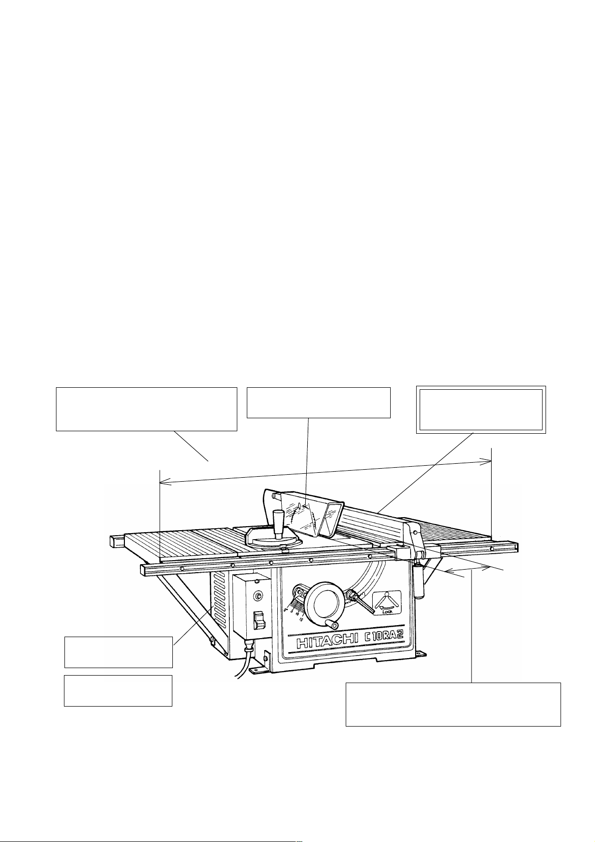
4. SELLING POINTS
Wide table
(including the extension wing, which
is standard with this model)
864 mm (34")
Equipped with 2.6 hp
high-power motor
Good work efficiency
with electric brake
High cutting capacity with
255 mm (10") chip saw
Max. ripping width of:
360 mm (14-5/32") to the right of saw blade
400 mm (15-3/4") to the left of saw blade
Smooth-sliding fence
One-touch fence setting
Fence height: 3"
--- 1 ---
Page 6
4-1. Selling Point Descriptions
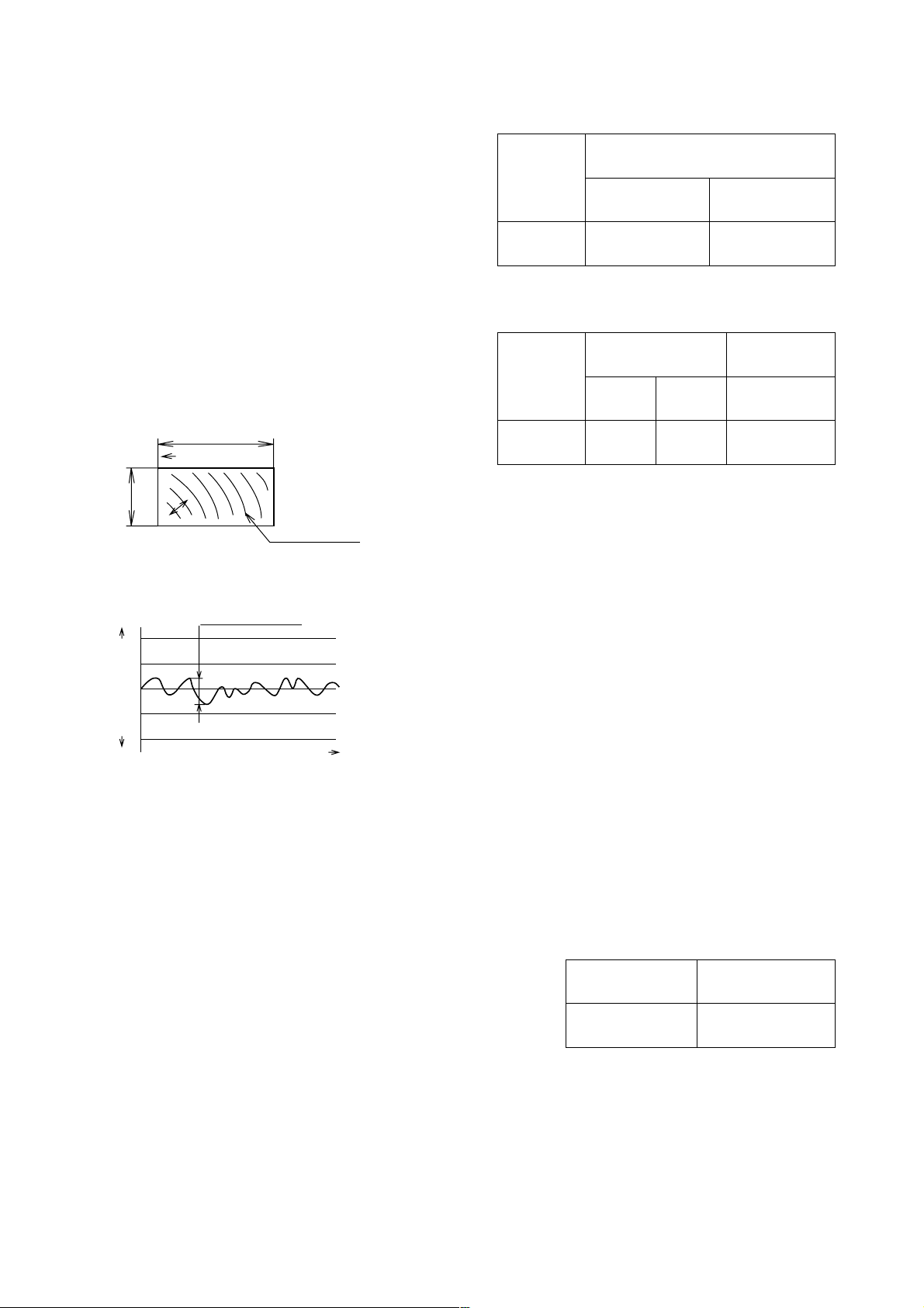
(1) Wide table
An extension wing is standard on this machine to give
the table a width of 864 mm (34"). This provides a
wide ripping surface of up to 360 mm (14-5/32") to the
right of the saw blade and up to 400 mm (15-3/4") to
the left of the saw blade when using the rip fence.
Maker/
Model name
HITACHI
C 10RA2
Table 1
(Unit: mm)
Max. ripping width
To right of saw To left of saw
blade blade
360 400
(14-5/32") (15-3/4")
(2) High cutting capacity with 255 mm (10") TCT blade
A 255 mm (10") TCT saw blade is standard on this
machine.
150 mm (5-29/32")
Cutting direction
Saw marks
60 mm (2-3/8")
Fig. 1
Surface roughness (max.)
Surface
roughness (µm)
Direction of probe
Maker/
Model name
HITACHI
C 10RA2
Table 2
Cutting depth of
saw blade
45˚
Bevel
11
---
(7/16"
2-1/2")
(0
90˚
0
---
76
---
3")
63
---
(Unit: mm)
Cut section
Max. surface
roughness
44 µm
Cutting material: Douglas fir
Percentage of water content: 13 to 16 %
Right-angle cutting in 17 seconds.
Using the roughness meter, the roughness
(irregularities in the surface shown in Fig. 2) was
measured by moving the probe in the direction of the
arrow as shown in Fig. 1.
Fig. 2
(3) Good work efficiency with electric brake
When the switch is turned off after a cutting operation, the electric brake will stop the saw blade (in about 3 --- 5
seconds). Efficient operation is assured when removing the cut material.
Table 3
(4) Equipped with a high-power 1,940 W (2.6 hp) motor
Maker/Model name
Max. output
The high-power motor facilitates fast cutting operations.
Hitachi C 10RA2 60 x 150 mm material 15 seconds
HITACHI C 10RA2
1,940 (2.6 hp)
(Unit: W)
--- 2 ---
Page 7
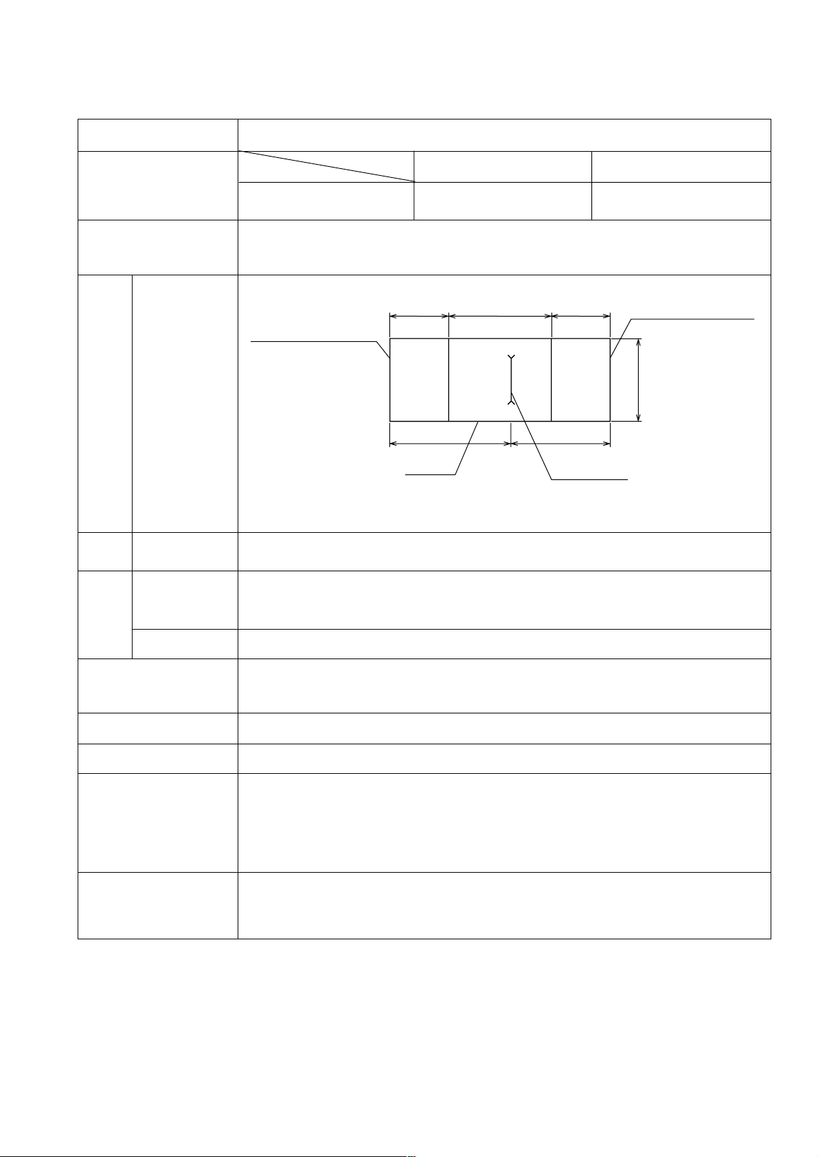
5. SPECIFICATIONS
5-1. Specifications
Item
Max. cutting depth
Saw blade dimensions
(supplied TCT blade)
Table surface
dimensions
Table
Table surface
height
Power
source
Table voltage
Specifications
Cutting angle
Saw blade
90˚ 45˚ bevel
Outer diameter 0 --- 76 mm 11 --- 63 mm
255 mm (10") (0 --- 3") (7/16" --- 2-1/2")
Outer dia. 255 mm (10") x Inner dia. 15.9 mm (5/8") x Teeth number 36
185 mm
(7-9/32")
494 mm
(19-7/16")
185 mm
(7-9/32")
Extension wing (R)
Extension wing (L)
500 mm
(19-11/16")
449 mm
(17-11/16")
Table
415 mm
(16-11/32")
Saw blade
310 mm (12-3/16")
905 mm (35-5/8") (when mounted on the optional table saw stand)
AC single phase 60 Hz, 115 V
Type
Rated current
Motor Input
No-load speed
Weight
Packaging
Cord
Standard equipment
Optional accessories
AC single phase commutator motor, 15 A, 1,640 W
5,000 /min
Net: 29 kg (64 lbs) Gross: 38 kg (84 lbs)
Net (with table saw stand): 38 kg (84 lbs) Gross: 46 kg (101 lbs)
Corrugated cardboard box
Three-core cabtire cable, 2.0 mm2 (14 A.W.G.) x 2 m (6.5 ft.)
255 mm (10") TCT saw blade (36 teeth)
Set plate
Wrench (22 mm)
Wrench (23 x 26 mm)
Elbow (chip extraction duct)
•••••••••••••••••••••••••••••••••••••••••••••••••••••••••••••••••••••••••••••••••••••••••••••••••••••••
•••••••••••••••••••••••••••••••••••••••••••••••••••••••••••••••••••••••••••••••••••••••••••
••••••••••••••••••••••••••••••••••••••••••••••••••••••••••••••••••••••••••••••••••••
•••••••••••••••••••••••••••••••••••••••••••••••••••••••••••••••••••••••••••
•••••••••••••••••••••••••••••••••••••••••••••••••••••••••
Dado insert (for dado cutter) (Code No. 314325)
Push stick (Code No. 314324)
Table saw stand (Code No. 314819)
1
4
1
1
1
--- 3 ---
Page 8
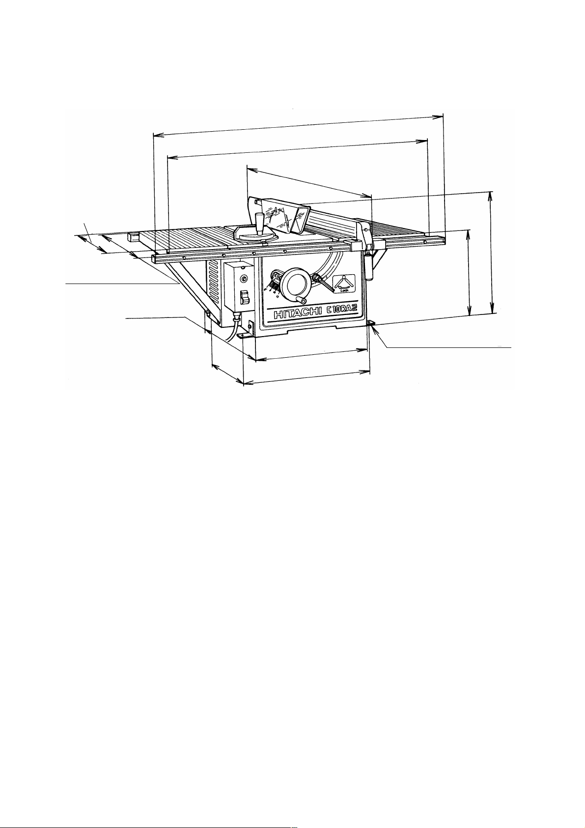
5-2. Outside View and External Dimensions
Table depth
500 mm
(19-11/16")
Rail depth 595 mm
(23-7/16")
455 mm
(17-29/32")
Overall width 965 mm (38")
Table width 864 mm (34")
Overall depth 825 mm
(32-1/2")
Table height
310 mm
(12-3/16")
Overall
height
410 mm
(16-1/8")
Mounting hole pitch
395 mm (15-9/16")
380 mm (14-31/32")
Mounting hole pitch
440 mm (17-5/16")
Fig. 3
8 mm (5/16") Dia. x 4 (pcs.)
Mounting hole diameter
--- 4 ---
Page 9

6. COMPARISONS WITH SIMILAR PRODUCTS
Maker
Model
Item
Outer diameter
Saw blade
Maximum
cutting
Inner diameter
0˚
(right angle)
45˚
(bevel)
Maximum dado cutter size
(diameter x width)
Maximum ripping capacity
Table dimensions
(width x depth)
Table dimensions with
extensions (width x depth)
Voltage, Current
Rated input
Motor
Max. output
No-load speed
Electric brake
HITACHI
C 10RA2/C 10RA
C
255 mm (10") 255 mm (10")
15.8 mm (5/8") 15.8 mm (5/8")
76 mm (3") 91 mm (3-9/16")
11 mm --- 63 mm (7/16" --- 2-1/2") 63 mm (2-1/2")
152 mm x 12 mm (6" x 1/2") ------
Right side 360 mm (14-5/32") Right side 305 mm (12")
Left side 400 mm (15-3/4") Left side 305 mm (12")
494 mm x 500 mm 680 mm x 560 mm
(19-7/16" x 19-11/16") (27" x 22")
864 mm x 500 mm
(34" x 19-11/16")
------
115 V, 15 A 115 V, 15 A
1,640 W ------
1,940 W (2.6 hp) ------
5,000 /min 4,600 /min
Provided Provided
Dust collection port
Machine dimensions
(width x depth x height)
Net weight
Standard equipment
O.D. 65 mm x I.D. 59 mm
(O.D. 9/16" x I.D. 5/16")
------
[C 10RA2]
965 mm x 825 mm x 410 mm
(38" x 32-1/2" x 16-1/8") 686 mm x 560 mmx 458 mm
[C 10RA] (27" x 22" x 18")
864 mm x 750 mm x 410 mm
(34" x 29-17/32" x 16-1/8")
[C 10RA2]
Net: 29 kg (64 lbs) Gross: 38 kg (84 lbs)
Net (with table saw stand): 38 kg (84 lbs)
Gross: 46 kg (101 lbs)
[C 10RA]
Net (with extension wing): 25.4 kg (56 lbs)
Gross: 29 kg (64 lbs)
18 kg (40 lbs)
255 mm (10") TCT 255 mm (10") TCT
saw blade (NT 36)
Set plate
••••••••••••••••••••••••••••••••••••••••
Wrench (22 mm)
•••••••••••••••••••••
•••••••••••••••••••••••••••••
Wrench (23 mm x 26 mm)
Elbow (chip extraction duct)
•••••••••••••••
•••••••••••••
1 saw blade
4 Rip fence
1 Miter gauge
1 Wrench (19 mm)
1 Wrench (13 mm x 22 mm)
••••••••••••••••••••••••••••••••••
••••••••••••••••••••••••••••••••••••••••
••••••••••••••••••••••••••••••••••••
•••••••••••••••••••••••••••••
••••••••••••••••
1
1
1
1
1
Optional accessories
Table saw stand (Code No. 314819) Table saw stand
Push stick (Code No. 314324) Porta table
Dado insert (Code No. 314325) Rip fence
Miter gauge
Dado head set
Ring (for use with dado head set)
--- 5 ---
Page 10

7. PRECAUTIONS IN SALES PROMOTION
In the interest of promoting the safest and most efficient use of the Model C 10RA2 Table Saw by all of our
customers, it is very important that at the time of sale, the salesperson carefully ensures that the buyer seriously
recognizes the importance of the contents of the Instruction Manual, and fully understands the meaning of the
precautions listed on the various caution plates attached to each machine.
7-1. Instruction Manual
Although every effort is made in each step of design, manufacture and inspection to provide protection against
safety hazards, the dangers inherent in the use of any electric tool cannot be completely eliminated. Accordingly,
general precautions and suggestions for the use of electric power tools, and specific precautions and suggestions
for the use of the table saw are listed in the Instruction Manual to enhance the safe and efficient use of the tool by
the customer. Salespersons must be thoroughly familiar with the contents of the Instruction Manual to be able to
offer appropriate guidance to the customer during sales promotion.
7-2. Precautions on the Name Plate
Each Model C 10RA2 is furnished with a Name Plate that lists the following precautions:
CAUTION
• For Safe operation, see Instruction Manual.
• Always wear eye protection.
• Do not use saw blade rated below 6000 rpm.
• Use guards with saw blade.
••••••••••••••••••••••••••••••••••••
••••••••••••••••••••••••••••••••••••
••••••••••••••••••••••••••••••••••••
••••••••••••••••••••••••••••••••••••
1
2
3
4
(1) Instruct the customer to read the Instruction Manual thoroughly prior to attempting to operate the machine.
(2) As cutting chips or sawdust flying into the eyes of the operator could result in loss of sight, it is absolutely
necessary to caution the customer to wear protective glasses whenever operating the machine.
(3) Instruct the customer never to use a saw blade with a rated maximum rotation speed of less than 6,000 /min.
If a saw blade with a rated maximum rotation speed of less than 6,000 /min is used, there is a danger that one
or more of the blade tips could fly off unexpectedly and cause serious injury to the operator or anyone else in
the immediate area.
(4) Instruct the customer to confirm without fail that all saw blade guards and other safety devices furnished with
the machine are properly mounted before attempting to operate the machine.
7-3. Warning Label (A)
WARNING
For Your Own Safety Read Instruction
Manual Before Operating Table Saw
1. Wear eye protection.
2. Use saw blade guard and spreader for every
operation for which it can be used, including all
through sawing.
3. Keep hands out of the line of saw blade.
4. Use a push stick when required.
5. Pay particular attention to instructions on
reducing risk of kickback.
6. Do not perform any operation freehand.
7. Never reach around or over saw blade.
This is mounted on the right side of the body shell.
Please instruct users to strictly observe the
contents of 1 to 7 in the warning label shown at left.
(Warning Label (A) is not provided on some areas'
models.)
N392456
--- 6 ---
Page 11

(1) Be sure to wear the protective glasses.
(2) Advise the user to use the saw blade guard and spreader when using the table saw. The saw blade guard
prevents the operator from touching the saw blade and the dislodging of workpieces. This should be
employed to ensure safety.
(3) Take care to keep the hands away from the saw blade.
(4) Explain the procedure for making and using the push stick (optional accessory) to the user. Details are
contained in the Instruction Manual (refer to page 17, 8. Work Helpers). Advise the user to use the push stick
when cutting a narrow workpiece vertically.
(5) If the workpiece dislodges, it may injure the operator.
Follow the dislodging preventive measures in the Instruction Manual. Advise the user to check that the
dislodging preventive claw (anti-kickback pawls) works correctly and the claw (anti-kickback pawls) edge is
sharp enough to bite into the workpiece before starting operation.
(6) Use both hands during cutting work. For cross cutting, hold the workpiece and miter gauge securely.
For vertical cutting, hold the workpiece and press it onto the rip fence surface securely by hand. These
precautions are fundamental to cutting work.
(7) Never get too close to the saw blade and be especially careful about the exposed rotating teeth.
7-4. Warning Label (B)
WARNING
For Your Own Safety Read Instruction
Manual Before Operating Table Saw
1. Never operate the power tool if the saw blade
guard does not function smoothly.
2. Never remove guard (including saw blade guard
spreader) from the tool body when you operate it (except
dado cutting.)
3. Always confirm that the rotary and saw blade
directions are the same.
4. The saw blade tilt lock handle must be locked
during all cutting operations.
5. Never operate to pull the workpiece back with the
saw blade turning.
N392464
This is mounted on the right side of the body shell.
Please instruct users to strictly observe the
contents of 1 to 5 in the warning label shown at left.
(1) The saw blade guard is designed to protect the operator from coming into contact with the saw blade during
operation of the tool.
(2) The saw blade guard and spreader are for safe operation. Do not operate the machine without the saw blade
guard and spreader (except for dado cutting).
(3) When mounting the saw blade, check that the saw blade's direction of rotation matches the machine's
direction of rotation.
(4) Be sure to lock the tilt lock handle to prevent tilting of the saw blade during operation.
(5) If the wood is pulled toward the operator during cutting, it may be repelled by the saw blade (kickback). Never
pull the wood toward the operator during cutting.
--- 7 ---
Page 12
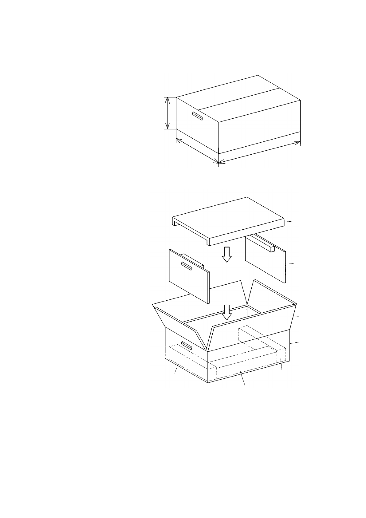
7-5. Package
The table saw Model C 10RA2 is divided into the main body and the saw blade guard sections before packing and
shipping. Therefore, buyers of this machine are required to perform some light assembly. Instruct customers to
carefully read the assembly procedure in the Instruction Manual.
Dimensions of cardboard box (mm)
370
690
1,045
Fig. 4
7-6 Packing
(1) Remove the saw blade guard, rip fence
and the miter gauge from the main body.
(2) Set the saw blade to the lower limit
Packing (B)
position.
(3) Disassemble the table saw stand.
(4) Pack the saw blade guard, rip fence and
table saw stand separately in each carton
box. Pack the miter gauge in the carton
box which is to be housed in the body
shell of the main body.
(5) Put the main body in the carton box.
(6) Put packing (A) and (B).
(7) Close the lids of the carton box and bind
them together.
Box for saw
blade guard
Packing (A)
Lid
Carton box
Box for rip
fence
Box for table
saw stand
Fig. 5
7-7. Related Laws and Regulations
The Model C 10RA2 has passed the C-UL standard. Therefore, the operator's safety is assured if it is operated
according to the Instruction Manual. The most important thing is to familialize the user with the machine, so
advise the user on correct operation and thus ensure the user's safety.
Misoperation will cause a serious accident. Please be very careful in advising the user.
--- 8 ---
Page 13
8. PRECAUTIONS ON OPERATION
8-1. Unpacking
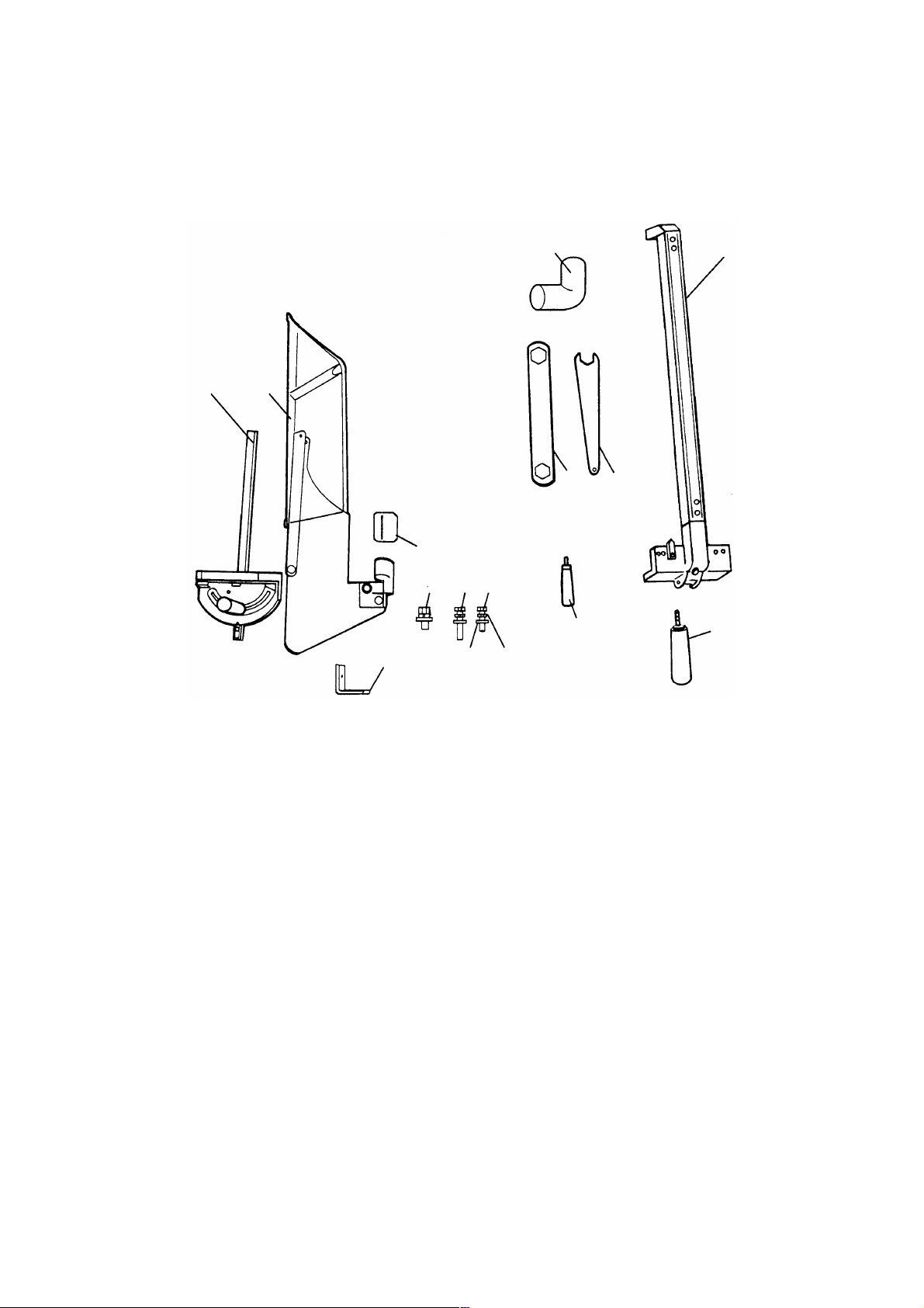
The parts illustrated in Fig. 6 are packaged together with the tool.
When unpacking, carefully confirm that all parts are accounted for.
Refer to the instructions packed in the carton box for the components of the table saw stand.
3
1
2
6
7
14
15
13
12
5
910
11
4
8
Fig. 6
1. Miter gauge (1 piece)
2. Saw blade guard and spreader assembly (1 piece)
3. Elbow (1 piece)
4. Rip fence (1 piece)
5. Hex. wrench (1 piece)
6. Wrench (1 piece)
7. Handle bar (1 piece)
8. Grip (1 piece)
9. 6 x 90 mm Bolt (1 piece)
10. 6 x 110 mm Bolt (1 piece)
11. 6 mm Spring washer (2 pieces)
12. 6 mm Flat washer (2 pieces)
13. 8 x 20 mm Bolt (with/washers) (4 pieces)
14. Set plate (4 pieces)
15. Cushion (1 piece)
--- 9 ---
Page 14

8-2. Assembly
WARNING: To avoid an accident or personal injury, always confirm that the switch is turned OFF and
the power plug has been disconnected from the receptacle before assembly of this tool.
8-2-1. Assembly of the Handle Bar
The handle allows faster turning of the wheel.
When properly assembled, it will rotate freely but with only a
small amount of play,
Wheel
(1) Tighten the screw of the handle until it hits against the
wheel.
Handle bar
(2) Securely tighten the handle bar nut with a wrench.
Fig. 7
8-2-2. Installing of the Rip Fence
CAUTION: The rip fence must be aligned parallel to the saw blade to minimize kickback.
The rip fence can be conveniently used to cut a workpiece
Supprot
into different pieces of precise width or into parallel pieces.
Rear rail
It can be mounted on either the right or left side of the table.
(1) Tighten the screw of the grip.
(2) Catch the hook of the support in the bottom part of the
rear rail.
Grip
Width
body
Front rail
(3) Lower the rip fence in the arrow direction, and fit the part
of the width body and support to the groove of the front
Fig. 8
8-2-3. Assembly of the Miter Gauge
Miter gauge groove
Sheet bar
Miter gauge
Fig. 9
and rear rail.
(4) Confirm that the rip fence is moved right and left and it
moves smoothly.
The miter gauge is convenient for cutting long or angular
pieces which are difficult to work on with the rip fence. It
can be mounted on either the right or left side of the table.
Align the sheet bar of miter gauge with the miter gauge
groove and slide it in the direction indicated by the arrow
through the front of the table.
--- 10 ---
Page 15

8-2-4. Mounting and Adjusting the Saw Blade Guard Assembly
Up
Wheel
Guard bracket
Saw blade
Down
Loosen
Tighten
Tilt lock
handle
Fig. 10-a
Spreader
6 x 90 mm Bolt
6 x 110 mm Bolt
Fig. 10-b
CAUTION: The saw blade guard and spreader assembly
must be aligned properly to the saw blade in
order to prevent kickback.
Mount the saw blade guard assembly, which includes the
spreader and anti-kickback pawls (see Fig. 10-d).
(1) Mounting the spreader
1 Loosen the saw blade tilt lock handle, move the saw blade
tilting mechanism to the left and set the saw blade to 0˚ by
means of the stopper. Tighten the saw blade tilt lock
handle to lock it in position.
2 Turn the wheel fully clockwise and set the saw blade to the
maximum cutting height (see Fig. 10-a).
3 Put a 6 mm spring washer and a D13 flat washer on to the
6 x 90 mm and 6 x 110 mm bolts.
4 Tentatively fasten the spreader on the rear section of the
body using the cushion and two 6 mm bolts mentioned
above (see Fig. 10-b and Fig. 10-d). (The guard bracket
Saw blade
Straight-edge
Less than
1/2" (12.7 mm)
Saw
blade
Fig. 10-c
Anti-kickback
pawl
Spreader
Spreader
6 x 16 mm
Bolts
must be attached to the spreader in advance.)
(2) Adjusting the spreader
1 Use a straight-edge to align the spreader with the saw
blade (see Fig. 10-c).
Tighten the two 6 x 16 mm bolts (see Fig. 10-d) with a
wrench to lock the spreader.
2 Check clearance between saw blade tip and the spreader.
It should be less than 1/2" (12.7 mm) at all positions. If not,
loosen the two 6 x 16 mm bolts securing the spreader to
the guard bracket with a wrench and move the spreader up
and down. After adjustment of the spreader is complete,
firmly retighten the two 6 x 16 mm bolts with a wrench (see
Fig. 10-d).
Cushion
Fig. 10-d
--- 11 ---
Page 16

8-2-5. Mounting the Table Insert
Table
5 mm Machine screws
Table insert
The table insert is mounted to the table with two 5 mm machine
screws.
CAUTION: The table insert must be in place and securely
fastened at all times.
Fig. 11
8-2-6. Mounting the Elbow (Chip Extraction Duct) (Standard Accessory)
Connect a 65 mm (2-9/16") hose from a dust collector to the
chip extraction duct to suck cutting chips away. Mount the chip
extraction duct on the chip discharge outlet at the rear of the
body.
Elbow (chip extraction duct)
Fig. 12
8-3. Adjustment
The tool is accurately adjusted before shipping from the factory.
Check the following settings and readjust them if necessary in order to obtain the best results in operation.
WARNING: To avoid an accident or personal injury, always confirm that the switch is turned OFF and
the power plug has been disconnected from the receptacle before adjustment of this tool.
8-3-1. Adjustment of Saw Blade parallel to Miter Gauge Groove
This is probably the most difficult of the adjustments. Before shipment from the factory this adjustment was made
but it should be rechecked and readjusted if necessary.
CAUTION: The adjustment must be correct or kickback could result and accurate cuts could not be
made.
Saw blade
(1) Loosen the saw blade tilt lock handle by turning it
counterclockwise. Move the saw blade tilting mechanism to
the left and set the saw blade to 0˚ with the stopper.
Down
(2) Turn the wheel fully clockwise and set the saw blade to the
Up
Tighten
Wheel
Fig. 13-a
Loosen
Tilt lock handle
maximum cutting height (see Fig. 13-a).
(3) Select a tooth on the saw blade which is bent to the right.
(4) Mark that tooth with a pencil or permanent marker.
(5) Set the miter gauge to 90˚ and tighten the clamp handle (B)
to lock it in that position. Place the miter gauge in the left
Clamp
handle (B)
Bar
Saw blade
hand miter gauge groove in the table top (see Fig. 13-b).
(6) Rotate the saw blade to bring the marked tooth to the front
and about 12.7 mm (1/2") above the table top.
Miter
gauge
(7) Place a bar or square flat against the miter gauge.
(8) Move the bar or square toward the saw blade until it just
touches the tip of the marked saw blade tooth.
Fig. 13-b
--- 12 ---
Page 17

Clamp
handle (B)
Miter
gauge
Bar
Saw blade
(9) Without disturbing the bar clamped to the miter gauge,
move the miter gauge to the center of the saw blade.
(10) Rotate the marked tooth to the rear and slide the miter
gauge rearward until the clamped bar is closest to the tip of
the marked saw blade tooth (see Fig. 13-c).
M6 x 10
M6 x 20
seal lock
screw
6 mm Flat
head screw
seal lock
screw
Fig. 13-c
8-3-2. Adjusting the 90˚ and 45˚ Positive Stops
Saw blade
(11) If the bar just touched the tooth when the gauge was in the
front position, it should just touch the tooth in the rear
position.
Likewise, if there was some clearance between the bar and
the tooth tip at the front, the same clearance should be at
the rear.
(12) If the front and rear clearance are not identical,
1 Remove the miter gauge.
2 Loosen the four 6 mm flat head screws.
3 Move the body and adjust it so that a bar placed on the
miter gauge has the same clearance between the front
and the rear of the saw blade.
4 Tighten the four 6 mm flat head screws.
The tool is equipped with positive stops for rapid and accurate
positioning of the saw blade at 90˚ and left bevel 45˚ to the
Up
Wheel
Down
Tighten
Fig. 14-a
Square
Fig. 14-b
Needle pointer
5 mm Machine screw
Loosen
Tilt lock
handle
Saw blade
table.
Check and adjust the positive stops with the following
procedures.
(1) To adjust positive stop at 90˚
1 Turn the wheel fully clockwise and set the saw blade to the
maximum cutting height.
2 Loosen the saw blade tilt lock handle and move the saw
blade tilting mechanism to the left until it hits against the
stopper. Then tighten the saw blade tilt lock handle (see
Fig. 14-a).
3 Use a square to check that the saw blade is at precisely
90˚ (see Fig. 14-b).
4 If the saw blade is not at precisely 90˚, loosen the saw
blade tilt lock handle by turning it counterclockwise.
Loosen the M6 x 20 seal lock screw (see Fig. 13-c) a few
turns and move the saw blade tilting mechanism until the
blade is 90˚ to the table (see Fig. 14-b).
Fig. 14-c
5 Tighten the saw blade tilt lock handle after adjustment.
6 Loosen the 5 mm machine screw and set the needle
pointer to 0˚. On completion of adjustment, recheck the
90˚ angle of the saw blade and table (see Fig. 14-c).
--- 13 ---
Page 18

Saw blade
(2) To adjust the positive stop at left bevel 45˚
1 Turn the wheel fully clockwise and set the saw blade to the
Down
Up
Loosen
Tighten
Wheel
Fig. 15-a
Saw blade
Fig. 15-b
8-3-3. Adjustment of the Rip Fence
Support
Rip fence
Tilt lock
handle
45˚ Gauge
maximum cutting height.
2 Loosen the saw blade tilt lock handle and move the saw
blade tilting mechanism to the right until it hits against the
stopper. Then tighten the saw blade tilt lock handle
(see Fig. 15-a).
3 Use a 45˚ gauge to check that the saw blade is at a left
bevel 45˚ (see Fig. 15-b).
4 If the saw blade is not at a left bevel 45˚, loosen the saw
blade tilt lock handle. Loosen the M6 x 20 seal lock screw
(see Fig. 13-c) a few turns and move the saw blade tilting
mechanism until the blade is at left bevel 45˚ to the table
(see Fig. 15-b).
5 After adjustment, tighten the saw blade tilt lock handle.
6 On completion of adjustment, recheck the left 45˚ bevel of
the saw blade to the table.
Before shipment from the factory the saw blade is set parallel to
the miter gauge groove and the rip fence is adjusted parallel to
Front
rail
Miter gauge
groove
Grip
Fig. 16-a
Parallel bracket
6 mm Hex. hd. bolt
the miter gauge groove. Check and adjust the parallel of the rip
fence by the following procedures. In order to accurate work
and prevent kickback when ripping. Before adjustment of rip
fence, check and adjust slider (It is assembled under the width
body.) to engage with the groove on front rail.
(1) Raise the grip to the upside and release the fixation of the rip
fence (see Fig. 16-a).
(2) Position the rip fence at one edge of the miter gauge groove.
(3) Lower the grip to the bottom and fix the rip fence. The edge
of the rip fence should line up parallel with the miter gauge
groove.
(4) If the edge of the rip fence is not parallel with the miter gauge
groove.
1 Loosen the four 6 mm hex. hd. bolts securing the parallel
bracket to the width body and support.
2 Raise the grip to the upside and release the fixation of the
rip fence.
Align the rip fence parallel to the miter gauge groove.
Grip
Width body
Fig. 16-b
Lower the grip to the bottom and fix the rip fence.
3 While holding the parallel bracket to prevent movement,
tighten the four 6 mm hex. hd. bolts previously loosened
(see Fig. 16-b).
--- 14 ---
Page 19

4 Raise the grip to the upside and release the fixation of the rip fence. Move and return the parallel bracket
adjacent to the miter gauge groove. Lower the grip to the bottom and fix the rip fence. And verify that the
parallel bracket is parallel to the miter gauge groove.
5 Repeat adjustment until it is parallel.
6 After adjustment, tighten four 6 mm hex. hd. bolts.
7 On completion of adjustment, recheck the rip fence is parallel with the miter gauge groove.
8-3-4. Adjustment of the Pointer
The pointer indicates the distance the rip fence is positioned away from the saw blade. The pointer should
indicate the accurate distance from the saw blade. Check and adjust the pointer with the following procedures.
NOTE: The pointer will need to be readjusted whenever a different thickness saw blade is installed.
Saw blade
Pointer
Rip fence
To adjust the pointer 0 setting.
(1) Raise the grip to the upside and release the lock on the rip
(2) Make sure that the pointer points to 0 on the scale provided
(3) If the pointer does not point to 0 on the scale,
Scale
5 mm
Grip
Machine screw
Fig. 17
8-3-5. Adjustment of the Miter Gauge
The miter gauge should be square to the saw blade.
fence. And move the rip fence to bring it into tight contact
with the side of the saw blade.
on the table.
1 Lower the grip to the bottom and lock the rip fence.
2 Loosen the 5 mm machine screw holding the pointer
(see Fig. 17).
3 Adjust the pointer to the 0 position and retighten the 5 mm
machine screw.
4 After adjustment, recheck to see that the pointer now points
to 0.
Check and adjust the miter gauge with the following procedures.
Square
Sheet bar
To adjust the pointer 0 setting.
(1) Loosen clamp handle (B) and place a square against both
the saw blade and the miter gauge. The pointer should
Miter gauge
Clamp
handle (B)
Saw
blade
indicate 90˚ on the protractor scale on the miter gauge.
(2) If the pointer does not indicate 0 on the miter gauge,
1 Tighten clamp handle (B).
2 Loosen the 5 mm machine screw on the sheet bar.
Protractor
scale
Pointer
5 mm
Machine screw
Fig. 18
3 Adjust the pointer to the 90˚ position and tighten the 5 mm
machine screw on the sheet bar (see Fig. 18).
4 After adjustment, recheck to see that the pointer now
indicates 0.
--- 15 ---
Page 20

8-4. Relation between Saw Blade and Spreader
t2=2.3 mm
The spreader bites into the workpiece kerf like a wedge to prevent the saw blade from being pressed by the
workpiece. Therefore, the spreader thickness needs to be larger than the saw thickness (t1).
However, if the spreader thickness is larger than the set width (W), a large resistance is applied to the feeding of
the workpiece, making operation impossible.
If a locally available saw blade is used, the above relation cannot be obtained, causing a defect in operation.
Therefore, it is important to advise the user to use only genuine Hitachi saw blades.
8-5. Overload Protective Device
This tool is provided with an overload protective device (thermal relay). If the workpiece feed speed is too fast or
the saw blade is dull, the overload protective device engages to stop power to the motor and protect it. In this
case, allow the motor to cool from 3 to 5 minutes and then press the reset switch to resume operation.
W
Fig. 19
The saw thickeness (t1), set width (tip width, W) and
t1
spreader thickness (t2) are set in the following relation to
prevent dislodging : W>t2>t1.
The spreader thickness of C 10RA2 is 2.3 mm. (Fig. 19)
8-6. Precautions on Using the Electric Brake
This machine is equipped with a electric brake to stop the blade's rotation when the switch is turned OFF. When
the switch is turned OFF, the rotation usually stops in 3 to 5 seconds. Should it take more than 15 seconds before
stopping, the machine should not be used. Instruct the customer to contact a Hitachi electric tool dealer for
inspection or repair if this occurs.
(1) Be sure to use carbon brushes designated for this machine (Code No. 999044). The use of any other carbon
brush will hinder performance of the electric brake.
(2) Should the electric brake fail to function, check the carbon brushes. If they wear below 5 mm (3/16") in length,
replace them. If the electric brake still does not function, it may be necessary to replace the armature ass'y,
etc.
--- 16 ---
Page 21

8-7. Extension Cords
The Instruction Manual contains a table of cord lengths and lead wire diameters. Select an appropriate extension
cord. If the lead wire diameter is too small compared with the cord length, it may cause considerable voltage
drop, resulting in lowered efficiency.
Use only three-wire extension cords which have three-prong grounding-type plugs and three-pole receptacles
which accept the saw's plug. Replace or repair a damaged or worn cord immediately.
Make sure your extension cord is in good condition. When using an extension cord, be sure to use one heavy
enough to carry the current your product will draw. An undersized cord will cause a drop in line voltage resulting
in loss of power and overheating. Table 4 shows the correct size to use depending on cord length and Name
Plate ampere rating. If in doubt, use the next heavier gauge. The smaller the gauge number, the heavier the
cord.
Check power cords and extension cords for loose or exposed wires and damaged insulation before using.
Repair or replace as needed before using the power tool.
NOTE: The lower the wire size number, the heavier the wire and the further it will carry current without a voltage
drop.
WARNING: Never connect this unit to an electrical power source until all operating instructions have
been read and understood.
Table 4. Minimum gauge for cord
Ampere rating
(on Name Plate)
Ext. cord length
25 ft. 14 A.W.G.
(7.5 m) (2.0 mm2)
50 ft. 12 A.W.G.
(15 m) (3.5 mm2)
15 A
Wire gauge size
A.W.G. (mm2)
--- 17 ---
Page 22

8-8. Cutting Work
Precautions on cutting work are provided in the Instruction Manual. Read them carefully and advise the user on
correct operation. In this section, important items and the items not described in the Instruction Manual are
explained to help you advise the user.
(1) For cutting work, be sure to use the saw blade guard and check that everything functions properly.
1 Check that the saw blade guard rises smoothly.
2 Remove wood chips in the guard and wipe off the swarf on the guard with a soft cloth.
3 Check that the dislodging preventive claw (anti-kickback pawls) works normally and is sharp at the tips.
4 Check that the screw fastening the spreader is not loose.
(2) When using the miter gauge and rip fence, be sure to secure them firmly before starting operation.
(3) Before starting operation, be sure to tighten the tilt lock handle for raising and tilting saw blade.
(4) Remove the swarf in the miter-gauge groove.
(5) Do not raise the saw blade excessively.
Saw blade
Workpiece
Fig. 20
(6) The standard precision values are provided in 10-5. Product Precision.
Advise the user to check the precision before starting cutting work. If the precision is insufficient, it may cause
dislodging of the workpiece or other unexpected accidents, resulting in poor cutting precision.
(7) The set nut securing the saw blade is naturally tightened.
Advise the user to check the set nut is firmly tightened before starting operation, and also to remove the plug
at this time.
(8) Use of work helpers.
Assembling and procedures for use of work helpers:
Work helpers are essential for safe operation. Give careful advice on this point. Many books are available on
the market relating to work helpers and use of table saws. Recommend the user to purchase such books.
Approx. 3.2 mm (1/8")
As shown in Fig. 20, raise the saw blade about
3.2 mm (1/8") above the workpiece to be cut.
Excessive raising may cause dislodging of the
workpiece.
--- 18 ---
Page 23

9. MAINTENANCE AND INSPECTION
WARNING: To avoid an accident or personal injury, always confirm that the switch is turned OFF and
that the power plug has been disconnected from the receptacle before performing any
maintenance or inspection of this tool.
9-1. Inspecting the Saw Blade
Always replace the saw blade immediately upon the first sign of deterioration or damage. A damaged saw blade
can cause personal injury and a worn saw blade can cause ineffective operation and possible overload to the
motor.
CAUTION: Never use a dull saw blade. When a saw blade is dull, its resistance to the hand pressure
applied by the tool handle tends to increase, making it unsafe to operate the power tool.
9-2. Inspecting the Carbon Brushes (Fig. 21 and Fig. 22)
The carbon brushes in the motor are expendable parts. If the carbon brushes become excessively worn, motor
trouble might occur. Therefore, inspect the carbon brushes periodically and replace them. Check the carbon
brushes after the first 50 hours of use for a new machine or after a new set of carbon brushes have been installed.
After the first check, examine them after about every 10 hours of use until such time that replacement is
necessary. When the carbon on either brush is worn to 5 mm (3/16") in length or if either spring or shunt wire is
burned or damaged in any way, replace both carbon brushes (see Fig. 21). If the carbon brushes are found to be
serviceable after removing, reinstall them in the same position as before. Also, keep the carbon brushes clean so
that they will slide smoothly within the brush holders. The carbon brushes can easily be removed after removal of
the brush caps (see Fig. 22) with a flatblade screwdriver.
Brush cap
Wear limit line
5 mm (3/16")
17 mm (43/64")
Fig. 21
Fig. 22
Motor
9-3. Inspecting the Mounting Screws
Regularly inspect each component of the power tool for looseness. Re-tighten mounting screws on any loose
part.
WARNING: To prevent personal injury, never operate the power tool if any components are loose.
--- 19 ---
Page 24

9-4. Inspecting the Saw Blade Guard for Proper Operation
Before each use of the tool, test the saw blade guard to assure that it is in good condition and that it moves
smoothly. Never use the tool unless the saw blade guard operates properly and unless it is in good mechanical
condition. Ensure the anti-kickback pawls are always sharp so they dig into the workpiece and avoid kickback. If
any damage has occurred, repair it promptly.
9-5. Regular Cleaning of the Saw Blade Guard
Wipe off saw dust attached to the inside of the see-through saw blade guard using a soft cloth. Do not use
solvent (gasoline, thinner etc.), solvents will damage plastic parts.
9-6. Storage
Confirm that the switch is turned OFF, that the power plug has been removed from the receptacle and that the
safety key has been removed and stored in a secure place, after operation of the saw has been completed.
When the saw is not in use, keep it stored in a dry place out of the reach of children.
9-7. Lubrication
Lubricate the following moving parts and rotating parts once a month to keep the saw in good operating condition
for a long time. Use of machine oil is recommended.
Oil supply points: Rotary and moving portion of wheel
9-8. Cleaning
Periodically remove chips and other waste material from the surface of the saw with a damp, soapy cloth.
To avoid a malfunction of the motor, protect it from contact with oil or water.
--- 20 ---
Page 25

10. PRECAUTIONS IN DISASSEMBLY AND REASSEMBLY
Please follow the precautions below for disassembly and reassembly procedures. The circled numbers in the
following figures and the [Bold] numbers in the descriptions below correspond to the item numbers in the Parts
List and exploded assembly diagrams.
CAUTION: Prior to attempting disassembly or replacement of the saw blade, ensure that the power cord
plug is disconnected from the power source.
10-1. Disassembly
A. Disassembly of the saw blade section
Tools required:
• Phillips head screwdriver
• 10 mm Wrench
• 22 mm Wrench (standard accessory)
• 23 x 26 mm Wrench (standard accessory)
--- 21 ---
Fig. 23
Page 26

(1) Remove the M6 x 110 Bolt [8] and M6 x 90 Bolt [11] using a 10 mm wrench, and remove the Saw Blade Guard
and Spreader Assembly (Blade Guard [3] and Spreader [24]).
(2) Remove the two M5 x 8 Machine Screws [59] and remove the Table Insert [58].
(3) Put the 22 mm wrench (standard accessory) on the Spindle Ass'y [201] to hold it. Then, put the 23 mm end of
the 23 x 26 mm wrench (standard accessory) on the Set Nut [99]. Turn it counterclockwise to remove the nut,
and remove Washer (A) [98], the TCT Saw Blade [704] and Washer (A) [98] in this order.
Refer to Fig. 28 for the part numbers of the 200 level.
B. Disassembly of the switch section
Tools required:
• Phillips head screwdriver
Fig. 24
(1) Remove the two D5 x 16 Tapping Screws [155] and remove the Switch plate [158]. Then, detach each lead
wire connected to the Circuit Breaker Switch [152] and Rocker Switch [159].
--- 22 ---
Page 27

(2) Remove the three D4 x 10 Tapping Screws [150] and remove the Switch Box [147]. Then, remove the two D4
x 8 Pan Hd.Tapping Screws [156] and detach the ground wire (green/yellow).
C. Disassembly of the motor and wheel sections
Tools required:
• Phillips head screwdriver
• Flatblade screwdriver
• 3 mm Hexagon bar wrench
• 10 mm and 12 mm Wrenches
• Plastic hammer
Fig. 25
--- 23 ---
Page 28

(1) Turn the Wheel [131] counterclockwise and move the motor to the lower limit position. Turn the Tension
Handle [130] counterclockwise to loosen and tilt the motor at an angle of 45 degrees. Turn the Tension
Handle [130] clockwise to tighten. Then, turn the body (Table [67] surface upside down.)
(2) Remove the two Brush Caps [220] and remove the two Carbon Brushes [221].
(3) Remove the four M5 x 30 Machine Screws [225], and remove the Housing Ass'y [222] (including the Stator
[218]), Baffle [215], and Armature Ass'y [212] in this order.
(4) Hold the Strain Relief [227] with the pliers and pull it out from the Housing Ass'y [222].
(5) Remove the two D5 x 60 Tapping Screws [216]. Then, detach the lead wire of the Stator [218] from the Brush
Holder [223], and the ground wire connector on the Stator [218]. And, while lightly striking the mounting
surface of the Bracket [211] of the Housing Ass'y [222] with the plastic hammer, draw out the Stator [218].
(6) Loosen the two M6 x 6 Hex. Socket Set Screws [106] securing the Anchor Block [107] and the two M6 x 6
Hex. Socket Set Screws [87] securing Bevel Gear (A) [74]. Remove the Wheel [131], the M 9.5 Flat Washer
[133], the Regulating Bolt [119], the 57L Compression Spring [118], the M16 Flat Washer [117], the 20L
Compression Spring [116], the M9.5 Flat Washer [108], the Anchor Block [107] and Bevel Gear (A) [74].
(7) Remove the M8 x 16 Bolt (with/Washers) [109] using a 12 mm wrench, and remove the Pointer Bracket [136]
(including the Needle Pointer [139]).
(8) Turn the Tension Handle [130] counterclockwise to loosen, and remove it.
(9) Loosen the M6 Nut [115] using a 10 mm wrench, and remove the M6 x 25 Flat Washer [129], the Spacer
[114], and the M6 x 35 Special Bolt [110].
Refer to Fig. 28 for the part numbers of the 200 level.
--- 24 ---
Page 29

D. Disassembly of the body and spindle sections
Tools required:
• Pillips head screwdriver
• 3 mm Hexagon bar wrench
• 8 mm, 10 mm and 13 mm Wrenches
• Plastic hammer
Fig. 26
(1) Remove the four M6 Nuts [105] using a 10 mm wrench, and remove the Body [92] from the Table [67].
(2) Remove the four M6 x 12 Machine Screws [112], and remove the Bracket [113].
(3) Remove the five D5 x 10 Tapping Screws [100], and remove the Blade Guard [101].
(4) Remove the M6 x 12 Machine Screw [97], and remove the Guard [95].
(5) Hold the Screw Bar [90] using an 8 mm wrench, and remove the M6 Special Nut Chuck [94] with a 10 mm
wrench.
(6) Slide the Bracket [211] upward (in the direction of the arrow in Fig. 26) and loosen the two M6 x 6 Hex. Socket
Set Screws [87]. Remove the M8 x 14.3 Flat Washer [88] and Bevel Gear (B) [89] from the Screw Bar [90].
(7) Remove the four M6 x 35 Bolts [78] using a 10 mm wrench, and remove the Slide Bracket [76] and Bracket
[211].
--- 25 ---
Page 30

(8) Remove the four M4 x 12 Machine Screws [203], and remove the Bearing Retainer [205].
(9) Remove the Spindle Ass'y [201] by striking the Bracket [211] with a plastic hammer.
(10) Hold the Screw Bar [90] using an 8 mm wrench, and remove the M8 Nut Chuck [91] with a 13 mm wrench.
Remove the Screw Bar [90] from the Bracket [211].
(11) Loosen the eight M8 x 20 Bolts (with Washers) [153] which fix Extension Supporter (L) [142] and Extension
Supporter (R) [154] with a 13 mm wrench and remove them.
(12) Remove the four M6 x 12 Bolts (with Washers) [122] using a 10 mm wrench, and remove the Body Shell
[123] from the Table [67].
Refer to Fig. 28 for the part numbers of the 200 level.
E. Disassembly of the rip fence section (fence ass'y)
Tools required:
• Phillips head screwdriver
• Pliers
• 5 mm Hexagon bar wrench
Fig. 27
(1) Loosen the two M6 x 16 Hex. Socket Hd. Bolts [40] which fix the Support [35] to the Parallel Bracket [42] with
a 5 mm hexagon bar wrench to remove the Support [35]. Be careful not to make the 57L Compression Spring
[36] fly out of the Support [35].
(2) Extract the Locking Rod [39] together with the 5/16" x 5/8" Flat Washer [37] being careful not to lose it.
(3) Loosen the two M6 x 16 Hex. Socket Hd. Bolts [40] which fix the Width Body [46] to the Parallel Bracket [42]
with a 5 mm hexagon bar wrench to remove the Width Body [46].
(4) Loosen the M5 x 12 Machine Screw [47] and remove the Rubber Stopper [161].
--- 26 ---
Page 31

Motor Parts
Fig. 28
--- 27 ---
Page 32

10-2. Reassembly
Perform reassembly in reverse order of disassembly while observing the following precautions.
(1) Prior to reassembly, measure the insulation resistance of the armature ass'y, stator ass'y, switch and other
electrical components with a DC 500 V Megohm Tester, and confirm that the insulation resistance of each part
is more than 5 MΩ.
(2) Dielectric strength test
After testing the insulation resistance, apply 1,200 volts between the blade of the Power Cable [151] and the
Body Shell [123] for one second with the Rocker Switch [159] ON, to check that no dielectric breakdown will
take place.
(3) No-load current value
The figures indicated below are the no-load current values after the machine is operated without load for 30
minutes.
No-load current (max.): 6.2 A at AC single phase 115 V, 60 Hz
(4) When assembling the Slide Plate [75], see Fig. 29 for the direction in which it is mounted on the Body [92].
Thoroughly wipe off the old grease on the sliding portion between the Slide Plate [75], and the Slide Bracket
[76] and Bracket [211].
Then apply two grams of motor grease No. 29 (Code No. 930035) there. Thoroughly wipe off the old grease in
the gear box of the Bracket [211], and apply two grams of motor grease No. 29 (Code No. 930035) to the
Needle Bearing [210]. Also thoroughly wipe off the old grease on teeth of the Helix Gear [208] in the Spindle
Ass'y [201], pinion of the Armature Ass'y [212], thread portion of the Screw Bar [90], and teeth of Bevel Gear
(A) [74] and Bevel Gear (B) [89]. Then apply motor grease No. 29 (Code No. 930035).
Refer to Fig. 28 for the part numbers of the 200 level.
6
8.5
Mount the slide plate with the 8.5 mm
side facing the motor.
Motor
Fig. 29
--- 28 ---
Page 33

10-3. Wiring
Wiring should be performed as shown in Fig. 30. Please note that incorrect wiring will result in a failure in
rotation.
(1) Wiring diagram
Rocker
switch
Power
cable
Green (ground)
Black
White
(2) Lead wire arrangements
Lead
wire
(black)
Motor
cable
Circuit
breaker
switch
White
Green (ground)
Black
Red
Black
Red
White
Green (ground)
Fig. 30
Faston
terminal
Blue
Tab
terminal
Motor
cable
Stator
core outer
circumference
Break coil
Stator coil
Stator
ass'y
Circuit
breaker
switch
Black
Rocker
switch
Armature
ass'y
Black
White
Green (ground)
Power
cable
Fig. 31
When connecting each lead wire to the circuit breaker, and rocker switch, the faston terminals must be completely
inserted into the corresponding tab terminals.
--- 29 ---
Page 34

10-4. Adjustments
After disassembly and reassembly, the following parts require adjustment.
After being disassembled and reassembled, the affected items should be adjusted. For adjustment, see the
adjusting method described in 8-3. Adjustment on page 12.
(1) Parallel alignment of the saw blade and the miter-gauge groove
(2) Saw blade squareness and tilting 45˚ stopper position
(3) Parallel alignment of the rip fence and the miter-gauge groove
(4) Pointer position of the rip fence
(5) Squareness between the miter gauge and the saw blade
(6) Position of the spreader with respect to the saw blade (see 8-2-4 (2) Adjusting the spreader on page 11.)
10-5. Product precision
After the reassembly is completed, check the precision of the product.
(Unit: mm/mm)
Item
Run out of dummy disc 0.38/230
Squareness between dummy disc and table upper surface 0.4/60
Parallelism between dummy disc and miter-gauge groove 0.4/200
Parallelism between dummy disc and rip fence 1.0/200
--- 30 ---
Page 35

11. REPAIR GUIDE
No Problem Possible cause
Low cutting accuracy
1
--- poor squareness of
cut surface
Table
(Note) Unit: mm/mm
Fig. 32
Saw blade
Saw blade
Squareness
0.4/60
Parallelism
1.0/200
a) Because of poor
squareness between
the table and saw
blade, the saw blade
enters the material at
a slant.
b) Large run out of saw
blade
(Large vibration)
c) Poor parallelism of
table upper surface
d) Poor parallelism
between the table and
the extension wing
e) Poor parallelism
between the mitergauge groove and
saw blade
Factory rated
value
0.4/60
(Dummy disc)
(Fig. 32)
0.38/230
(Dummy disc)
1.0 /200
or under
1.5/200
or under
0.4/200
(Dummy disc)
Remedy
• Readjust the squareness of the
saw blade using the M6 x 20
Seal Lock Screw [61].
• Replace the Saw Blade [704].
• Check Washer (A) [98] for
dents, etc. If any, remove with
a file.
• Replace Washer (A) [98].
• Replace the Table [67].
• Loosen the M8 x 20 Bolt (W/
Washers) [153], M6 x 35 Hex.
Socket Hd. Cap Bolt [73] and
readjust the parallelism
between the Table [67], and
Extension Wing (R) [71] and
Extension Wing (L) [63].
• Replace Extension Wing (R)
[71] or Extension Wing (L) [63].
• Loosen the M6 x 25 Flat Hd.
Screw [60], and readjust the
parallelism between the mitergauge groove and the saw
blade.
Table
Rip fence
(Note) Unit: mm/mm
Fig. 33
f) Poor parallelism
between the rip fence
and saw blade
g) A too fast cutting
speed causes the saw
blade to deflect and
results in low
accuracy.
h) Excessive force is
applied because of a
dull saw blade.
i ) Deformation of the
material such as a
curvature or bend
causes the material to
move during cutting.
1.0/200
(Dummy disc)
(Fig. 33)
------
------
------
• Loosen the M6 x 16 Hex.
Socket Hd. Bolt [40], and
readjust the parallelism
between the rip fence and the
saw blade.
• Slow down the cutting speed.
(Proper speed is 7 seconds for
50 mm rectangular lumber.)
• Sharpen the Saw Blade [704].
• Replace the Saw Blade [704].
• Correct the curvature or bend
by planing the material, and cut
again.
--- 31 ---
Page 36

No Problem Possible cause
Factory rated
value
Remedy
Poor cut surface
2
Parallelism a =
0.02/63
a
Washer (A)
(Note) Unit: mm/mm
Fig. 34
The saw blade locks
3
up.
a) Large run out of saw
(Dummy disc)
• Same as item No. 1, b).
blade (Large run out
results in poor cut
a
grain.)
b) Poor parallelism of
washer (A) due to
Washer (A)
(Fig. 34)
• Remove dents or flaws on
Washer (A) [98], or replace.
dents or flaws
c) Cutting speed too fast.
d) During cutting, the
material becomes
------
------
• Slow down the cutting speed.
• Eliminate the curvature, bend,
etc. in the material by planing.
rough because of its
curvature, bend, etc.
a) Cutting speed too fast.
b) Thin extension cord
------
------
• Slow down the cutting speed.
The usable extension cords are
as follows:
Ampere rating 15
c) Excessive force is
applied because of a
dull saw blade.
d) Wrong selection of
saw blade
e) During cutting, the
material binds the saw
blade because of a
deformation such as
curvature and bend.
------
------
------
Ext. cord length Wire gauge size
25 ft. 14 A.W.G.
(7.5 m) (2.0 mm
50 ft. 12 A.W.G.
(15 m) (3.5 mm
2
)
2
)
• Shapen the Saw Blade [704].
• Replace the Saw Blade [704].
• Use a genuine Hitachi saw
blade.
• The higher the number of teeth
of a saw blade, the more
cutting resistance increases.
Where a saw blade with many
teeth is used, cut slowly.
• Eliminate the curvature, bend,
etc. in the material by planing.
--- 32 ---
Page 37

No Problem Possible cause
Factory rated
value
Remedy
The saw blade won't
4
turn even if the switch
is turned on.
Slow saw blade
5
rotation.
The saw blade speed is
less than 5,000 /min.
a) Power cord is not
connected to the
power outlet.
b) Wear of the carbon
brushes has exceeded
the wear limit (5 mm).
c) Switch failure
d) The circuit breaker
switch activated.
a) Power voltage lower
than rated voltage.
------
------
------
------
4,500 --- 5,500 /min
• Check the power voltage.
• Plug the power cord into the
outlet.
• Check the Carbon Brushes
[221].
• Replace the Carbon Brushes
[221].
• Check the Rocker Switch [159]
or the Circuit Breaker Switch
[152] for continuity.
• Replace the Rocker Switch
[159] or the Circuit Breaker
Switch [152].
• Press the reset button after 2 to
3 minutes.
• Check the power voltage.
• Check if the extension cord
used is nonstandard. The
usable extension cords are as
follows:
Fast saw blade speed.
6
The saw blade speed is
more than 5,000 /min.
a) Power voltage higher
than rated voltage.
4,500 --- 5,500 /min
Ampere rating 15
Ext. cord length Wire gauge size
25 ft. 14 A.W.G.
(7.5 m) (2.0 mm
50 ft. 12 A.W.G.
(15 m) (3.5 mm
• Check the power voltage.
2
)
2
)
--- 33 ---
Page 38

12. STANDARD REPAIR TIME (UNIT) SCHEDULES
MODEL 10 20 30 40 60 70 min.
Fixed
Variable
50
Work Flow
C 10RA2
Extension
Wing (L)
Extension
Wing (R)
General Assembly
Blade Guard
Ass'y
Spreader
Switch plate
Other: 10 min.
0 min.
Circuit Breaker
Switch
Switch Plate
Rocker Switch
Power Cable
Spreader
TCT Saw Blade
Washer (A)
Blade Guard
Switch Box
Pivot Support
Anchor Block
Regulating Bolt
Wheel
Slide Bracket
Compression
Spring
Segment Gear
Hitachi Label
Screw Bar
Bevel Gear (B)
Bracket Body
Body Shell
Table
Carbon Brush Housing
Armature Ass'y
Bracket
Spindle Ass'y
Ball Bearing
(6204VV)
Helix Gear
Ass'y
Stator
--- 34 ---
Page 39

Assembly Diagram for C 10RA2
--- 35 ---
Page 40

Assembly Diagram for C 10RA2
--- 36 ---
Page 41

PARTS
ITEM
CODE NO. DESCRIPTION
No.
1 318-086 BLADE GUARD ASS’Y 1 INCLUD.2-25
2 314-474 NUT CHUCK M6 1
3 314-479 BLADE GUARD 1
4 314-476 SELF-LOCKING RING 2
5 949-644 BOLT M6X40 (10 PCS.) 1
6 314-477 ARM 1
7 314-478 RIVET 2
8 318-088 BOLT M6X110 1
9 949-455 SPRING WASHER M6 (10 PCS.) 2
10 949-432 BOLT WASHER M6 (10 PCS.) 2
11 318-089 BOLT M6X90 1
12 314-483 GUARD BRACKET 1
13 949-556 NUT M6 (10 PCS.) 2
14 318-090 CUSHION 1
15 314-480 BUSHING 2
16 949-613 BOLT M6X16 (10 PCS.) 2
17 949-455 SPRING WASHER M6 (10 PCS.) 2
18 973-361 WASHER 2
19 314-476 SELF-LOCKING RING 2
20 314-444 KICK BACK PAWL 2
21 314-445 BUSHING 2
22 949-870 ROLL PIN D4X22 (10 PCS.) 1
23 314-447 SPRING 1
24 318-092 SPREADER 1
25 314-446 ROLL PIN 1
26 318-093 RIP FENCE ASS’Y 1 INCLUD.27-57,161
27 318-094 TAPPING SCREW D5X25 1
28 314-555 SEGMENT GEAR 1
29 318-095 REAR CLAMP 1
30 318-096 SPRING PIN 1
31 318-097 SLIDER (REAR) 1
32 318-098 HEX. NUT M4 2
33 318-133 PAN HD. SCREW M5X25 1
34 318-100 COUNTER HD. SCREW M4X20 2
35 318-101 SUPPORT 1
36 314-537 COMPRESSION SPRING 57L 1
37 318-102 FLAT WASHER 5/16"X5/8" 1
38 318-103 E-RING 1
39 318-104 LOCKING ROD 1
40 949-755 HEX. SOCKET HD. BOLT M6X16 (10 PCS.) 4
41 317-627 FLAT WASHER 1/4"X5/8" 4
42 318-105 PARALLEL BRACKET 1
43 317-567 ROUND WASHER HD. SCREW M5X8 1
44 318-106 NEEDLE POINTER 1
45 318-107 COUNTER HD. SCREW M4X12 4
46 318-108 WIDTH BODY 1
47 949-237 MACHINE SCREW M5X12 (10 PCS.) 1
48 949-431 BOLT WASHER M5 (10 PCS.) 1
49 318-096 SPRING PIN 1
50 318-111 SLIDER (FRONT) 2
51 318-098 HEX. NUT M4 4
: ALTERNATIVE PARTS
*
--- 37 ---
NO.
USED
REMARKS
C 10RA2
----
7
99
Page 42

PARTS
ITEM
7
CODE NO. DESCRIPTION
No.
52 318-113 CLAMPER 1
53 318-114 RUBBER BUSHING 1
54 318-115 ECCENTRIC SHAFT 1
55 949-558 NUT M8 (10 PCS.) 1
56 318-116 CLAMP BOLT 1
57 318-117 GRIP 1
58 314-484 TABLE INSERT FOR SAW BLADE 1
59 949-235 MACHINE SCREW M5X8 (10 PCS.) 2
60 949-342 FLAT HD. SCREW M6X25 (10 PCS.) 4
61 314-486 SEAL LOCK SCREW M6X20 1
62 318-118 MACHINE SCREW (W/WASHERS) M6X20 6
63 318-119 EXTENSION WING (LEFT) 1
64 318-120 SCALE (LEFT) 1
65 318-121 SCALE (CENTER) 1
66 314-490 SEAL LOCK SCREW M6X10 1
67 318-122 TABLE 1
68 318-123 RAIL 2
69 318-124 SIDE COVER (RIGHT) 2
70 318-125 SCALE (RIGHT) 1
71 318-126 EXTENSION WING (RIGHT) 1
72 318-127 SIDE COVER (LEFT) 2
73 318-128 HEX. SOCKET HD. CAP BOLT M6X35 16
74 314-512 BEVEL GEAR (A) 1
75 314-513 SLIDE PLATE 2
76 314-514 SLIDE BRACKET 1
77 949-455 SPRING WASHER M6 (10 PCS.) 4
78 949-803 BOLT M6X35 (10 PCS.) 4
79 315-042 MITER GAUGE ASS’Y 1 INCLUD.80-86
80 314-505 CLAMP HANDLE (B) 1
81 314-506 FLAT WASHER M6.4 1
82 314-507 MITER GAUGE 1
83 949-234 MACHINE SCREW M5X6 (10 PCS.) 1
84 314-509 ANGLE POINTER 1
85 314-510 PIN 1
86 314-511 SHEET BAR 1
87 967-469 HEX. SOCKET SET SCREW M6X6 4
88 314-516 FLAT WASHER M8X14.3 1
89 314-517 BEVEL GEAR (B) 1
90 314-518 SCREW BAR 1
91 314-519 NUT CHUCK M8 1
92 314-520 BODY 1
93 314-521 FLAT WASHER M6.4X12.7 1
94 314-522 SPECIAL NUT CHUCK M6 1
95 314-523 GUARD 1
96 949-455 SPRING WASHER M6 (10 PCS.) 1
97 949-255 MACHINE SCREW M6X12 (10 PCS.) 1
98 314-454 WASHER (A) 2
99 318-130 SET NUT 1
100 317-352 TAPPING SCREW D5X10 5
101 314-526 BLADE GUARD 1
102 314-527 FLAT WASHER M8X15 2
----
99
: ALTERNATIVE PARTS
*
NO.
USED
--- 38 ---
C 10RA2
REMARKS
Page 43

PARTS
ITEM
CODE NO. DESCRIPTION
No.
103 314-528 PIVOT SUPPORT 2
104 949-455 SPRING WASHER M6 (10 PCS.) 4
105 949-556 NUT M6 (10 PCS.) 4
106 967-469 HEX. SOCKET SET SCREW M6X6 2
107 314-533 ANCHOR BLOCK 1
108 314-534 FLAT WASHER M9.5 1
109 307-410 BOLT (W/WASHERS) M8X16 (BLACK) 1
110 314-529 SPECIAL BOLT M6X35 1
111 949-455 SPRING WASHER M6 (10 PCS.) 4
112 949-255 MACHINE SCREW M6X12 (10 PCS.) 4
113 314-530 BRACKET 1
114 314-531 SPACER 1
115 949-556 NUT M6 (10 PCS.) 1
116 314-535 COMPRESSION SPRING 20L 1
117 314-536 FLAT WASHER M16 1
118 314-537 COMPRESSION SPRING 57L 1
119 314-538 REGULATING BOLT 1
120 949-518 ROLL PIN D3X18 (10 PCS.) 1
121 973-361 WASHER 4
122 996-577 BOLT (W/WASHERS) M6X12 (BLACK) 4
123 314-539 BODY SHELL 1
124 WARNING LABEL (B) 1
125 WARNING LABEL (A) 1
126 NAME PLATE 1
127 314-555 SEGMENT GEAR 1
128 HITACHI LABEL 1
129 314-532 FLAT WASHER M6X25 2
130 314-556 TENSION HANDLE 1
131 314-557 WHEEL 1
132 314-558 HANDLE 1
133 314-534 FLAT WASHER M9.5 1
134 314-560 LABEL 1
135 318-131 PAN HD. TAPPING SCREW D4X12 3
136 314-561 POINTER BRACKET 1
137 949-433 BOLT WASHER M8 (10 PCS.) 1
138 949-558 NUT M8 (10 PCS.) 1
139 314-562 NEEDLE POINTER 1
140 314-580 TOOTHED LOCK WASHER M5 1
141 949-235 MACHINE SCREW M5X8 (10 PCS.) 1
142 314-541 EXTENSION SUPPORTER (L) 2
143 314-542 SPONGE 4
144 314-548 STRAIN RELIEF (RA-1418) 1
145 308-946 BOLT (W/WASHERS) M8X20 (BLACK) 4
146 314-540 SET PLATE 4
147 317-285 SWITCH BOX 1
148 314-544 STRAIN RELIEF (RU-1435) 1
149 949-429 BOLT WASHER M4 (10 PCS.) 3
150 314-545 TAPPING SCREW D4X10 3
151 314-456 POWER CABLE 1
152 314-457 CIRCUIT BREAKER SWITCH 1
153 308-946 BOLT (W/WASHERS) M8X20 (BLACK) 8
: ALTERNATIVE PARTS
*
--- 39 ---
NO.
USED
REMARKS
C 10RA2
----
7
99
Page 44

PARTS
ITEM
CODE NO. DESCRIPTION
No.
154 314-547 EXTENSION SUPPORTER (R) 2
155 314-549 TAPPING SCREW D5X16 2
156 318-132 PAN HD. TAPPING SCREW D4X8 2
157 314-553 TOOTHED LOCK WASHER M4 2
158 314-458 SWITCH PLATE 1
159 314-459 ROCKER SWITCH 1
160 317-158 INTERNAL WIRE 1
161 318-274 RUBBER STOPPER 1
201 314-451 SPINDLE ASS’Y 1 INCLUD.202,206-210
202 314-567 PARALLEL KEY 1
203 949-217 MACHINE SCREW M4X12 (10 PCS.) 4
204 949-453 SPRING WASHER M4 (10 PCS.) 4
205 314-572 BEARING RETAINER 1
206 620-4VV BALL BEARING 6204VVCMPS2L 1
207 314-568 COLLAR FOR D17 1
208 314-569 HELIX GEAR 1
209 967-261 RETAINING RING FOR D17 SHAFT 1
210 314-570 NEEDLE BEARING 1
211 314-575 BRACKET 1
212 314-452 ARMATURE ASS’Y 115V 1 INCLUD.213,214,219
213 620-1VV BALL BEARING 6201VVCMPS2L 1
214 620-0VV BALL BEARING 6200VVCMPS2L 1
215 314-578 BAFFLE 1
216 314-579 TAPPING SCREW D5X60 2
217 314-580 TOOTHED LOCK WASHER M5 2
218 314-453 STATOR 115V 1
219 314-577 BEARING BUSHING 1
220 314-583 BRUSH CAP 2
221 999-044 CARBON BRUSH (1 PAIR) 2
222 314-585 HOUSING ASS’Y 1 INCLUD.223,226
223 314-586 BRUSH HOLDER 2
224 949-454 SPRING WASHER M5 (10 PCS.) 4
225 949-245 MACHINE SCREW M5X30 (10 PCS.) 4
226 967-377 HEX. SOCKET SET SCREW M5X8 2
227 314-544 STRAIN RELIEF (RU-1435) 1
228 MOTOR NAME PLATE 1
NO.
USED
REMARKS
C 10RA2
----
7
99
: ALTERNATIVE PARTS
*
--- 40 ---
Page 45

STANDARD ACCESSORIES
ITEM
CODE NO. DESCRIPTION
No.
701 314-590 WRENCH 22MM 1
702 314-591 WRENCH 23/26MM 1
703 314-592 ELBOW 1
704 314-616 TCT SAW BLADE 255MM-D15.88 HOLE-NT36 1
705 314-819 STAND 1
NO.
USED
C 10RA2
REMARKS
OPTIONAL ACCESSORIES
ITEM
CODE NO. DESCRIPTION
No.
901 314-325 TABLE INSERT FOR CUTTER 1
902 314-324 PUSH STICK 1
NO.
USED
REMARKS
: ALTERNATIVE PARTS
*
--- 41 ---
Printed in Japan
(990715 N)
----
7
99
 Loading...