

Page 1
La utilización inapropiada e insegura de esta herramienta el
!
!
Page 2

–
2
–
................................
ETATS-UNIS
ître le center
technique le plus proche de chez vous.
ître le center
technique le plus proche de chez vous.
reparaciones más cercano.
reparaciones más cercano.
Page 3
–
3
–
Lead based paints
Crystalline silica from bricks, cement and other masonry products
Arsenic and chromium from chemically treated lumber
....................
Page 4

–
4
–
Look for this symbol that identifi es important
jewelry that may get caught in moving parts.
Non-slip footwear is recommended. Wear protective
Page 5

–
5
–
SAFETY
a push stick, especially when ripping
WARNING: FREEHAND CUTTING IS THE
on
Page 6
–
6
–
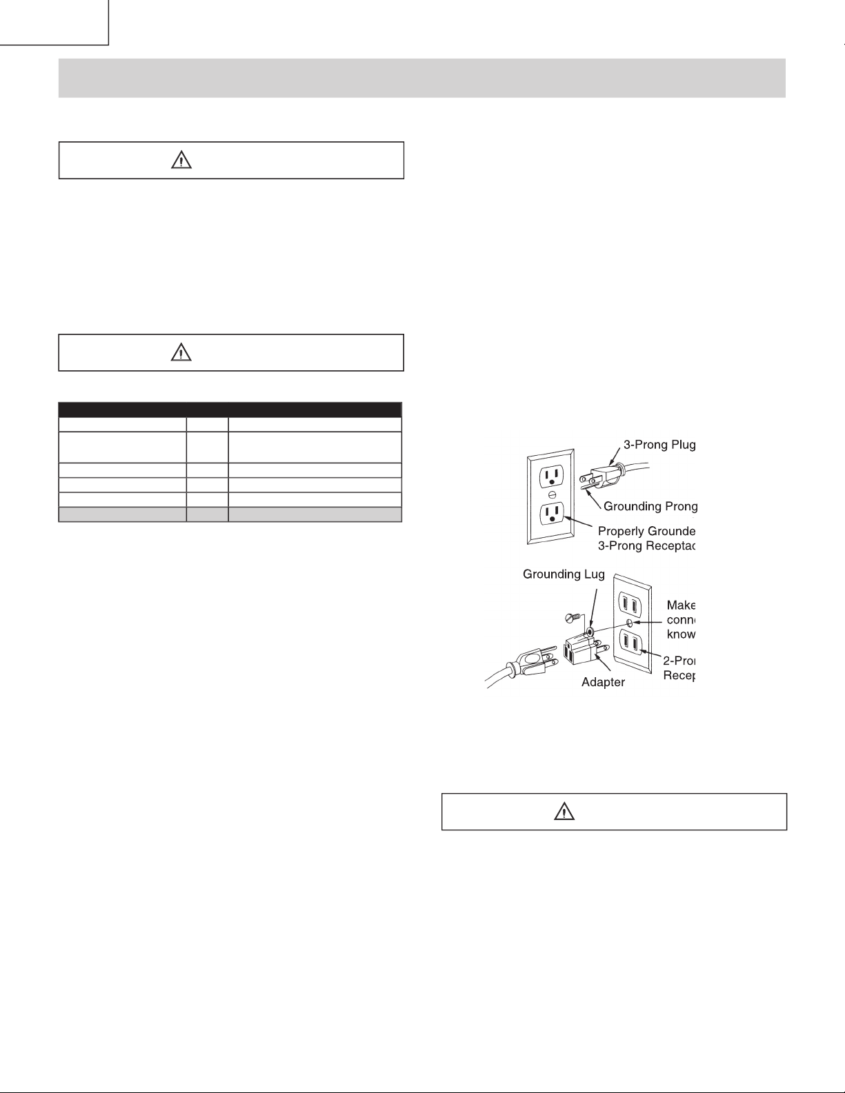
power source outlet
SAFETY
used for power tools MUST be
The 12 to 16 amp rating is correct for this tool. It
MINIMUM GAUGE FOR EXTENSION CORDS (AWG)
16 16 14
16 14 12
16 14 12
12
Page 7
–
7
–
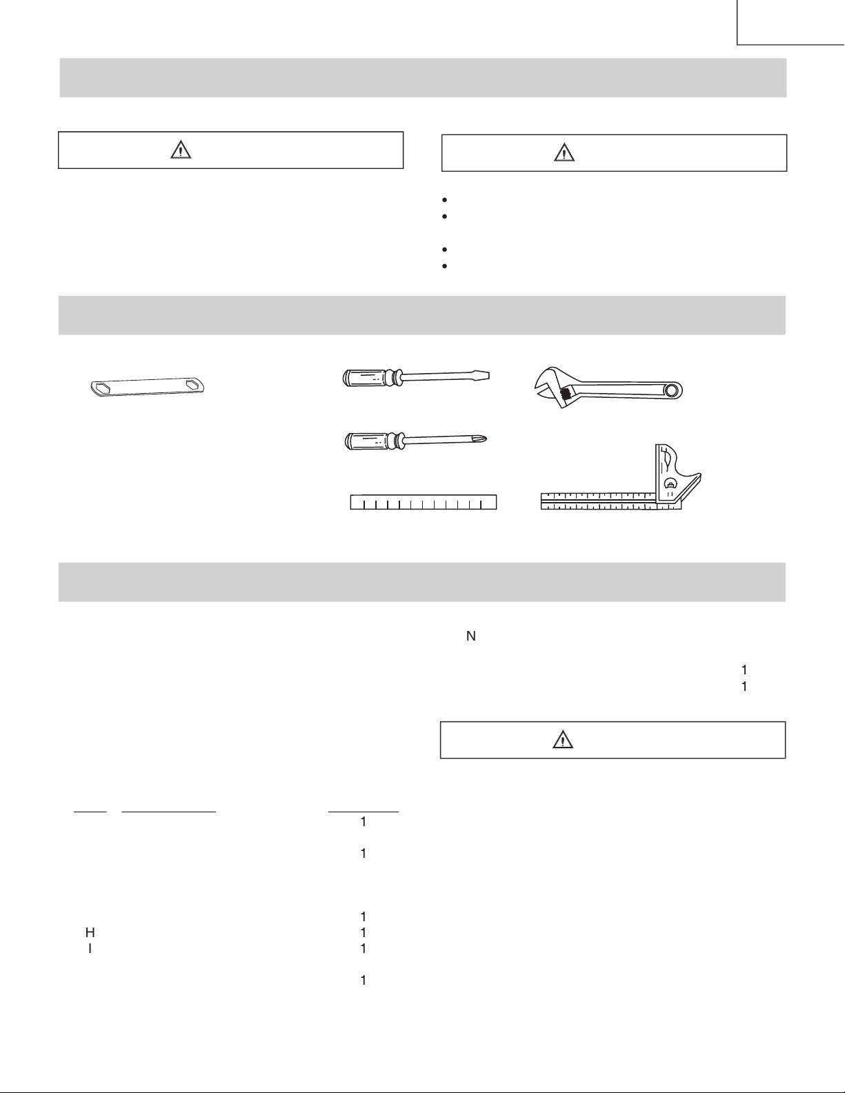
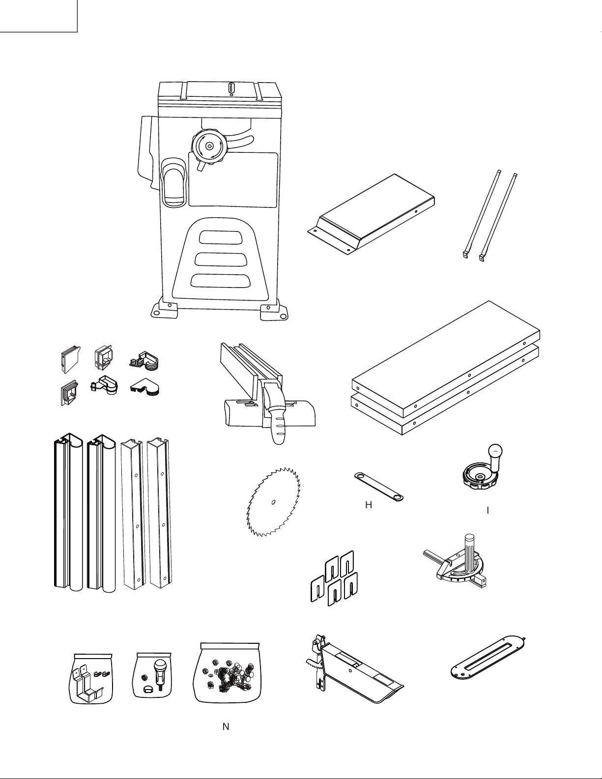
Supplied
Hex Wrench
CONTENTS
1 set
1 each
1 each
Page 8
–
8
–
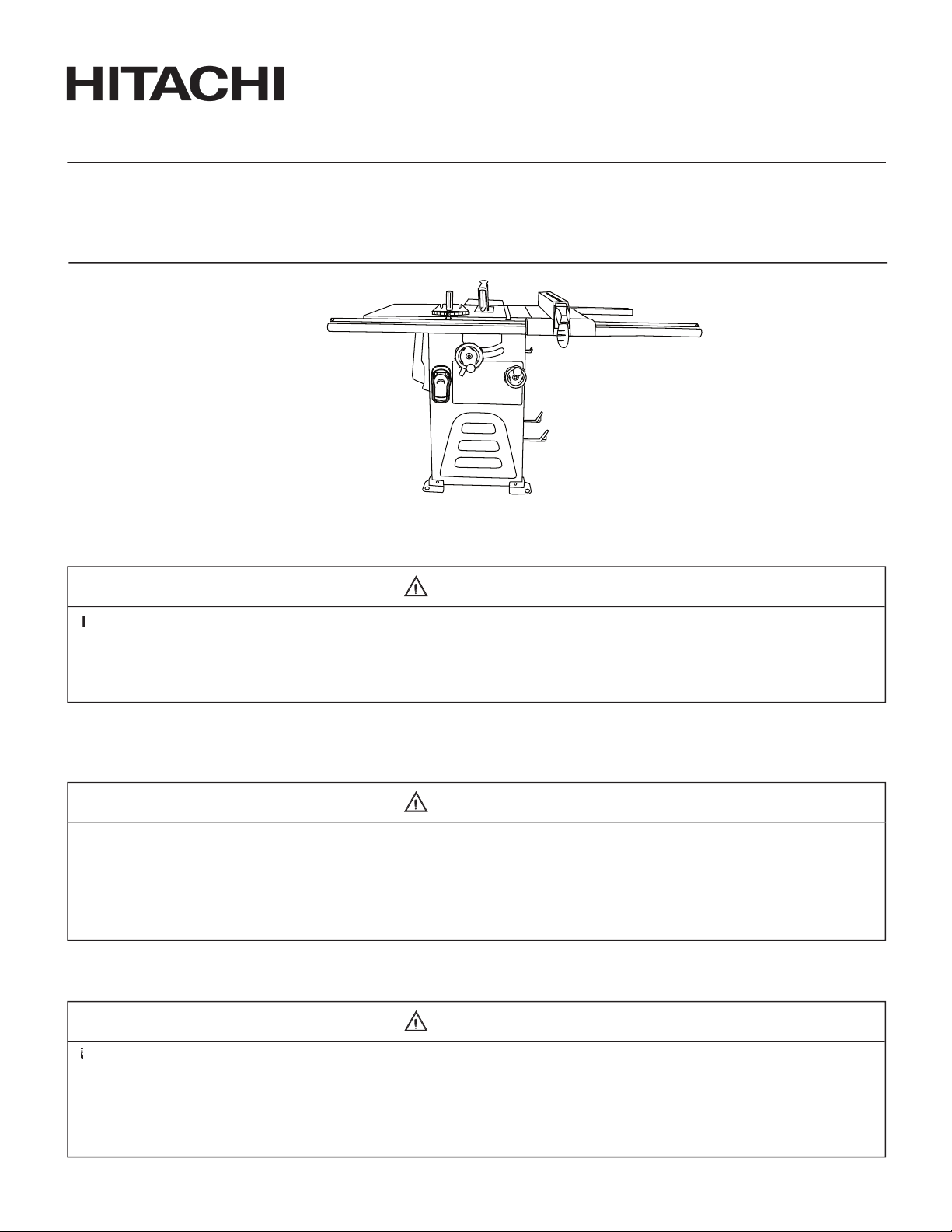
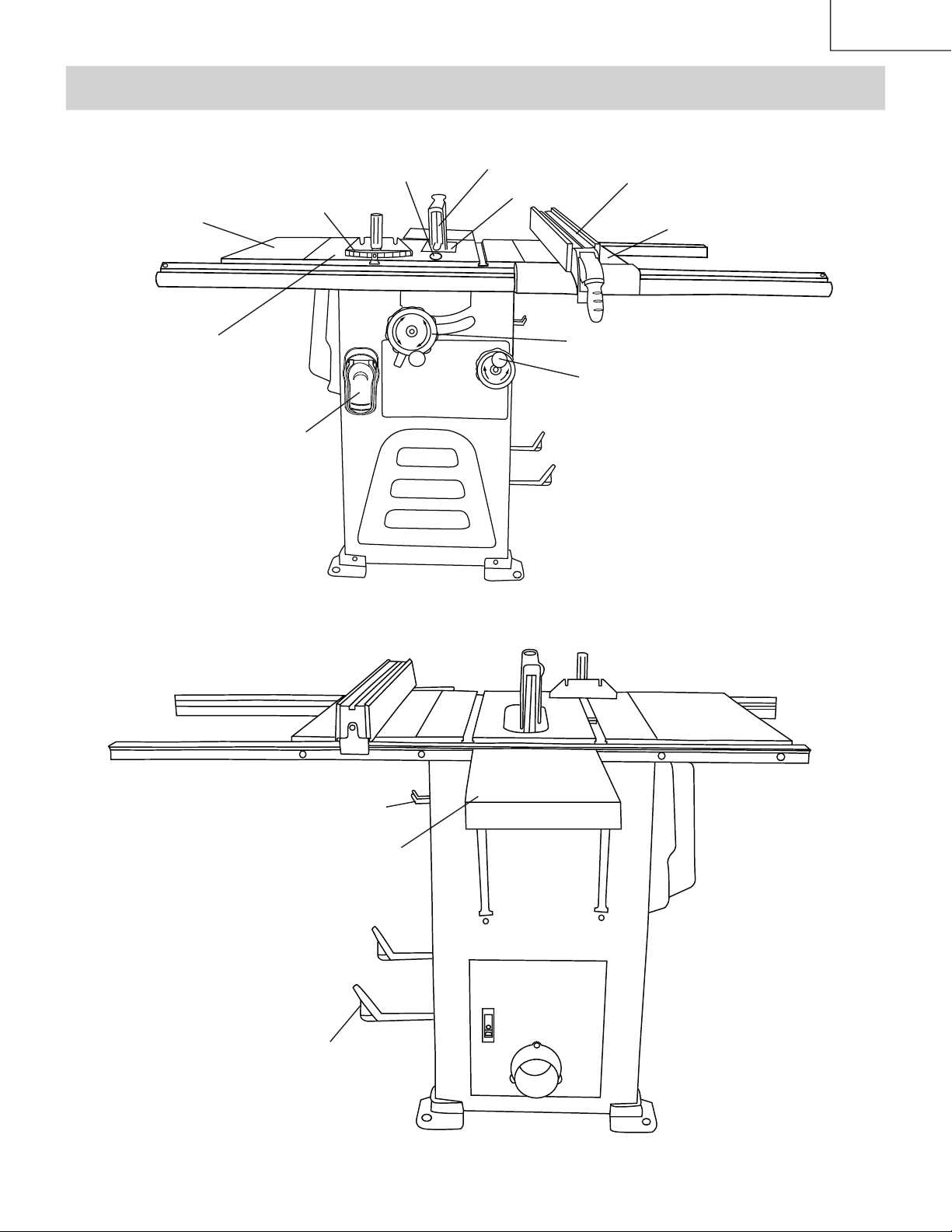
TABLE SAW
Page 9
–
9
–
Page 10

–
10
–
SAW TERMS
Prevents the workpiece
A simultaneous bevel and miter
Page 11

–
11
–
THE STYROFOAM FROM THE CABINET-
Page 12

–
12
–
Page 13

–
13
–
on the bevel scale.
and replace the table insert.
vertical position by
position and check the
a. Remove the blade guard by removing the wing
b. Loosen and remove the two bolts (3) from the
and 45
Page 14

–
14
–
vertical position by
machine.
Page 15

–
15
–
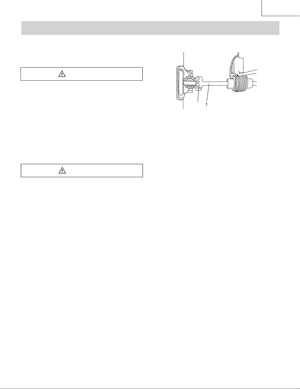
POSITIVE STOPS
and 45° to the table. Make adjustments
Stop (Fig. H, H-1)
A
B
3
4
5
6
1
2
Stop (Fig. I)
on the scale.
A
B
4
3
5
6
0
ı
5
ı
10
ı
Page 16

–
16
–
(FIG. M)
GAUGE ADJUSTMENT (FIG. N)
on the scale.
cut in a scrap piece of wood. Check
GAUGE OPERATION (FIG. N)
, 15
, 30
, 45
, 60
both right and left side.
, 45
, 60
both right and left side.
(FIG. K)
Page 17

–
17
–
1
2
5
6
7
1
12
13
20
21
22 24
4 1
Page 18

–
18
–
O
F
F
O
N
Page 19
–
19
–
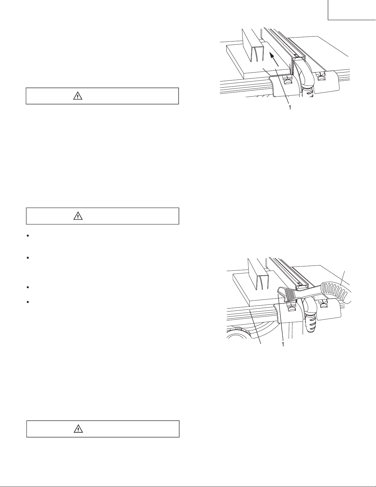
from the path of the blade.
by pushing forward on the section
3
Page 20

–
20
–
Do not allow familiarity or frequent use of your table
Keep both hands away from the blade and the path
Never attempt to pull the workpiece backwards
When tilting the blade to 45
Page 21

–
21
–
inju
at that time.
and tighten the blade bevel lock knob.
Cut the piece to shape and size shown:
4-3/4”
Page 22

–
22
–
Page 23
–
23
–
Certain cleaning chemicals can damage
Page 24

–
24
–
Service Center.
mechanisms.
Page 25
–
25
–
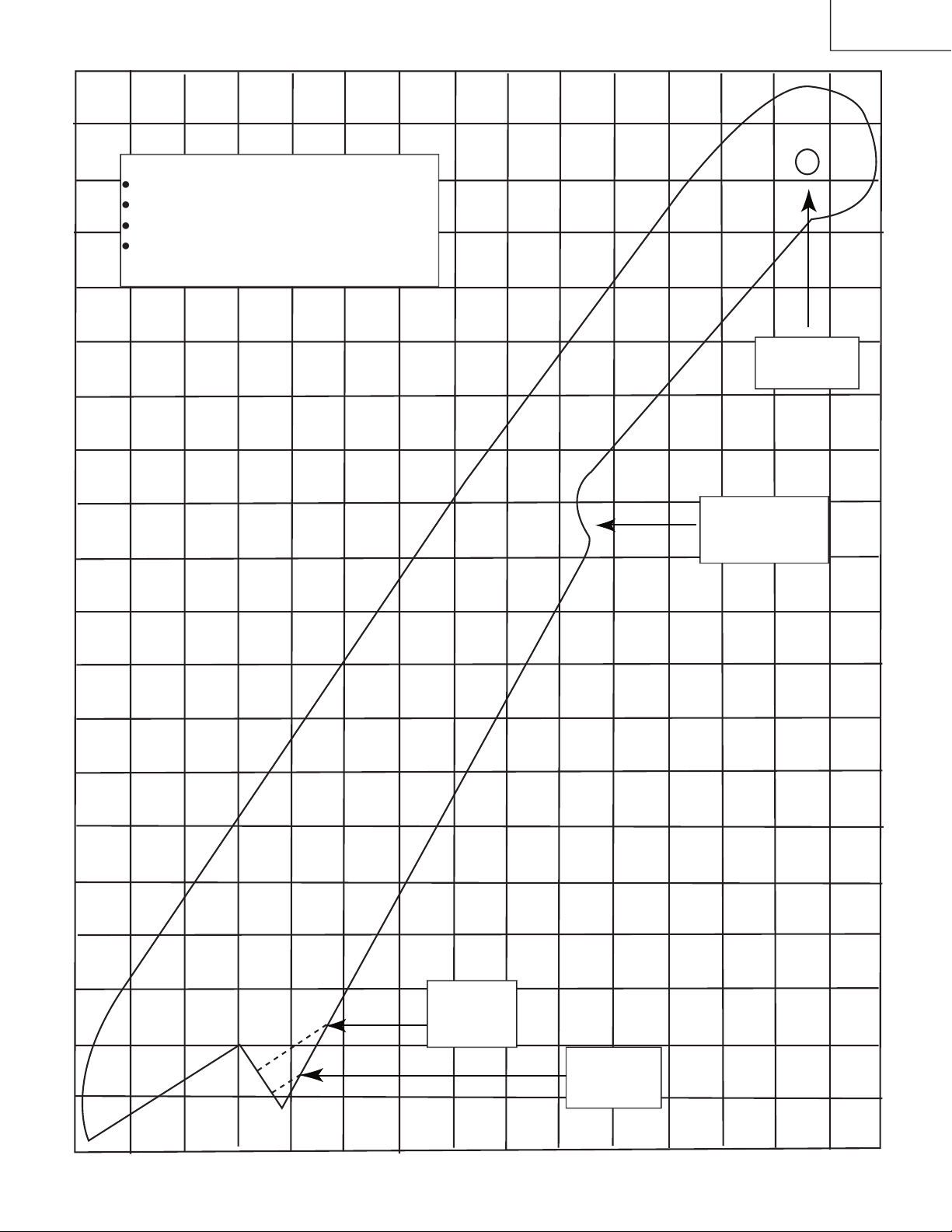
This is a full-size drawing (actual size)
Use good quality plywood or solid wood
Use 1/2 in. or 3/4 in. material
Push stick MUST be thinner than the width
Page 26

–
72
–
Size
Size
SPINDLE PULLEY
SET NUT
SIDE COVER (LEFT)
SIDE COVER (RIGHT)
SPECIAL BOLT
SCREW
T=0.2MM
SHAFT
SPRING PIN
T=3mm
SPRING PIN
SWITCH MOUNTING
SPLIT PIN
SWITCH BOX
SWITCH BOX COVER
STICKER LABEL
T=0.5MM
SLOTTED PAN HD. SCREW
TILTING SCALE
SQUARE NUT
SERRATED TOOTHED HEXAGON FLANGE NUT
SUPPORT ROD
STRAIN RELIEF
STRAIN RELIEF
SPRING PIN
SLEEVE
ASS’Y
SET PLATE
SCALE (RIGHT)
SCALE (LEFT)
SPONGE
SET PLATE
TORSION SPRING
T=3MM
Page 27

–
73
–
Page 28

–
74
–
Black
Black
120V
60HZ
Power
Rocker Switch
White
White
Blue
Black
Brown
(Terminal Block)
Black
Motor
White
White
Black
Black
Black
Black
(CIRCUIT BREAKER
SWITCH)
Black
(Rocker Switch)
240V
60HZ
Power
(Terminal Block)
White
White
Black
Blue
Black
Black
Motor
White
White
Black
Black
Black
Black
(CIRCUIT BREAKER
SWITCH)
Motor
Green
(GROUND)
(CIRCUIT BREAKER
SWITCH)
Black
White
White
Black
Black
Black
Black
Terminal Block
Rocker Switch
Blue
Black
Black
Brown
White
Power Cord
White
Black
White
Black
Green
(GROUND)
Motor
Green
(GROUND)
CIRCUIT BREAKER
SWITCH
Black
White
White
Black
Black
Black
Black
Terminal Block
Rocker Switch
Blue
Black
Black
White
Power Cord
White
Black
White
Black
Green
(GROUND)
120 V Wire Wirding
240 V Wire Wirding
Page 29

–
75
–
Issued by
Minato-ku, Tokyo 108-6020, Japan
Distributed by
 Loading...