

Page 1
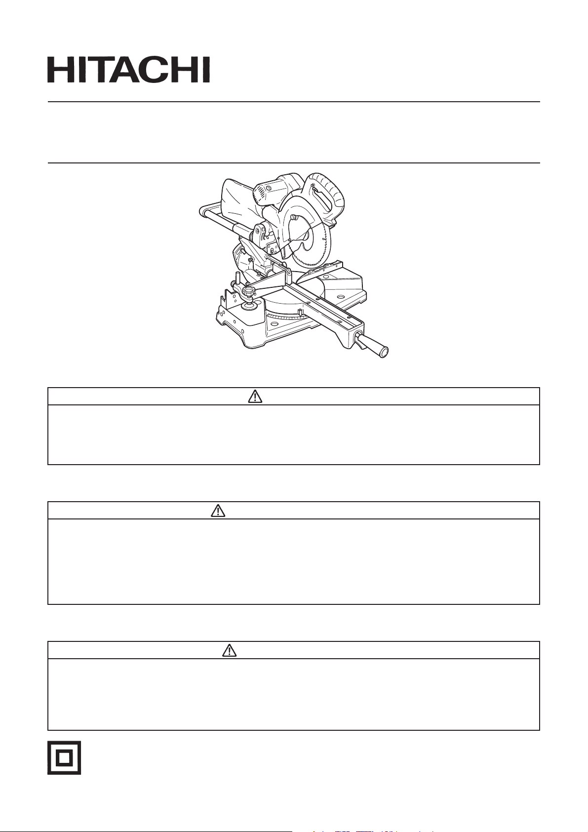
Model Slide Compound Saw
C 10FSH
Modèle Scie a coupe d’onglet radiale
Modelo Tronzadora radial abatible
C 10FSB
(Laser Marker Equipment)
(Equipement à marqueur laser)
(Equipo con marcador làser)
SAFETY INSTRUCTIONS AND INSTRUCTION MANUAL
WARNING
IMPROPER OR UNSAFE use of this power tool can result in death or serious bodily injury!
This manual contains important information about product safety. Please read and understand
this manual BEFORE operating the power tool. Please keep this manual available for other
users and owners before they use the power tool. This manual should be stored in safe place.
INSTRUCTIONS DE SECURITE ET MODE D’EMPLOI
AVERTISSEMENT
Une utilisation INCORRECTE OU DANGEREUSE de cet outil motorisé peut entraîner la mort ou de
sérieuses blessures corporelles!
Ce mode d’emploi contient d’importantes informations à propos de la sécurité de ce produit.
Prière de lire et de comprendre ce mode d’emploi AVANT d’utiliser l’outil motorisé. Garder ce
mode d’emploi à la disponibilité des autres utilisateurs et propriétaires avant qu’ils utilisent
l’outil motorisé. Ce mode d’emploi doit être conservé dans un en
droit sûr.
INSTRUCCIONES DE SEGURIDAD Y MANUAL DE INSTRUCCIONES
ADVERTENCIA
¡La utilización INAPROPIADA O PELIGROSA de esta herramienta eléctrica puede resultar en lesiones
de gravedad o la muerte!
Este manual contiene información importante sobre la seguridad del producto. Lea y comprenda este
manual ANTES de utilizar la herramienta eléctrica. Guarde este manual para que puedan leerlo otras
personas antes de utilizar la herramienta eléctrica. Este manual debe ser guardado en un lugar seguro.
DOUBLE INSULATION
DOUBLE ISOLATION
AISLAMIENTO DOBLE
Page 2

English
IMPORTANT SAFETY INFORMATION ..................... 3
MEANINGS OF SIGNAL WORDS ............................. 3
SAFETY .............................................................................. 3
IMPORTANT SAFETY INSTRUCTIONS FOR
USING ALL POWER TOOLS ................................... 3
REPLACEMENT PARTS .............................................. 6
USE PROPER EXTENSION CORD ............................. 7
DOUBLE INSULATION FOR SAFER OPERATION ... 7
OPERATION AND MAINTENANCE ............................... 8
NAME OF PARTS ........................................................ 8
SPECIFICATIONS ........................................................ 9
ACCESSORIES ........................................................... 10
CONTENTS
PAGE
PAGE
APPLICATIONS ......................................................... 10
PREPARATION BEFORE OPERATION .................... 11
BEFORE USING.......................................................... 12
BEFORE CUTTING ..................................................... 13
PRACTICAL APPLICATIONS ................................... 18
SAW BLADE MOUNTING AND
DISMOUNTING ..................................................... 26
OVERLOAD PROTECTIVE DEVICE FOR
POLY-V-BELT ......................................................... 27
MAINTENANCE AND INSPECTION ....................... 27
SERVICE AND REPAIRS ........................................... 29
PARTS LIST ................................................................ 88
Français
INFORMATIONS IMPORTANTES
DE SÉCURITÉ ......................................................... 30
SIGNIFICATION DES MOTS
D’AVERTISSEMENT ............................................. 30
SECURITE ........................................................................ 30
CONSIGNES DE SECURITE RELATIVES AUX
OUTILS ÉLECTRIQUES ......................................... 30
PIECES DE RECHANGE ............................................ 34
UTILISER LE CORDON DE
RALLONGE APPROPRIÉ ....................................... 34
DOUBLE ISOLATION POUR UN
FONCTIONNEMENT PLUS SUR .......................... 34
UTILISATION ET ENTRETIEN ...................................... 36
NOM DES PIÈCES ..................................................... 36
Español
INFORMACIÓN IMPORTANTE SOBRE
SEGURIDAD ........................................................... 59
SIGNIFICADO DE LAS PALABRAS DE
SEÑALIZACIÓN ..................................................... 59
SEGURIDAD .................................................................... 59
NORMAS DE SEGURIDAD PARA LAS
HERRAMIENTAS ELÉCTRICAS ........................... 59
PIEZAS DE REEMPLAZO .......................................... 63
UTILICE EL CABLE PROLONGADOR
ADECUADO ............................................................ 64
AISLAMIENTO DOBLE PARA OFRECER UNA
OPERACIÓN MÁS SEGURA ................................ 64
OPERACIÓN Y MANTENIMIENTO .............................. 65
NOMENCLATURA DE PARTES ............................... 65
ESPECIFICACIONES ................................................. 66
TABLE DES MATIERES
PAGE
PÁGINA
PAGE
SPÉCIFICATIONS ...................................................... 37
ACCESSOIRES ........................................................... 38
APPLICATIONS ......................................................... 38
PRÉPARATION AVANT L’UTILISATION ................ 39
AVANT L’UTILISATION ............................................ 40
AVANT LA COUPE..................................................... 41
APPLICATIONS PRATIQUES ................................... 46
INSTALLATION ET RETRAIT DE LA LAME ............ 55
DISPOSITIF DE PROTECTION
ANTI-SURCHARGE DE LA
POLY-COURROIE EN V ......................................... 56
ENTRETIEN ET INSPECTION .................................. 56
SERVICE APRÈS-VENTE ET RÉPARATIONS ......... 58
ÍNDICE
PÁGINA
ACCESORIOS ............................................................. 67
APLICACIONES ......................................................... 67
PREPARATIVOS PREVIOS A LA OPERACIÓN ...... 68
ANTES DE LA UTILIZACIÓN .................................... 69
ANTES DEL CORTE ................................................... 70
APLICACIONES PRÁCTICAS ................................... 75
MONTAJE Y DESMONTAJE DE LA
HOJA DE SIERRA .................................................. 84
DISPOSITIVO PROTECTOR CONTRA
SOBRECARGA PARA LA CORREA
EN V DE POLIVINILO ............................................ 85
MANTENIMIENTO E INSPECCIÓN ........................ 85
SERVICIO Y REPARACIONES .................................. 87
Page 3

English
IMPORTANT SAFETY INFORMATION
Read and understand all of the safety precautions, warnings and operating instructions in the Instruction
Manual before operating or maintaining this power tool.
Most accidents that result from power tool operation and maintenance are caused by the failure to observe
basic safety rules or precautions. An accident can often be avoided by recognizing a potentially hazardous
situation before it occurs, and by observing appropriate safety procedures.
Basic safety precautions are outlined in the “SAFETY” section of this Instruction Manual and in the sections
which contain the operation and maintenance instructions.
Hazards that must be avoided to prevent bodily injury or machine damage are identified by WARNINGS on
the power tool and in this Instruction Manual.
NEVER use this power tool in a manner that has not been specifically recommended by HITACHI.
MEANINGS OF SIGNAL WORDS
WARNING indicates a potentially hazardous situations which, if ignored, could result in death or serious
injury.
CAUTION indicates a potentially hazardous situations which, if not avoided, may result in minor or moderate
injury, or may cause machine damage.
NOTE emphasizes essential information.
SAFETY
IMPORTANT SAFETY INSTRUCTIONS FOR USING ALL POWER TOOLS
READ ALL OF THE WARNINGS AND OPERATING INSTRUCTIONS IN THIS MANUAL
BEFORE OPERATING OR MAINTAINING THIS TOOL:
WARNING: When using this electric tool, take all necessary precautions to minimize the risk of electric
shock or other personal injury.
In particular, always comply with the following safety rules:
1. ALWAYS KEEP GUARDS IN PLACE and in working order.
2. ALWAYS REMOVE ADJUSTING KEYS AND WRENCHES BEFORE STARTING TOOL.
Always confirm that all keys and adjusting wrenches have been removed from the tool before it is
turned on.
3. ALWAYS KEEP WORK AREA CLEAN. Avoid injuries by not cluttering the work areas and work
benches.
4. NEVER USE TOOL IN HAZARDOUS ENVIRONMENTS. Never use the power tool in damp or
wet places and never expose it to rain. Always keep the work area well lighted.
5. NEVER PERMIT CHILDREN OR OTHERS TO LOITER NEAR THE WORK AREA. Keep all
people (especially children) away from the work area. Always unplug unattended tools and keep the
work place tamper-proof by installing locks on the doors and on the master switches. Always remove
the lock-off button from the tool and store it in a secure place, when the tool is not in use.
6. NEVER FORCE THE TOOL. It will do the job better and more safely if it is operated at the rate for
which it was designed.
7. ALWAYS USE THE RIGHT TOOLS. Never force a tool or an attachment to do a job for which it
was not designed.
8. ALWAYS WEAR PROPER APPAREL WHEN WORKING WITH THE TOOL. Never wear loose
clothing, gloves, neckties, rings, bracelets or other jewelry which may get caught in the moving parts.
Always wear non-slip footwear, preferably with steel toes. Wear protective hair covering to contain
long hair.
3
Page 4

English
9. ALWAYS USE EYE PROTECTION WHEN WORKING WITH THE TOOL TO PREVENT
EYE INJURY.
made of safety glass. Also, use a face mask for additional safety and wear a dust mask if the cutting
operation produces dust.
Ordinary eyeglasses do not provide adequate protection because the lenses are not
10. ALWAYS SECURE THE WORKPIECE TO THE FENCE OR THE TABLE. Use clamps or a vise
to hold the workpiece in place. It is safer than using your hand and it frees both hands to operate the
tool.
11. NEVER OVERREACH. Always keep proper footing and balance when working with the tool.
12. ALWAYS MAINTAIN TOOLS WITH CARE. Always keep tools sharp and clean for the best and
safest performance. Always follow instructions for lubricating the tool and for changing accessories.
13. ALWAYS DISCONNECT THE TOOL before servicing and before changing blades or other
accessories.
14. NEVER RISK UNINTENTIONAL STARTING WHEN PLUGGING IN THE TOOL. Always
confirm that the switch is in the OFF position before inserting the power plug into the receptacle.
15. ALWAYS USE RECOMMENDED ACCESSORIES ONLY WHEN OPERATING THIS TOOL.
Consult this instruction manual for descriptions of recommended accessories. To avoid personal injuries,
use only recommended accessories in conjunction with this tool.
16. NEVER STAND ON THE TOOL. Prevent serious injury by not tipping the tool and by not risking
unintentional contact with the saw blade.
17. ALWAYS CHECK FOR DAMAGED PARTS BEFORE USING THE TOOL. Always check the
guard and all other components for damage before using the tool to assure that they will function
properly. Check all moving parts for proper alignment, freedom from binding and other conditions that
might affect proper operation. Always repair or replace any damaged guards or other damaged
components before using the tool.
18. ALWAYS CONFIRM THE ROTATION DIRECTION OF THE BLADE BEFORE USING THE
TOOL.
possible injury.
Always feed work into the tool against the rotation direction of the blade in order to prevent
19. NEVER LEAVE THE TOOL RUNNING WHILE UNATTENDED. TURN POWER OFF. Do not
leave tool until it comes to a complete stop. Always turn the power off when the tool is not in use.
Always unplug the power cord when the tool is not in use.
20. This tool was not designed to be used for mass-production applications and should not be used in
mass-production environments.
21. When servicing this tool, use only authorized replacement parts.
22. Apply 120 volts AC only to this tool. Applying the wrong voltage or applying DC power can cause the
POWER TOOL to operate improperly and cause serious personal injury or damage to the tool.
23. Never raise the saw blade from the workpiece until it has first come to a complete stop.
24. Always use outboard stands to provide support for long workpieces that overhang the table of the slide
compound saw.
25. Always return the carriage to the full rear position after each crosscut operation in order to reduce the
risk of injury.
26. POLARIZED PLUGS To reduce the risk of electric shock, this equipment has a polarized plug (one
blade is wider than the other). This plug will fit in a polarized outlet only one way. If the plug does not fit
fully in the outlet, reverse the plug. If it still does not fit, contact a qualified electrician to install the
proper outlet. Do not change the plug in any way.
Specific Safety Rules for Use of this Power Tool
WARNING: The following specific operating instructions must be observed when using this POWER
TOOL in order to avoid injury:
DO’s
ALWAYS OBSERVE THE FOLLOWING RULES TO ASSURE SAFE USE OF THIS TOOL:
Review this Manual and familiarize yourself with the safety rules and operating instructions for this
1.
POWER TOOL before attempting to use it.
2. Always confirm that the POWER TOOL is clean before using it.
4
Page 5

English
3. Always wear snug-fitting clothing, non-skid footwear (preferably with steel toes) and eye protection
when operating the POWER TOOL.
4. Always handle the POWER TOOL carefully. If the POWER TOOL falls or strikes against a hard object, it
might become deformed or cracked or sustain other damage.
5. Always cease operating the saw at once, if you notice any abnormality whatsoever.
6. Always confirm that all components are mounted properly and securely before using the tool.
7. When replacing the saw blade, always confirm that the rpm rating of the new blade is correct for use on
this tool.
8. Always shut off the power and wait for the saw blade to completely stop rotating before doing any
maintenance or adjustments.
9. During slide cutting, always push the saw blade away from the operator.
10. Always clamp or otherwise secure the workpiece to the fence; otherwise the workpiece might be thrust
form the table and cause bodily harm.
11. During miter or bevel cutting, always wait for the rotation of the blade to stop completely before lifting
the saw blade.
12. Always make a trial run first before attempting any new use of the saw.
13. Always handle the saw blade with care when dismounting and mounting it.
14. Always confirm that the workpiece is free of nails or other foreign objects before beginning a cut.
15. Always keep your hands out of the path of the saw blade.
16. Always confirm that the safety cover is in the proper place before using the saw.
17. Always confirm that the safety cover does not obstruct the sliding motion of the saw before attempting
slide cutting.
18. Inspect the tool power cords periodically.
19. Always confirm that the proper lengths and types of extension cords are being utilized, if necessary,
before starting the tool.
20. Always confirm that the motor air vents are fully open before using the tool.
21. Always wait until the motor has reached full speed before starting a cut.
22. Always keep the handles dry, clean and free of oil and grease. Hold the tool firmly when in use.
23. Always use outboard stands to provide support for long workpieces that overhang the table of the slide
compound saw.
24. Always operate the tool after ensuring the workpiece is fixed properly with a vise assembly.
25. The operating instructions provided with the tool shall direct the user to secure the tool to supporting
structure if, during normal operation, there is a tendency for the tool to tip over, slide, or walk on the
supporting surface.
DON’Ts
NEVER VIOLATE THE FOLLOWING RULES TO ASSURE SAFE USE OF THIS TOOL:
Never operate the POWER TOOL unless you fully understand the operating instructions contained in
1.
this Manual.
2. Never leave the POWER TOOL unattended without first unplugging the power cord.
3. Never operate the POWER TOOL when you are tired, after you have taken any medications, or have
consumed any alcoholic beverages.
4. Never use the POWER TOOL for applications not specified in the instruction manual.
5. Never operate the tool while wearing loose clothing, a necktie or jewelry, or while your hair is uncovered,
to protect against getting caught in the moving machinery.
6. Never reach around the saw blade.
7. Never touch any moving parts, including the blade, while the saw is in use.
8. Never remove any safety devices or blade guards; use of the tool without them would be hazardous.
5
Page 6

English
9. Never lock the safety cover; always confirm that it slides smoothly before using the tool.
10. Never damage the power cord of the tool.
11. Never attempt to move a plugged-in POWER TOOL while your finger is on the starting switch.
12. Never use the POWER TOOL if the starting switch does not turn on and off properly.
13. Never use the POWER TOOL if the plastic housing or the handle is cracked or deformed.
14. Never use the POWER TOOL near flammable liquids or gases because sparking can cause an explosion.
15. Never clean plastic components with solvents because the plastic may dissolve.
16. Never operate the saw unless all the blade guards are in place.
17. Never raise the saw blade from the workpiece until it has first come to a complete stop.
18. When slide cutting, never pull the handle toward the operator, since this could cause the saw blade to
kick up from the workpiece. Always push the handle away from the operator in a single, smooth motion.
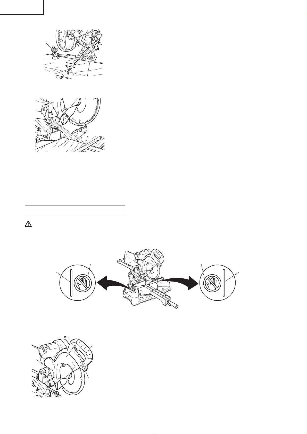
19. Never place your limbs inside of the line next to warning sign “ ” while the tool is being operated.
This may cause hazardous conditions.
20. Never use abrasive type blades on this saw.
21. Never expose to rain or use in damp locations.
22. Never cut ferrous metals or masonry.
WARNING
FOR YOUR OWN SAFETY READ THIS INSTRUCTION MANUAL BEFORE OPERATING THE
SLIDE COMPOUND SAW
Always wear eye protection when using the slide compound saw.
1.
2. Always keep hands out of the path of the saw blade.
3. Never operate the saw without the guards in place.
4. Never perform any freehand operation with the slide compound saw.
5. Never reach around the saw blade.
6. Always turn off tool and wait for saw blade to stop before moving workpiece or changing settings.
7. Always disconnect power before changing blade or servicing.
8. Saw blade diameter is 10" (255mm).
9. No load speed is 3800/min.
10. To reduce the risk of injury, return carriage to the full rear position after each crosscut operation.
REPLACEMENT PARTS
When servicing use only identical replacement parts.
Repairs should be conducted only by a Hitachi authorized service center.
6
Page 7

English
USE PROPER EXTENSION CORD
Make sure your extension cord is in good condition. When using an extension cord, be sure to use one
heavy enough to carry the current your product will draw. An undersized cord will cause a drop in line
voltage resulting in loss of power and overheating. Table shows the correct size to use depending on cord
length and nameplate ampere rating. If in doubt, use the next heavier gage. The smaller the gage number,
the heavier the cord.
MINIMUM GAGE FOR CORD SETS
Total Length of Cord in Feet (Meter)
0 – 25 26 – 50 51 – 100 101 – 150
(0 – 7.6) (7.9 – 15.2) (15.5 – 30.5) (30.8 – 45.7)
Ampere Rating AWG
More Not More
Than Than
0 – 6 18 16 16 14
6 – 10 18 16 14 12
10 – 12 16 16 14 12
12 – 16 14 12 Not Recommended
WARNING: Avoid electrical shock hazard. Never use this tool with a damaged or frayed electrical
cord or extension cord.
Inspect all electrical cords regularly. Never use in or near water or in any environment
where electric shock is possible.
DOUBLE INSULATION FOR SAFER OPERATION
To ensure safer operation of this power tool, HITACHI has adopted a double insulation design. “Double
insulation” means that two physically separated insulation systems have been used to insulate the electrically
conductive materials connected to the power supply from the outer frame handled by the operator. Therefore,
either the symbol “
Although this system has no external grounding, you must still follow the normal electrical safety precautions
given in this Instruction Manual, including not using the power tool in wet environments.
To keep the double insulation system effective, follow these precautions:
* Only HITACHI AUTHORIZED SERVICE CENTER should disassemble or assemble this power tool, and only
genuine HITACHI replacement parts should be installed.
* Clean the exterior of the power tool only with a soft cloth moistened with soapy water and dry thoroughly.
* Never use solvents, gasoline or thinners on plastic components; otherwise the plastic may dissolve.
” or the words and “Double insulation” appear on the power tool or on the nameplate.
SAVE THESE INSTRUCTIONS
AND
MAKE THEM AVAILABLE TO
OTHER USERS
AND
OWNERS OF THIS TOOL!
7
Page 8
English
OPERATION AND MAINTENANCE
NOTE: The information contained in this Instruction Manual is designed to assist you in the safe operation
and maintenance of the power tool. Some illustrations in this Instruction Manual may show details
or attachments that differ from those on your own power tool.
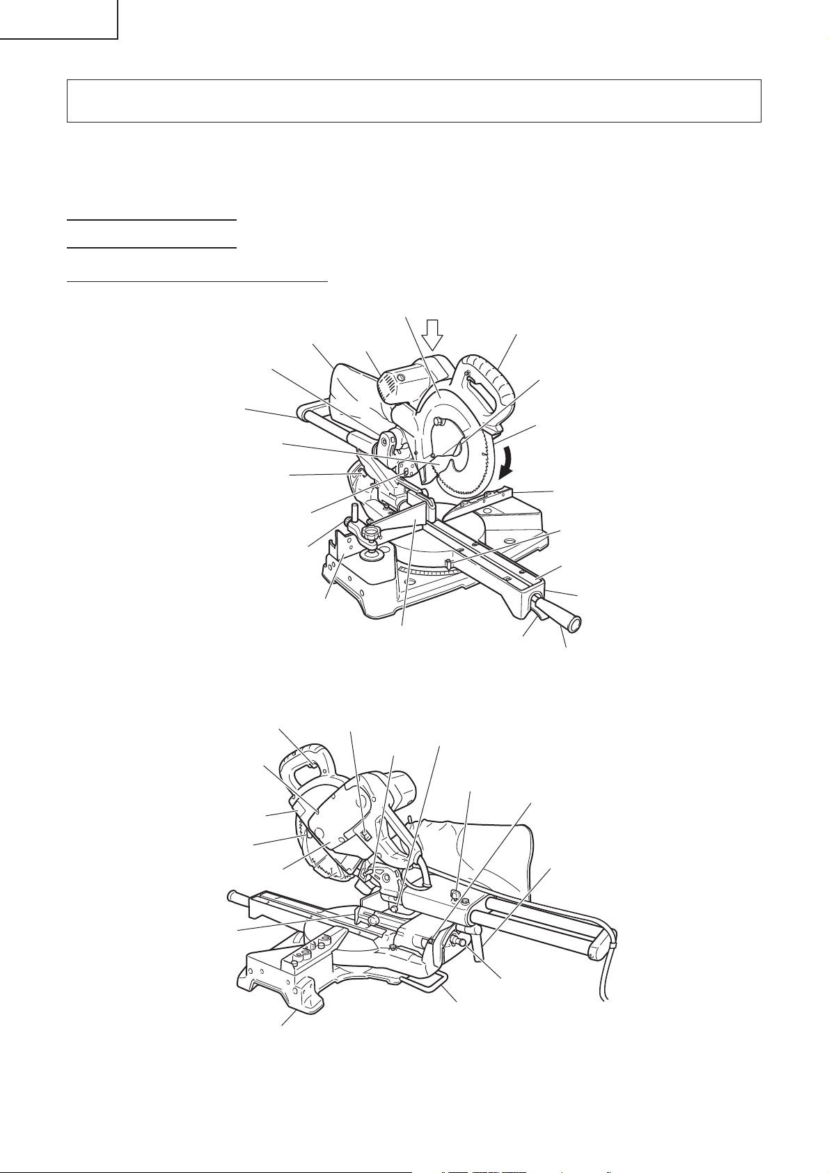
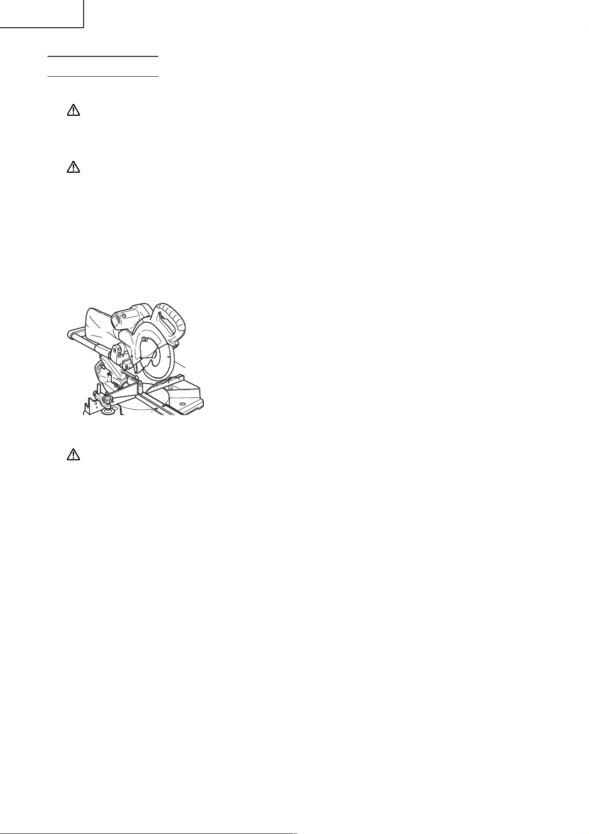
NAME OF PARTS
MODEL C10FSH/MODEL C10FSB
Hinge
Holder (A)
Saw Blade
Indicator
(For right bevel scale)
Leser Marker
(Only C10FSH)
Vise Assembly
Trigger Switch
5mm Screw
Nameplate
Dust Bag
Fence (B)
Gear Case
Moter
Switch
(for Laser marker)
(Only C10FSH)
Locking Pin
Motor Head
Sub Fence
Fig. 1
Adjuster (Only C10FSH)
(for Laser marker)
Handle
Spindle Cover
Safety Cover
Rotation
Direction
Fence (A)
Indicator
(For miter scale)
Table Insert
Turntable
Lever
Side Handle
Slide Securing Knob
Indicator
(for left bevel scale)
Spindle Lock
Belt Cover
Guard
Fixing Pin
Holder
Base
Clamp Lever
Fig. 2
8
Page 9

SPECIFICATIONS
Item Model C 10FSH / C 10FSB
Motor Type Series commutator motor
Power source Single-phase AC 60Hz
Voltage (Volts) 120
Full-load current (Amp) 12
Laser Marker Maximum output <1mW CLASS II Laser Product
(Only Model Wave length 400~700 nm
C10FSH) Laser medium Laser Diode
Applicable Outside Dia. 10" (255mm)
saw blade Hole Dia. 5/8" (15.9mm)
No load speed 3800/min
Max. Head Turntable Max. sawing dimension
sawing Miter 0 0 Max. Height 3-11/32" (85mm)
dimension
0 Left 45° Max. Height 3-11/32" (85mm)
or Max. Width 8-19/32" (218mm)
Right 45° or
0 Right 57° Max. Height 3-11/32" (85mm)
Bevel Left 45° 0 Max. Height 2-3/16" (55mm)
Rigth 45° 0 Max. Height 1-3/16" (30mm)
Compound Left 45° Left 45° Max. Height 2-3/16" (55mm)
or Max. Width 8-19/32" (218mm)
Right 45° or
Right 45° Left 31° Max. Height 1-3/16" (30mm)
Right 45° Right 45° Max. Height 1-3/16" (30mm)
Miter sawing range Left 0° – 45° Right 0° – 57°
Bevel sawing range Left 0° – 45° Right 0° – 45°
Compound sawing range Left (Bevel) 0° – 45°, Left and Right (Miter) 0° – 45°
Right (Bevel) 0° – 45°, Left (Miter) 0° – 31°, Right (Miter) 0° – 45°
Net weight 43lbs. (19.5kg)
Cord 2 Conductor type cable 6ft. (1.8m)
Max. Width 12-9/32" (312mm)
or
* Max. Height 3-9/16" (90mm)
Max. Width 11" (280mm)
With aux. board 19/32" (15mm)
* Max. Height 3-9/16" (90mm)
Max. Width 7-1/2" (190mm)
With aux. board 19/32" (15mm)
Max. Width 6-1/2" (165mm)
or
* Max. Height 3-9/16" (90mm)
Max. Width 5-25/32" (147mm)
With aux. board 13/32" (10mm)
Max. Width 12" (305mm)
or
* Max. Height 2-3/8" (60mm)
Max. Width 11" (280mm)
With aux. board 19/32" (15mm)
Max. Width 12" (305mm)
or
* Max. Height 1-3/8" (35mm)
Max. Width 11" (280mm)
With aux. board 19/32" (15mm)
* Max. Height 2-3/8" (60mm)
Max. Width 7-1/2" (190mm)
With aux. board 19/32" (15mm)
Max. Width 10-7/32" (260mm)
or
* Max. Height 1-3/8" (35mm)
Max. Width 9-19/32" (230mm)
With aux. board 19/32" (15mm)
Max. Width 8-19/32" (218mm)
or
* Max. Height 1-3/8" (35mm)
Max. Width 7-1/2" (190mm)
With aux. board 19/32" (15mm)
English
9
Page 10
English
When cutting the workpiece which has the dimension of “*” there might be some possibility of the lower
end of the circular saw to touch with the workpiece, even if the motor head is located at the lower limit
position. Pay attention when cutting the workpiece. For further details, refer to “PRACTICAL APPLICATIONS”
on page 18. Mount the auxilliary board on the fence surface (Refer ( ) the thickness of auxiliary board).
Refer to "5. Cutting large workpieces" on page 20 (Fig. 29).
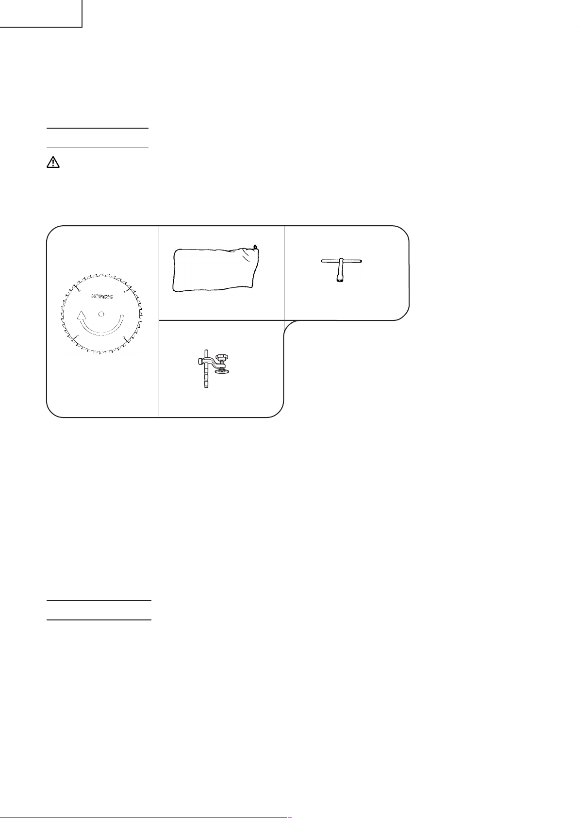
ACCESSORIES
WARNING: Accessories for this power tool are mentioned in this Instruction Manual.
The use of any other attachment or accessory can be dangerous and could cause injury
or mechanical damage.
STANDARD ACCESSORIES
blade (1 piece)
2 Dust bag (1 piece)1 10" (255mm) TCT Saw
For how to use, refer to
page 26.
3 Vise Assembly w/knob bolt
(1 piece)
(No. of teeth 40
Code No. 310878A)
For how to use, refer to
page 19.
Fig. 3
4 10mm BOX wrench
(1 piece)
OPTIONAL ACCESSORIES...sold separately
1 Extension Holder and Stopper (Code No. 321553)
2 Saw blade 10”(255mm) TCT Saw blade (Total teeth:72) (Code No. 725206)
3 Sub Fence (A) (Code No. 321387)
4 Crown molding Vise Ass’y (Code No. 321434) (Include Crown molding Stopper (L))
5 Crown molding Stopper (L) (Code No. 321374)
6 Crown molding Stopper (R) (Code No. 321373)
NOTE: Accessories are subject to change without any obligation on the part of the HITACHI.
APPLICATIONS
Wood and aluminum sash.
10
Page 11
PREPARATION BEFORE OPERATION
Make the following preparations before operating the power tool:
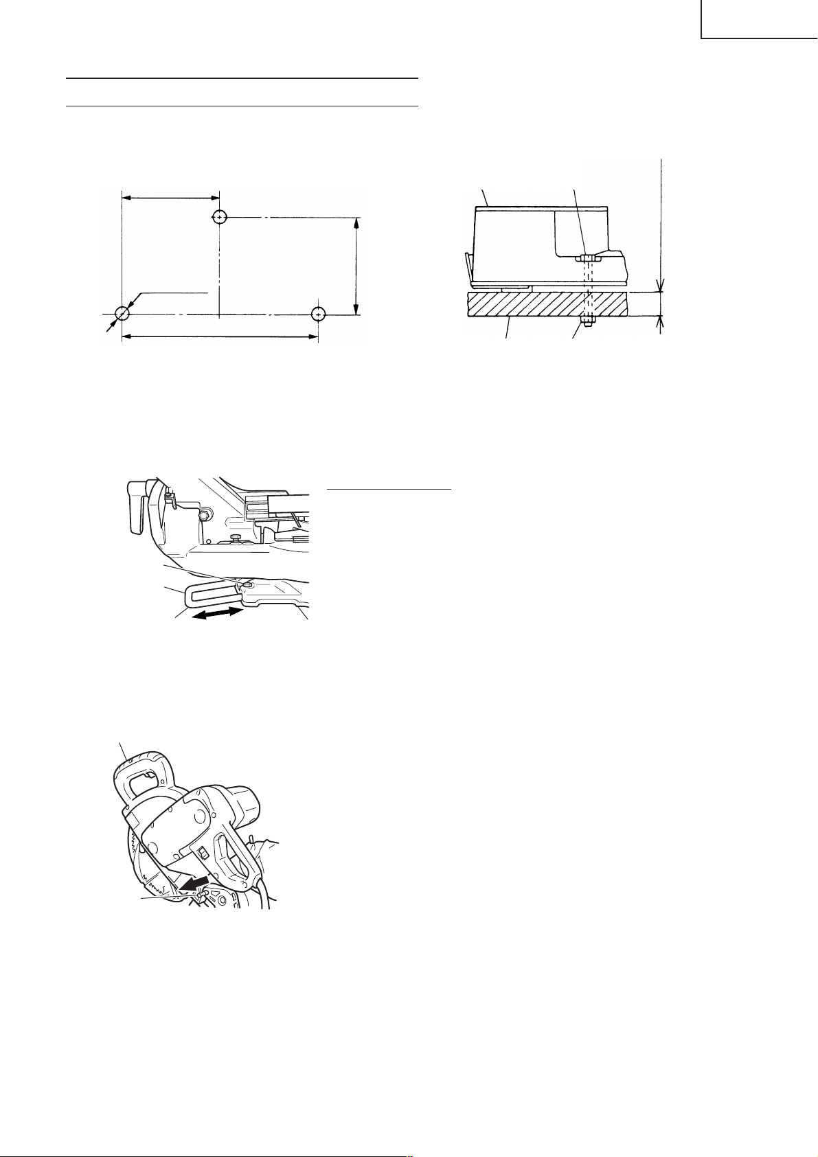
1. Installation
English
5-29/32"(150mm)
11/32" (9mm)
3 Holes
10-13/32" (264mm)
11-13/16" (300mm)
Work Bench
Fig. 4
5/16" (8mm) BoltBase
5/16" (8mm) Nut
Attach the power tool to a level, horizontal work bench in accordance with Fig. 4.
Select 5/16" (8mm) diameter bolts suitable in length for the thickness of the work bench.
Bolt length should be at least 1-9/16" (40mm) plus the thickness of the work bench.
For example, use 2-9/16" (65mm) or larger bolts for a 1" (25mm) thick work bench.
The holder attached to the rear of the base helps stabilize the power tool.
Holder adjustment:
Loosen the 6mm bolt with the supplied 10mm box wrench.
Adjust the holder until its bottom surface contacts the work bench
surface.
After adjustment, firmly tighten the 6mm bolt.
6mm Bolt
Holder
1" (25mm) thick bench
Adjust the holder
until its bottom
surface contacts the
work bench surface.
Move
Fig. 5
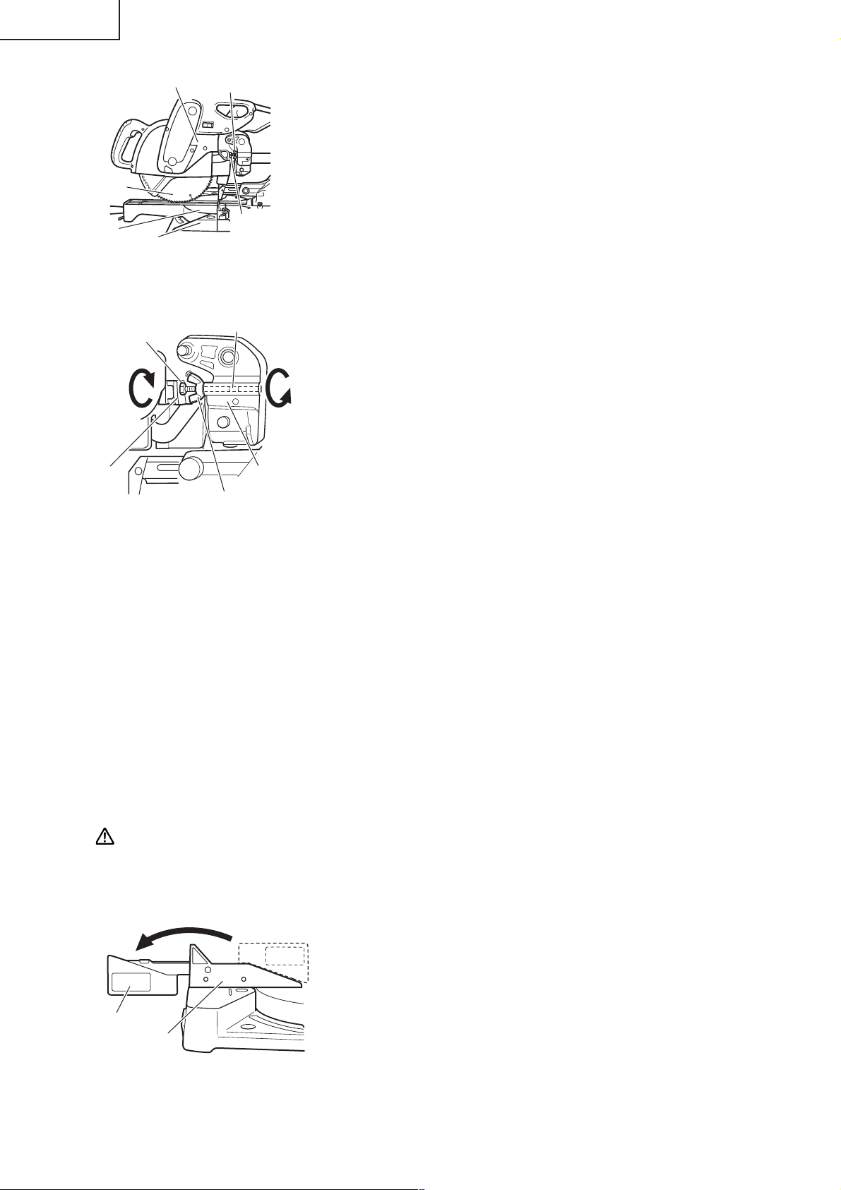
2. Releasing the locking pin
Handle
When the power tool is prepared for shipping, its main parts are
secured by a locking pin.
Move the handle slightly so that the locking pin can be disengaged.
NOTE: Lowering the handle slightly will enable you to disengage
the locking pin more easily and safely.
The lock position of the locking pin is for carrying and
storage only.
Pull
Locking Pin
Fig. 6
3. Installing the dust bag, holder, stopper and vises
(The holder and stopper are optional accessories.)
Attach the dust bag and vise assembly as indicated in Fig. 1 and Fig. 2.
11
Page 12
English
BEFORE USING
1. Make sure the power source is appropriate for the tool.
WARNING: Never connect the power tool unless the available AC power source is of the same
voltage as that specified on the nameplate of the tool.
Never connect this power tool to a DC power source.
2. Make sure the trigger switch is turned OFF.
WARNING: If the power cord is connected to the power source with the trigger switch turned
ON the power tool will start suddenly and can cause a serious accident.
3. Check the saw blade for visible defects.
Confirm that the saw blade is free of cracks or other visible damage.
4. Confirm that the saw blade is attached securely to the power tool.
Using the supplied 10mm box wrench, tighten the bolt on the saw blade spindle to secure the saw
blade.
For details, see Fig. 51-a, Fig. 51-b and Fig. 51-c in the section on “SAW BLADE MOUNTING AND
DISMOUNTING”.
5. Check the safety cover for proper operation.
Safety cover is designed to protect the operator from coming into
contact with the saw blade during operation of the tool.
Always check that the safety cover moves smoothly and covers
the saw blade properly.
Safety Cover
Fig. 7
WARNING: NEVER OPERATE THE POWER TOOL if the safety cover does not function smoothly.
6. Confirm the position of the spindle lock before using the tool.
After installing the saw blade, confirm that the spindle lock has been returned to the retract position
before using the power tool (see Fig. 2).
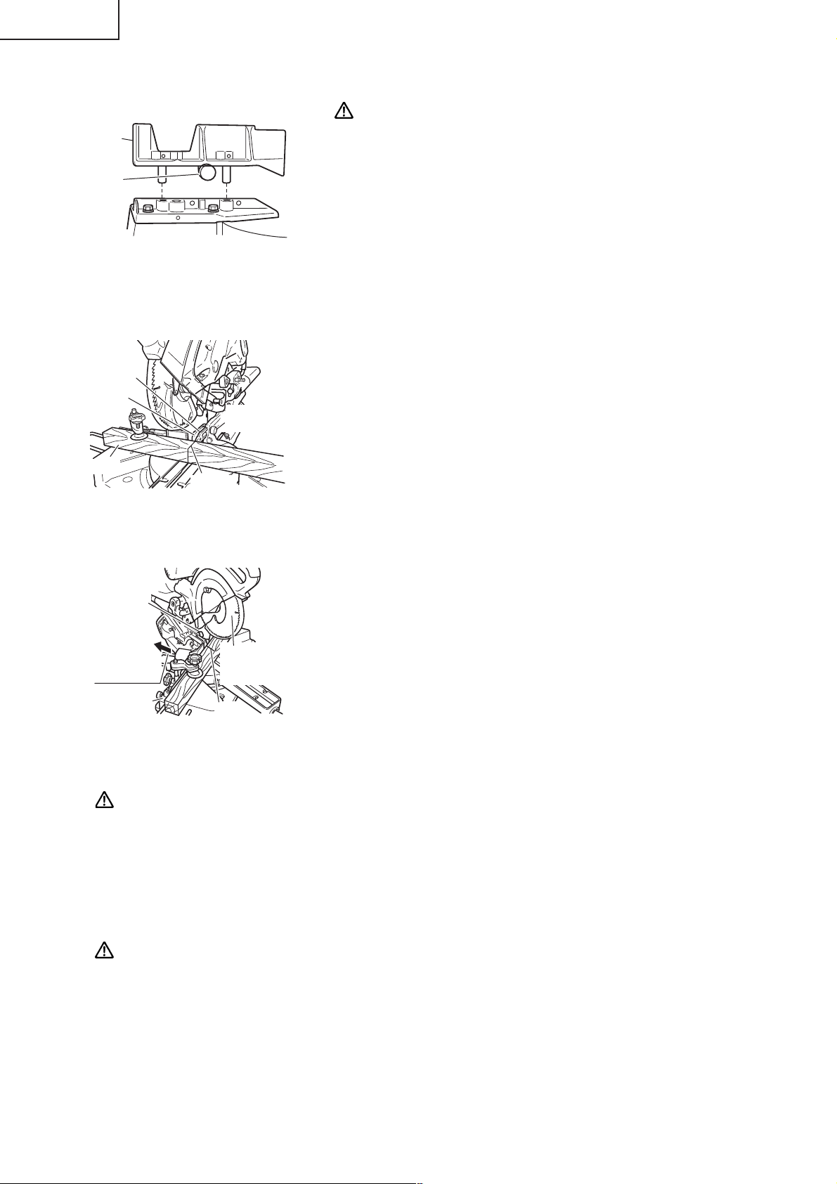
7. Check the lower limit position of the Saw Blade.
Although it was adjusted before shipment, carefully check the height of the saw blade. Confirm that the
saw blade can be lowered 13/32" to 7/16" (10mm to 11mm) below the table insert. For details, see the
section on “Checking the saw blade lower limit position”.
8. Check the Power Receptacle.
To prevent overheating, accidental stopping or intermittent operation, confirm that the power cord
plug fits properly in the electrical receptacle and does not fall out after it is inserted. Repair or replace
the receptacle if it is faulty.
9. Confirm the tool’s power cord is not damaged.
Repair or replace the power cord if an inspection indicates that it is damaged
AFTER CONNECTING THE POWER PLUG TO AN APPROPRIATE AC POWER SOURCE,
CHECK THE OPERATION OF THE TOOL AS FOLLOWS:
10. Trial Run
After confirming that no one is standing behind, the power tool start and confirm that no operating
abnormalities exist before attempting a cutting operation.
11. Inspect the rotating stability of the saw blade.
For precise cutting, rotate the saw blade and check for deflection to confirm that the blade is not noticeably
unstable; otherwise vibrations might occur and cause an accident.
12
Page 13
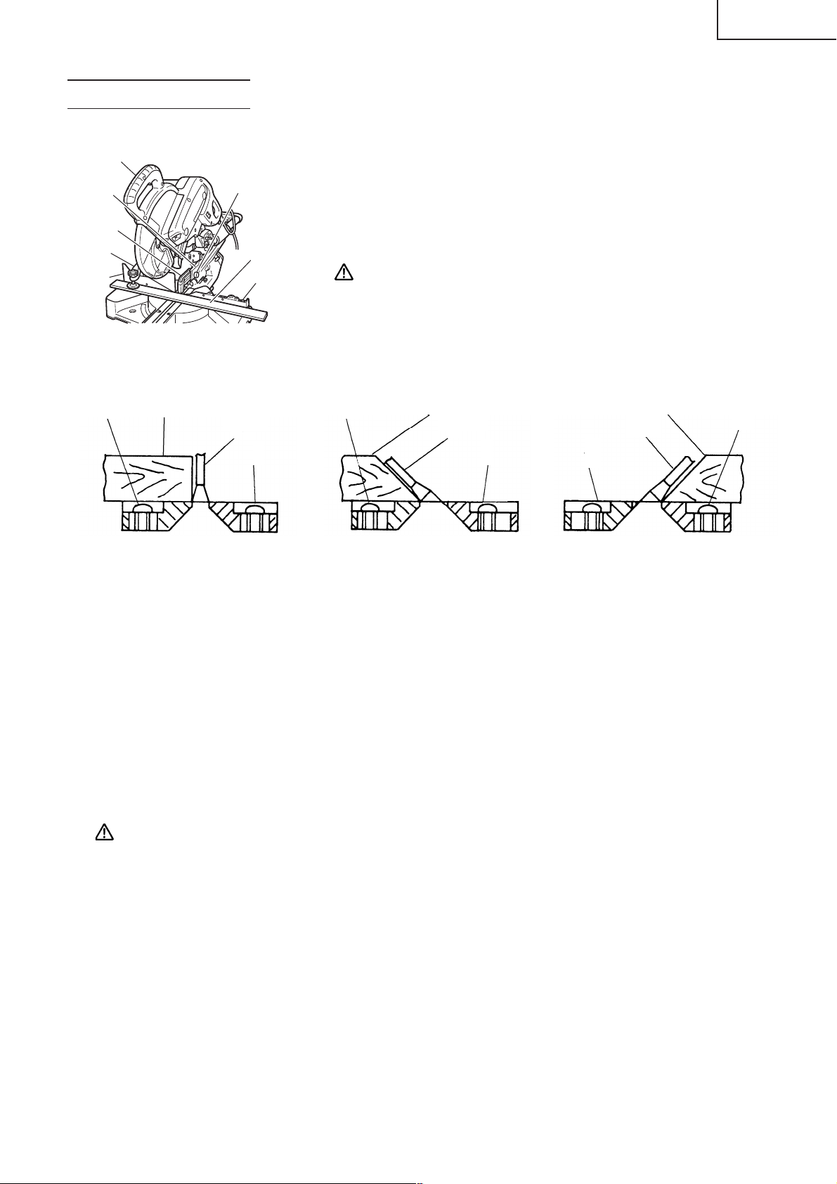
BEFORE CUTTING
1. Cutting a groove on the guard
Handle
Holder (A)
Guard
Vise
Assembly
Fence (B)
Fig. 8
2. Positioning the table insert
6mm Knob Bolt
Workpiece
Fence (A)
English
Holder (A) has a guard (see Fig. 8) into which a groove must be cut.
Loosen the 6mm knob bolt to retract the guard slightly. After placing
a suitable wooden piece to sit on the fence and the table surfaces,
fix it with the vise assembly.
After the switch has been turned on and the saw blade has reached
maximum speed, slowly lower the handle to cut a groove on the
guard (C).
CAUTION: Do not cut the groove too quickly; otherwise the
guard might become damaged.
6mm
Machine
Screw
Workpiece
Saw Blade
Table insert
[Right angle cutting] [Left bevel angle cutting] [Right bevel angle cutting]
Fig. 9-a Fig. 9-b Fig. 9-c
6mm
Machine
Screw
Workpiece
Saw Blade
Table insert
Workpiece
Saw Blade
Table insert
Table inserts are installed on the turntable. When shipping the tool from the factory, the table inserts
are so fixed that the saw blade does not contact them. The burr of the bottom surface of the workpiece
is remarkably reduced, if the table insert is fixed so that the gap between the side surface of the table
insert and the saw blade will be minimum. Before using the tool, eliminate this gap in accordance with
the following procedure.
(1) Right angle cutting
Loosen the three 6mm machine screws, then secure the left side table insert and temporarily tighten
the 6mm machine screws of both ends. Then fix a workpiece (about 7-7/8" (200mm) wide) with the
vise assembly and cut it off. After aligning the cutting surface with the edge of the table insert,
securely tighten the 6mm machine screws of both ends. Remove the workpiece and securely tighten
the 6mm center machine screw. Adjust the right hand table insert in the same way.
(2) Left and right bevel angle cutting
Adjust the table insert in the manner shown in Fig. 9-b and Fig. 9-c following the same procedure for
right angle cutting.
CAUTION: After adjusting the table insert for right angle cutting, the table insert will be cut to
some extent if it is used for bevel angle cutting.
When bevel cutting operation is required, adjust the table insert for bevel angle cutting.
6mm
Machine
Screw
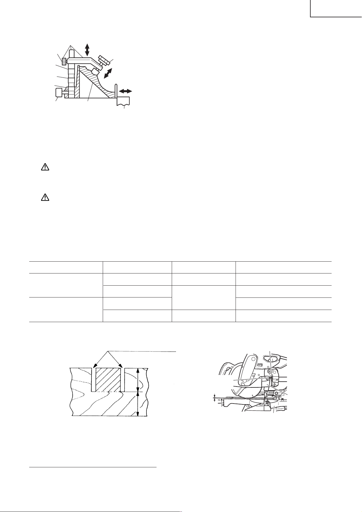
3. Checking the saw blade lower limit position
Check that the saw blade can be lowered 13/32" to 7/16" (10mm to 11mm) below the table insert as
shown in Fig. 10-a.
When you replace a saw blade with a new one, adjust the lower limit position so that the saw blade will
not cut the turntable or complete cutting cannot be done.
To adjust the lower limit position of the saw blade, follow the procedures (1) to (4) indicated below. (Fig.
10-b)
Furthermore, when changing the position of a 8mm depth adjustment bolt that serves as a lower limit
position stopper of the saw blade, it becomes necessary to shift the position of a 8mm hexagon socket
set screw that is in the screw hole for the 8mm depth adjustment bolt that serves as the stopper.
13
Page 14
English
Saw Blade
Turntable
Adjustment Bolt
Loosen
Gear Case
Gear Case
Base
8mm Depth
8mm Wing Nut
8mm Depth
Adjustment
Bolt
Fig. 10-a
8mm Hexagon Socket
Set Screw
(1) Loosen the 8mm wing nut.
(2) Insert your 6mm hexagon bar wrench from behind of the tool
and turn the 8mm hexagon socket set screw to the left
(counterclockwise) as viewed from behind of the tool.
(3) Turn the 8mm depth adjustment bolt, change the height where
the bolt head and the gear case contacts, and adjust the lower
limit position of the saw blade. One turn of the 8mm depth
adjustment bolt changes the lower limit position of the saw
blade by about 5/16"(8mm), and this information can be used
as a rough guide.
(4) Turn the 8mm hexagon socket set screw to the right (clockwise)
as viewed from behind of the tool, and let it softly contact the
tip of the 8mm depth adjustment bolt.
Turn
Hinge
8mm Wing Nut
Fig. 10-b
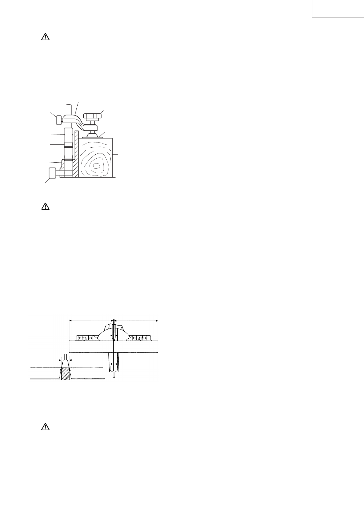
4. Lower limit position of saw blade when cutting a large workpiece
NOTE:
To adjust the lower limit position of the saw blade, follow the procedures (1) to (3) shown in Fig. 10-a.
(1) Loosen the 8mm wing nut so that the 8mm depth adjustment bolt can be turned by hand.
(2) Lower the motor head, and thrun the 8mm depth adjustment bolt by hand and make adjustments
(3) After adjustment, turn the 8mm wing nut until it contacts the Hinge (see Fig. 10-b), and fully tighten
When cutting a workpiece exceeding 3-11/32" (85mm) in height in right-angle cutting or 2-3/
16"(55mm) in left bevel angle cutting or 1-3/16" (30mm) in right bevel angle cutting, adjust
the lower limit position so that the base of the motor head (see Fig. 10-a) will not come in
contact with the workpiece.
so that there can be a clearance of 3/32" to 1/8" (2mm to 3mm) between the lower limit position of
the motor head and the top of the workpiece at the saw blade's lower limit position (where the head
of the 8mm depth adjustment bolt contacts the gear case.
it.
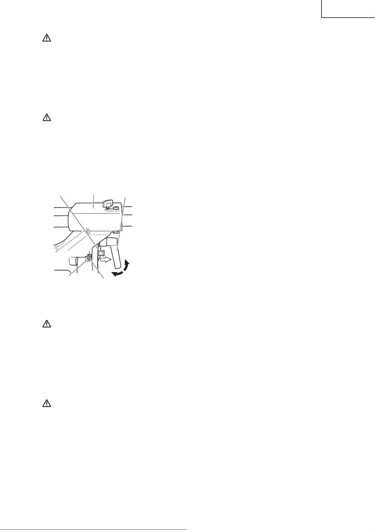
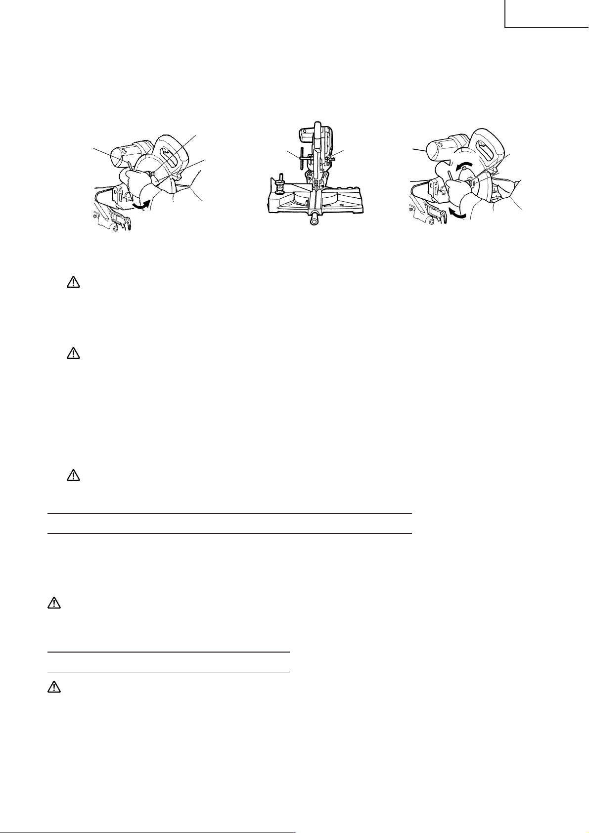
5. Confirmation for use of sub fence
WARNING: In the case of left bevel cutting, turn the sub fence counterclockwise. Unless it is
turned counterclockwise, the main body or saw blade may contact the sub fence,
resulting in an injury.
Left bevel angle cutting
Right bevel angle cutting
Direct angle cutting
Turn
This power tool is Equipped with a sub fence.
In the case of direct angle cutting and right bevel angle cutting, use
the sub fence. Then, you can realize stable cutting of the material
with a wide back face.
In the case of left bevel cutting, raise the sub fence up as illustrated
in Fig. 11 and then turn it counterclockwise.
Sub Fence
14
Fence (B)
Fig. 11
Page 15
6. Oblique angle
Before the power tool is shipped from the factory, it is adjusted for 0°, right angle, left 45° bevel cutting
angle and right 45° bevel cutting angle with the 8mm bolt (A), 8mm bolt (B) and the 8mm bolt (C).
When changing the adjustment, change the height of the 8mm bolt (A), 8mm bolt (B) or the 8mm bolt
(C) by turning them.
When changing the bevel angle to the right 45°, pull the fixing pin on the direction shown in Fig. 12-a
and incline the motor head to the right.
When adjusting the motor head to 0°, always return the fixing pin to its initial position as shown in Fig.
12-b.
Indicator (For right bevl scale)
8mm Bolt (A) (Stopper for 0°)
English
Fixing Pin
Pull
8mm Bolt (C)
(Stopper for left 45°
bevel angle)
Indicator
(For left bevel
scale)
Fig. 12-a Fig. 12-b
7. Securing the workpiece
WARNING: Always clamp or vise to secure the workpiece to the fence; otherwise the workpiece
might be thrust from the table and cause bodily harm.
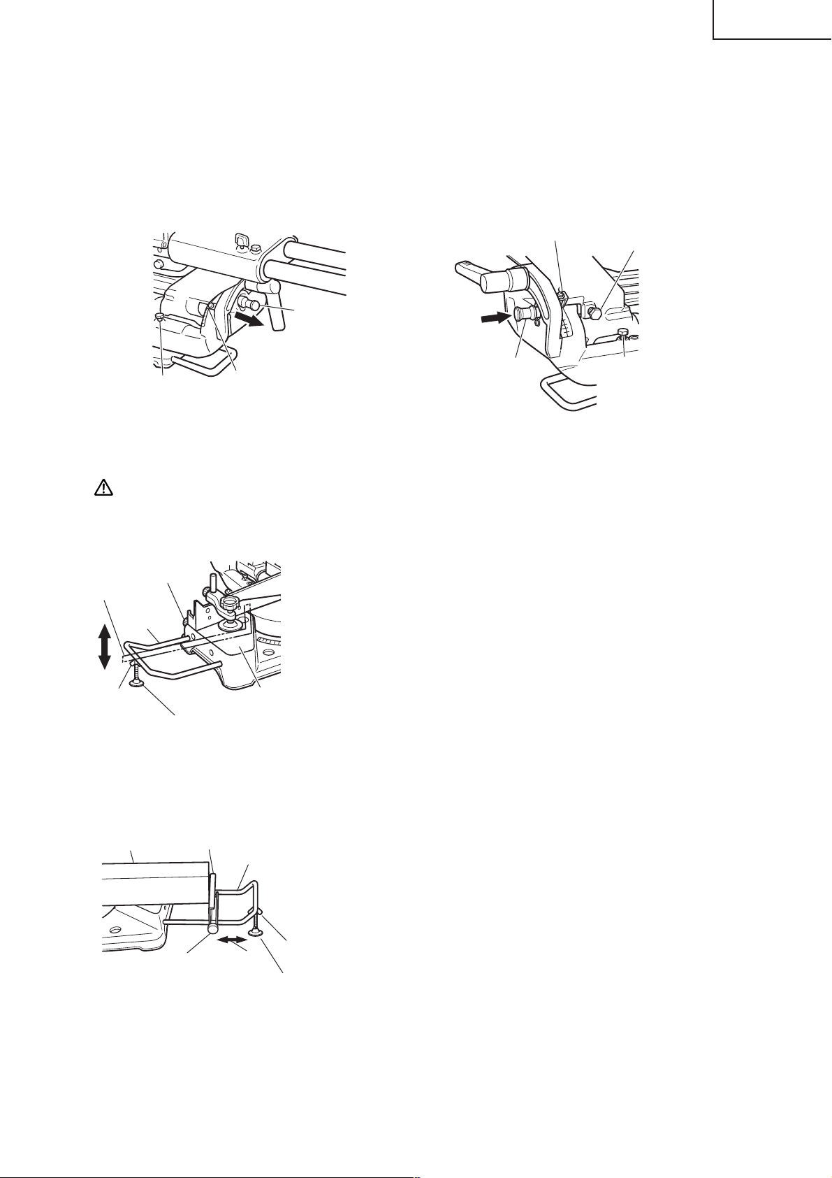
8. Installing the holders ... (Optional accessory)
The holders help keep longer workpieces stable and in place during
6mm Knob Bolt
(Optional accessory)
Steel
Square
6mm Wing Nut
(Optional
accessory)
Holder
(Optional
accessory)
Base Surface
Height Adjustment Bolt 6mm
(Optional accessory)
the cutting operation.
(1) As indicated in Fig. 13, use a steel square for aligning the upper
edge of the holders with the base surface.
Loosen the 6mm wing nut. Turn a height adjustment bolt 6mm,
and adjust the height of the holder.
(2) After adjustment, firmly tighten the wing nut and fasten the
holder with the 6mm knob bolt (optional accessory). If the length
of Height Adjustment Bolt 6mm is insufficient, spread a thin
plate beneath. Make sure the end of Height Adjustment Bolt
6mm does not protrude from the holder.
Return
Fixing Pin
8mm Bolt (B) (Stopper for
right 45° bevel angle)
Fig. 13
9. Stopper for precision cutting ... (Stopper and holder are optional accessory)
The stopper facilitates continuous precision cutting in lengths of
Workpiece
Stopper
(Optional accessory)
6mm Knob Bolt
(Optional accessory)
Fig. 14
Holder
(Optional
accessory)
6mm Wing Nut (Optional accessory)
Move
Height Adjustment Bolt 6mm (Optional accessory)
11" to 17-3/4" (280mm to 450mm).
To install the stopper, attach it to the holder with the 6mm knob
bolt as shown in Fig. 14.
15
Page 16
English
10. Confirmation for use of sub fence (A)…(Optional accessory)
WARNING: In the case of right bevel cutting, remove the sub
Sub Fence
(A)
6mm Knob
Bolt
In the case of direct angle cutting and angle cutting, use the sub
fence (A). The sub fence (A) can be installed on the right side of the
guide fence. Insert the rods of the sub fence (A) into the holes in
the guide fence. Tighten the 6mm knob bolt which come with the
sub fence (A) to secure the sub fence (A). Then, you can realize
stable cutting of the material with a wide back face.
Fig. 15
fence (A). Supposing it is not able to remove it,
It will contact the blade or some part of the tool,
causing in serious injury to operator.
11. Using an ink line
(1) Right angle cutting
Saw Blade
Groove
Guard
6mm
Knob Bolt
Loosen the 6mm knob bolt and contact the tip of the guard
with the workpiece.
Aligning the ink line on the workpiece with the groove of the
guard, the workpiece is cut on the ink line (Fig. 16).
Workpiece
Marking
(pre-marked)
Fig. 16
(2) Miter cutting and compound cutting
6mm Knob Bolt
(Miter cutting + bevel cutting)
Upon lowering the motor section, the safety cover is raised and
the saw blade appears.
Align the ink line with the saw blade (Fig. 17).
Move the
Guard
Backward
Fence (B)
Fig. 17
Safety
Cover
Marking
(pre-marekd)
CAUTION: In some arrangements when the turntable is rotated, the guard projects from the
fence surface. Loosen the 6mm knob bolt and push the guard to the retracted position.
Never lift the safety cover while the saw blade is rotating. When cutting at an angle
of 35° to the right or more, please slide the guard to the rear.
The guard and sub-fence will not only make contact and adversely affect cutting
accuracy, this could also result in damage to the guard.
12. Position adjustment of laser line (Only Model C10FSH)
WARNING: *Make sure before plugging the power plug into the receptacle that the main body
and the laser marker are turned off.
* Exercise utmost caution in handling a switch trigger for the position adjustment of
the laser line, as the power plug is plugged into the receptacle during operation.
If the switch trigger is pulled inadvertently, the saw blade can rotate and result in
unexpected accidents.
* Do not remove the laser marker to be used for other purposes.
16
Page 17

CAUTION:
Fig. 18
Fig. 19
* Laser radiation- Do not stare into beam.
* Laser radiation on work table. Do not stare into beam.
If your eye is exposed directly to the laser beam, it can be hurt.
* Do not dismantle it.
* Do not give strong impact to the laser marker (main body of tool); otherwise, the
position of a laser line can go out of order, resulting in the damage of the laser
marker as well as a shortened service life.
* Keep the laser marker lit only during a cutting operation. Prolonged lighting of the
laser marker can result in a shortened service life.
* Use of controls or adjustments or performance of procedures other than those
specified herein may result in hazardous radiation exposure.
NOTE: * Perform cutting by overlapping the ink line with the laser line.
* When the ink line and the laser line are overlapped, the strength and weakness of light will
change, resulting in a stable cutting operation because you can easily discern the conformity
of lines. This ensures the minimum cutting errors.
* In outdoor or near-the-window operations, it may become difficult to observe the laser line
due to the sunlight. Under such circumstances, move to a place that is not directly under the
sunlight and engage in the operation.
* Do not tug on the cord behind the motor head or hook your finger, wood and the like around
it; otherwise, the cord may come off and the laser marker may not be lit up.
Ink lining can be easily made on this tool to the laser marker. A
Switch
Laser line
switch lights up the laser marker. (Fig. 20)
Depending upon your cutting choice, the laser line can be aligned
with the left side of the cutting width (saw blade) or the ink line on
the right side.
The laser line is adjusted to the width of the saw blade at the time
of factory shipment. Adjust the positions of the saw blade and the
laser line taking the following steps to suit the use of your choice.
English
Workpiece
Marking
(pre-marked)
Fig. 20
Fig. 21
Saw Blade
Cutting Width
(1) Light up the laser marker and make a groove of about 3/16"
(5mm) deep on the workpiece that is about 25/32" (20mm) in
height and 5-29/32"(150mm) in width. Hold the grooved
workpiece by vise as it is and do not move it. For grooving
work, refer to "11.Groove cutting procedures" on page 25.
17
Page 18
English
Vise Assembly
(2) Then, turn the adjuster and shift the laser line. (If you turn the
adjuster clockwise, the laser line will shift to the right and if
you turn it counterclockwise, the laser line will shift to the left.)
When you work with the ink line aligned with the left side of
Laser Line
Move
Groove
Fig. 22
Turn
Adjuster
the saw blade, align the laser line with the left end of the groove.
(Fig. 22) When you align it with the right side of the saw blade,
align the laser line with the right side of the groove.
(3) After adjusting the position of the laser line, draw a right-angle
ink line on the workpiece and align the ink line with the laser
line. When aligning the ink line, slide the workpiece little by
little and secure it by vise at a position where the laser line
overlaps with the ink line. Work on the grooving again and check
Laser Line
the position of the laser line. If you wish to change the laser
line's position, make adjustments again following the steps from
(1) to (3).
Marking
(pre-marked)
Fig. 23
NOTE: Check and make sure on a periodic basis if the position of the laser line is in order. As regards
the checking method, draw a right-angle ink line on the workpiece with the height of about
25/32" (20mm) and the width of 5-29/32"(150mm), and check that the laser line is in line with
the ink line [The deviation between the ink line and the laser line should be less than the ink
line width (0.5mm)]. (Fig. 23)
PRACTICAL APPLICATIONS
WARNING: *To avoid personal injury, never remove or place a workpiece on the table while the tool
is being operated.
* Never place your limbs inside of the line next to warning sign while the tool is being
operated. This may cause hazardous conditions (see Fig. 24).
Warning Sign
Line
Line
1. Switch operation
Lock-off Button
Hole
Warning Sign
Handle
Trigger
Switch
Fig. 24
The trigger switch lock-off button is designed to prevent inadvertent
operation of the power tool. To operate the power tool, it is
necessary to first fully insert the lock-off button into the hole on
the handle as shown in Fig. 25.
The trigger switch will not operate unless the lock-off button has
been pushed in.
When the trigger switch is released, the power goes off and the
lock-off button automatically returns to its initial position, locking
the trigger switch.
18
Fig. 25
Page 19
WARNING: Always remove the lock-off button from the handle when the power tool is not in
use. This will ensure that the power tool cannot be turned on accidentally or by
someone (especially a child) who is not qualified to use the power tool. If the lock-off
button is left in the handle, serious personal injury can result. Since the lock-off button
fits rather tightly, it may be necessary to turn it to the left and right during mounting
and removing.
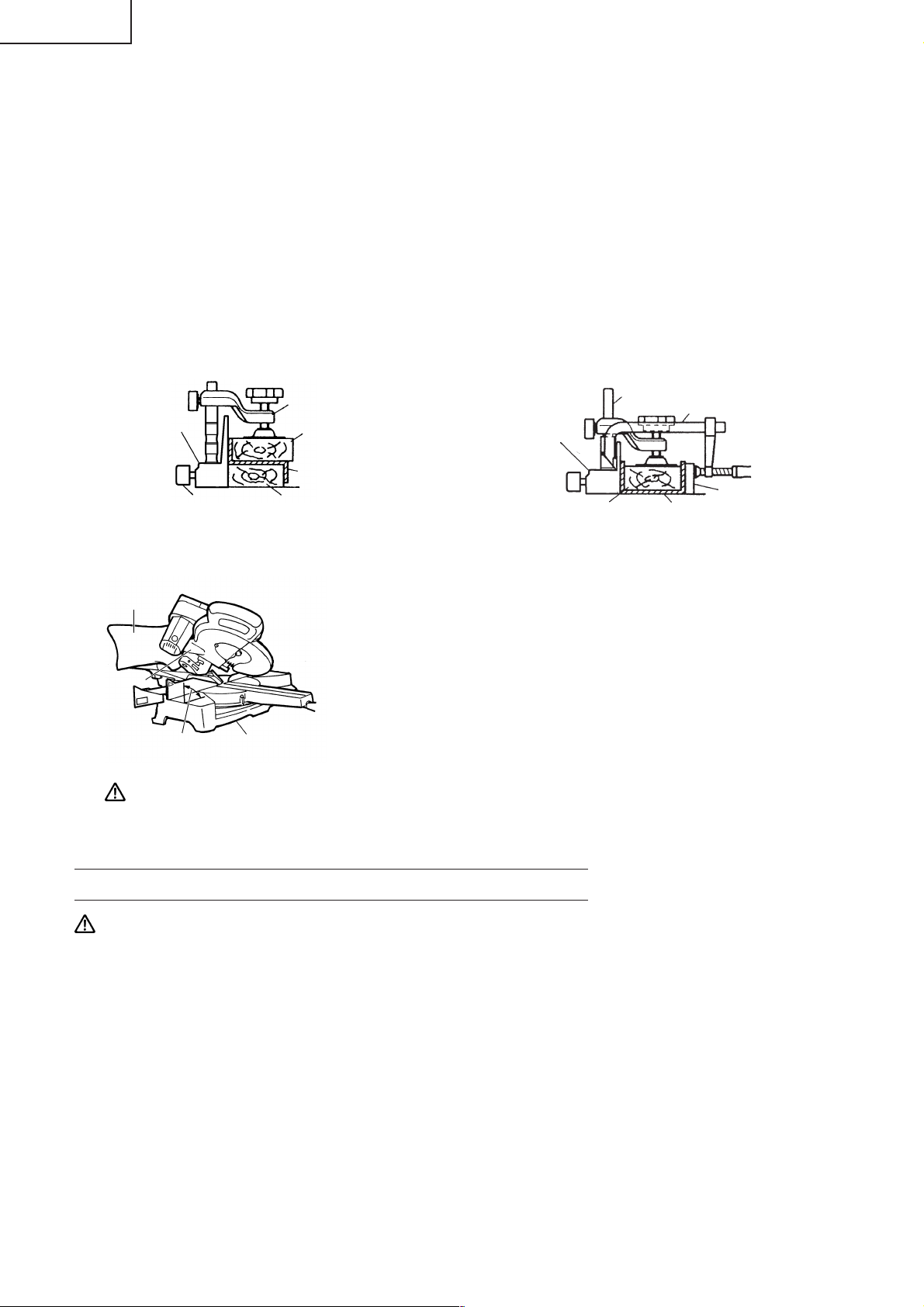
2. Using the Vise Assembly (Standard accessory)
The vise assembly can be mounted on either the left fence (Fence
(B)) or the right fence (Fence (A)), and can be raised or lowered
according to the height of the workpiece.
To raise or lower the vise assembly, first loosen the 6mm knob
bolt. As shown in Fig. 26, the vise shaft has three locking grooves
into which the tip of the 6mm wing bolt is designed to fit in order
to lock the screw holder in the desired position.
To ensure that the tip of the 6mm wing bolt is properly aligned
with the desired locking groove on the vise shaft, simply align the
upper surface of the fence to either of three v-grooves on the vise
shaft surface or to the lower surface of the screw holder.
Therefore, the vise assembly can be attached in either of three
positions to ensure proper height adjustment.
After adjusting the height, firmly tighten the 6mm wing bolt; then
turn the upper knob, as necessary, to securely attach the workpiece
in position.
6mm
Knob Bolt
V-Groove
Groove
Fence
6mm Knob Bolt
Screw Holder
Knob
Vise
Plate
Workpiece
Fig. 26
CAUTION: Always confirm that the motor head (see Fig. 1) does not contact the vise assembly
when it is lowered for cutting. If there is any danger that it may do so, loosen the
8mm knob bolt slightly and move the vise assembly to a position where it will not
contact the saw blade.
In case of compound cutting of left bevel angle and left miter angle, a workpiece of
up to 2-3/16" (55mm) can be fixed with a vise assembly mounted on the left side. In
case the workpiece height exceeds 2-3/16" (55mm), mount the ivse assembly on the
opposite side of the inclination of the motor head. For other compound cutting (left
bevel + right miter, right bevel + left miter and right bevel + right miter), mount the
vise asembly on the opposite side of the inclination of the motor head to avoid the
contact of the vise assembly with the motor head.
English
3. Cutting Operation
ab
a
Marking
(pre-marked)
b
a
b
(Front View)
Marking
(pre-marked)
Fig. 27
CAUTION: * Increased pressure on the handle will not increase the cutting speed.
On the contrary, too much pressure may result in overload of the motor and/or
decreased cutting efficiency.
Adjusting Line
(1) As shown in Fig. 27 the width of the saw blade is the
width of the cut. Therefore, slide the workpiece to the
right (viewed from the operator’s position) when length
b is desired, or to the left when length a is desired.
(Only Model C10FSH)
If a laser marker is used, align the laser line with the left
side of the saw blade, and then align the ink line with
the laser line.
(2) Once the saw blade reaches maximum speed, push the
handle down carefully until the saw blade approaches
the workpiece.
(3) Once the saw blade contacts the workpiece, push the
handle down gradually to cut into the workpiece.
(4) After cutting the workpiece to the desired depth, turn
the power tool OFF and let the saw blade stop completely
before raising the handle from the workpiece to return
it to the full retract position.
19
Page 20
English
WARNING: *Confirm that the trigger switch is turned OFF and the power plug has been removed
from the receptacle whenever the tool is not in use.
* Always remove the lock-off button from the handle and store it in a secure place
after completing the work.
* Always turn the power off and let the saw blade stop completely before raising the
handle from the workpiece.
If the handle is raised while the saw blade is still rotating, the cut-off piece may
become jammed against the saw blade causing fragments to scatter about
dangerously.
* Every time one cutting or deep-cutting operation is finished, turn the switch off,
and check that the saw blade has stopped. Then raise the handle, and return it to
the full retract position.
* Be absolutely sure to remove the cut material from the top of the turntable, and
then proceed to the next step.
* Continued cutting operation can result in overload of the motor. Touch the motor
and if it's hot, stop your cutting operation once and rest for 10 minutes or so, and
then restart your cutting operation.
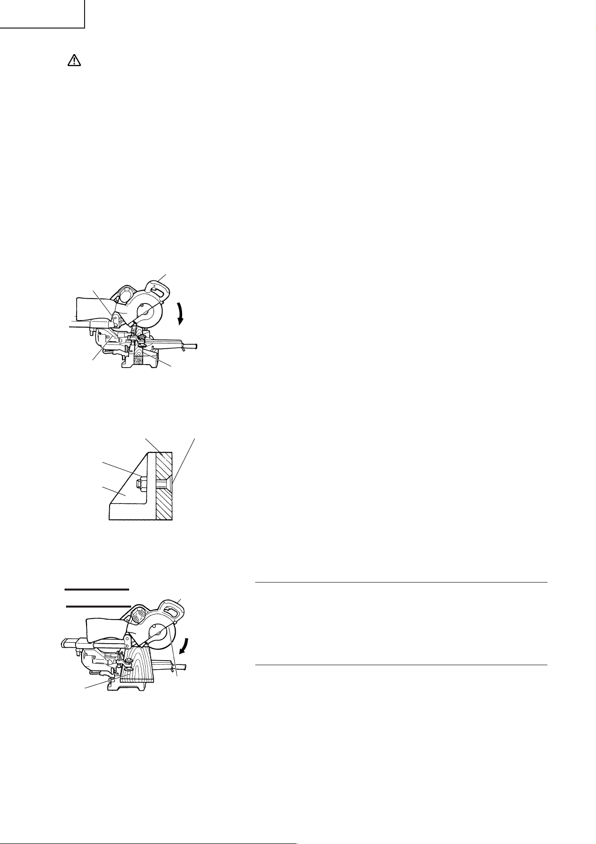
4. Cutting narrow workpieces (Press cutting)
Handle
Hinge
Press
Down
Slide the hinge down to holder (A), then tighten the slide securing
knob (see Fig. 2) as indicated in Fig. 28.
Lower the handle to cut the workpiece.
Using the power tool this way will permit cutting of workpieces of
up to 3-11/32" (85mm) square.
Holder (A)
Fig. 28
Workpiece
5. Cutting large workpieces
There may be case when a complete cutting cannot be done
Auxiliary
Board
6mm Flad Hd.
Screw
depending on the height of workpiece. In this case, mount an
auxiliary board with the 6mm flat head screws and the 6mm nuts
using the 7mm holes on the fence surface (two holes on each side).
6mm Nut
(Fig. 29)
Refer to page 9 "SPECIFICATIONS" for the thickness of the auxiliry
Fence
Fig. 29
board.
6. Cutting wide workpieces (Slide cutting)
(1)
1 Pull Forward
3 Push Rearward to Cut
▲
Workpiece
▲
Handle
2 Press
Down
Fig. 30
Workpieces up to 3-11/32" (85mm) high and 12-9/32" (312mm) wide:
Loosen the slide securing knob (see Fig. 2), grip the handle and
slide the saw blade forward.
Then press down on the handle and slide the saw blade back to
cut the workpiece as indicated in Fig. 30. This facilitates cutting
of workpieces of up to 3-11/32" (85mm) in height and 12-9/32"
(312mm) in width.
(2) Workpieces up to 3-9/16" (90mm) high and 11" (280mm) wide:
Workpieces of up to 3-35/64" (90mm) in height and up to 11"
(280mm) in width can be cut in the same manner as described
in paragraph 6-(1) above.
20
Page 21
CAUTION: * When cutting a workpiece of 3-11/32" (85mm) height, adjust the lower limit position
of the motor head so that the gap between the lower edge of the motor head and
the workpiece will be 3/32" to 1/8" (2 to 3mm) at the lower limit position.
* If the handle is pressed down with excessive or lateral force, the saw blade may
vibrate during the cutting operation and cause unwanted cutting marks on the
workpiece, thus reducing the quality of the cut.
Accordingly, press the handle down gently and carefully.
* In slide cutting, gently push the handle back (rearwards) in a single, smooth
operation.
Stopping the handle movement during the cut will cause unwanted cutting marks
on the workpiece.
WARNING: *For slide cutting, follow the procedures indicated above in Fig. 30.
Forward slide cutting (toward the operator) is very dangerous because the saw
blade could kick upward from the workpiece. Therefore, always slide the handle
away from the operator.
* Always return the carriage to the full rear position after each crosscut operation in
order to reduce the risk of injury.
* Never put your hand on the side handle during the cutting operation because the
saw blade comes close to the side handle when the motor head is lowered.
7. Bevel cutting procedures
English
Fixing pin
Holder (A)
Clamp Lever
(1) Loosen the clamp lever and bevel the saw blade to the left or to
the right.
When tilting the motor head to the right pull the fixing pin
towards the rear.
The clamp lever adopts a latchet system. When contacting the
work bench and the main body, pull the clamp lever in the
direction of the arrow mark as illustrated in Fig. 31, and change
the direction of the clamp lever.
(2) Adjust the bevel angle to the desired setting while watching
the bevel angle scale and indicator, then secure the clamp lever.
Bevel Scale
Indicator
(for left bevel scale)
Fig. 31
Tighten
Pull
Loosen
(3) Follow the procedures indicated in paragraphs 4,5 and 6 above. For maximum dimensions for bevel
cutting, refer to “SPECIFICATIONS” table on page 9.
WARNING: When the workpiece is secured on the left or right side of the blade, the short cut-off
portion will come to rest on the right or left side of the saw blade. Always turn the
power off and let the saw blade stop completely before raising the handle from the
workpiece.
If the handle is raised while the saw blade is still rotating, the cut-off piece may
become jammed against the saw blade causing fragments to scatter about
dangerously.
When stopping the bevel cutting operation halfway, start cutting after pulling back
the motor head to the initial position.
Starting from halfway, without pulling back, causes the safety cover to be caught in
the cutting groove of the workpiece and to contact the saw blade.
CAUTION: When cutting a workpiece of 2-3/8" (60mm) height in the left 45° bevel cutting position
or a workpiece of 1-3/8" (35mm) height in the right 45° bevel cutting position, adjust
the lower limit position of the motor head so that the gap between the lower edge of
the motor head and the workpiece will be 5/64" to 1/8" (2 to 3mm) at the lower limit
position (refer to “3. Checking the saw blade lower limit position” on page 13).
21
Page 22
English
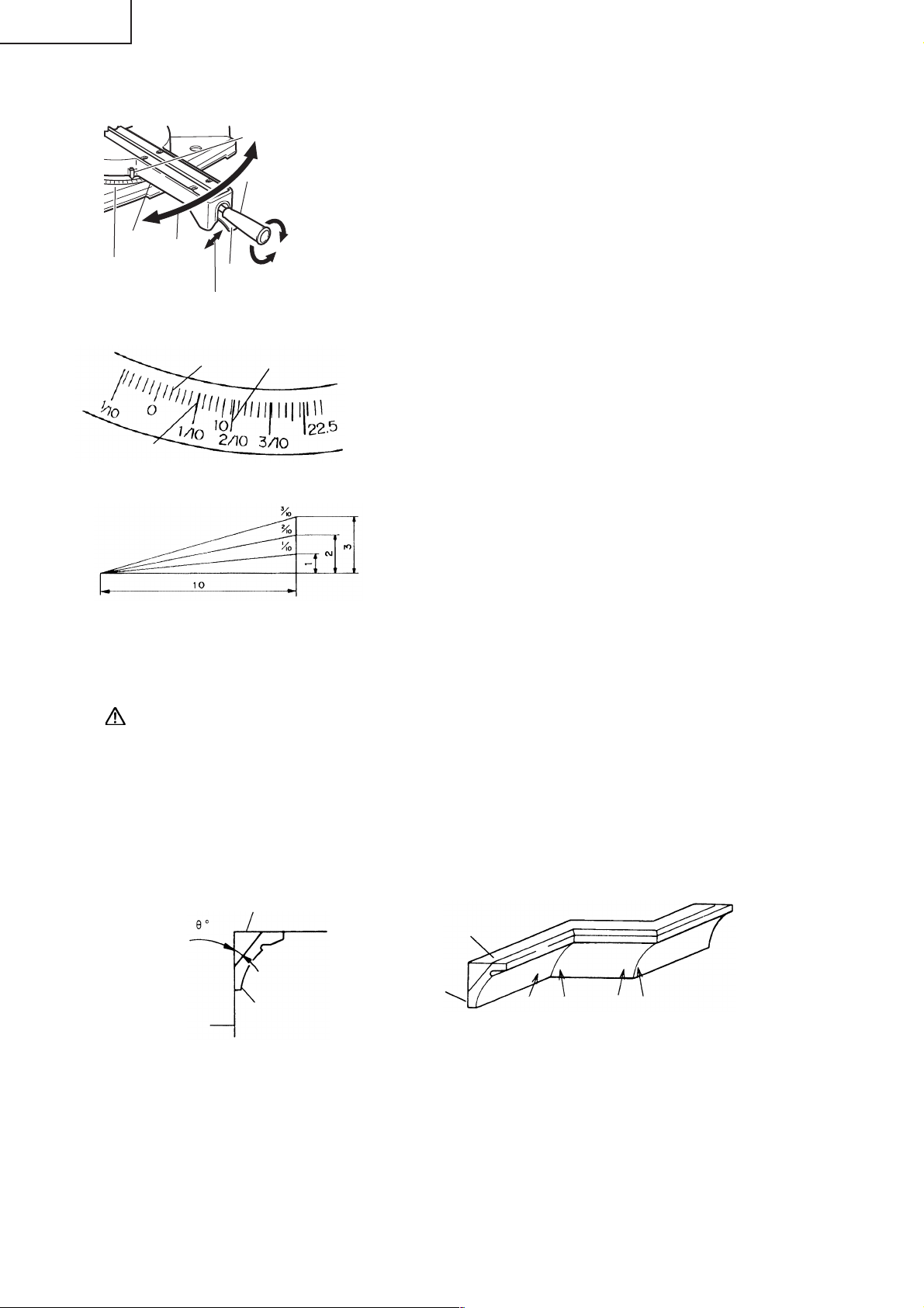
8. Miter cutting procedures
Turntable
Turn the
Miter Scale
Grade Scale
turntable
Angle Scale
Lever
Pull up
Fig. 32
Miter Scale
Fig. 33
Indicator
(For miter scale)
Side Handle
Tighten
Loosen
a
(1) Loosen the side handle and pull up the lever for angle stoppers.
Then, adjust the turntable until the indicator aligns with desired
setting on the miter scale (Fig. 32).
(2) Re-tighten the side handle to secure the turntable in the desired
position.
(3) The miter scale (Fig. 33) indicates both the cutting angle on the
angle scale and the gradient on the grade scale.
(4) The gradient, which is the ratio of the height to the base of the
triangular section to be removed, may be used for setting the
miter scale instead of the cutting angle, if desired (see Fig. 33).
(5) Therefore, to cut a workpiece at a grade of 2/10, set the indicator
to position a as indicated in Fig. 33.
NOTE: * Positive stops are provided at the right and left of the 0°
center setting, at 15°, 22.5°, 31.6° and 45° settings.
Check that the miter scale and the tip of the indicator
are properly aligned.
* Operation of the saw with the miter scale and indicator
out of alignment, or with the side handle not properly
tightened, will result in poor cutting precision.
Fig. 34
9. Compound cutting procedures
Compound cutting can be performed by following the instructions in 7 and 8 above. For maximum
dimensions for compound cutting, refer to “SPECIFICATIONS” table on page 9.
CAUTION: Always secure the workpiece with the right or left hand and cut it by sliding the
round portion of the saw backwards with the left hand.
It is very dangerous to rotate the turntable to the left during compound cutting
because the saw blade may come into contact with the hand that is securing the
workpiece.
In case of compound cutting (angle + bevel) by left bevel, turn the sub-fence
counterclockwise, and engage in the cutting operation.
10. Crown molding cutting procedures
Fig. 35 shows two common crown molding types having angles of (θ) 38° and 45°.
For the typical crown molding fittings, see Fig. 36.
A upper surface
Ceiling
B lower surface
Wall
Fig. 35 Fig. 36
Wall
Ceiling
1
2
Inside corner Outside corner
34
The table below shows the miter angle and the bevel angle settings that are ideal for the two crown
molding types.
NOTE: For convenience, positive stops are provided for the miter setting (left and right 31.6°) positions.
For miter cut setting
If the turntable has been set to either of the angles described, move the turntable adjusting side handle
a little to the right and left to stabilize the position and to properly align the miter angle scale and the tip
of the indicator before the operation starts.
22
Page 23
For bevel cut setting
Move handle on bevel section to the left and check that the position is stable and that the bevel angle
scale and the tip of the indicator are properly aligned. Then tighten the clamp lever.
English
Type of
Crown
Molding
45° Type
38° Type
To process crown molding at
positions 1 and 4 in Fig. 36.
Miter Angle
Setting
right 35.3°
mark)
(
right 31.6°
mark)
(
Bevel Angle
Setting
left 30°
mark)
(
left 33.9°
mark)
(
To process crown molding at
positions 2 and 3 in Fig. 36.
Miter Angle
Setting
left 35.3°
mark)
(
left 31.6°
mark)
(
Bevel Angle
Setting
left 30°
mark)
(
left 33.9°
mark)
(
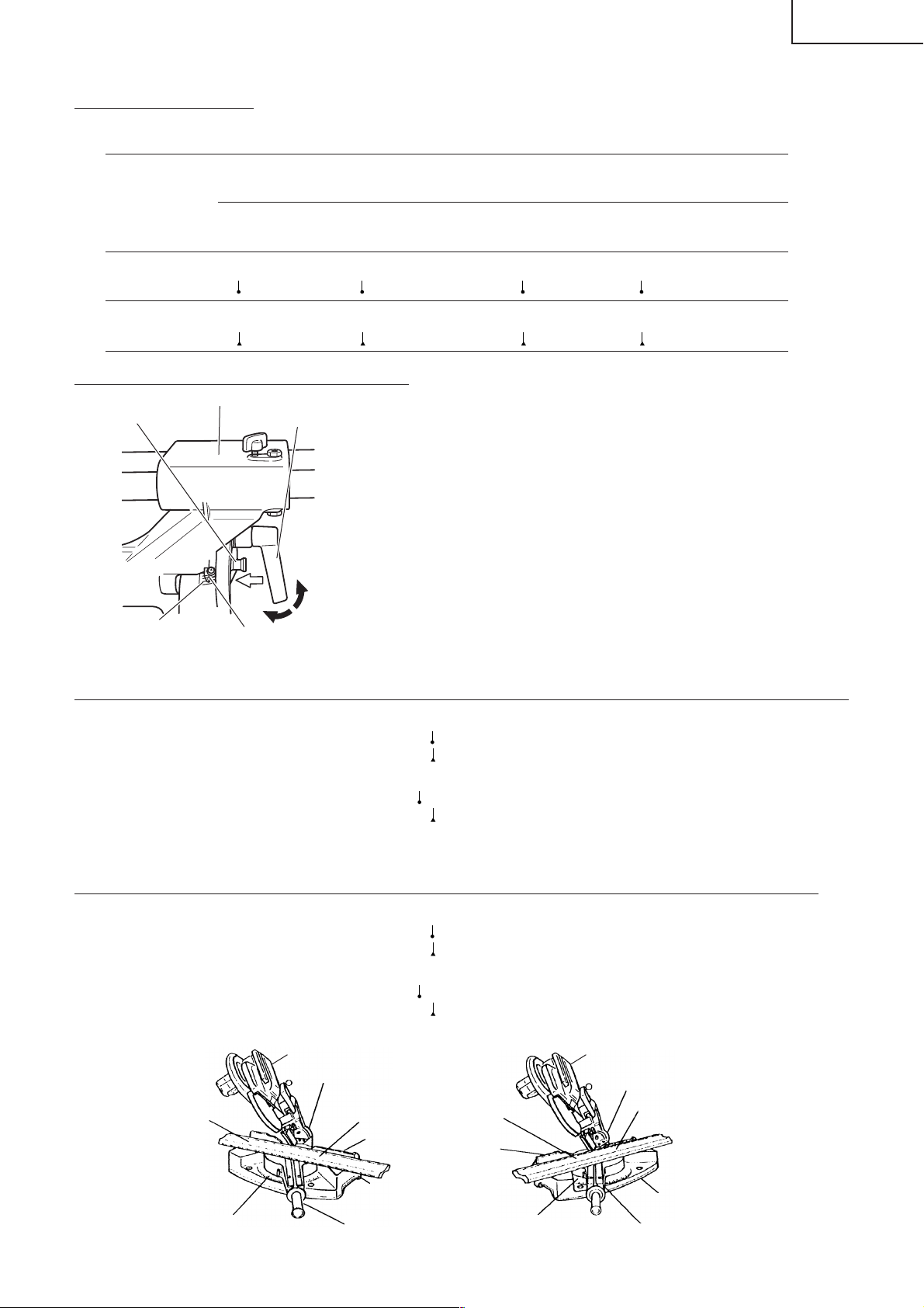
30° and 33.9° left slant setting method
Holder (A)
Fixing pin
Bevel Scale
Fig. 37
Clamp Lever
Push
Indicator
(for left bevel scale)
Tighten
Loosen
(1) Setting to cut crown moldings at positions 1 and 4 in Fig. 36 (see Fig. 38; tilt the motor head to the left):
(1) Loosen the clamp lever and slant to the left a little at a time
while pushing the fixing pin into the main unit. At this time, the
fixing pin will enter one step and fit into the 30° left slant and
33.9° left slant setting slots.
(2) With the fixing pin in the slot as described above, setting to the
30° left slant position is possible by pushing to the right side.
(3) Also, with the fixing pin in the slot as described above, setting
to the 33.9° left slant position is possible by pushing to the left
side.
(4) Look at the bevel scale and indicator to recheck whether or not
the settings match and then tighten the clamp lever.
1 Turn the turntable to the right and set the Miter Angle as follows:
* For 45° type crown moldings: 35.3° (
mark)
* For 38° type crown moldings: 31.6° ( mark)
2 Tilt the motor head to the left and set the Bevel Angle as follows:
* For 45° type crown moldings: 30° (
* For 38° type crown moldings: 33.9° (
mark)
mark)
3 Position the crown molding so that the upper surface (A in Fig. 35) contacts the fence as indicated
in Fig. 40.
(2) Setting to cut crown moldings at positions 2 and 3 in Fig. 36 (see Fig. 39; tilt the head to the left):
1 Turn the turntable to the left and set the Miter Angle as follows:
* For 45° type crown moldings: 35.3° (
mark)
* For 38° type crown moldings: 31.6° ( mark)
2 Tilt the head to the left and set the Bevel Angle as follows:
* For 45° type crown moldings: 30° (
mark)
* For 38° type crown moldings: 33.9° ( mark)
3 Position the crown molding so that the lower surface (B in Fig. 35) contacts the fence as in Fig. 41.
Head Head
Bevel Angle Scale
1
4
Fence
2
Fence
Bevel Angle Scale
3
Base
Miter Angle Scale Miter Angle ScaleTurntable Turntable
Fig. 38 Fig. 39
Base
23
Page 24
English
Fence
A
B
Table on Base
Fig. 40 Fig. 41
Fence
B
Table on Base
A
(3) Setting to cut crown moldings at positions 1 and 4 in Fig. 36 (see Fig. 42; tilt the head to the right):
1 Turn the turntable to the right and set the Miter Angle as follows:
* For 45° type crown moldings: 35.3° (
* For 38° type crown moldings: 31.6° (
mark)
mark)
2 Tilt the head to the right and set the Bevel Angle as follows:
* For 45° type crown moldings: 30° (
* For 38° type crown moldings: 33.9° (
mark)
mark)
3 Position the crown molding so that the upper surface (B in Fig. 35) contacts the fence as indicated
Fig. 44.
(4) Setting to cut crown moldings at positions 2 and 3 in Fig. 36 (see Fig. 43; tilt the head to the right):
1 Turn the turntable to the left and set the Miter Angle as follows:
* For 45° type crown moldings: 35.3° (
* For 38° type crown moldings: 31.6° (
mark)
mark)
2 Tilt the head to the right and set the Bevel Angle as follows:
* For 45° type crown moldings: 30° (
mark)
* For 38° type crown moldings: 33.9° ( mark)
3 Position the crown molding so that the lower surface (A in Fig. 35) contacts the fence as in Fig. 45.
Head
Head
4
Miter Angle
Scale
Fig. 42 Fig. 43
Fence
B
Table on Base
Fig. 44 Fig. 45
Turntable
Bevel Angle Scale
1
Fence
Base
A
3
Fence
Turntable
Fence
A
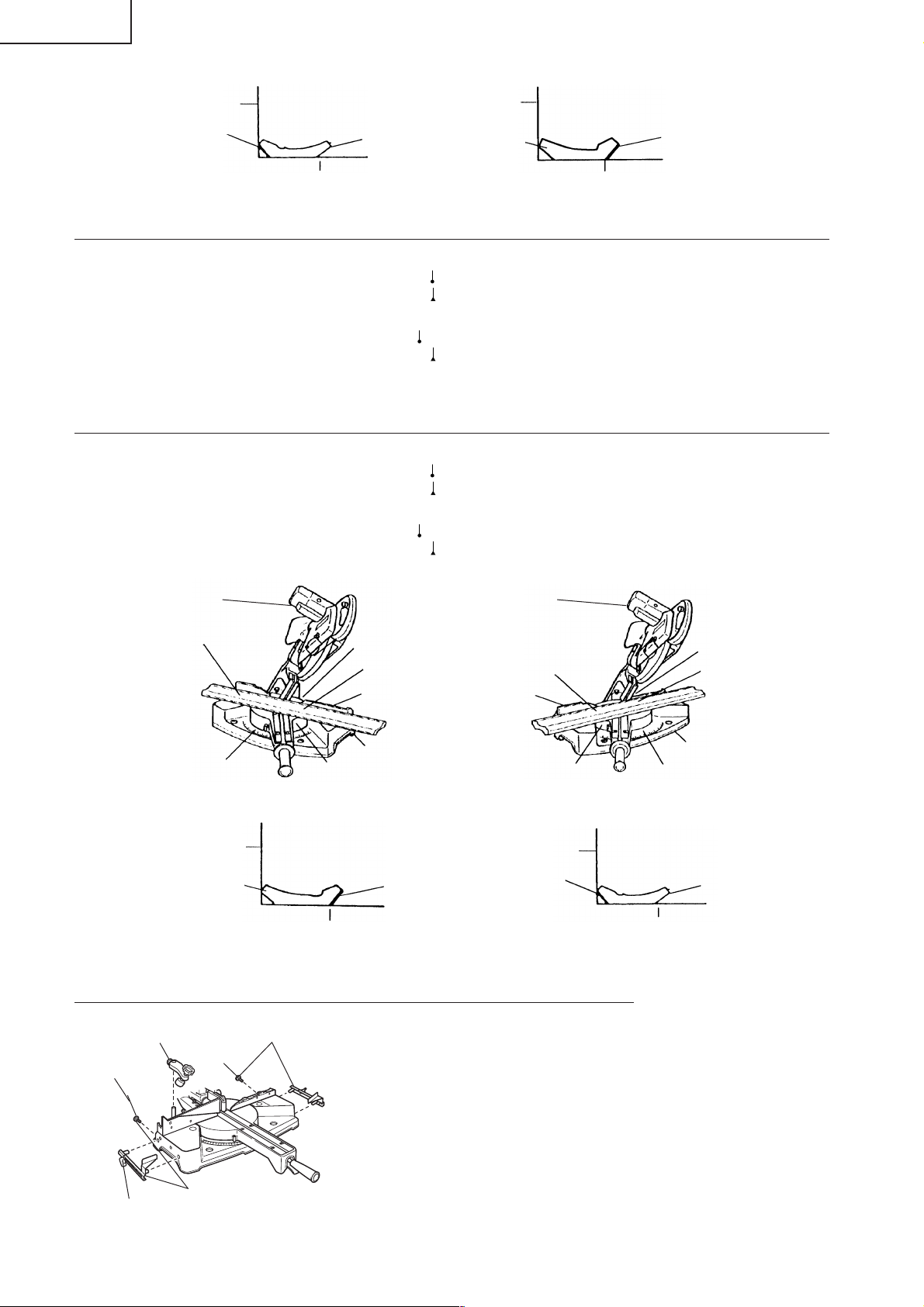
Cutting method of crown molding without tilting the saw blade.
Crown molding Vise Ass’y
(optional accessories)
6mm Knob Bolt
6mm Wing Bolt
Crown molding Stopper (L)
(optional accessories)
Crown molding Stopper (R)
(optional accessories)
6mm Knob
Bolt
Fig. 46-a
(1) Crown molding Stopper (L) and (R) (optional accessories) allow
easier cuts of crown molding without tilting the saw blade.
Install them in the base both-sides side to be shown in Fig. 46a. After inserting Tighten the 6mm knob bolts to secure the
crown molding Stoppers.
[Optional accessories used]
• Crown molding Vise Ass’y (Include Crown molding Stopper
(L))
• Crown molding Stopper (L)
• Crown molding Stopper (R)
Base
Miter Angle
Scale
Table on Base
Bevel Angle Scale
2
B
24
Page 25
English
Crown molding Vise Ass’y
(optional accessories)
6mm Knob Bolt
Knob
V-Groove
(2) The crown molding vise (B) (Optional accessory) can be
mounted on either the left fence (Fence (B)) or the right fence
(Fence (A)). It can unite with the slope of the crown molding
and vice can be pressed down.
Then turn the upper knob, as necessary, to securely attach the
crown molding in position. To raise or lower the vise assembly,
Groove
Fence
first loosen the 6mm knob bolt. As shown in Fig. 46-b, the vise
shaft has three locking grooves into which the tip of the 6mm
wing bolt is designed to fit in order to lock the screw holder in
6mm wing bolt
Crown molding
Crown molding Stopper (L)
Crown molding Stopper (R)
(optional accessories)
Fig. 46-b
the desired position.
To ensure that the tip of the 6mm wing bolt is properly aligned
with the desired locking groove on the vise shaft, simply align
the upper surface of the fence to either of three v-grooves on
the vise shaft surface or to the lower surface of the screw holder.
Therefore, the vise assembly can be attached in eigher of three
positions to ensure proper height adjustment.
After adjusting the height, firmly tighten the 6mm wing bolt;
then turn the upper knob, as necessary, to securely attach the
the crown molding in position. (see Fig. 46-b)
WARNING: Always firmly clamp or vise to secure the crown molding to the fence; otherwise the
crown molding might be thrust from the table and cause bodily harm.
Do not bevel cutting. The main body or saw blade may contact the sub fence, resulting
in an injury.
CAUTION: Always confirm that the motor head (see Fig. 1) does not contact the crown molding
vise ass’y when it is lowered for cutting. If there is any danger that it may do so,
loosen the 6mm knob bolt and move the crown molding vise ass’y to a position
where it will not contact the saw blade.
Position crown molding with its WALL CONTACT EDGE against the guide fence and its CEILING CONTACT
EDGE against the crown molding Stoppers as shown in Fig. 46-b.
Adjust the crown molding Stoppers according to the size of the crown molding.
Tighten the 6mm wing bolt to secure the crown molding Stoppers.
Refer to the lower table for the miter angle.
Position in Fig. 34 Miter angle Finished piece
For inside corner 1 Right 45° Save the right side of blade
2
Save the left side of blade
Left 45°
For outside corner 3 Save the right side of blade
4 Right 45° Save the left side of blade
Use the sub fence (A) (optional accessories) to secure the crown molding more firmly. (see Fig. 15)
11. Groove cutting procedures
Cut grooves with saw blade
a
b
Fig. 47 Fig. 48
8mm Depth
Adjustment Bolt
b
Bottom Line of
the Groove
Grooves in the workpiece can be cut as indicated in Fig. 47 by adjusting the 8mm depth adjustment
bolt.
8mm Wing Nut
Gear Case
Turntable
Cutting depth adjustment procedure:
(1) Loosen the 8mm wing nut and turn the 8mm depth adjustment bolt by hand.
25
Page 26
English
(2) Adjust to the desired cutting depth by setting the distance between the saw blade and the surface of
the base (see b in Fig. 47).
(3) The 8mm wing nut must be properly tightened after the adjustment has been completed.
NOTE: When cutting a single groove at either end of the workpiece, remove the unneeded portion
with a chisel.
12. Cutting easily-deformed materials, such as aluminum sash
Materials such as aluminum sash can easily deform when tightened too much in a vise assembly. This
will cause inefficient cutting and possible overload of the motor.
When cutting such materials, use a wood plate to protect the workpiece as shown in Fig. 49-a. Set the
wood plate near the cutting section.
When cutting aluminum materials, coat the saw blade with cutting oil (non-combustible) to achieve
smooth cutting and a fine finish.
In addition, in case of a U-shaped workpiece, use the wood plate as shown in Fig. 49-b to ensure
stability in the lateral direction, and clamp it near the cutting section of the workpiece and tighten it
using both the vise assembly and the clamp available in the market.
Vise
Fence
6mm Knob Bolt
Fig. 49-a Fig. 49-b
Assembly
Wood
Plate
Aluminum
Sash
Wood Plate
13. How to use the dust bag (Standard accessory)
Dust Bag
Duct
Right Angle
Base
Fig. 50
(1) When the dust bag has become full of sawdust, dust will be
blown out of the dust bag when the saw blade rotates.
Check the dust bag periodically and empty it before it becomes
full.
(2) During bevel and compound cutting, attach the dust bag at a
right angle to the base surface as shown in Fig. 50.
CAUTION: Empty the dust bag frequently to prevent the duct and the safety cover from becoming
clogged.
Sawdust will accumulate more quickly than normal during bevel cutting.
Fence
Wood Plate
Vise Assembly
Clamp
Wood Plate
Aluminum Sash
SAW BLADE MOUNTING AND DISMOUNTING
WARNING: *To prevent an accident or personal injury, always turn off the trigger switch and
disconnect the power plug from the receptacle before removing or installing a saw
blade.
If cutting work is done in a state where the bolt is not sufficiently tightened, the bolt can
get loose, the blade can come off, and the safety cover can get damaged, resulting in
injuries.
Also, check that the bolts are properly tightened before plugging the power plug into
the receptacle.
* If the bolts are attached or detached using tools other than the 10mm box wrench
(standard accessory), excessive or improperly tightening occurs, resulting in injury.
1. Mounting the saw blade (Fig. 51-a, Fig. 51-b and Fig. 51-c)
(1) Use the accessory 10mm box wrench to loosen the 6mm bolt fastening the spindle cover and then
remove the spindle cover.
(2) Press in spindle lock and loosen bolt with 10mm box wrench (standard accessory).
Since the bolt is left-hand threaded, loosen by turning it to the right as shown in Fig. 51-c.
26
Page 27
English
NOTE: If the spindle lock cannot be easily pressed in to lock the spindle, turn the bolt with 10mm
box wrench (standard accessory) while applying pressure on the spindle lock.
The saw blade spindle is locked when the spindle lock is pressed inward.
(3) Remove the bolt and washer (D)
10mm
Box Wrench
Loosen
6mm Bolt
Spindle
Cover
Fig. 51-a Fig. 51-b Fig. 51-c
10mm
Box Wrench
Spindle Lock
Tighten
Loosen
Bolt
Washer (D)
(4) Lift the safety cover and mount the saw blade.
WARNING: When mounting the saw blade, confirm that the rotation indicator mark on the saw
blade and the rotation direction of the gear case(see Fig. 1) are properly matched.
(5) Thoroughly clean washer (D) and the bolt, and install them onto the saw blade spindle.
(6) Press in the spindle lock and tighten the bolt by turning it to the left by standard accessorie’s wrench
(10mm box wrench) as indicated in Fig. 51-c.
CAUTION: * A dust guide is installed inside behind the gear case.
When removing or installing the saw blade, do not make contact with the dust
guide. Contact may break or chip saw blade tips.
* Confirm that the spindle lock has returned to the retract position after installing or
removing the saw blade.
* Tighten the bolt so it does not come loose during operation.
Confirm the bolt has been properly tightened before the power tool is started.
2. Dismounting the saw blade
Dismount the saw blade by reversing the mounting procedures described in paragraph 1 above.
The saw blade can easily be removed after lifting the safety cover.
CAUTION: Never attempt to install saw blades larger than 10" (255mm) in diameter.
Always install saw blades that are 10" (255mm) in diameter or less.
OVERLOAD PROTECTIVE DEVICE FOR POLY-V-BELT
The power of the motor is transmitted to the saw blade by a Poly-V-Belt. When the Poly-V-Belt becomes
overloaded, the overload protective device cuts off the current to stop the motor.
In this case turn the switch off immediately and raise the handle to its initial position. Then turn the switch
on and after running the tool for 20 seconds without a load for cooling of the motor. Then start the cutting
operation. The Poly-V-Belt or the motor will be damaged if the overload protective device turns off frequently.
CAUTION: When the overload protective device stops the motor, the motor will start by turning the
switch on after turning it off. When turning the switch on, make sure that the saw blade
is not halfway in the material.
MAINTENANCE AND INSPECTION
WARNING: To avoid an accident or personal injury, always confirm that the trigger switch is turned
OFF and the power plug has been disconnected from the receptacle before performing
any maintenance or inspection of this tool.
1. Inspecting the saw blade
Always replace the saw blade immediately upon the first sign of deterioration or damage.
A damaged saw blade can cause personal injury and a worn saw blade can cause ineffective operation
and possible overload to the motor.
27
Page 28
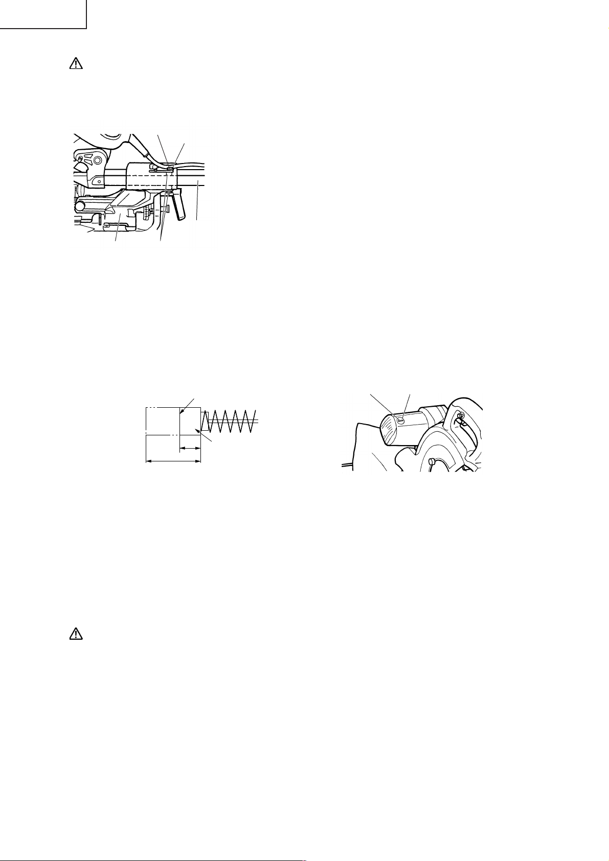
English
CAUTION: Never use a dull saw blade. When a saw blade is dull, its resistance to the hand
pressure applied by the tool handle tends to increase, making it unsafe to operate
the power tool.
2. Adjusting a loose slide pipe
8mm Hex. Socket
Set Screw
Slide Pipe (A)
8mm Nut
After extended use of the power tool, the slide pipe (A) and the
bushing can become loose due to vibration. Never operate the tool
if any components are loose to avoid personal injury.
(1) Loosen the 8mm nut and tighten the two 8mm hexagon socket
set screws until the power tool operates smoothly without
looseness.
(2) Properly tighten the 8mm nut after completing these
adjustment.
Holder (A)
Bushing
Fig. 52
3. Inspecting the carbon brushes (Fig. 53 and Fig. 54)
The carbon brushes in the motor are expendable parts.
If the carbon brushes become excessively worn, motor trouble might occur.
Therefore, inspect the carbon brushes periodically and replace them when they have become worn to
the wear limit line as shown in Fig. 53.
Also, keep the carbon brushes clean so that they will slide smoothly within the brush holders.
The carbon brushes can easily be removed after removal of the brush caps (see Fig. 54) with a slotted
(minus) screwdriver.
Wear Limit Line
43
No. 43 indicates the last
1/4" (6mm)
11/16" (17mm)
Fig. 53 Fig. 54
two numbers of carbon
brush Code No.
Brush CapGroove for Driver
4. About Handling the Motor (see Fig. 1)
Winding of the motor is said to be the heart of this tool. Exercise utmost caution not to damage the
winding by exposing it to wash oil or water.
NOTE: Accumulation of dust and the like inside the motor can result in a malfunction.
After using the motor for 50 hours or so, carry out no-load running, and blow in the dry air
from a wind hole at the motor's rear. Such action is effective to discharge dust and the like.
5. Inspecting the screws
Regularly inspect each component of the power tool for looseness.
Re-tighten screws on any loose part.
WARNING: To prevent personal injury, never operate the power tool if any components are loose.
6. Inspecting the safety cover for proper operation
Before each use of the tool, test the safety cover (see Fig. 7) to assure that it is in good condition and
that it moves smoothly.
Never use the tool unless the safety cover operates properly and it is in good mechanical condition.
7. Storage
After operation of the tool has been completed, check that the following has been performed:
(1) Trigger switch is in OFF position,
(2) Power plug has been removed from the receptacle,
(3) Lock-off button has been removed and stored in a secure place.
When the tool is not in use, keep it stored in a dry place out of the reach of children.
28
Page 29
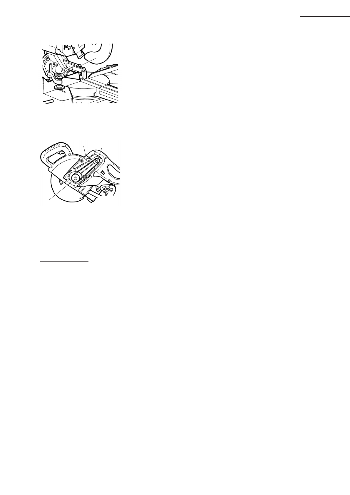
8. Replacement of guard (C)
Guard
Fig. 55
9. Replacement of Poly-V-Belt
Poly-V-Belt
Pulley (A)
English
After long-term use, the blade slot in the guard may widen and
require replacement. If the blade slot should widen, replace the
guard with a new one. After replacing, make a groove on it. Refer
to “1. Cutting a groove on the guard” on page 13.
The power of the motor is transmitted to the saw blade by a PolyV-Belt. When the Poly-V-Belt is broken or damaged, remove the
belt cover by loosening the two 5mm screws (see Fig. 2) and replace
the damaged one with the new one.
When connecting the belt on pulleys, first connect 2 or 3 teeth of
Poly-V-Belt to the grooves of the pulley (A) and pulley (B). Then
turning the pulley (A) and pulley (B), connect all 10 teeth of the belt
to the pulleys.
Pulley (B)
Fig. 56
10. Lubrication
Lubricate the following sliding surfaces once a month to keep the power tool in good operating condition
for a long time (see Fig. 1 and Fig. 2). Use of machine oil is recommended.
Oil supply points:
* Rotary portion of hinge
* Rotary portion of vise assembly
* Rotary portion of holder (A)
11. Cleaning
Periodically remove chips, dust and other waste material from the surface of the power tool, especially
from the inside of the safety cover with a damp, soapy cloth. To avoid a malfunction of the motor,
protect it from contact with oil or water.
(Only Model C10FSH)
If the laser line becomes invisible due to chips and the like adhered onto the window of the laser
marker's light-emitting section, wipe and clean the window with a dry cloth or a soft cloth moistened
with soapy water, etc.
SERVICE AND REPAIRS
All quality power tools will eventually require servicing or replacement of parts because of wear from
normal use. To assure that only authorized replacement parts will be used and that the double insulation
system will be protected, all service (other than routine maintenance) must be performed by an AUTHORIZED
HITACHI POWER TOOL REPAIR CENTER ONLY.
NOTE: Specifications are subject to change without any obligation on the part of HITACHI.
29
Page 30

Français
INFORMATIONS IMPORTANTES DE SÉCURITÉ
Lire et comprendre toutes les précautions de sécurité, les avertissements et les instructions de fonctionnement
dans ce mode d’emploi avant d’utiliser ou d’entretenir cet outil motorisé.
La plupart des accidents causés lors de l’utilisation ou de l’entretien de l’outil motorisé proviennent d’un
non respect des règles ou précautions de base de sécurité. Un accident peut la plupart du temps être évité
si l’on reconnaît une situation de danger potentiel avant qu’elle ne se produise, et en observant les procédures
de sécurité appropriées.
Les précautions de base de sécurité sont mises en évidence dans la section “SECURITE” de ce mode d’emploi
et dans les sections qui contiennent les instructions de fonctionnement et d’entretien.
Les dangers qui doivent être évités pour prévenir des blessures corporelles ou un endommagement de la
machine sont identifiés par AVERTISSEMENTS sur l’outil motorisé et dans ce mode d’emploi.
NE JAMAIS utiliser cet outil motorisé d’une manière qui n’est pas spécifiquement recommandée par HITACHI.
SIGNIFICATION DES MOTS D’AVERTISSEMENT
AVERTISSEMENT indique des situations potentiellement dangereuses qui, si elles sont ignorées,
pourraient entraîner la mort ou de sérieuses blessures.
PRECAUTION indique des situations dangereuses potentilles qui, si elles ne sont pas évitées, peuvent
entraîner de mineures et légères blessures ou endommager la machine.
REMARQUE met en relief des informations essentielles.
SECURITE
CONSIGNES DE SECURITE RELATIVES AUX OUTILS ÉLECTRIQUES
LIRE TOUS LES AVERTISSEMENTS ET TOUTES LES INSTRUCTIONS D’UTILISATION DU
MANUEL AVANT DE METTRE L’OUTIL EN SERVICE OU DE L’ENTRETENIR :
AVERTISSEMENT: Lorsqu’on utilise l’outil électrique, prendre toutes les précautions nécessaires
pour éviter au maximum tout risque de choc électrique ou autre blessure
physique.
En particulier, toujours respecter les consignes de sécurité suivantes :
1. TOUJOURS LAISSER LES PROTECTIONS EN PLACE ET LES MAINTENIR EN BON
ORDRE DE MARCHE.
2. TOUJOURS RETIRER LES CLAVETTES DE RÉGLAGE ET LES CLÉS AVANT DE METTRE
L’OUTIL EN MARCHE.
retirées de l’outil avant de le mettre en marche.
3. TOUJOURS MAINTENIR L’AIRE DE TRAVAIL PROPRE. Pour éviter tout risque de blessure, ne
pas encombrer l’aire de travail ni l’établi.
4. NE JAMAIS UTILISER L’OUTIL DANS UN ENVIRONNEMENT DANGEREUX. Ne jamais
utiliser l’outil électrique dans un endroit humide ou mouillé, et ne jamais l’exposer à la pluie. Toujours
veiller à ce que l’aire de travail soit suffisamment éclairée.
5. NE JAMAIS LAISSER LES ENFANTS NI AUCUNE AUTRE PERSONNE APPROCHER DE
L’AIRE DE TRAVAIL.
Toujours débrancher l’outil quand on s’en éloigne et veiller à ce que personne ne puisse pénétrer dans
l’aire de travail en mettant des verrous aux portes et aux interrupteurs principaux. Toujours retirer le
bouton de déverrouillage de l’outil et le ranger en lieu sûr lorsqu’on ne s’en sert pas.
6. NE JAMAIS FORCER L’OUTIL. Il effectuera le travail le meilleur et avec la sécurité maximale au
régime pour lequel il a été conçu.
Toujours vérifier que les clés et les clavettes de réglage sont bien toutes
Interdire l’accès de l’aire de travail à tout le monde (en particulier aux enfants).
30
Page 31

Français
7. TOUJOURS UTILISER LES OUTILS APPROPRIÉS. Ne jamais utiliser un outil ou un accessoire
pour un travail pour lequel il n’est pas conçu.
8. PORTER DES VÊTEMENTS APPROPRIÉS PENDANT LE TRAVAIL. Ne jamais porter de
vêtements lâches ni de gants, cravate, bagues, bracelets ni aucun autre bijou. Ils pourraient se coincer
dans les pièces en rotation. Toujours porter des chaussures anti-dérapantes, en particulier avec des
doigts de pied en acier. Porter un couvre-chef qui recouvre les cheveux longs.
9. TOUJOURS PORTER DES LUNETTES DE PROTECTION PENDANT LE TRAVAIL POUR
ÉVITER TOUT RISQUE DE BLESSURE DES YEUX.
protection suffisante parce que les verres ne sont pas faits en verre de sécurité. Par ailleurs, porter un
masque sur le visage pour accroître la sécurité, et un masque anti-poussière si le travail doit dégager
de la poussière.
Les lunettes ordinaires n’assurent pas une
10. TOUJOURS FIXER LA PIÈCE À LA GARDE OU À LA TABLE. Utiliser des dispositifs de serrage
ou un étau pour tenir la pièce. Cela sera plus sûr que de tenir la pièce à la main et libérera les deux
mains pour le travail.
11. NE JAMAIS TROP SE PENCHER. Toujours garder une bonne assise et un bon équilibre pendant
le travail.
12. TOUJOURS ENTRETENIR LES OUTILS AVEC SOIN. Maintenir les outils aiguisés et propres
pour optimiser le travail et la sécurité. Toujours suivre les instructions de graissage et de remplacement
des accessoires.
13. TOUJOURS DÉBRANCHER L’OUTIL avant un entretien et lors du remplacement des lames ou de
tout autre accessoire.
14. NE JAMAIS RISQUER UNE MISE EN MARCHE INOPINÉE LORSQU’ON BRANCHE
L’OUTIL.
dans la prise secteur.
Toujours vérifier que l’interrupteur est en position OFF avant de brancher la fiche d’alimentation
15. TOUJOURS UTILISER EXCLUSIVEMENT LES ACCESSOIRES RECOMMANDÉS POUR
L’OUTIL. Consulter le mode d’emploi pour la description des outils recommandés. Pour éviter tout
risque de blessure, utiliser exclusivement les accessoires recommandés pour cet outil.
16. NE JAMAIS MONTER SUR L’OUTIL.Pour éviter tout risque de blessures graves, ne pas incliner
l’outil, et veiller à ne pas toucher la lame par inadvertance.
17. TOUJOURS VÉRIFIER SI L’OUTIL A DES PIÈCES ENDOMMAGÉES AVANT DE
L’UTILISER.
l’outil pour s’assurer qu’ils fonctionneront correctement. Vérifier si toutes les pièces mobiles sont bien
alignées, non voilées, ou toute autre condition qui pourrait entraver leur bon fonctionnement. Toujours
réparer ou remplacer les protections ou les autres pièces endommagées avant d’utiliser l’outil.
Toujours vérifier si la protection et les autres composants sont endommagés avant d’utiliser
18. TOUJOURS VÉRIFIER LE SENS DE ROTATION DE LA LAME AVANT D’UTILISER L’OUTIL.
Toujours avancer la pièce dans l’outil contre le sens de rotation de la lame pour éviter tout risque de
blessure.
19. NE JAMAIS S’ÉLOIGNER DE L’OUTIL QUAND IL FONCTIONNE. LE METTRE HORS
TENSION.
hors tension quand on ne s’en sert pas. Toujours débrancher le cordon d’alimentation quand on ne se
sert pas de l’outil.
Ne pas s’éloigner de l’outil tant qu’il n’est pas complètement arrêté. Toujours mettre l’outil
20. L’outil n’est pas conçu pour des applications de fabrication en série, et il ne devra donc pas être utilisé
dans un environnement de fabrication en série.
21. Pour les réparations, utiliser exclusivement des pièces de rechange agréées.
22. Alimenter l’outil exclusivement sur un courant alternatif de 120 volts. Une tension ou une alimentation
incorrectes pourraient provoquer un mauvais fonctionnement de l’OUTIL ELECTRIQUE et provoquer
des blessures physiques ou des dommages matériels graves.
23. Ne jamais relever la lame de la pièce tant qu’elle n’est pas complètement arrêtée.
24. Toujours utiliser des supports extérieurs pour assurer la stabilité des longues pièces qui dépassent de
la table de la scie à onglet radiale.
25. Pour éviter tout risque de blessure, toujours ramener le chariot complètement vers l’arrière après chaque
coupe en travers.
26. FICHES POLARISÉES Pour réduire tout risque de choc électrique, l’appareil possède une fiche
polarisée (l’une des lames est plus large que l’autre). Cette fiche ne rentrera dans une prise polarisée
que dans un sens. Si la fiche ne rentre pas dans la prise, l’inverser. Si elle ne rentre toujours pas, faire
installer une prise appropriée par un électricien qualifié. Ne pas modifier la fiche de quelque façon que
ce soit.
31
Page 32

Français
Consignes de sécurité spéciales pour cet outil électrique
AVERTISSEMENT: Pour éviter tout risque de blessure, les consignes de sécurité spéciales suivantes
devront être respectées lors de l’utilisation de l’outil.
CHOSES A FAIRE
TOUJOURS OBSERVER LES CONSIGNES SUIVANTES POUR GARANTIR UNE
UTILISATION EN TOUTE SÉCURITÉ:
Bien lire le manuel et se familiariser avec les consignes de sécurité et les instructions d’utilisation de
1.
l’OUTIL ELECTRIQUE avant de l’utiliser.
2. Toujours vérifier que l’OUTIL ELECTRIQUE est propre avant de l’utiliser.
3. Toujours porter des vêtements bien ajustés et des chaussures anti-dérapantes (de préférence avec des
doigts de pied en acier) et des lunettes de protection lorsqu’on utilise l’OUTIL ELECTRIQUE.
4. Toujours manier l’OUTIL ELECTRIQUE avec soin. Si l’OUTIL ELECTRIQUE tombe ou qu’il heurte un
objet dur, il risque de se déformer, de se fendiller ou autre dommage.
5. Toujours cesser immédiatement d’utiliser la scie si l’on remarque quelque chose d’anormal.
6. Toujours vérifier que les pièces sont toutes correctement montées et fixées avant d’utiliser l’outil.
7. Pour le remplacement de la lame, toujours vérifier que le régime nominal de la nouvelle lame convient
pour l’outil.
8. Toujours mettre l’outil hors tension et attendre que la lame ait complètement cessé de tourner avant
tout remplacement ou tout réglage.
9. Pendant une coupe avec chariot, toujours repousser la lame loin de l’opérateur.
10. Toujours visser ou fixer la pièce sur la garde, pour qu’elle ne risque pas d’être éjectée de la table et de
provoquer des blessures.
11. Pendant une coupe d’onglet ou de biseau, toujours attendre que la lame ait complètement cessé de
tourner avant de la relever.
12. Toujours faire un essai avant d’utiliser la scie pour un nouvel usage.
13. Toujours manipuler la scie avec soin lorsqu’on la démonte ou qu’on la monte.
14. Toujours vérifier qu’il n’y a ni clou ni aucun autre corps étranger dans la pièce avant de commencer une
coupe.
15. Toujours éloigner les mains du trajet de lame.
16. Toujours vérifier que le carter de sécurité est en place avant d’utiliser la scie.
17. Toujours vérifier que le carter de sécurité ne gêne pas le mouvement du chariot avant toute coupe avec
chariot.
18. Inspecter périodiquement les cordons d’alimentation.
19. Le cas échéant, toujours vérifier que l’on utilise des cordons et des rallonges du type et de la longueur
voulus avant de mettre l’outil en marche.
20. Toujours vérifier que les évents d’aération du moteur sont complètement dégagés avant d’utiliser l’outil.
21. Toujours attendre que le moteur ait atteint sa vitesse de régime avant d’entamer une coupe.
22. Toujours maintenir les poignées sèches, propres et sans huile ni graisse. Tenir l’outil fermement pendant
le travail.
23. Toujours utiliser des supports extérieurs pour soutenir les pièces longues qui dépassent de la table de
la scie à coupe d’onglet.
24. Toujours commencer par s’assurer que la pièce est correctement fixée dans un étau.
25. Le mode d’emploi fourni avec l’outil explique à l’utilisateur comment fixer l’outil sur la structure de
support si, pendant un fonctionnement normal, l’outil a tendance à se renverser, à glisser, ou à se
déplacer sur la surface de support.
32
Page 33

Français
CHOSES A NE PAS FAIRE
POUR GARANTIR UNE UTILISATION EN TOUTE SÉCURITÉ, NE JAMAIS VIOLER LES
CONSIGNES SUIVANTES:
Ne jamais utiliser l’OUTIL ELECTRIQUE si l’on ne comprend pas bien les instructions de ce manuel.
1.
2. Ne jamais s’éloigner de l’OUTIL ELECTRIQUE sans débrancher auparavant son cordon d’alimentation.
3. Ne jamais utiliser l’OUTIL ELECTRIQUE quand on est fatigué, après avoir pris des médicaments ou
consommé des boissons alcoolisées.
4. Ne jamais utiliser l’OUTIL ELECTRIQUE pour des applications non spécifiées dans ce mode d’emploi.
5. Ne jamais faire fonctionner l’outil si l’on porte des vêtements lâches, une cravate ou des bijoux, ou sans
se couvrir les cheveux, pour éviter qu’ils ne se prennent dans les pièces mobiles.
6. Ne jamais approcher les mains de la lame.
7. Ne jamais toucher les pièces en mouvement, y compris la lame, pendant le fonctionnement de la scie.
8. Ne jamais retirer les dispositifs de sécurité ni les protections de lame; l’utilisation de l’outil serait
dangereuse sans ces pièces.
9. Ne jamais verrouiller le carter de sécurité; toujours vérifier qu’il glisse régulièrement avant d’utiliser
l’outil.
10. Ne jamais endommager le cordon d’alimentation de l’outil.
11. Quand l’OUTIL ELECTRIQUE est branché, ne jamais tenter de le déplacer avec le doigt sur l’interrupteur
de marche.
12. Ne jamais utiliser l’OUTIL ELECTRIQUE si l’interrupteur de marche ne fonctionne pas correctement.
13. Ne jamais utiliser l’OUTIL ELECTRIQUE si le logement en plastique ou la poignée sont déformés ou
fendillés.
14. Ne jamais utiliser l’OUTIL ELECTRIQUE à proximité d’un liquide ou d’un gaz inflammable, car les étincelles
pourraient provoquer une explosion.
15. Ne jamais nettoyer les composants en plastique avec des solvants car cela risquerait de dissoudre le
plastique.
16. Ne jamais faire fonctionner la scie si les protections de lame ne sont pas toutes en place.
17. Ne jamais relever la lame de la pièce tant que la lame n’est pas complètement arrêtée.
18. Lors d’une coupe avec chariot, ne jamais tirer la poignée vers l’opérateur car cela pourrait provoquer
un retour de lame. Toujours repousser la poignée loin de l’opérateur d’un mouvement régulier et
ininterrompu.
19. Ne jamais amener les membres à l’intérieur de la ligne à côté du signe d’avertissement “ ” quand
l’outil fonctionne. Cela pourrait être dangereux.
20. Ne jamais utiliser de lames de type abrasif avec cette scie.
21. Ne jamais exposer à la pluie ni utiliser dans un endroit humide.
22. Ne jamais couper de métaux ferreux ni de maçonnerie.
AVERTISSEMENT
POUR VOTRE PROPRE SÉCURITÉ, LISEZ ATTENTIVEMENT CE MODE D’EMPLOI AVANT
D’UTILISER LA SCIE À COUPE D’ONGLET RADIALE.
Toujours porter des lunettes de protection lorsqu’on utilise la scie à coupe d’onglet radiale.
1.
2. Toujours éloigner les mains du trajet de lame.
3. Ne jamais faire fonctionner la scie si les protections ne sont pas en place.
4. Ne jamais effectuer d’opération à la volée avec la scie à coupe d’onglet radiale.
5. Ne jamais s’approcher de la lame.
6. Toujours mettre la scie hors tension et attendre que la lame ait complètement cessé de tourner avant de
déplacer la pièce ou de modifier les réglages.
33
Page 34

Français
7. Toujours débrancher l’alimentation avant de remplacer la lame ou d’entretenir l’outil.
8. Le diamètre de la lame est de 10" (255mm).
9. La vitesse à vide est de 3800/min.
10. Pour réduire tout risque de blessure, ramener le chariot complètement vers l’arrière après chaque
opération de coupe.
PIECES DE RECHANGE
Pour les réparations, utiliser exclusivement des pièces de rechange identiques.
Les réparations devront être effectuées exclusivement par un centre de service après-vente Hitachi agréé.
UTILISER LE CORDON DE RALLONGE APPROPRIÉ
Utiliser exclusivement un cordon de rallonge en bon état. Lorsqu’on utilise un cordon de rallonge, veiller à
ce qu’il soit suffisamment lourd pour supporter le courant dont l’appareil aura besoin. Un cordon trop petit
provoquera une chute de la tension de ligne, ce qui entraînera une perte de puissance et une surchauffe. Le
tableau indique le calibre à utiliser en fonction de la longueur du cordon et de l’intensité nominale indiquée
sur la plaque signalétique. En cas de doute, utiliser un calibre supérieur. Plus le numéro du calibre est petit,
plus le cordon est lourd.
CALIBRE MINIMUM DES CORDONS
Longueur Totale de Cordon en Pieds (Mètres)
0 – 25 26 – 50 51 – 100 101 – 150
(0 – 7,6) (7,9 – 15,2) (15,5 – 30,5) (30,8 – 45,7)
Intensité nominale CALIBRE
Supérieure Non supérieure
àà
0 – 6 18 16 16 14
6 – 10 18 16 14 12
10 – 12 16 16 14 12
12 – 16 14 12 Non recommandé
AVERTISSEMENT: Eviter tout risque de choc électrique. Ne jamais utiliser l’outil avec un cordon
électrique ou un cordon de rallonge endommagé ou dénudé.
Inspecter régulièrement les cordons électriques. Ne jamais utiliser dans l’eau
ou à proximité d’eau, ni dans un environnement susceptible de provoquer un
choc électrique.
DOUBLE ISOLATION POUR UN FONCTIONNEMENT PLUS SUR
Pour assurer un fonctionnement plus sûr de cet outil électrique, HITACHI a adopté une conception à double
isolation. “Double isolation” signifie que deux systèmes d’isolation physiquement séparés ont été utilisés
pour isoler les matériaux conducteurs d’ électrique connectés à l’outil électrique à partir du cadre extérieur
manipulé par l’utilisateur. C’est pourquoi, le symbole “
apparaissent sur l’outil électrique ou sur la plaque signalétique.
Bien que ce système n’ait pas de mise à la terre extérieure, il est quand même nécessaire de suivre les
précautions de sécurité électrique données dans ce mode d’emploi, y compris de ne pas utiliser l’outil
électrique dans un environnement humide.
Pour garder le système de double isolation effectif, suivre ces précautions:
* Seuls les CENTRES DE SERVICE AUTORISES HITACHI peuvent démonter et remonter cet outil électrique
et uniquement des pièces de rechange HITACHI garanties d’origine doivent être utilisées.
* Nettoyer l’extérieur de l’outil électrique uniquement avec un chiffon doux légèrement imbibé d’une solution
savonneuse et essuyer minutieusement.
* Ne jamais utiliser de solvants, d’essence ou de diluants sur les parties en plastique; sinon le plastique
risquerait de se dissoudre.
” ou les mots “Double insulation” (double isolation)
34
Page 35

CONSERVER
CES INSTRUCTIONS
ET
LES METTRE A LA DISPOSITION
DES AUTRES UTILISATEURS
ET
PROPRIETAIRES DE CET OUTIL!
Français
35
Page 36

Français
UTILISATION ET ENTRETIEN
REMARQUE: Les informations contenues dans ce manuel sont destinées à vous aider à utiliser et à
entretenir l’OUTIL ELECTRIQUE en toute sécurité. Certaines illustrations de ce manuel
peuvent montrer des détails ou des fixations qui diffèrent de ceux de votre OUTIL
ELECTRIQUE. Par ailleurs, dans certaines illustrations, les protections et les caches ont
été intentionnellement supprimés à des fins d’illustration.
NOM DES PIÈCES
MODÈL C10FSH/MODÈL C10FSB
Carter
Tête de moteur
Sac à copeaux
Charnière
Moteur
Poignée
Couvercle d’axe
Support (A)
Lame
Indicateur
(pour échelle de biseau à droite)
Marqueur à laser
(C10FSH seulement)
Ensemble d’étau
Gâchette
Vis de 5mm
Plaque signalétique
Verrou d’axe
Cache de courroie
Garde (B)
Commutateur
(pour marqueur à laser)
(C10FSH seulement)
Garde secondaire
Fig. 1
Goupille de
verrouillage
Garde de sécurité
Sens de rotation
Garde (A)
Indicateur
(Pour échelle d’onglet)
Plaque d’insertion
Plaque tournante
Levier
Poignée latérale
Ajusteur (C10FSH seulement)
(pour marqueur à laser)
Bouton de fixation
du chariot
Indicateur
(pour échelle de biseau
vers la gauche)
Levier de serrage
36
Protection
Goupille de fixation
Support
Socle
Fig. 2
Page 37

SPÉCIFICATIONS
Article Modèle C 10FSH / C 10FSB
Moteur Type Moteur à commutateur série
Alimentation Courant alternatif monophasé 60 Hz
Tension (volts) 120
Courant à pleine charge (Amp) 12
Marqueur laser Puissance de sortie maximum <1 mW, appareil laser de la Classe II
(Uniquement sur
le modèle C10FSH)
Lame applicable Dia. extérieur 10" (255mm)
Vitesse à vide 3800 tr/min
Dimension Tête Plaque tournante Dimension de coupe max.
de coupe Coupe d’onglet 0 0 Hauteur max. 3-11/32" (85mm)
max.
Plage de coupe d’onglet 0° – 45° à gauche 0° – 57° à droite
Plage de coupe de biseau 0° – 45° à gauche 0° – 45° à droite
Plage de coupe mixte 0° – 45° à gauche (biseau), 0° – 45° à gauche et à droite (onglet)
Poids net 43lbs. (19,5kg)
Cordon Câble à 2 conducteurs de 6ft. (1,8 m)
Longueur d'onde 400 - 700 nm
Type de laser Diode
Dia. d’orifice 5/8" (15,9mm)
Largeur max. 12-9/32" (312mm)
ou
* Hauteur max. 3-9/16" (90mm)
Largeur max. 11" (280mm)
Avec planche aux. 19/32" (15mm)
0 45° à gauche Hauteur max. 3-11/32" (85mm)
ou Largeur max. 8-19/32" (218mm)
45° à droit ou
* Hauteur max. 3-9/16" (90mm)
Largeur max. 7-1/2" (190mm)
Avec planche aux. 19/32" (15mm)
0 57° à droite Hauteur max. 3-11/32" (85mm)
Largeur max. 6-1/2" (165mm)
ou
* Hauteur max. 3-9/16" (90mm)
Largeur max. 5-25/32" (147mm)
Avec planche aux. 13/32" (10mm)
Coupe de biseau 45° à gauche 0 Hauteur max. 2-3/16" (55mm)
Largeur max. 12" (305mm)
ou
* Hauteur max. 2-3/8" (60mm)
Largeur max. 11" (280mm)
Avec planche aux. 19/32" (15mm)
45° à droite 0 Hauteur max. 1-3/16" (30mm)
Largeur max. 12" (305mm)
ou
* Hauteur max. 1-3/8" (35mm)
Largeur max. 11" (280mm)
Avec planche aux. 19/32" (15mm)
Coupe mixte 45° à gauche 45° à gauche Hauteur max. 2-3/16" (55mm)
ou Largeur max. 8-19/32" (218mm)
45° à droite ou
* Hauteur max. 2-3/8" (60mm)
Largeur max. 7-1/2" (190mm)
Avec planche aux. 19/32" (15mm)
45° à droite 31° à gauche Hauteur max. 1-3/16" (30mm)
Largeur max. 10-7/32" (260mm)
ou
* Hauteur max. 1-3/8" (35mm)
Largeur max. 9-19/32" (230mm)
Avec planche aux. 19/32" (15mm)
45° à droite 45° à droite Hauteur max. 1-3/16" (30mm)
Largeur max. 8-19/32" (218mm)
ou
* Hauteur max. 1-3/8" (35mm)
Largeur max. 7-1/2" (190mm)
Avec planche aux. 19/32" (15mm)
0° – 45° à droite (biseau), 0° – 31° à gauche (onglet), 0° – 45° à droite (onglet)
Français
37
Page 38

Français
Lors de la coupe d’une pièce d’une dimension de “*”, il est possible que l’extrémité inférieure de la scie
circulaire touche la pièce, même si la tête du moteur se trouve située à la limite supérieure. Faire attention
lors de la coupe. Pour les détails, voir “APPLICATIONS PRATIQUES”, à la page 46. Monter la planche auxiliaire
sur la surface de la garde (Voir ( ) pour l’épaisseur de la planche auxiliaire). Voir la section “5. Coupe de
pièces volumineuses”, page 48 (Fig. 29).
ACCESSOIRES
AVERTISSEMENT: Les accessoires pour cet outil électrique sont mentionnés dans ce mode d’emploi.
L’utilisation de tout autre attachement ou accessoire peut être dangereuse et
peut causer des blessures ou des dommages mécaniques.
ACCESSOIRES STANDARD
1 lame TCT de 10" (255mm)
(1)
(No. de dents 40
No. de code 310878A)
2 Sac à copeaux (1) 4 Clé à douille de 10mm
(1 pièce)
Pour l’utilisation, voir page 55.
3 Ensemble d’étau (1)
Pour l’utilisation, voir page 47.
Fig. 3
ACCESSOIRES EN OPTION........vendus séparément
1 Support de rallonge et butée (No. de code 321553)
2 Lame de scie 10" (255mm ) Lame de scie TCT (Nombre total de dents: 72) (No. de code 725206)
3 Garde secondaire (A) (No. de code 321387)
4 Ensemble d’étau de corniche complexe (No. de code 321434) (Comprend la butée (L) de corniche
complexe)
5 Butée (L) de corniche complexe (No. de code 321374)
6 Butée (R) de corniche complexe (No. de code 321373)
REMARQUE: Les accessoires sont sujets à changement sans obligation de la part de HITACHI.
APPLICATIONS
Cadres en bois et en aluminium.
38
Page 39

PRÉPARATION AVANT L’UTILISATION
Avant de mettre l’outil électrique en service, effectuer les préparations suivantes :
1. Installation
Français
5-29/32"(150mm)
3 orifices de
11/32" (9mm)
11-13/16" (300mm)
Socle
10-13/32" (264mm)
Fig. 4
Boulon de 5/16" (8mm)
Etabli
Ecrou de 5/16" (8mm)
Epaisseur de l’établi 1" (25mm)
Fixer l’outil électrique sur un établi horizontal et de niveau conformément à la Fig. 4.
Sélectionner des boulons d’un diamètre 5/16" (8mm) dont la longueur convient pour l’épaisseur de
l’établi.
La longueur des boulons devra être d’au moins 1-9/16" (40mm) plus l’épaisseur de l’établi.
Par exemple, utiliser des boulons de 2-9/16" (65mm) ou plus avec un établi de 1" (25mm) d’épaisseur.
Le support (B) fixé à l’arrière du socle aide à stabiliser l’outil électrique.
Réglage du support
Desserrer le boulon de 6mm à l’aide de la clé à douille de 10mm
fournie.
Régler le support jusqu’à ce que sa surface inférieure soit en contact
avec la surface du banc.
Après le réglage, visser le boulon de 6mm à fond.
Boulon de 6mm
Support
Régler le support
jusqu’à ce que sa
surface inférieure
soit en contact avec
la surface du banc.
Déplacer
Fig. 5
Socle
2. Libérer la goupille de verrouillage
Poignée
Quand l’outil électrique quitte nos usines, ses pièces principales
sont fixées à l’aide d’une goupille de verrouillage.
Déplacer légèrement la poignée de façon à dégager la goupille de
verrouillage.
REMARQUE: La goupille de verrouillage se dégagera plus
Tirer
Goupille de
verrouillage
Fig. 6
facilement et plus sûrement si l’on abaisse
légèrement la poignée.
La position verrouillée de la goupille de
verrouillage ne doit servir que pour le transport
et le remisage.
3. Installer le sac à copeaux, le support, la butée et les étaux
(Le support et la butée sont des accessoires en option.)
Fixer le sac à copeaux et l’ensemble d’étau comme indiqué sur la Fig. 1 et Fig. 2.
39
Page 40

Français
AVANT L’UTILISATION
1. S’assurer que la source d’alimentation convient pour l’outil.
AVERTISSEMENT: Ne jamais raccorder l’outil électrique si l’alimentation secteur n’est pas de
la tension spécifiée sur la plaque signalétique de l’outil.
Ne jamais raccorder l’outil à une source de courant continu.
2. Vérifier que la gâchette est sur OFF.
AVERTISSEMENT: Si l’on raccorde le cordon d’alimentation alors que la gâchette est
enclenchée, l’outil se mettra brusquement en marche, ce qui peut provoquer
un grave accident.
3. Vérifier s’il y a des défauts visibles sur la lame.
S’assurer qu’il n’y a ni fissures ni dommages visibles sur la lame.
4. Vérifier que la lame est solidement fixée sur l’outil électrique.
A l’aide de la clé à douille de 10mm, serrer le boulon de l’axe de la lame pour fixer la lame.
Pour les détails, voir Fig. 51-a, Fig. 51-b et Fig. 51-c dans la section “INSTALLATION ET RETRAIT DE LA
LAME”.
5. Vérifier que le garde de sécurité fonctionne correctement.
Le garde de sécurité est conçu pour protéger l’opérateur contre
tout contact avec la lame pendant le fonctionnement de l’outil.
Toujours vérifier que le garde de sécurité se déplace en souplesse
et qu’il recouvre bien la lame.
Garde de sécurité
Fig. 7
AVERTISSEMENT: NE JAMAIS FAIRE FONCTIONNER L’OUTIL ÉLECTRIQUE si le carter de
sécurité ne se déplace pas en souplesse.
6. Vérifier la position du verrou d’axe avant d’utiliser l’outil.
Avant d’installer la lame, vérifier que le verrou d’axe est revenu sur sa position rentrée avant d’utiliser
l’outil électrique (voir Fig. 2).
7. Vérifier la position de limite inférieure de la lame.
Bien que la lame ait été réglée en usine, vérifier soigneusement sa hauteur. S’assurer que la lame peut
être abaissée de 13/32" à 7/16" (10 à 11mm) en-dessous de la plaque d’insertion. Pour les détails, voir la
section “Vérification de la limite de position inférieure de la lame”.
8. Vérifier la prise d’alimentation.
Pour éviter toute surchauffe, arrêt accidentel ou fonctionnement intermittent, vérifier que la fiche du
cordon d’alimentation rentre à fond dans la prise secteur et qu’elle ne ressort pas après l’insertion.
Réparer ou remplacer la fiche si elle est défectueuse.
9. Vérifier que le cordon d’alimentation de l’outil n’est pas endommagé.
Réparer ou remplacer le cordon si l’on constate un dommage.
APRÈS AVOIR BRANCHÉ LA FICHE D’ALIMENTATION DANS UNE SOURCE
D’ALIMENTATION APPROPRIÉE, VÉRIFIER LE FONCTIONNEMENT DE L’OUTIL COMME
SUIT :
10. Marche d’essai
Après avoir vérifié qu’il n’y a personne derrière, mettre l’outil électrique en marche et vérifier qu’il n’y
a pas d’anomalie de fonctionnement avant d’effectuer une coupe.
11. Vérifier la stabilité de rotation de la lame.
Pour assurer des coupes précises, faire tourner la lame et vérifier qu’il n’y a pas de flèche pour s’assurer
que la lame ne présente pas d’instabilité évidente ; sinon, cela risque de provoquer des vibrations et un
accident.
40
Page 41

AVANT LA COUPE
1. Découpe d’une encoche dans la protection
Français
Poignée
Support
(A)
Protection
Ensemble
d’étau
Garde (B)
Bouton de
boulonnage
de 6mm
Pièce
Garde (A)
Le support (A) possède une protection (voir Fig. 8) dans laquelle il
faudra découper une encoche.
Desserrer le bouton de boulonnage de 6mm pour rentrer
légèrement la protection. Puis, placer un morceau de bois approprié
sur les surfaces de la garde et de la table, et fixer le morceau de
bois avec l’ensemble d’étau.
Quand l’interrupteur est enclenché et que la lame a atteint sa vitesse
maximale, abaisser légèrement la poignée pour découper une
encoche dans la protection (C).
ATTENTION: Ne pas découper l’encoche trop rapidement ;
Fig. 8
2. Installation de la plaque d’insertion
Pièce
Vis de 6mm
Lame
Plaque d’insertion
Vis de 6mm
on risquerait de l’endommager.
Pièce
Lame
Plaque d’insertion
Plaque d’insertion
Lame
Pièce
Vis de 6mm
[Coupe à angle droit] [Coupe de biseau à gauche] [Coupe de biseau à droite]
Fig. 9-a Fig. 9-b Fig. 9-c
Les plaques d’insertion s’installent sur la plaque tournante. Quand l’outil quitte nos usines, les plaques
d’insertion sont fixées de façon que la lame n’entre pas en contact avec. Les ébarbures sur le fond de la
pièce seront considérablement réduites si la plaque d’insertion est fixée de façon que l’écart entre la
surface latérale de la plaque d’insertion et la lame soit minimal. Avant d’utiliser l’outil, supprimer cet
écart en procédant comme suit.
(1) Coupe à angle droit
Desserrer les trois vis de 6mm, puis mettre la plaque d’insertion de gauche et fixer provisoirement
les vis de 6mm aux deux extrémités. Puis, fixer une pièce d’environ 7-7/8" (200mm) avec l’ensemble
d’étau et la couper. Aligner la surface de coupe sur le bord de la plaque d’insertion, et visser
solidement les vis de 6mm aux deux extrémités. Retirer la pièce et visser solidement la vis centrale
de 6mm. Régler la plaque d’insertion de droite de la même manière.
(2) Coupe de biseau à gauche et à droite
Régler la plaque d’insertion comme indiqué à la Fig. 9-b et Fig. 9-c en procédant comme pour la
coupe à angle droit.
ATTENTION: Après avoir réglé la plaque d’insertion pour la coupe à angle droit, la plaque
d’insertion sera légèrement coupée si on l’utilise pour des coupes de biseau.
Pour effectuer une coupe de biseau, régler la plaque d’insertion pour une coupe à
angle de biseau.
41
Page 42

Français
3. Vérification de la position limite inférieure de la lame de scie
S'assurer que la lame de scie peut être abaissée de 13/32" à 7/16" (10 à 11mm) en dessous de la plaque
d'insertion de table, comme le montre la Fig. 10-a.
Lorsque l'on remplace une lame de scie par une lame neuve, régler la position limite inférieure de telle
manière que la lame de scie ne coupe pas la plaque tournante et que la coupe complète peut être
réalisée.
Pour régler la position limite inférieure de la lame de scie, procéder aux opérations (1) à (4) ci-dessous.
(Fig. 10-b)
Par ailleurs, lorsque l'on change la position du boulon de 8mm de réglage de profondeur qui sert de
butée pour la position limite inférieure de la lame de scie, il devient nécessaire de décaler la position de
la vis de 8mm de réglage hexagonale qui se trouve dans le perçage de 8mm du boulon de réglage de
profondeur qui sert de butée.
Carter d'engrenage
Lame de scie
Plaque
tournante
Boulon de 8mm de
réglage de profondeur
Socle
Ecrou à oreilles de
8mm
Boulon de
8mm de
réglage de
profondeur
Fig. 10-a
Vis de 8mm de réglage
hexagonale
(1) Desserrer l'écrou à oreilles de 8mm.
(2) Introduire la clé à douille hexagonale de 6mm derrière l'outil et
tourner la vis de 8mm de réglage hexagonale vers la gauche
(dans le sens contraire des aiguilles d'une montre) quand elle
est vue de derrière l'outil.
(3) Tourner le boulon de 8mm de réglage de profondeur, changer
la hauteur à laquelle la tête du boulon et le carter d'engrenage
sont en contact et régler la position limite inférieure de la lame
de scie. Un tour du boulon de 8mm de réglage de profondeur
change la position limite inférieure de la lame de scie d'environ
5/16" (8mm); cette valeur peut être utilisée comme guide
grossier.
(4) Tourner la vis de 8mm de réglage hexagonale vers la droite
(dans le sens des aiguilles d'une montre) quand elle est vue de
derrière l'outil et s'assurer qu'elle doucement en contact avec
l'extrémité du boulon de 8mm de réglage de profondeur.
Tourner
Carter
d'engrenage
Ecrou à oreilles de 8mm
Fig. 10-b
Desserrer
Charnière
4. Position limite inférieure de la lame de scie pour la coupe d'une pièce importante
REMARQUE:
Pour régler la position limite inférieure de la lame de scie, procéder aux opérations (1) à (3) de la figure
10-a.
(1) Desserrer l'écrou à oreilles de 8mm de manière que le boulon de 8mm de réglage de profondeur
puisse être tourné à la main.
(2) Abaisser la tête du moteur et tourner le boulon de 8mm de réglage de profondeur à la main et régler
de manière qu'il y ait un jeu de 3/32" à 1/8" (2 à 3mm) entre la position limite inférieure de la tête du
moteur et le dessus de la pièce pour la position limite inférieure de la lame de scie (position où la
tête du boulon de 8mm de réglage de profondeur vient en contact avec le carter d'engrenage.)
(3) Après réglage, tourner l'écrou à oreilles de 8mm jusqu'à ce qu'il vienne en contact avec la charnière
(se reporter à la Fig. 10-b) puis serrer à fond.
Pour couper à angle droit une pièce dont la hauteur excède 3-11/32" (85mm) et pour
faire une coupe en biseau à gauche d'une pièce dont la hauteur excède 2-3/16" (55mm)
ou une coupe en biseau à droite d'une pièce dont la hauteur excède 1-3/16" (30mm),
régler la position limite inférieure de manière que la base de la tête du moteur (se
reporter à la Fig. 10-a) ne vienne pas en contact avec la pièce.
42
Page 43

5. Vérification de l'utilisation de la garde secondaire
AVERTISSEMENT: Dans le cas d'une coupe en biseau à gauche, tourner la garde secondaire
dans le sens contraire des aiguilles d'une montre. L'outil ou la lame de scie
peuvent entrer en contact avec la garde secondaire sauf si elle est tournée
dans le sens contraire des aiguilles d'une montre, ce qui peut provoquer
des blessures graves.
Coupe en biseau à
gauche
Tourner
Coupe en biseau à droite
Garde secondaire
Cet outil électrique est équipé d'une garde secondaire.
Dans le cas d'une coupe droite ou d'une coupe en biseau à droite,
utiliser la garde secondaire. Dans ces conditions, il est possible
d'effectuer une coupe stable du matériau avec une face arrière large.
Dans le cas d'une coupe en biseau à gauche, soulever la garde
secondaire comme le montre la Fig. 11 puis la tourner dans le sens
contraire des aiguilles d'une montre.
Coupe droite
Garde (B)
Fig. 11
6. Angle oblique
Quand l’outil quitte nos usines, il est réglé pour un angle droit de 0°, un angle de coupe de biseau de 45°
à gauche et un angle de coupe de biseau de 45° à droite avec le boulon de 8mm (A), le boulon de 8mm
(B) et le boulon de 8mm (C).
Pour modifier le réglage, changer la hauteur du boulon de 8mm (A), du boulon de 8mm (B) et du
boulon de 8mm (C) en les tournant.
Pour régler l’angle de biseau sur 45°, tirer la goupille de fixation dans le sens indiqué sur la Fig. 12-a et
incliner la tête du moteur vers la droite.
Lors du réglage de la tête du moteur sur 0°, replacer la goupille de fixation dans sa position initiale,
comme le montre la figure 12-b.
Indicateur
(pour échelle de biseau à droite)
Boulon (A) de 8mm
(butée pour 0°)
Français
Boulon (C) de 8mm
(butée pour angle de
biseau à gauche de 45°)
Goupille de
Tirer
Indicateur
(pour échelle
d’angle de biseau)
Fig. 12-a Fig. 12-b
fixation
Carter
Goupille de fixation
7. Fixation de la pièce
AVERTISSEMENT: Toujours utiliser un dispositif de fixation ou l’étau pour fixer la pièce à la
garde ; sinon, la pièce risque d’être éjectée de la table et de blesser quelqu’un.
8. Installation des supports ... (Accessoires en option)
Bouton de boulonnage
de 6mm
(accessoire en option)
Equerre
Ecrou à oreilles
de 6mm
(accessoire en
option)
Support
(accessoire
en option)
Carter
Boulon de réglage de hauteur de
6mm (accessoire en option)
Les supports permettent de fixer et de stabiliser les pièces longues
pendant la coupe.
(1) Comme indiqué à la Fig. 13, utiliser une équerre en acier pour
aligner le bord supérieur des supports sur la surface du socle.
Desserrer l’écrou à oreilles de 6mm. Tourner un boulon de
réglage de hauteur de 6mm, et régler la hauteur du support.
(2) Après le réglage, serrer fermement l’écrou à oreilles et fixer le
support avec la vis moletée de 6 mm (accessoire en option). Si
la longueur du boulon de réglage de la hauteur de 6 mm est
insuffisante, insérer une plaque mince dessous. S’assurer que
l’extrémité du boulon de réglage de la hauteur de 6 mm ne
dépasse pas du support.
Boulon (B) de 8mm
(butée pour angle de
biseau à droite de 45°)
Fig. 13
43
Page 44

Français
9. Butée pour la précision de coupe ... (La butée et le support sont des un accessoires en
Butée
Pièce
(accessoire en option)
Bouton de boulonnage
de 6mm (accessoire en
option)
Fig. 14
Support
(accessoire en
option)
Déplacer
La butée facilite la précision des coupes continues sur des longueurs
de 11" à 17-3/4" (280 à 450mm).
Pour installer la butée, la fixer au support à l’aide du bouton de
boulonnage de 6mm comme indiqué à la Fig. 14.
Ecrou à oreilles de 6mm
(accessoire en option)
Boulon de réglage de hauteur de 6mm
(accessoire en option)
option.)
10. Vérification de l'utilisation de la garde secondaire (A) ... (Accessoire en option)
AVERTISSEMENT: Dans le cas d'une coupe en biseau à
droite, déposer la garde secondaire (A).
Garde
secondaire (A)
Bouton de
boulonnage de
6mm
Fig. 15
Dans le cas d'une coupe droite ou d'une coupe en biseau, utiliser
la garde secondaire (A). La garde secondaire (A) peut être installée
sur le côté droit de la garde de guidage. Introduire les tiges de la
garde secondaire (A) dans les perçages de la garde de guidage.
Serrer le bouton de boulonnage de 6mm qui est fourni avec la
garde secondaire (A) pour assurer la fixation de la garde secondaire
(A). Dans ces conditions, il est possible d'effectuer une coupe stable
du matériau avec une face arrière large.
Si elle n'est pas déposée, elle peut
entrer en contact avec la lame ou une
autre partie de l'outil, ce qui peur
provoquer des blessures graves à
l'utilisateur.
11. Utilisation d’un trait d’encre
Encoche de lame
Protection
Bouton de
boulonnage de 6mm
Pièce
Repère
(pré-marqué)
Fig. 16
boulonnage de 6mm
Bouton de
Déplacer la
garde vers
l’arrière
Garde (B)
Carter de
sécurité
Repère
(pré-marqué)
Fig. 17
(1) Coupe à angle droit
Desserrer le bouton de boulonnage de 6mm et mettre
l’extrémité de la protection en contact avec la pièce.
Quand on aligne le trait d’encre de la pièce sur l’encoche de la
protection, la pièce est découpée suivant le trait d’encre (Fig.
16).
(2) Coupe d’onglet et coupe mixte
(Coupe d’onglet + coupe de biseau)
Quand on abaisse la section du moteur, le carter de sécurité se
soulève et la lame apparaît.
Aligner le trait d’encre sur la lame (Fig. 17).
ATTENTION: Avec certaines dispositions lorsque la plaque
tournante tourne, la protection se projette de
la surface de la garde. Desserrer le bouton de
boulonnage de 6mm et repousser la
protection en position rentrée. Ne jamais
soulever le carter de sécurité pendant que la
lame tourne.
Pour effectuer une coupe à un angle de 35
degrés à droite ou plus, glisser la protection
vers l’arrière. Non seulement la protection et
la garde secondaire entreront en contact avec
la pièce et affecteront la précision de coupe,
mais cela endommagera également la
protection.
44
Page 45

12. Réglage de la position de la ligne laser (Uniquement pour le modèle C10FSH)
AVERTISSEMENT: * Avant de brancher la fiche du cordon d'alimentation sur une prise secteur,
s'assurer que l'outil est le marqueur à laser sont hors service.
* Exercer la plus grande attention dans la manoeuvre du commutateur de
positionnement de la ligne laser quand la fiche du cordon d'alimentation
est branchée sur une prise secteur pour le fonctionnement. Si le
commutateur est actionné par inadvertance, la lame de scie peut entrer
en rotation et il peut en résulter des accidents.
* Ne pas démonter le marqueur à laser et s'en servir pour autre chose.
ATTENTION:
Fig. 18
Français
Fig. 19
* Rayonnement laser -- Ne pas regarder le faisceau.
* Rayonnement laser sur la table de travail. Ne pas regarder le faisceau.
L'exposition au faisceau laser peut gravement endommager la vue.
* Ne pas démonter.
* Ne pas heurter le marqueur laser (corps principal de l'outil); en effet, cela peut
dérégler la position de la ligne laser provoquant un endommagement du marqueur
laser et une diminution de la durée de service.
*Ne conserver le laser allumé que pendant l'opération de coupe. L'allumage
prolongé du laser peut entraîner une diminution de la durée de service.
* L’utilisation de commandes ou de réglages ou l’exécution de procédures autres
que ceux spécifiés dans cette brochure risquent d’entraîner une exposition à un
rayonnement dangereux.
REMARQUES: *Effectuer la coupe en faisant chevaucher le ligne tracée à l'encre et la ligne laser.
* Si la ligne tracée à l'encre et la ligne laser se chevauchent, la puissance et la faiblesse
de la lumière sont modifiées, ce qui permet une coupe stable car on peut alors
discerner la superposition des lignes. Cela garantit les plus petites erreurs de coupe.
* En extérieur ou près d'une fenêtre, il peut être difficile d'observer la ligne laser du
fait de la lumière du soleil. Dans ces conditions, se placer dans un endroit qui n'est
pas exposé à la lumière directe du soleil et procéder à la coupe.
* Ne pas faire passer le cordon d'alimentation derrière la tête du moteur, ne pas
l'entourer autour d'un doigt, d'un morceau de bois et ainsi de suite; en effet, la fiche
du cordon d'alimentation peut se débrancher et le marqueur laser ne pas s'allumer.
Commutateur
Ligne laser
Le tracé à l'encre peut aisément être réalisé sur cet outil grâce au
marqueur laser. Un commutateur est prévu pour allumer le
marqueur laser. (Fig. 20)
Selon le choix de la coupe, la ligne laser peut être alignée avec le
côté gauche de la coupe (lame de scie) ou le côté droit de la coupe.
La ligne laser est régler sur la largeur de la lame au moment de
quitter l'usine. Régler la position de la lame de scie et de la ligne
laser en procédant comme il est dit ci-dessous pour répondre au
choix désiré.
Fig. 20
45
Page 46

Français
Pièce
Marquage
(prémarquage)
Rainure
Ligne laser
Régleur
Fig. 21
Groove
Fig. 22
Lame de scie
Largeur de
coupe
Déplacer
Ligne laser
Tourner
(1) Allumer le marqueur laser et marquer une rainure de 3/16"
(5mm) environ de profondeur sur la pièce qui a une hauteur de
25/32" (20mm) et une largeur de 5-29/32" (150mm). Maintenir
la pièce rainurée dans un étau telle qu'elle est et ne pas la
déplacer. Pour réaliser la rainure, se reporter à "11. Procédures
de coupe d’encoche, page 54.
(2) Cela fait, tourner le régleur et décaler la ligne laser. (Quand on
tourne le régleur dans le sens des aiguilles d'une montre, la
ligne laser se décale vers la droite et quand on tourne le régleur
dans le sens contraire des aiguilles d'une montre, la ligne laser
se décale vers la gauche.) Si on travaille avec la ligne tracée à
l'encre sur le côté gauche de la lame de scie, il faut aligner la
ligne laser avec le côté gauche de la rainure. (Fig. 22) Si on
travaille avec la ligne tracée à l'encre sur le côté droit de la
lame de scie, il faut aligner la ligne laser avec le côté gauche de
la rainure.
(3) Après avoir réglé la position de la ligne laser, tracer à l'encre
une ligne à angle droit sur la pièce et aligner la ligne tracée à
l'encre et la ligne laser. Pour aligner la ligne tracée à l'encre,
faire glisser la pièce petit à petit et la maintenir dans un étau à
l'endroit où la ligne laser chevauche la ligne tracée à l'encre.
Effectuer un autre rainurage et vérifier la position de la ligne
laser. Pour changer la position de la ligne laser, effectuer à
nouveau les réglages prévus aux opérations (1) à (3).
Marquage
(prémarquage)
Fig. 23
REMARQUE: Vérifier et s'assurer périodiquement que la position de la ligne laser est convenable.
Pour effectuer la vérification, tracer à l'encre une ligne perpendiculaire sur la pièce de
25/32" (20mm) de hauteur et de 5-29/32" (150mm) de largeur et s'assurer que que la
ligne laser est alignée sur la ligne tracée à l'encre. [L'écart entre la ligne tracée à
l'encre et la ligne laser doit être inférieure à l'épaisseur de la ligne tracée à l'encre
(0,5mm)]. (Fig. 23)
APPLICATIONS PRATIQUES
AVERTISSEMENT: * Pour éviter tout risque de blessure, ne jamais retirer ni installer la pièce sur
la table pendant que l’outil fonctionne.
* Ne jamais amener les membres à l’intérieur de la ligne à côté du signe
d’avertissement pendant que l’outil fonctionne. Cela pourrait être dangereux
(voir Fig. 24.).
Signe
d'avertissement
Trait
Signe
d'avertissement
Trait
46
Fig. 24
Page 47

1. Fonctionnement de l’interrupteur
Bouton de
déverrouillage
Poignée
Trou
Interrupteur à
gâchette
Fig. 25
Le bouton de déverrouillage de l’interrupteur à gâchette est conçu
pour éviter tout fonctionnement inopiné pendant le travail. Pour
pouvoir utiliser l’outil électrique, il faudra tout d’abord enfoncer à
fond le bouton de déverrouillage dans l’orifice de la poignée comme
indiqué sur la Fig. 25.
L’interrupteur à gâchette ne fonctionne pas si le bouton de
déverrouillage n’est pas enfoncé.
Quand on relâche l’interrupteur à gâchette, l’outil s’arrête et le
bouton de déverrouillage revient automatiquement à sa position
initiale, ce qui verrouille l’interrupteur à gâchette.
AVERTISSEMENT: Toujours retirer le bouton de déverrouillage de la poignée quand on ne se
sert pas de l’outil, de sorte que l’outil électrique ne puisse pas être mis sous
tension et que les personnes non qualifiées (en particulier les enfants) ne
puissent pas l’utiliser. Si on laisse le bouton de déverrouillage sur la poignée,
cela risque de provoquer de graves blessures. Le bouton de déverrouillage
étant assez serré, il faudra peut-être le tourner vers la gauche ou vers la
droite pendant le montage ou le démontage.
Français
2. Utilisation de l’ensemble d’étau (Accessoire standard)
L’ensemble d’étau pourra être monté sur la garde gauche (garde
Bouton de
boulonnage
de 6mm
Rainure en V
Rainure
Garde
support de vis
Bouton
Plaque
d’étau
Pièce
(A)) ou sur la garde droite (garde (B)), et il pourra être relevé ou
abaissé en fonction de la hauteur de la pièce.
Pour lever ou abaisser l'ensemble d'étau, desserrer tout d'abord le
boulon de bouton de 6mm. Comme le montre la Fig. 26, l'axe de
l'étau possède trois rainures de blocage dans lesquelles l'extrémité
du boulon à oreilles de 6mm est conçue pour s'introduire de
manière à verrouiller le support de vis dans la position désirée.
Pour s'assurer que l'extrémité du boulon à oreilles de 6mm est
convenablement alignée avec la rainure de blocage sur l'axe de
l'étau, aligner simplement la partie supérieure de la garde sur l'une
des trois rainures en V à la surface de l'axe de l'étau ou sur la surface
inférieure du support de vis.
Bouton de
boulonnage de 6mm
Fig. 26
En conséquence, l'ensemble d'étau peut être fixé dans une des
trois positions possibles pour obtenir le réglage de hauteur voulu.
Après réglage de la hauteur, serrer soigneusement le boulon à
oreilles de 6mm puis tourner le bouton supérieur, autant que
nécessaire, pour fixer soigneusement la pièce en position.
ATTENTION: Toujours vérifier que la tête du moteur (voir Fig. 1) n’entre pas en contact avec
l’ensemble d’étau quand on l’abaisse pour la coupe. Si ce risque existe, desserrer
légèrement le bouton de boulonnage de 8mm et déplacer l’ensemble d’étau jusqu’à
un point où il n’entrera pas en contact avec la lame.
Dans le cas d’une coupe mixte à angle de biseau à gauche et à angle d’onglet à
gauche, il est possible de fixer une pièce de 2-3/16" (55mm) maximum avec un
étau monté sur le côté gauche. Si la hauteur de la pièce dépasse 2-3/16" (55mm),
monter l’ensemble d’étau du côté opposé à l’inclinaison de la tête du moteur.
Pour les autres coupes mixtes (coupe de biseau à gauche + coupe d’onglet à droite,
coupe de biseau à droite + coupe d’onglet à gauche, et coupe de biseau à droite +
coupe d’onglet à droite), monter l’ensemble d’étau du côté opposé à l’inclinaison
de la tête du moteur pour éviter que l’ensemble d’étau n’entre en contact avec la
tête du moteur.
47
Page 48

Français
3. Coupe
(1) Comme indiqué à la Fig. 27, la largeur de la lame est la
largeur de coupe. En conséquence, glisser la pièce vers
Ligne de réglage
ab
la droite (vue de la position de l’opérateur) pour obtenir
la longueur b, et sur la gauche pour obtenir la longueur
a.
(Uniquement pour le modèle C10FSH)
Si le marqueur laser est utilisé, aligner la ligne laser sur
a
b
le côté gauche de la lame de scie, puis aligner la ligne
tracée à l'encre sur la ligne laser.
Repère
(pré-marqué)
a
b
(Vue de face)
Repère
(pré-marqué)
Fig. 27
(2) Quand la lame a atteint sa vitesse maximale, abaisser
doucement la poignée jusqu’à ce que la lame approche
de la pièce.
(3) Quand la lame touche la pièce, appuyer progressivement
sur la poignée pour couper la pièce.
(4) Quand la pièce est coupée à la longueur voulue, mettre
l’outil électrique hors tension et attendre que la lame
soit complètement arrêtée avant de relever la poignée
en position complètement rentrée.
ATTENTION: * Une pression accrue sur la poignée n’augmentera pas la vitesse de coupe. Au
contraire, une pression excessive risque de surcharger le moteur et/ou de réduire
le rendement.
AVERTISSEMENT: * Vérifier que l’interrupteur à gâchette est coupé (OFF) et que la fiche
d’alimentation est débranchée de la prise secteur quand on ne se sert pas
de l’outil.
* Toujours retirer le bouton de déverrouillage de la poignée et le ranger en
lieu sûr après le travail.
* Couper l'alimentation et attendre que la lame de scie soit complètement
arrêtée avant de soulever la poignée de la pièce.
Si la poignée de la pièce est soulevée alors que la lame de scie tourne
encore, le morceau coupé peut se bloquer contre la lame et des fragments
peuvent être projetés dangereusement.
* Chaque fois qu'une opération de coupe normale ou profonde est terminée,
mettre le commutateur sur la position d'arrêt et s'assurer que la lame de
scie est arrêtée. Cela fait, soulever la poignée et la replacer dans la position
de retrait total.
* Ne pas oublier de retirer les morceaux coupés de dessus la plaque tournante
avant de procéder à l'opération suivante.
* La coupe continue peut conduire à une surcharge du moteur. Toucher le
moteur et quand il est chaud, arrêter la coupe et attendre 10 minutes
environ puis redémarrer les opérations de coupe.
4. Coupe de pièces minces (Coupe à pression simple)
Glisser la charnière sur le support (A), et serrer le bouton de fixation
de glissière comme (Voir Fig. 2) indiqué à la Fig. 28.
Abaisser la poignée pour couper la pièce .
Cette façon d’utiliser l’outil électrique permet de couper des pièces
d’une section allant jusqu’à 3-11/32" (85mm).
Charnière
Poignée
Appuxyer
sur vers le
bas.
Support (A)
Fig. 28
Pièce
5. Coupe de pièces volumineuses
Vis à tête de
plate de 6mm
48
Ecrou de
6mm
Garde
Planche
auxiliaire
Fig. 29
Il peut arriver que la coupe ne puisse pas s’effectuer complètement
en fonction de la hauteur de la pièce. Dans ce cas, monter une
planche auxiliaire à l’aide des vis à tête plate de 6mm et des écrous
de 6mm en utilisant les orifices de 7mm de la surface de la garde
(deux orifices de chaque côté). (Fig. 29)
Pour l’épaisseur de la planche auxiliaire, voir page 37
“SPÉCIFICATIONS”.
Page 49

6. Coupe de pièces larges (Coupe avec chariot)
1 Tirer vers l’avant
3 Pousser vers l’arrière
pour couper
▲
Pièce
▲
Fig. 30
Poignée
2 Appuyer
vers le bas
(1) Pièces d’une hauteur allant jusqu’à 3-11/32" (85mm) et d’une
largeur allant jusqu’à 12-9/32" (312mm): Desserrer le bouton
de fixation de glissière et incliner la lame vers l’avant (Voir Fig.
2).
Puis, appuyer sur la poignée et ramener la lame vers l’arrière
pour couper la pièce comme indiqué à la Fig. 30. Cela facilitera
la coupe des pièces d’une hauteur allant jusqu’à 3-11/32"
(85mm) et d’une largeur allant jusqu’à 12-9/32" (312mm).
Pièces d’une hauteur allant jusqu’à 3-9/16" (90mm) et d’une
(2)
largeur allant jusqu’à 11" (280mm): Les pièces d’une hauteur
allant jusqu’à 3-35/64" (90mm) et d’une largeur allant jusqu’à
11" (280mm) se coupent de la même façon que décrit au
paragraphe 6 - (1) ci-dessus.
ATTENTION:* Lorsqu’on coupe une pièce de 3-11/32" (85mm) de hauteur, régler la position de
limite inférieure de la tête du moteur de façon que l’écart entre le bord inférieur
de la tête du moteur et la pièce soit de 3/32" à 1/8" (2 à 3mm) à la position de
limite inférieure.
* Si l’on appuie trop fort ou de biais sur la poignée, la lame risque de vibrer pendant
la coupe, ce qui laissera des marques de coupe peu esthétiques sur la pièce et
réduira la qualité de coupe.
On abaissera donc la poignée doucement et avec soin.
* Lors d’une coupe avec chariot, ramener délicatement la poignée (vers l’arrière)
d’un mouvement régulier et ininterrompu.
Le fait d’arrêter la poignée pendant la coupe laissera des marques de coupe peu
esthétiques sur la pièce.
AVERTISSEMENT: * Lors d’une coupe avec chariot, procéder comme indiqué à la Fig. 30.
Une coupe avec chariot vers l’avant (vers l’opérateur) serait très dangereuse
car la lame pourrait effectuer un retour vers le haut. En conséquence,
toujours déplacer la poignée loin de l’opérateur.
* Toujours ramener le chariot complètement vers l’arrière après chaque
coupe en travers de façon à réduire tout risque de blessure.
* Ne jamais mettre la main sur la poignée latérale pendant une coupe car la
lame vient tout près de la poignée latérale lorsque la tête du moteur est
abaissée.
Français
7. Procédure de coupe de biseau
Goupille de
fixation
Echelle de
biseau
Charnière
Indicateur (pour
échelle de biseau
vers la gauche)
Levier de serrage
Tirer
Fig. 31
Serrer
Desserrer
AVERTISSEMENT: Quand on fixe la pièce sur le côté gauche ou droit de la lame, la section
tronçonnée courte vient reposer sur le côté droit ou gauche de la lame.
Toujours couper l’alimentation et attendre que la lame se soit complètement
arrêtée avant de relever la poignée de la pièce.
Si on relève la poignée alors que la lame tourne toujours, la section
tronçonnée se coincera contre la lame et des fragments s’éparpilleront, ce
qui serait dangereux.
Si l’on interrompt la coupe de biseau à mi-chemin, recommencer la coupe
après avoir ramené la tête du moteur à sa position d’origine.
Si l’on commence à mi-chemin sans avoir ramené la tête, le carter de sécurité
se coincera dans l’encoche de coupe de la pièce et il touchera la lame.
(1) Desserrer le levier de serrage et incliner la lame vers la gauche
ou vers la droite.
Quand on incline la tête du moteur vers la droite, tirer la goupille
de fixation vers l’arrière.
Le levier de verrouillage est doté d'un système de maintien.
Lors du contact avec l'établi et l'outil, tirer le levier de
verrouillage dans la direction de la flèche comme le montre
Fig. 31, puis changer le sens du levier de verrouillage.
(2) Régler l’angle de biseau à l’angle voulu tout en regardant
l’échelle d’angle de biseau et l’indicateur, puis fixer le levier de
serrage.
(3) Effectuer les opérations des paragraphes 4, 5 et 6 ci-dessus.
Pour les dimensions de coupe maximales, voir le tableau des
“SPÉCIFICATIONS” à la page 37.
49
Page 50

Français
ATTENTION: Lorsqu’on coupe une pièce de 2-3/8" (60mm) de hauteur à la position d’angle de
biseau de 45° vers la gauche, ou une pièce de 1-3/8" (35mm) de hauteur à la position
d’angle de biseau de 45° vers la droite, régler la position de limite inférieure de la
tête du moteur de façon que l’écart entre le bord inférieur de la tête du moteur et
la pièce soit à 5/64" à 1/8" (2 à 3mm) de la position de limite inférieure (voir “3.
Vérification de la position de limite inférieure de la lame de scie” à la page 42).
8. Procédure de coupe d’onglet
Echelle
d’onglet
Echelle de
degré
Plaque
tornante
Tourner la
plaque
tournante
Lever
Soulever
Fig. 32
Echelle d’angle
Echelle d’onglet
Fig. 33
Fig. 34
Indicateur
(pour échelle d’onglet)
Poignée latérale
Serrer
Desserrer
a
(1) Desserrer la poignée latérale et tirer vers le haut le levier des
butées d'angle. Cela fait, régler la plaque tournante jusqu'à ce
que l'indicateur soit aligné avec le réglage désiré sur l'échelle
de coupe d'onglet (Fig. 32).
(2) Resserrer la poignée latérale pour fixer la plaque tournante à la
position voulue.
(3) L’échelle d’onglet (Fig. 33) indique à la fois l’angle de coupe de
l’échelle d’angle et le degré de l’échelle de degré.
(4) Le degré, qui est le rapport de la hauteur sur le socle de la
section triangulaire à retirer, pourra être utilisé pour régler
l’échelle d’onglet à la place de l’angle de coupe, au besoin (voir
Fig. 33).
(5) En conséquence, pour couper une pièce à un angle de 2/10,
régler l’indicateur sur la position a, comme indiqué à la Fig. 33.
REMARQUE: *Des crans positifs sont prévus à droite et à
gauche du réglage central de 0°, à 15°, 22,5°, 31,6°
et 45°.
Vérifier que l’échelle d’onglet et l’extrémité de
l’indicateur sont alignés correctement.
*Le fonctionnement de la scie avec l’échelle
d’onglet et l’indicateur non alignés, ou avec la
poignée latérale insuffisamment serrée, donnera
une mauvaise précision.
9. Procédures de coupe mixte
La coupe mixte s’effectue en suivant les instructions de 7 et 8 ci-dessus. Pour les dimensions maximales
de la coupe mixte, voir le tableau des “SPÉCIFICATIONS” à la page 37.
ATTENTION: Toujours fixer la pièce de la main droite ou gauche et la couper en glissant la
section ronde de la scie vers l’arrière avec la main gauche.
Il serait très dangereux de faire tourner la plaque tournante vers la gauche pendant
une coupe mixte car la lame risquerait d’entrer en contact avec la main qui tient la
pièce.
Dans le cas d'une coupe composite (angle + biseau) à biseau gauche, tourner la
garde secondaire dans le sens contraire des aiguilles d'une montre puis procéder
à l'opération de coupe.
10. Procédures de coupe de corniche complexe
La Fig. 35 montre deux types de corniche complexe courants ayant des angles de 38° et de 45°. Pour les
montures de corniche complexe, voir la Fig. 36.
A Surface supérieure
Mur
Plafond
B surface inférieure
Fig. 35 Fig. 36
Mur
Plafond
2
1
Coin intéieur Coin extéieur
34
Le tableau ci-dessous montre les réglages d’angle d’onglet et d’angle de biseau qui conviennent le
mieux pour les deux types de corniche complexe.
REMARQUE: A des fins de commodité, des crans positifs sont prévus à la fois pour les positions de
réglage d’onglet (31,6° à gauche et à droite).
50
Page 51

Réglage d’une coupe d’onglet
Si la plaque tournante est réglée sur l’un des angles décrits, déplacer la poignée latérale de réglage de
la plaque tournante légèrement vers la droite ou vers la gauche pour stabiliser la position et aligner
correctement l’échelle d’onglet et l’extrémité de l’indicateur avant de commencer le travail.
Réglage d’une coupe de biseau
Déplacer la poignée de la section en biseau vers la gauche et s'assurer que la position est stable et que
l'échelle d'angle de biseau et l'extrémité de l'indicateur sont soigneusement alignés. Cela fait, serrer le
levier de verrouillage.
Français
Type de
Pour découper une corniche complexe
aux positions 1 et 4 de la Fig. 36
Pour découper une corniche complexe
aux positions 2 et 3 de la Fig. 36
corniche
complexe
Type 45°
Type 38°
Réglage
d’angle
d’onglet
35,3° vers la
droite
(repère
)
31,6° vers la
droite
(repère
)
Réglage
d’angle de
biseau
30° vers la
gauche
(repère
)
33,9° vers la
gauche
(repère
)
Réglage
d’angle
d’onglet
35,3° vers la
gauche
(repère
)
31,6° vers la
gauche
(repère
)
Réglage
d’angle
de biseau
30° vers la
gauche
(repère
)
33,9° vers la
gauche
(repère
)
Méthode de réglage d’inclinaison de 30° ou de 33,9° vers la gauche
Goupille de
fixation
Echelle de
biseau
(1) Réglage de coupe en corniche complexe aux positions 1 et 4 de la Fig. 36 (voir Fig. 38 ; incliner la tête
vers la gauche) :
Charnière
Indicateur (pour
échelle de biseau
vers la gauche)
Fig. 37
Levier de serrage
Pousser
Serrer
Desserrer
(1) Desserrer le levier de serrage et incliner vers la gauche un peu
à la fois tout en enfonçant la tige de fixation dans l’appareil
principal. A ce moment, la tige de fixation pénètre d’un cran et
elle s’insère dans les fentes de réglage d’inclinaison de 30° vers
la gauche ou d’inclinaison de 33,9° vers la gauche.
(2) La tige de fixation étant dans la fente comme indiqué ci-dessus,
il est possible de régler la position d’inclinaison de 30° vers la
gauche en poussant vers la droite.
(3) De même, la tige de fixation étant dans la fente comme indiqué
ci-dessus, il est possible de régler la position d’inclinaison de
33,9° vers la gauche en poussant vers la gauche.
(4) Regarder l’échelle et l’indicateur de biseau pour revérifier si les
réglages correspondent, puis resserrer le levier de serrage.
1 Tourner la plaque tournante vers la droite et régler l’angle d’onglet comme suit :
* Pour des corniches complexes de type 45° : 35,3° (repère
)
* Pour des corniches complexes de type 38° : 31,6° (repère )
2 Incliner la tête vers la gauche et régler l’angle de biseau comme suit :
* Pour des corniches complexes de type 45° : 30° (repère
* Pour des corniches complexes de type 38° : 33,9° (repère
)
)
3 Disposer la corniche complexe de façon que la surface inférieure (A sur la Fig. 35) touche la garde
comme indiqué à la Fig. 40.
(2) Réglage de coupe en corniche complexe aux positions 2 et 3 de la Fig. 36 (voir Fig. 39 ; incliner la tête
vers la gauche) :
1 Tourner la plaque tournante vers la droite et régler l’angle d’onglet comme suit :
* Pour des corniches complexes de type 45° : 35,3° (repère
* Pour des corniches complexes de type 38° : 31,6° (repère
)
)
2 Incliner la tête vers la gauche et régler l’angle de biseau comme suit :
* Pour des corniches complexes de type 45° : 30° (repère
* Pour des corniches complexes de type 38° : 33,9° (repère
)
)
51
Page 52

Français
3 Disposer la corniche complexe de façon que la surface supérieure (B sur la Fig. 35) touche la garde
comme indiqué à la Fig. 41.
Tête Tête
Echelle d’angle de biseau
3
Table du socle
Socle
Plaque
tournante
A
1
Echelle d’angle
d’onglet
Garde
A
Echelle d’angle de biseau
4
Garde
Socle
Plaque
tournante
Fig. 38 Fig. 39
B
Table du socle
Fig. 40 Fig. 41
2
Garde
Echelle d’angle
d’onglet
Garde
B
(3) Réglage de coupe en corniche complexe aux positions 1 et 4 de la Fig. 36 (voir Fig. 42 ; incliner la tête
vers la droite) :
1 Tourner la plaque tournante vers la droite et régler l’angle d’onglet comme suit :
* Pour des corniches complexes de type 45° : 35,3° (repère
* Pour des corniches complexes de type 38° : 31,6° (repère
)
)
2 Incliner la tête vers la droite et régler l’angle de biseau comme suit :
* Pour des corniches complexes de type 45° : 30° (repère
)
* Pour des corniches complexes de type 38° : 33,9° (repère )
3 Disposer la corniche complexe de façon que la surface inférieure (B sur la Fig. 35) touche la garde
comme indiqué à la Fig. 44.
(4) Réglage de coupe en corniche complexe aux positions 2 et 3 de la Fig. 36 (voir Fig. 43 ; incliner la tête
vers la droite) :
1 Tourner la plaque tournante vers la droite et régler l’angle d’onglet comme suit :
* Pour des corniches complexes de type 45° : 35,3° (repère
* Pour des corniches complexes de type 38° : 31,6° (repère
)
)
2 Incliner la tête vers la gauche et régler l’angle de biseau comme suit :
* Pour des corniches complexes de type 45° : 30° (repère
)
* Pour des corniches complexes de type 38° : 33,9° (repère )
3 Disposer la corniche complexe de façon que la surface supérieure (A sur la Fig. 35) touche la garde
comme indiqué à la Fig. 45.
Tête
4
Echelle d’angle
d’onglet
Echelle d’angle de biseau
1
Garde
Socle
Plaque tournante
Fig. 42 Fig. 43
Garde
Tête
3
Plaque
tournante
Echelle d’angle de biseau
2
Socle
Echelle d’angle d’onglet
52
Page 53

Français
Garde
B
A
Table du socle
Fig. 44 Fig. 45
Garde
A
B
Table du socle
Méthode de co upe des moulures de corniche sans inclinaison de la lame de scie
Ensemble d’étau de
corniche complexe
(accessoire en option)
Boulon à oreilles
de 6mm
Boulon à oreilles
de 6mm
Ensemble d’étau de corniche complexe
(accessoire en option)
Bouton de
boulonnage
Rainure en V
Rainure
Garde
Boulon à oreilles
de 6mm
moulure de corniche
Butée (R) de corniche complexe
(accessoire en option)
Bouton de
boulonnage
de 6mm
Butée (L) de corniche complexe
(accessoire en option)
Fig. 46-a
Bouton
Butée (L) de corniche complexe
Butée (R) de corniche complexe
(accessoires en option)
Fig. 46-b
(1) Les butées (L) et (R) de corniche complexe permettent des
coupes plus faciles de corniches complexes sans inclinaison
de la lame de scie. Les installer sur la base, de chaque côté,
comme le montre la Fig. 46-a. Après les avoir introduits, serrer
les boutons de boulonnage de 6mm sur les butées de corniche
complexe.
[Accessoires en option utilisés]
• Ensemble d’étau de corniche complexe (comprend la butée
de corniche complexe (L))
• Butée de corniche complexe (L)
• Butée de corniche complexe (R)
(2) L’étau (B) de corniche complexe (accessoire en option) peut
être monté soit sur la garde gauche (Garde (B)), soit sur la garde
droite (Garde (A)). Il peut s’adapter à l’inclinaison de la corniche
complexe et peut être appuyé vers le bas.
Tourner le bouton supérieur, autant que nécessaire, pour fixer
soigneusement la moulure de corniche en position. Pour lever
ou abaisser l'ensemble d'étau, desserrer tout d'abord le boulon
de bouton de 6mm. Comme le montre la Fig. 46-b, l'axe de
l'étau possède trois rainures de blocage dans lesquelles
l'extrémité du boulon à oreilles de 6mm est conçue pour
s'introduire de manière à verrouiller le support de vis dans la
position désirée.
Pour s'assurer que l'extrémité du boulon à oreilles de 6mm est
convenablement alignée avec la rainure de blocage sur l'axe
de l'étau, aligner simplement la partie supérieure de la garde
sur l'une des trois rainures en V à la surface de l'axe de l'étau
ou sur la surface inférieure du support de vis.
En conséquence, l'ensemble d'étau peut être fixé dans une des
trois positions possibles pour obtenir le réglage de hauteur
voulu.
Après réglage de la hauteur, serrer soigneusement le boulon à
oreilles de 6mm puis tourner le bouton supérieur, autant que
nécessaire, pour fixer soigneusement la moulure de corniche
en position (se reporter à la Fig. 46-b).
AVERTISSEMENT: Maintenir ou serrer dans un étau la moulure de corniche contre la garde;
dans le cas contraire, la moulure de corniche peut être projetée hors de la
table et provoquer une blessare corporelle.
Ne pas faire de coupe en biseau. L'outil ou la lame de scie peuvent venir en
contact avec la garde secondaire, ce qui peut provoquer une blessure.
ATTENTION: Toujours s’assurer que la tête du moteur (se reporter à la Fig. 1) ne vient pas en
contact avec l’ensemble d’étau de corniche complexe quand il est abaissé pour la
coupe. S’il y a un risque quelconque qu’il en soit ainsi, desserrer le bouton de
boulonnage de 6mm et déplacer l’ensemble d’étau de corniche complexe de telle
manière qu’il ne puisse pas y avoir de contact avec la lame de scie.
Positionner la corniche complexe de manière que le BORD DE CONTACT DE MUR soit contre la garde
de guidage et que le BORD DE CONTACT DE PLAFOND soit contre les butées d corniche complexe,
comme le montre la Fig. 46-b.
Régler les butées de corniche complexe en fonction de la taille de la corniche complexe.
Serrer le boulon à oreilles de 6mm pour maintenir les butées de corniche complexe.
Se reporter au tableau qui suit pour les angles des coupes d’onglet.
53
Page 54

Français
Position dans la Fig. 34
Angle de coupe d'onglet
Pièce finie
Pour le coin intérieur 1 Droit 45° Conserver le côté droit de la lame
2
Conserver le côté gauche de la lame
Gauche 45°
Pour corniche externe 3 Conserver le côté droit de la lame
4 Droit 45° Conserver le côté gauche de la lame
Utiliser la garde secondaire (A) (accessoire en option) pour fixer la moulure de corniche plus solidement
(se reporter à la Fig. 15).
11. Procédures de coupe d’encoche
Découper les encoches avec la lame.
a
b
Boulon de réglage de la
profondeur de 8mm
b
Trait inférieur de
l’encoche
Ecrou à oreilles de 8mm
Carter
Plaque
tournante
Fig. 47 Fig. 48
Les encoches dans les pièces se découpent comme indiqué à la Fig. 47 en réglant le boulon de réglage
de la profondeur de 8mm.
Procédure de réglage de la profondeur de coupe :
(1) Desserrer l’écrou à oreilles de 8mm et tourner le boulon de réglage de la profondeur de 8mm à la
main.
(2) Régler la profondeur de coupe voulue en réglant la distance entre la lame et la surface du socle (voir
b à la Fig. 47).
(3) Quand le réglage est terminé, bien resserrer l’écrou à oreilles de 8mm.
REMARQUE: Quand on découpe une seule encoche à l’une des extrémités de la pièce, retirer la
section inutile avec un ciseau
12. Coupe de matériaux qui se déforment facilement, par exemple une feuille d’aluminium
Les matériaux comme l’aluminium en feuille se déforment facilement quand ils sont serrés trop fort
dans un étau. Cela ne permettra pas une bonne coupe et risque de provoquer une surcharge du moteur.
Pour couper ce genre de matériaux, utiliser une planche de bois pour protéger la pièce comme indiqué
à la Fig. 49-a. Placer la planche de bois près de la section de coupe.
Pour couper de l’aluminium, enduire la lame d’une huile de coupe (non-combustible) pour obtenir une
coupe régulière et un bon fini.
En outre, dans le cas d'un pièce en U, utiliser un morceau de bois comme le montre la Fig. 49-b pour
réaliser la stabilité dans le sens latéral, le fixer près de la coupe de la pièce et le serrer en utilisant l'étau
et un serre-joint disponible sur le marché.
54
Garde
Bouton de
boulonnage de
6mm
Ensemble d’étau
Planche de bois
Feuille d’aluminium
Planche de bois
Fig. 49-a Fig. 49-b
Garde
Planche de bois
Ensemble d’étau
Carter
Planche de bois
Feuille
d’aluminium
Page 55

13. Utilisation du sac à copeaux (Accessoire standard)
(1) Si le sac à copeaux est plein, les copeaux sortent du sac quand
la lame tourne. Vérifier le sac à copeaux périodiquement et le
Sac à copeaux
Conduit
vider avant qu’il ne soit plein.
(2) Lors d’une coupe de biseau ou d’une coupe mixte, fixer le sac à
copeaux à angle droit sur la surface du socle comme indiqué à
la Fig. 50.
Français
Angle droit
Fig. 50
Socle
ATTENTION: Vider le sac à copeaux fréquemment pour éviter que le conduit et le carter de
sécurité ne soient bouchés.
Les copeaux s’accumulent plus rapidement lors d’une coupe de biseau.
INSTALLATION ET RETRAIT DE LA LAME
AVERTISSEMENT: * Pour éviter tout risque d’accident ou de blessure, toujours couper l’interrupteur
à gâchette et débrancher la fiche de la prise secteur avant de retirer ou d’installer
la lame.
Si le travail de coupe est effectué alors que le boulon n’est pas suffisamment
serré, le boulon risque de se défaire, la lame de se détacher et le carter de
sécurité de s’abîmer, ce qui provoquera des blessures.
Par ailleurs, s'assurer que les boulons sont convenablement serrés avant de
brancher la fiche du cordon d'alimentation sur une prise secteur.
* Si les boulons sont posés ou déposés en utilisant un outil autre que la clé à
douille de 10mm (accessoire standard), le serrage peut être excessif ou
insuffisant et cela peut provoquer une blessure.
1. Installation de la lame (Fig. 51-a, Fig. 51-b et Fig. 51-c)
(1) Utiliser la clé à douille de 10mm fournie en accessoire pour desserrer le boulon de 6mm qui fixe le
carter d’axe, puis retirer le carter d’axe.
(2) Engager le verrou d'axe et desserrer le boulon de 10mm avec une clé à tube (accessoire standard).
Le boulon ayant un filetage à gauche, le tourner vers la droite pour le desserrer, comme indiqué à la
Fig. 51-c.
REMARQUE : Si le verrou d'axe ne peut pas facilement être engagé pour verrouiller l'axe, tourner le
boulon avec une clé à tube de 10mm (accessoire standard) tout en appliquant une
pression sur le verrou d'axe.
L’axe de la lame est verrouillé quand le verrou d’axe est enfoncé.
(3) Retirer le boulon et la rondelle (D).
Boulon de 6mm
Clé à douille de
10mm
Carter
d’axe
Desserrer
Fig. 51-a Fig. 51-b Fig. 51-c
Clé à douille
de 10mm
Verrou d’axe
Serrer
Desserrer
(4) Soulever le carter de sécurité et installer la lame.
AVERTISSEMENT: Lors du montage de la lame de scie, s'assurer que la marque de sens de
rotation sur la lame de scie et le sens de rotation sur le carter d'engrenage
(se reporter à la Fig. 1) sont les mêmes.
Boulon
Rondelle (D)
55
Page 56

Français
(5) Nettoyer soigneusement la rondelle (D) et le boulon et les installer sur l'axe de la lame de scie.
(6) Appuyer sur le verrou d’axe et serrer le boulon en le tournant vers la gauche à l’aide de la clé
fournie comme accessoire standard (clé à douille de 10mm), comme indiqué à la Fig. 51-c.
ATTENTION: * Un guide poussière est installé à l'intérieur, derrière le carter d'engrenage.
Lors du retrait ou de l’installation de la lame, ne pas toucher le guide-copeaux.
Cela pourrait casser ou ébrécher les extrémités de la lame.
* Vérifier que le verrou d’axe est revenu en position rentrée après le retrait ou
l’installation de la lame.
* Serrer le boulon de façon qu’il ne se desserre pas pendant le fonctionnement.
Vérifier que le boulon est solidement vissé avant de mettre l’outil électrique en
marche.
2. Retrait de la lame
Démonter la lame en procédant dans l’ordre inverse de l’installation décrite au paragraphe 1 ci-dessus.
La lame s’enlève facilement si le carter de sécurité est relevé.
ATTENTION: Ne jamais tenter d’installer des lames de scie de plus de 10" (255mm) de diamètre.
Toujours installer des lames de scie d’un diamètre égal ou inférieur à 10" (255mm).
DISPOSITIF DE PROTECTION ANTI-SURCHARGE DE
LA POLY-COURROIE EN V
La puissance du moteur se transmet à la lame par l’intermédiaire d’une poly-courroie en V. Quand la
poly-courroie en V subit une surcharge, le dispositif de protection anti-surcharge coupe le courant pour
arrêter le moteur.
Dans ce cas, couper immédiatement l’interrupteur à gâchette et relever la poignée sur sa position d’origine.
Puis, enclencher l’interrupteur et laisser l’outil marcher pendant 20 secondes à vide pour refroidir le moteur.
Puis, commencer la coupe. La poly-courroie en V du moteur sera endommagée si le dispositif de protection
anti-surcharge se déclenche trop fréquemment.
ATTENTION: Quand le dispositif de protection anti-surcharge arrête le moteur, il faudra enclencher
l’interrupteur après l’avoir coupé pour redémarrer le moteur. Quand en enclenche
l’interrupteur, vérifier que la lame ne se trouve pas à moitié insérée dans le matériau.
ENTRETIEN ET INSPECTION
AVERTISSEMENT: Pour éviter tout risque d’accident ou de blessure, toujours vérifier que
l’interrupteur à gâchette est coupé et que la fiche d’alimentation est débranchée
de la prise secteur avant d’entretenir ou d’inspecter l’outil
1. Inspection de la lame
Toujours remplacer la lame dès qu’elle présente des signes d’usure ou de dommage.
Une lame endommagée risque de provoquer des blessures, et une lame usée peut réduire le rendement
et provoquer une surcharge du moteur.
ATTENTION: Ne jamais utiliser de lame émoussée. Si la lame est émoussée, sa résistance à la
pression de la main appliquée par la poignée de l’outil a tendance à augmenter, ce
qui rend le fonctionnement de l’outil électrique peu sûr.
2. Réglage du tuyau de chariot s’il est relâché
Quand l’outil électrique a fonctionné pendant longtemps, le tuyau
de chariot (A) et le manchon risquent de se relâcher sous l’effet
des vibrations. Ne jamais faire fonctionner l’outil si l’un de ses
composants est lâche de façon à éviter tout risque de blessure.
(1) Desserrer l'écrou de 8mm et serrer les deux vis de 8mm
hexagonales de réglage jusqu'à ce que l'outil électrique
fonctionne régulièrement et sans à-coup.
(2) Serrer l’écrou de 8mm à fond après avoir terminer ces réglages.
56
Support (A)
Vis à douille hexagonale
de 8mm
Fig. 52
Ecrou de 8mm
Tuysu de
chariot (A)
Coussinet
Page 57

3. Inspecter les balais carbone (Fig. 53 et Fig. 54)
Les balais carbone du moteur sont des pièces consommables.
Si les balais en carbone sont usés, le moteur risque d’avoir des anomalies.
En conséquence, inspecter périodiquement les balais en carbone et les remplacer lorsqu’ils ont atteint
la limite d’usure comme indiqué à la Fig. 53.
Par ailleurs, maintenir les balais carbone propres de façon qu’ils glissent régulièrement dans les
porte-balai. Les balais carbone sont faciles à retirer ; pour cela, retirer les têtes porte-balai (voir Fig. 54)
avec un tournevis à tête plate (signe moins).
Français
Limite d’usure
43
1/4" (6mm)
11/16" (17mm)
Le No. 43 représente les
deux derniers chiffres du
no. de code des balais
carbone.
Fig. 53 Fig. 54
Tête porte-balaiFente de tournevis
4. A propos de l'entretien du moteur (se reporter à la Fig. 1)
L'enroulement du moteur est le coeur de cet outil. Veiller tout particulièrement à ne pas endommager
l'enroulement en l'exposant à l'huile ou à l'eau.
REMARQUE: L'accumulation de poussières dans le moteur peut entraîner une anomalie de
fonctionnement. Après avoir fait tourner le moteur pendant 50 heures environ, le
laisser tourner à vide et souffler de l'air sec dans le perçage à l'arrière du moteur.
Cette action a pour effet de débarrasser le moteur des poussières et saletés.
5. Inspection des vis
Inspecter régulièrement chaque composant de l’outil électrique pour voir s’il n’est pas lâche.
Resserrer les vis des pièces lâches.
AVERTISSEMENT: Pour éviter tout risque de blessure, ne jamais faire fonctionner l’outil
électrique si certains de ses composants sont lâches.
6. Vérifier si le garde de sécurité fonctionne correctement.
Avant chaque utilisation de l’outil, tester le garde de sécurité (voir Fig. 7) pour s’assurer qu’il fonctionne
correctement et en douceur.
Ne jamais utiliser l’outil si le garde de sécurité ne fonctionne pas correctement et s’il n’est pas en bon
état mécanique.
7. Remisage
Quand le travail est terminé, vérifier que l’on a bien effectué toutes les opérations suivantes :
(1) Interrupteur à gâchette en position OFF,
(2) Fiche d’alimentation débranchée de la prise secteur,
(3) Bouton de déverrouillage retiré et rangé en lieu sûr.
Si l’on ne prévoit pas de se servir de l’outil, le ranger dans un lieu sec et hors de portée des enfants.
8. Remplacement de la protection (C)
Après une longue utilisation, il est possible que la fente de lame de
la protection s’élargisse et qu’elle ait besoin d’être remplacée. Si la
Protection
Fig. 55
fente de lame s’élargit, remplacer la protection par une neuve. Après
le remplacement, découper une encoche dans la protection. Voir
“1. Découpe d’une encoche dans la protection”, à la page 41.
57
Page 58

Français
9. Remplacement de la poly-courroie en V
Poly-courroie
en V
Poulie (B)
Fig. 56
Poulie (A)
10. Graissage
Graisser les surfaces de glissement suivantes une fois par mois pour maintenir l’outil électrique en bon
état de marche pendant longtemps (voir Fig. 1 et Fig. 2). Il est recommandé d’utiliser une huile de
machine.
Points de graissage :
* Section rotative de la charnière
* Section rotative de l’ensemble d’étau
* Section rotative du support (A)
La puissance du moteur est transmisée la lame de scie par une
courroie Poly-V. Si la courroie Poly-V est cassée ou endommagée,
déposer le carter de courroie en desserrant les deux vis de 5mm
(se reporter à la Fig. 2) et remplacer la courroie endommagée par
une courroie neuve.
Pour faire passer la courroie sur les poulies, enfiler tout d’abord 2
ou 3 dents de la poly-courroie en V dans les encoches de la poulie
(A) et de la poulie (B). Puis, tournant la poulie (A), et la poulie (B),
raccorder les 10 dents de la courroie aux poulies.
11. Nettoyage
Enlever périodiquement les copeaux et autres débris de la surface de l’outil électrique avec un chiffon
humide et savonneux. Pour éviter tout mauvais fonctionnement du moteur, le protéger de tout contact
avec l’huile ou l’eau.
(Uniquement le modèle C10FSH)
Si la ligne laser devient invisible en raison des copeaux et autres débris adhérant à la fenêtre de la
section d'émission du marqueur laser, essuyer et nettoyer la fenêtre avec un chiffon sec ou un chiffon
doux humecté d'une solution d'eau savonneuse, etc.
SERVICE APRÈS-VENTE ET RÉPARATIONS
Tous les outils électriques de qualité finissent un jour par avoir besoin de réparations ou de remplacement
de pièces sous l’effet d’une usure normale. Pour garantir que seules des pièces de rechange agréées seront
utilisées et que le système de double isolation sera protégé, il faudra confier toutes les opérations d’entretien
(autres que l’entretien de routine) exclusivement à un SERVICE APRES-VENTE D’OUTILS ELECTRIQUES
HITACHI AGREE.
REMARQUE : Les spécifications sont sujettes à modification sans obligations de la part d’HITACHI.
58
Page 59

Español
INFORMACIÓN IMPORTANTE SOBRE SEGURIDAD
Antes de utilizar o de realizar cualquier trabajo de mantenimiento de esta herramienta eléctrica, lea y
comprenda todas las precauciones de seguridad, advertencias e instrucciones de funcionamiento de este
Manual de instrucciones.
La mayoría de los accidentes producidos en la operación y el mantenimiento de una herramienta eléctrica
se deben a la falta de observación de las normas o precauciones de seguridad. Los accidentes normalmente
podrán evitarse reconociendo una situación potencialmente peligrosa a tiempo y siguiendo los
procedimientos de seguridad apropiados.
Las precauciones básicas de seguridad se describen en la sección “SEGURIDAD” de este Manual de
instrucciones y en las secciones que contienen las instrucciones de operación y mantenimiento.
Para evitar lesiones o el daño de la herramienta eléctrica, los riesgos están identificados con ADVERTENCIAS
en dicha herramienta y en este Manual de instrucciones.
No utilice NUNCA esta herramienta eléctrica de ninguna forma que no esté específicamente recomendada
por HITACHI.
SIGNIFICADO DE LAS PALABRAS DE SEÑALIZACIÓN
ADVERTENCIA indica situaciones potencialmente peligrosas que, si se ignoran, pueden resultar en la
muerte o en lesiones de gravedad.
PRECAUCIÓN indica situaciones potencialmente peligrosas que, de no evitarse, pueden resultar en
lesiones menores o moderadas, o causar daños en la herramienta eléctrica.
NOTA acentúa información esencial.
SEGURIDAD
NORMAS DE SEGURIDAD PARA LAS HERRAMIENTAS ELÉCTRICAS
LEA TODAS LAS ADVERTENCIAS E INSTRUCCIONES DE OPERACIÓN DE ESTE MANUAL
ANTES DE UTILIZAR ESTA HERRAMIENTA O DE REALIZAR TRABAJOS DE
MANTENIMIENTO EN LA MISMA:
ADVERTENCIA: Cuando utilice este herramienta eléctrica, tome todas las precauciones necesarias
para reducir al mínimo el riesgo de descargas eléctricas y demás lesiones.
En particular, observe siempre las normas de seguridad siguientes:
1. MANTENGA SIEMPRE LOS PROTECTORES EN SU LUGAR, y en perfectas condiciones de
trabajo.
2. ANTES DE PONER EN FUNCIONAMIENTO LA HERRAMIENTA, QUÍTELE TODAS LAS
CHAVETAS Y LLAVES DE AJUSTE.
confirme que todas las chavetas y llaves de ajuste estén extraídas de la misma.
Antes de conectar la alimentación de la herramienta eléctrica,
3. MANTENGA SIEMPRE EL ÁREA DE TRABAJO LIMPIA. Evite lesiones debidas al desorden
del área y el banco de trabajo.
4. NO UTILICE NUNCA LA HERRAMIENTA EN AMBIENTES PELIGROSOS. No utilice nunca
la herramienta eléctrica en lugares húmedos, y no la exponga nunca a la humedad. Mantenga siempre
bien iluminada el área de trabajo.
5. NO PERMITA QUE LOS NIÑOS NI OTRAS PERSONAS ENTREN EN EL ÁREA DE
TRABAJO.
siempre las herramientas desatendidas y bloquee el área de trabajo instalando cerraduras en las puertas
y seguros en los interruptores principales. Cuando no vaya a utilizar una herramienta, quítele el botón
de desbloqueo y guárdela en un lugar seguro.
Mantenga a las personas (especialmente los niños) alejadas del área de trabajo. Desenchufe
59
Page 60

Español
6. NO FUERCE NUNCA LA HERRAMIENTA. La herramienta trabajará mejor y con mayor seguridad
si la utiliza con el régimen para el que fue diseñada.
7. UTILICE SIEMPRE LAS HERRAMIENTAS CORRECTAS. No fuerce nunca una herramienta ni
un accesorio para realizar un trabajo para el que no se haya diseñado.
8. ANTES DE TRABAJAR CON LA HERRAMIENTA, VÍSTASE LA ROPA ADECUADA. No
utilice nunca ropa floja, guantes, corbatas, collares, anillos, brazaletes, ni demás joyas que puedan
quedar atrapados en las partes móviles. Utilice siempre calzado antideslizable, preferiblemente con
punteras reforzadas con acero. Si tiene el pelo largo, recoja y cúbreselo.
9. ANTES DE UTILIZAR LA HERRAMIENTA, UTILICE GAFAS PROTECTORAS PARA EVITAR
DAÑAR SUS OJOS. Las gafas normales no ofrecen protección suficiente porque las lentes no están
hechas de cristal seguro. Además, utilice una careta como protección adicional, y utilice una máscara
contra el polvo si la operación de corte produce polvo.
10. ASEGURE SIEMPRE LA PIEZA DE TRABAJO EN LA ESCUADRA DE GUÍA O EN LA
MESA.
utilizar que utilizar su mano, porque podrá usar ambas para manejar la herramienta.
Utilice abrazaderas o un tornillo de carpintero para sujetar la pieza de trabajo. Es más seguro
11. NO SE EXTRALIMITE NUNCA. Cuando trabaje con la herramienta, mantenga en todo momento
el equilibrio.
12. MANTENGA SIEMPRE LAS HERRAMIENTAS EN PERFECTAS CONDICIONES. Guarde
siempre las herramientas afiladas y limpias para que rindan al máximo y ofrezcan la mayor seguridad.
Siga siempre las instrucciones sobre lubricación y cambio de accesorios de las herramientas.
13. DESCONECTE SIEMPRE LA HERRAMIENTA antes de realizar la operación de mantenimiento y
de cambiar la hoja de sierra y demás accesorios.
14. TENGA CUIDADO CON LA PUESTA EN FUNCIONAMIENTO ACCIDENTAL AL
ENCHUFAR LA HERRAMIENTA.
cerciórese de que el interruptor esté en la posición OFF.
Antes de insertar el enchufe de alimentación en un tomacorriente,
15. CON ESTA HERRAMIENTA UTILICE SIEMPRE SOLAMENTE LOS ACCESORIOS
RECOMENDADOS.
de instrucciones. Para evitar lesiones, con esta herramienta, utilice solamente los accesorios recomendados.
Con respecto a la descripción sobre los accesorios recomendados, consulte el manual
16. NO SE SUBA NUNCA SOBRE LA HERRAMIENTA. Evite lesiones serias no inclinando la
herramienta ni tocando accidentalmente la hoja de sierra.
17. ANTES DE UTILIZAR LA HERRAMIENTA, COMPRUEBE SI TIENE PARTES DAÑADAS.
Compruebe siempre si el protector y los demás componentes están dañados antes de utilizar la
herramienta para asegurarse de que funcionen adecuadamente. Compruebe si todas las partes móviles
están adecuadamente alineadas, no están dobladas, y no se encuentran en otras condiciones que puedan
afectar la operación apropiada. Antes de utilizar la herramienta, repare o reemplace siempre cualquier
protector o componente dañado.
18. ANTES DE UTILIZAR LA HERRAMIENTA, COMPRUEBE SIEMPRE EL SENTIDO DE GIRO
DE LA HOJA DE SIERRA.
al de giro de la hoja de sierra a fin de evitar posibles lesiones.
Alimente siempre la pieza de trabajo en la herramienta en sentido contrario
19. NO DEJE LA HERRAMIENTA DESATENDIDA EN FUNCIONAMIENTO. DESCONECTE
LA ALIMENTACIÓN. No deje la herramienta mientras no se haya parado completamente. Cuando
no vaya a utilizar la herramienta, desenchufe su cable de alimenta-ción.
20. Esta herramienta no ha sido diseñada para aplicaciones de producción en masa, y no deberá utilizarse
para ello.
21. Cuando tenga que remplazar esta herramienta, utilice solamente las piezas de reemplazo autorizadas.
22. Aplique solamente 120 voltios CA a esta unidad. Si le aplicase una tensión incorrecta, o tensión de CC,
la HERRAMIENTA ELÉCTRICA podría funcionar incorrectamente y causar lesiones o daños a la propia
herramienta.
60
Page 61

Español
23. No levante nunca la hoja de sierra de la pieza de trabajo mientras no se haya parado completamente.
24. Utilice siempre soportes para piezas de trabajo largas que sobrepasen la longitud de la mesa de la
sierra compuesta deslizable.
25. Después de cada operación de corte en cruz, devuelva el carro a la posición completamente posterior a
fin de reducir el riesgo de lesiones.
26. ENCHUFES POLARIZADOS Para reducir el riesgo de descargas eléctricas, este equipo posee un
enchufe polarizado (una cuchilla del mismo es más amplia que la otra).
Este enchufe solamente encajará de una forma en un tomacorriente polarizado.
Si el enchufe no encaja en el tomacorriente, póngase en contacto con un electricista cualificado para
que le instale el tomacorriente apropiado.
No cambie nunca el enchufe del cable de alimentación.
Normas de seguridad específicas para la utilización de esta
herramienta
ADVERTENCIA: Las instrucciones de operación específicas siguientes deberán observarse cuando
se utilice esta HERRAMIENTA ELÉCTRICA a fin de evitar lesiones.
LO QUE DEBERÁ HACERSE
TENGA SIEMPRE EN CUENTA LAS NORMAS SIGUIENTES PARA PODER UTILIZAR CON
SEGURIDAD ESTA HERRAMIENTA:
Antes de intentar utilizar esta HERRAMIENTA ELÉCTRICA, lea este manual y familiarícese con las normas
1.
de seguridad y las instrucciones de operación.
2. Antes de utilizar la HERRAMIENTA ELÉCTRICA, confirme que esté limpia.
3. Para utilizar la HERRAMIENTA ELÉCTRICA, vístase ropa ajustada, calzado no deslizable (preferiblemente
con punteras reforzadas con acero) y gafas protectoras.
4. Maneje la HERRAMIENTA ELÉCTRICA con cuidado. Si la HERRAMIENTA ELÉCTRICA se cae o se golpea
contra un objeto duro, puede deformar o rajarse, o sufrir otros daños.
5. Si nota cualquier anormalidad, deje de utilizar inmediatamente la sierra.
6. Antes de utilizar la herramienta, compruebe si todos los componentes están montados adecuadamente
y con seguridad.
7. Cuando reemplace la hoja de sierra, confirme que las rpm de la nueva sean correctas para utilizarse
con esta unidad.
8. Antes de realizar cualquier trabajo de mantenimiento o ajuste, desconecte la alimentación y espere
hasta que la hoja de sierra se haya parado completamente.
9. Durante la operación de corte, empuje siempre la hoja de sierra alejándola de usted.
10. Sujete o asegure la pieza de trabajo en la escuadra de guía, ya que de lo contrario podría salirse de la
mesa y causar lesiones serias.
11. Durante el corte de ingletes o en bisel, espere siempre hasta que la hoja de sierra se haya parado
completamente antes de levantarla.
12. Realice siempre una prueba antes de intentar utilizar una hoja de sierra nueva.
13. Maneje siempre la hoja de sierra con cuidado con la desmonte o monte.
14. Antes de utilizar la sierra, compruebe siempre si la pieza de trabajo está exenta de puntas y demás
objetos extraños.
15. Mantenga siempre las manos alejadas del trayecto de la hoja de sierra.
61
Page 62

Español
16. Antes de utilizar la sierra, confirme que la cubierta de seguridad esté en el lugar apropiado.
17. Antes de intentar cortar, confirme siempre que la cubierta de seguridad no obstruya el movimiento de
deslizamiento de la sierra.
18. nspeccione periódicamente el cable de alimentación de la herramienta.
19. Antes de poner en funcionamiento la herramienta, confirme si la longitud del cable de alimentación y
de los cables prolongadores, si va a utilizarlos, es apropiada.
20. Antes de utilizar la herramienta, confirme que los orificios de ventilación del motor estén completamente
abiertos.
21. Antes de comenzar a cortar, espere siempre hasta que el motor haya alcanzado la velocidad plena.
22. Mantenga siempre las empuñaduras secas, limpias, y exentas de aceite y grasa. Cuando utilice la
herramienta, sujétela firmemente.
23. Para piezas de trabajo que sobrepasen la mesa de la sierra compuesta deslizable, utilice soportes.
24. Utilice siempre la herramienta después de haberse asegurado de que la pieza de trabajo esté
adecuadamente fijada con un tornillo de carpintero.
25. El manual de instrucciones suministrado con la herramienta indica al usuario que asegure la herramienta
a la estructura de soporte si, durante la operación normal, la herramienta tiende a volcarse, deslizarse,
o moverse por la superficie de soporte.
LO QUE NO DEBERÁ HACERSE
NO VIOLE NUNCA LAS NORMAS SIGUIENTES PARA PODER UTILIZAR CON SEGURIDAD
ESTA HERRAMIENTA:
No utilice nunca la HERRAMIENTA ELÉCTRICA a menos que haya comprendido completamente las
1.
instrucciones de operación contenidas en este manual.
2. No deje nunca la HERRAMIENTA ELÉCTRICA desatendida sin haber desenchufado antes el cable de
alimentación.
3. No utilice nunca la HERRAMIENTA ELÉCTRICA cuando esté cansado, después de haber ingerido
medicamentos, o cuando haya tomado bebidas alcohólicas.
4. No utilice nunca la HERRAMIENTA ELÉCTRICA para aplicaciones no especificadas en este manual.
5. No utilice nunca la herramienta con ropa floja, corbata, ni joyas, ni si haberse cubierto el pelo para
evitar que puedan quedar atrapados en las partes móviles.
6. No acerque las manos a la hoja de sierra.
7. No toque nunca las partes móviles, incluyendo la hoja de sierra, mientras esté utilizando la sierra.
8. No quite nunca ningún dispositivo de seguridad ni los protectores de la hoja de sierra, ya que la utilización
de la herramienta sin ellos podría resultar peligrosa.
9. No bloquee nunca la cubierta de seguridad; confirme que se deslice suavemente antes de utilizar la
herramienta.
10. No dañe nunca el cable de alimentación de la herramienta.
11. No intente mover nunca una HERRAMIENTA ELÉCTRICA con el dedo en el interruptor de disparo.
12. No intente nunca utilizar la HERRAMIENTA ELÉCTRICA si el interruptor de disparo no funciona
adecuadamente.
13. No utilice nunca la HERRAMIENTA ELÉCTRICA si la envoltura de plástico o la empuñadura está rajada
o deformada.
14. No utilice nunca la HERRAMIENTA ELÉCTRICA cerca de líquidos ni gases inflamables porque las chispas
podrían causar una explosión.
15. No limpie nunca los componentes de plástico con disolventes, porque el plástico podría disolverse.
16. No utilice nunca la herramienta a menos que los protectores de la hoja de sierra estén en su lugar.
62
Page 63

Español
17. No levante nunca la hoja de sierra de la pieza de trabajo mientras no se haya parado completamente.
18. Cuando corte deslizando, no tire nunca de la empuñadura hacia usted mismo, ya que esto podría hacer
que la hoja de sierra se saliese de la pieza de trabajo. Empuje siempre la empuñadura alejándola de
usted mismo con un solo movimiento uniforme.
19. No coloque nunca sus miembros dentro de la línea cerca del signo de advertencia “ ” mientras esté
utilizando la herramienta. Esto podría resultar peligroso.
20. No utilice nunca hojas de tipo abrasivo con esta herramienta.
21. No exponga nunca la herramienta a la lluvia, ni la utilice en lugares húmedos.
22. No corte nunca metales ferrosos ni mampostería.
ADVERTENCIA
PARA SU PROPIA SEGURIDAD, ANTES DE UTILIZAR ESTA TRONZADORA RADIAL
ABATIBLE, LEA ESTE MANUAL DE INSTRUCCIONES.
Para utilizar esta tronzadora radial abatible, utilice siempre gafas protectoras.
1.
2. Mantenga siempre las manos fuera del trayecto de la hoja de sierra.
3. No utilice nunca la sierra sin los protectores en su lugar.
4. No realice ninguna operación sin las manos con esta tronzadora radial abatible.
5. No acerque nunca las manos a la hoja de sierra.
6. Antes de mover la pieza de trabajo o de cambiar los ajustes espere siempre a que la hoja de sierra se
haya parado completamente.
7. Desconecte siempre la herramienta antes de cambiar la hoja de sierra o de realizar cualquier trabajo de
mantenimiento.
8. El diámetro de la hoja de sierra es de 10" (255mm).
9. La velocidad sin carga es de 3800/min.
10. Para reducir el riesgo de lesiones, haga el retornar el carro a la posición la posición completamente
hacia atrás después de cada operación de corte.
PIEZAS DE REEMPLAZO
Para la reparación de una herramienta, utilice solamente piezas de reemplazo idénticas.
Las reparaciones solamente deberán realizarse en un centro de servicio autorizado por Hitachi.
63
Page 64

Español
UTILICE EL CABLE PROLONGADOR ADECUADO
Cerciórese de que el cable prolongador esté en buenas condiciones. Cuando utilice un cable prolongador,
cerciórese de que tenga el calibre (grosor) suficiente como para poder conducir la corriente necesaria para
la herramienta. Un cable de calibre inferior causaría la caída de tensión, lo que resultaría en pérdida de
potencia y en recalentamiento. En la tabla siguiente se indica el calibre correcto de acuerdo con la longitud
del cable y la indicación de amperaje de la tabla de características. Cuando menor sea el número de calibre,
mayor será el cable.
CALIBRE MÍNIMO PARA CABLES
Longitud Total del Cable en Pies (Metros)
0 – 25 26 – 50 51 – 100 101 – 150
(0 – 7,6) (7,9 – 15,2) (15,5 – 30,5) (30,8 – 45,7)
Amperaje nominal AWG
Más No más
de de
0 – 6 18 16 16 14
6 – 10 18 16 14 12
10 – 12 16 16 14 12
12 – 16 14 12 No se recomienda
ADVERTENCIA: Evite descargas eléctricas. No utilice nunca esta herramienta con un cable de
alimentación o prolongador dañado ni reparado.
Inspeccione regularmente todos los cables eléctricos. No utilice nunca la
herramienta cerca del agua ni en ningún otro lugar en el que exista el riesgo de
descargas eléctricas.
AISLAMIENTO DOBLE PARA OFRECER UNA OPERACIÓN MÁS SEGURA
Para garantizar una operación más segura de esta herramienta eléctrica, HITACHI ha adoptado un diseño
de aislamiento doble. “Aislamiento doble” significa que se han utilizado dos sistemas de aislamiento
físicamente separados para aislar los materiales eléctricamente conductores conectados a la fuente de
alimentación del bastidor exterior manejado por el operador. Por lo tanto, en la herramienta eléctrica o en
su placa de características aparecen el símbolo “
Aunque este sistema no posee puesta a tierra externa, usted deberá seguir las precauciones sobre seguridad
eléctrica ofrecidas en este Manual de instrucciones, incluyendo la no utilización de la herramienta eléctrica
en ambientes húmedos.
Para mantener efectivo el sistema de aislamiento doble, tenga en cuenta las precauciones siguientes:
* Esta herramienta solamente deberá ser desmontada y montada en un CENTRO DE SERVICIO AUTORIZADO
POR HITACHI, y sólo deberán utilizarse piezas de reemplazo genuinas de HITACHI.
* Limpie el exterior de la herramienta eléctrica solamente con un paño suave humedecido en agua jabonosa,
y después séquela bien.
* No utilice disolventes, gasolina, ni diluidor de pintura para limpiar las partes de plástico, ya que podría
disolverlas.
” o las palabras “Double insulation” (aislamiento doble).
64
¡GUARDE ESTAS
INSTRUCCIONES Y
PÓNGALAS A DISPOSICIÓN DE
OTROS USUARIOS
Y
PROPIETARIOS DE ESTA
HERRAMIENTA!
Page 65

Español
OPERACIÓN Y MANTENIMIENTO
NOTA: La información contenida en este manual ha sido diseñada para ayudarle a realizar una operación
segura y a mantener la HERRAMIENTA ELÉCTRICA. Algunas ilustraciones de este manual pueden
mostrar detalles o dispositivos diferentes a los de su propia HERRAMIENTA ELÉCTRICA.
NOMENCLATURA DE PARTES
MODELO C10FSH/MODELO C10FSB
Caja de
Bolsa para el polvo
engranajes
Motor
Cabezal del motor
Empuñadura
Bisagra
Soporte (A)
Hoja de sierra
Indicador (para escala de corte
Placa de características
Bloqueador del huso
en bisel derecho)
Marcador láser
(Sólo C10FSH)
Conjunto de tornillo
de carpintero
Escuadra de guía (B)
Interruptor de disparo
Tornillo de 5mm
Cubierta de correa
Escuadra de
guía secundaria
Fig. 1
Interruptor
(para marcador láser)
(Sólo C10FSH)
Pasador de
bloqueo
Dirección de rotación
Palanca
Ajustador (Sólo C10FSH)
(para marcador láser)
Perilla de bloqueo de
deslizamiento
Indicador
(para escala de corte en
bisel izquierdo)
Cubierta del huso
Cubierta de seguridad
Escuadra de guía (A)
Indicador
(Para escala de ingletes)
Inserto de la mesa
Mesa giratoria
Empuñadura lateral
Palanca de inmovilización
Protector
Pasador de
fijación
Soporte
Base
Fig. 2
65
Page 66

Español
ESPECIFICACIONES
Ítem Modelo: C 10FSH / C 10FSB
Motor Tipo Motor conmutador en serie
Fuente de alimentación Monofásica, CA, 60 Hz
Tensión (voltios) 120
Corriente a plena carga 12
(amperios)
Marcador láser
(Sólo modelo
C10FSH)
Hoja de sierra aplicable Diámetro exterior: 10" (255mm)
Velocidad sin carga 3800/min
Dimensión Cabeza Mesa giratoria Dimensión máxima de corte
máxima Ingletes 0 0 Altura máx. 3-11/32" (85mm)
de corte
Margen de corte de ingletes 0 – 45° a la izquierda 0 – 57° a la derecha
Margen de corte en bisel 0 – 45° a la izquierda 0 – 45° a la derecha
Margen de corte compuesto 0 – 45° a la izquierda (bisel) 0 – 45° a la izquierda (inglete)
Peso neto 43 libras (19,5kg)
Cable Cable de tipo de 2 conductores de 6 pies (1,8m)
Potencia máxima <1 mW Producto láser CLASE II
Longitud de onda 400 - 700mm
Medio de láser Diodo láser
Bisel 45° a la izquierda 0 Altura máx. 2-3/16" (55mm)
Compuesto 45° a la izquierda 45° a la izquierda Altura máx. 2-3/16" (55mm)
Diámetro del orificio: 5/8" (15,9mm)
Anchura máx. 12-9/32" (312mm)
o
* Altura máx. 3-9/16" (90mm)
Anchura máx. 11" (280mm)
Con tabla aux. 19/32" (15mm)
0 45° a la izquierda Altura máx. 3-11/32" (85mm)
0 57° a la drecha Altura máx. 3-11/32" (85mm)
45° a la derecha 0 Altura máx. 1-3/16" (30mm)
45° a la derecha 31° a la izquierda Altura máx. 1-3/16" (30mm)
45° a la derecha 45° a la derecha Altura máx. 1-3/16" (30mm)
o Anchura máx. 8-19/32" (218mm)
45° a la drecha o
* Altura máx. 3-9/16" (90mm)
Anchura máx. 7-1/2" (190mm)
Con tabla aux. 19/32" (15mm)
Anchura máx. 6-1/2" (165mm)
o
* Altura máx. 3-9/16" (90mm)
Anchura máx. 5-25/32" (147mm)
Con tabla aux. 13/32" (10mm)
Anchura máx. 12" (305mm)
o
* Altura máx. 2-3/8" (60mm)
Anchura máx. 11" (280mm)
Con tabla aux. 19/32" (15mm)
Anchura máx. 12" (305mm)
o
* Altura máx. 1-3/8" (35mm)
Anchura máx. 11" (280mm)
Con tabla aux. 19/32" (15mm)
o Anchura máx. 8-19/32" (218mm)
45° a la derecha o
* Altura máx. 2-3/8" (60mm)
Anchura máx. 7-1/2" (190mm)
Con tabla aux. 19/32" (15mm)
Anchura máx. 10-7/32" (260mm)
o
* Altura máx. 1-3/8" (35mm)
Anchura máx. 9-19/32" (230mm)
Con tabla aux. 19/32" (15mm)
Anchura máx. 8-19/32" (218mm)
o
* Altura máx. 1-3/8" (35mm)
Anchura máx. 7-1/2" (190mm)
Con tabla aux. 19/32" (15mm)
0 – 45° a la derecha (bisel) 0 – 45° a la izquierda (inglete)
0 – 31
° (inglete) 0 – 45°
66
Page 67

Español
Cuando corte la pieza de trabajo con las dimensiones de “ *” puede existir la posibilidad de que el extremo
inferior de la sierra circular toque la pieza de trabajo, incluso aunque la cabeza del motor se encuentre en la
posición del límite superior. Preste atención cuando corte la pieza de trabajo. Para más detalles, consulte
“APLICACIONES PRÁCTICAS” de la página 75. Monte la tabla auxiliar sobre la superficie de la escuadra de
guía (Refiérase a ( ) sobre el espesor de la tabla auxiliar). Refiérase a “5. Corte de piezas de trabajo grandes”
en la página 78 (Fig. 29).
ACCESORIOS
ADVERTENCIA: Los accesorios para esta herramienta eléctrica se mencionan en este Manual de
instrucciones.
La utilización de otros accesorios puede resultar peligrosa y causar lesiones o daños
mecánicos.
ACCESORIOS ESTÁNDAR
1 Hoja de sierra TCT de
255mm (10") (1 pieza)
(Número de dientes: 40
Núm. de código: 310878A)
2 Bolsa para el polvo
(1 pieza)
Con respecto a la forma de
utilización, consulte la página 84.
3 Conjunto de tornillo de
carpintero con perno de
perilla (1 pieza)
Con respecto a la forma de
utilización, consulte la página 76.
Fig. 3
4 Llave de cubo de 10mm
(1 pieza)
ACCESORIOS OPCIONALES.......de venta por separado
1 Soporte de extensión y retén (Código Nº 321553)
2 Hoja de sierra de 10" (255mm) Hoja de sierra TCT (Total de dientes: 72) (Código Nº 725206)
3 Escuadra de guía secundaria (A) (Código Nº 321387)
4 Conj. de tornillo de carpintero para moldura en vértice (Nº de código 321434) (Incluye tope (L) de moldura
en vértice)
5 Tope (L) de moldura en vértice (Nº de código 321374)
6 Tope (R) de moldura en vértice (Nº de código 321373)
NOTA: Los accesorios están sujetos a cambio sin ninguna obligación por parte de HITACHI.
APLICACIONES
Puertas corredizas de madena y aluminio.
67
Page 68

Español
PREPARATIVOS PREVIOS A LA OPERACIÓN
Antes de utilizar la herramienta eléctrica, realice los preparativos siguientes.
1. Instalación
5-29/32"(150mm)
11/32" (9mm),
3 orificios
10-13/32" (264mm)
11-13/16" (300mm)
Fig. 4
Base Perno de 5/16" (8mm)
Banco de
trabajo
Tuerca de 5/16"
(8mm)
Banco grueso de 1" (25mm)
Coloque la herramienta eléctrica sobre un banco de trabajo nivelado horizon-tal, como se muestra en la
Fig. 4.
Seleccione pernos de 5/16" (8mm) de diámetro y de la longitud adecuada al grosor del banco de trabajo.
La longitud del perno deberá ser de 1-9/16" (40mm) por lo menos más el grosor del banco de trabajo.
Por ejemplo, utilice pernos de 2-9/16" (65mm) o más para un banco de trabajo con grosor de 1" (25mm).
El soporte (B) fijado a la parte posterior de la base ayuda a estabilizar la herramienta eléctrica.
Ajuste del soporte:
Afloje el perno de 6mm con la llave de cubo de Llave de cubo de
10mm suministrada.
Ajuste el soporte hasta que su superficie inferior entre en contacto
con la superficie del banco de trabajo.
Perno de 6mm
Soporte
Después del ajuste, apriete firmemente el perno de 6mm.
Ajuste el soporte hasta
que su superficie inferior
entre en contacto con la
superficie del banco de
trabajo.
Mueva
Fig. 5
2. Liberación del pasador de bloqueo
Cuando la herramienta eléctrica esté preparada para transportarse,
Empuñadura
sus partes principales estarán aseguradas mediante el pasador de
bloqueo.
Mueva ligeramente la empuñadura de forma que el pasador de
bloqueo pueda desenganchar.
NOTA: Si baja ligeramente la empuñadura podrá desenganchar
el pasador de bloqueo de forma más fácil y segura.
La posición de bloqueo del pasador de bloqueo es
solamente para transporte y almacenamiento.
Caja de
engranajes
Pasador de
bloqueo
Fig. 6
3. Instalación de la bolsa para el polvo, el soporte, el retén, y los tornillos de carpintero
(El soporte y el retén son accesorios opcionales.)
Fije la bolsa para el polvo y el conjunto de tornillo de carpintero como se indica en la Fig. 1 y Fig. 2.
68
Page 69

ANTES DE LA UTILIZACIÓN
1. Cerciórese de que la fuente de alimentación sea adecuada para la herramienta.
ADVERTENCIA: No conecte nunca la herramienta eléctrica a menos que la fuente de
alimentación de CA disponible sea de la misma tensión que la especificada en
la placa de características de dicha herramienta.
2. Cerciórese de que el interruptor de disparo esté en OFF.
ADVERTENCIA: Si conectase el cable de alimentación en la fuente de alimentación con el
interruptor de disparo en ON, la herramienta se pondría repentinamente en
funcionamiento y podría causar un accidente serio.
3. Compruebe si la hoja de sierra posee defectos visibles.
Confirme que la hoja de sierra esté exenta de rajas y de otros defectos visibles.
4. Confirme que la hoja de sierra esté fijada con seguridad a la herramienta eléctrica.
Utilizando la llave de cubo de 10mm suministrado, apriete el perno del huso de la hoja de sierra para
asegurar ésta.
Con respecto a los detalles, consulte la Fig. 51-a, 51-b y 51-c de la sección “MONTAJE Y DESMONTAJE
DE LA HOJA DE SIERRA”.
5. Compruebe si la cubierta de seguridad funciona adecuadamente.
La cubierta de seguridad ha sido diseñada para evitar que el
operador entre en contacto con la hoja de sierra cuando utilice la
herramienta.
Compruebe siempre si la cubierta de seguridad se mueve
suavemente y si cubre adecuadamente la hoja de sierra.
Español
Cubierta de
seguridad
Fig. 7
ADVERTENCIA: NO UTILICE NUNCA LA HERRAMIENTA ELÉCTRICA si la cubierta de seguridad
no funciona suavemente.
6. Antes de utilizar la herramienta, confirme la posición del bloqueador del huso.
Después de haber instalado la hoja de sierra, confirme que el bloqueador del huso está en posición de
retraída antes de utilizar la herramienta eléctrica (consulte la Fig. 2).
7. Compruebe la posición del límite inferior de la hoja de sierra.
Aunque fue ajustada antes del envío, compruebe cuidadosamente la altura de la hoja de sierra. Confirme
que la hoja de sierra pueda bajarse de 13/32" a 7/16" (10 a 11mm) por debajo del inserto de la mesa. Con
respecto a los detalles, consulte la sección “Comprobación de la posición del límite inferior de la hoja
de sierra”.
8. Compruebe el tomacorriente de CA.
Para evitar el recalentamiento, la parada accidental, o la operación intermitente, confirme que el enchufe
del cable de alimentación esté firmemente insertado en el tomaco-rriente y que no se caiga después de
haberlo insertado. Si el tomacorriente está defectuoso repare o reemplácelo.
9. Confirme que el cable de alimentación de la herramienta no esté dañado.
Si el cable de alimentación está dañado, repare o reemplácelo.
DESPUÉS DE HABER CONECTADO EL ENCHUFE DEL CABLE DE ALIMENTACIÓN EN UN
TOMACORRIENTE DE CA APROPIADO, COMPRUEBE LA OPERACIÓN DE LA
HERRAMIENTA DE LA FORMA SIGUIENTE:
10. Operación de prueba
Después de haber confirmado que no se ha olvidado de nada, ponga en funcionamiento la herramienta
eléctrica, y confirme que no haya ninguna anormalidad antes de intentar realizar la operación de corte.
69
Page 70

Español
11. Inspeccione la estabilidad de rotación de la hoja de sierra.
Para cortar con precisión, gire la hoja de sierra y compruebe la deflexión para confirmar que la hoja no
esté inestable, ya que de lo contrario, podrían producirse vibraciones y ocurrir un accidente.
ANTES DEL CORTE
1. Corte de una ranura en el protector
El soporte (A) posee un protector (consulte la Fig. 8) en el que habrá
que cortar una ranura.
Afloje el perno de perilla de 6mm para retraer ligeramente el
protector. Después de haber colocado una pieza de madera
adecuada asentada en las superficies de la escuadra de guía y de
la mesa, fíjela con el conjunto de tornillo de carpintero.
Después de haber puesto en ON el interruptor de disparo y de que
la hoja de sierra haya alcanzado la velocidad máxima, baje
lentamente la empuñadura para cortar una ranura en el protector
(C).
PRECAUCIÓN: No corte la ranura con demasiada rapidez,
Soporte (A)
Protector
Conjunto de
tornillo de
carpintero
Escuadra de
guía (B)
Empuñadura
Perno de
perilla de
6mm
Pieza de
trabajo
Escuadra
de guía (A)
Fig. 8
ya que el protector podría dañarse.
2. Ubicación del inserto de la mesa
Pieza de trabajo
Tornillo de 6mm
Inserto de la mesa
[Corte en ángulo recto]
Fig. 9-a Fig. 9-b Fig. 9-c
[Corte en ángulo inclinado hacia la izquierda] [Corte en ángulo inclinado hacia la derecha]
Los insertos de la mesa se instalan en la mesa giratoria. Cuando la herramienta sale de la fábrica, los
insertos de la mesa están fijados de forma que la hoja de sierra no entre en contacto con ellos. Las
rebabas de la superficie inferior de la pieza de trabajo se reducirán notablemente si el inserto de la
mesa está fijado de forma que la separación entre la superficie lateral del inserto de la mesa y la hoja de
sierra sea mínima. Antes de utilizar la herramienta, elimine esta separación de acuerdo con el
procedimiento siguien-te.
(1) Corte en ángulo recto
Afloje los tres tornillos de 6mm, seguidamente asegure el inserto de mesa del lado izquierdo y
apriete temporalmente los tornillos para metales de 6mm de ambos extremos. Luego fije una pieza
de trabajo (aproximadamente 7-7/8" (200mm) de ancho) con el conjunto de tornillo de banco y
córtela. Tras alinear la superficie de corte con el borde del inserto de mesa, apriete firmemente los
tornillos para metales de 6mm de ambos extremos. Retire la pieza de trabajo y apriete firmemente
el tornillo para metales central de 6mm. Ajuste de la misma manera el inserto de mesa del lado
derecho.
(2) Corte en bisel hacia la izquierda y la derecha
Ajuste el inserto de la mesa de la forma mostrada en la Fig. 9-b y Fig. 9-c siguiendo el mismo
procedimiento que para el corte en ángulo recto.
Pieza de trabajo
Hoja de sierra Tornillo de 6mmHoja de sierraTornillo de 6mm
Inserto de la mesa
Pieza de trabajo
Hoja de sierra
Inserto de la mesa
PRECAUCIÓN: Después de haber ajustado el inserto de la mesa para el corte en ángulo recto,
dicho inserto se cortará ligeramente si se utiliza para corte en bisel.
Cuando se requiera la operación de corte en bisel, ajuste el inserto de la mesa
para dicho corte.
3. Comprobación de la posición de límite inferior de la hoja de sierra
Compruebe que la hoja de sierra se pueda bajar de 13/32" a 7/16" (10mm a 11mm) por debajo del
inserto de la mesa, tal como se muestra en la Fig. 10-a.
Cuando reemplace la hoja de sierra por una nueva, ajuste la posición de límite inferior de manera que
70
Page 71

la hoja de sierra no llegue a cortar la mesa giratoria, puesto que de lo contrario no se podrá realizar un
corte completo.
Para ajustar la posición de límite inferior de la hoja de sierra, siga los procedimientos (1) a (4) indicados
abajo. (Fig. 10-b)
Asimismo, cuando cambie la posición del perno de ajuste de profundidad de 8mm que sirve de tope
para la posición de límite inferior de la hoja de sierra, se deberá cambiar la posición del tornillo de
fijación hexagonal de 8mm provisto en el orificio del tornillo para el perno de ajuste de profundidad de
8mm que sirve de tope.
Caja de engranajes
Tuerca de aletas de 8mm
(1) Afloje la tuerca de aletas de 8mm.
(2) Inserte la llave de barra hexagonal de 6mm desde la parte
trasera de la herramienta y gire el tornillo de fijación hexagonal
de 8mm hacia la izquierda (en sentido antihorario), visto desde
la parte trasera de la herramienta.
(3) Gire el perno de ajuste de profundidad de 8mm, cambie la altura
Hoja de
sierra
Mesa
giratoria
Base
Perno de ajuste
de profundidad
de 8mm
Fig. 10-a
de contacto entre la cabeza del perno y la caja de engranajes, y
ajuste la posición de límite inferior de la hoja de sierra. Una
vuelta del perno de ajuste de profundidad de 8mm cambia la
posición de límite inferior de la hoja de sierra en
aproximadamente 5/16" (8mm). Utilice esta información como
guía aproximada.
(4) Gire el tornillo de fijación hexagonal de 8mm hacia la derecha
(en sentido horario) visto desde la parte trasera de la
herramienta, y deje que haga un contacto suave con la punta
del perno de ajuste de profundidad de 8mm.
Perno de ajuste de
profundidad de 8mm
Tornillo de fijación
hexagonales de 8mm
Español
Aflojar
Caja de
engranajes
Tuerca de aletas
de 8mm
Fig. 10-b
Girar
Bisagra
4. Posición de límite inferior de la hoja de sierra cuando se corta una pieza de trabajo
grande
NOTA:
Para ajustar la posición de límite inferior de la hoja de sierra, siga los procedimientos (1) a (3) indicados
en la Fig. 10-a.
(1) Afloje la tuerca de aletas de 8mm de manera que sea posible girar el perno de ajuste de profundidad
(2) Baje la cabeza del motor, y gire el perno de ajuste de profundidad de 8mm con la mano, y realice los
(3) Después del ajuste, gire la tuerca de aletas de 8mm hasta que entre en contacto con la bisagra
Cuando corte una pieza de trabajo cuya altura exceda de 3-11/32" (85mm) en el corte en
ángulo recto, 2-3/16" (55mm) en el corte en ángulo a bisel izquierdo, o 1-3/16" (30mm) en el
corte en ángulo a bisel derecho, ajuste la posición de límite inferior de manera que la base de
la cabeza del motor (consulte la Fig. 10-a) no entre en contacto con la pieza de trabajo.
de 8mm con la mano.
ajustes de manera que se pueda formar una holgura de 3/32" a 1/8" (2mm a 3mm) entre la posición
de límite inferior de la cabeza del motor y la parte superior de la pieza de trabajo en la posición de
límite inferior de la hoja de sierra (donde la cabeza del perno de ajuste de profundidad de 8mm
entra en contacto con la caja de engranajes).
(consulte la Fig. 10-b), y apriétela completamente.
5. Confirmación sobre el uso de la escuadra de guía secundaria
ADVERTENCIA: Para el corte a bisel izquierdo, gire la escuadra de guía secundaria en el sentido
contrario a las agujas del reloj. De no girarla en el sentido indicado, el cuerpo
principal o la hoja de sierra podría entrar en contacto con la escuadra de guía
secundaria y producir lesiones.
71
Page 72

Español
Corte en ángulo a
bisel izquierdo
Girar
Corte en ángulo a
bisel derecho
Corte en ángulo
directo
Esta herramienta mecánica está equipada con una escuadra de guía
secundaria.
En el caso de corte en ángulo directo y de corte en ángulo a bisel
derecho, utilice la escuadra de guía secundaria. Esto le permitirá
realizar un corte estable del material con una cara trasera ancha.
En el caso de corte a bisel izquierdo, eleve la escuadra de guía
secundaria tal como se observa en la Fig. 11 y luego gírela en el
Escuadra de guía
secundaria
Escuadra
de guía (B)
Fig. 11
sentido contrario a las agujas del reloj.
6. Ángulo oblicuo
Cuando la herramienta sale de fábrica, está ajustada para corte de 0°, en ángulo recto, en bisel de 45°
hacia la izquierda, y en bisel de 45° hacia la derecha con los pernos (A) y (B) de 8mm, y el perno (C) de
8mm.
Cuando cambie el ajuste, cambie la altura de los pernos (A) y (B) de 8mm, o el perno (C) de 8mm
girándolos.
Cuando cambie el ángulo de bisel a 45° hacia la derecha, tire del pasador de fijación en el sentido
mostrado en la Fig. 12-a, e incline la cabeza del motor hacia la derecha.
Cuando ajuste la cabeza del motor a 0°, siempre haga volver el pasador de fijación a su posición inicial,
tal como se observa en la Fig. 12-b.
Indicador (para escala de
corte en bisel derecho)
Perno de 8mm (Retén para 0°)
Pasador de
Perno (C) de 8mm
(Retén para ángulo en
bisel de 45° hacia la
izquierda)
Tirar
fijación
Indicador
(Para escala de
bisel)
Fig. 12-a Fig. 12-b
Caja de
engranajes
Pasador de
fijación
7. Inmovilización de la pieza de trabajo
ADVERTENCIA: Sujete siempre la pieza de trabajo a la escuadra de guía, ya que de lo contrario
podría salirse de la mesa y causar lesiones serias.
8. Instalación de los soportes ... (Accesorios opcionales)
Los soportes ayudan a mantener estables, y en su lugar, las piezas
Perno de perilla
de 6mm
(Accesorio opcional)
Escuadra
de acero
Tuerca de aletas
de 6mm
(accesorio
opcional)
Soporte
(Accesorio
opcional)
Superficie de la
base
Perno de ajuste de la altura de 6mm
(accesorio opcional)
de trabajo largas durante la operación de corte.
(1) Como se indica en la Fig. 13, utilice una escuadra de acero para
alinear el borde superior de los soportes con la superficie de la
base.
Afloje el perno de aletas de 6mm. Gire el perno de ajuste de
altura de 6mm, y ajuste la altura del soporte.
(2) Después del ajuste, apriete firmemente la tuerca de mariposa
y asegure el sujetador con el perno de perilla de 6mm (accesorio
opcional). Si el largo del perno de ajuste de altura de 6 mm es
insuficiente, coloque debajo una placa delgada. Asegúrese de
que el extremo del perno de ajuste de altura de 6mm no
sobresalga del sujetador.
Perno de 8mm (B) (Retén
para ángulo en bisel derecha
de 45°)
72
Fig. 13
Page 73

Español
9. Retén para precisión de corte ... (El retén y el soporte son accesorios opcionales)
El retén facilita la precisión del corte continuo en longitudes de 11"
Pieza de trabajo
Perno de perilla de
6mm
(accesorio opcional)
Retén (Accesorio
opcional)
Mueva
Fig. 14
Soporte
(Accesorio
opcional)
Tuerca de aletas de 6mm
(accesorio opcional)
Perno de ajuste de la altura
(accesorio opcional)
a 17-3/4" (280 a 450mm).
Para instalar el retén, fíjelo al soporte con el perno de perilla de
6mm, como se muestra en la Fig. 14.
10. Confirmación para el uso de la escuadra de guía secundaria (A) ... (Accesorio opcional)
ADVERTENCIA: En el caso de corte a bisel derecho,
Escuadra de guía
secundaria (A)
Perno de perilla
de 6mm
Fig. 15
En el caso de corte en ángulo directo y de corte angular, utilice la
escuadra de guía secundaria (A). La escuadra de guía secundaria
(A) se puede instalar en el lado derecho de la escuadra de guía.
Inserte las varillas de la escuadra de guía secundaria (A) en los
orificios de la escuadra de guía. Apriete el perno de perilla de 6mm
entregado con la escuadra de guía secundaria (A) para asegurar la
misma. Luego podrá realizar un corte estable del material con una
cara trasera ancha.
desmonte la escuadra de guía secundaria
(A). Si no la desmonta, entrará en contacto
con la hoja o con alguna parte de la
herramienta, y causará lesiones de
gravedad al operador.
11. Utilización de una línea de tinta
Hoja de sierra
Protector
Perno de perilla
de 6mm
Pieza de trabajo
Marca
(previamente realizada)
Fig. 16
Perno de perilla
de 6mm
Mueva el
protector
hacia atrás
Escuadra de
guía (B)
Fig. 17
Cubierta de
seguridad
Marca
(previamente
realizada)
(1) Corte en ángulo recto
Afloje el perno de perilla de 6mm y ponga en contacto la punta
del protector con la pieza de trabajo.
Alinee la línea de tinta de la pieza de trabajo con la ranura del
protector, y la pieza de trabajo se cortará sobre la línea de tinta
(Fig. 16).
(2) Corte de ingletes y corte compuesto
(Corte de ingletes + corte en bisel)
Después de haber bajado la sección del motor, la cubierta de
seguridad se levantará y aparecerá la hoja de sierra.
Alinee la línea de tinta con la hoja de sierra (Fig. 17).
PRECAUCIÓN: En algunas disposiciones, cuando esté
girando la mesa giratoria, el protector
saldrá de la superficie de la escua dra de
guía.
Afloje el perno de aletas de 6mm y presione
el protector para retraerlo.
No levante nunca la cubierta de seguridad
mien-tras la hoja de sierra esté girando.
Cuando corte a un ángulo de 35 grados o
más hacia la derecha, deslice el protector
hacia atrás. De lo contrario, la escuadra de
guía secundaria no sólo entrará en contacto
y evitará un corte preciso, sino que se
podría dañar el protector.
73
Page 74

Español
12. Posición de ajuste de la línea de láser (Sólo modelo C10FSH)
ADVERTENCIA: * Antes de enchufar la clavija de alimentación en el tomacorriente, asegúrese
de que el cuerpo principal y el marcador láser se encuentren apagados.
* Durante el ajuste de posición de la línea de láser, preste suma atención al
interruptor de gatillo, ya que la clavija de alimentación se encuentra enchufada
durante la operación. Una activación involuntaria del interruptor de gatillo
hará girar la hoja de sierra, lo cual podría ocasionar a su vez un accidente
inesperado.
* No utilice el marcador láser para otros fines que no sean los indicados.
PRECAUCION:
Fig. 18
Fig. 19
* Radiación láser: No mire fijamente el haz.
* Radiación láser sobre la mesa de trabajo. No mire fijamente el haz.
Evite la exposición de los ojos a radiación directa, pues podría sufrir lesiones.
* No lo desmonte.
*No aplique un impacto fuerte al marcador láser (cuerpo principal de la
herramienta); de lo contrario, no sólo se alterará la posición de la línea de
láser, sino que se producirán daños o se acortará la vida de servicio del marcador
láser.
* Mantenga el marcador láser encendido sólo durante la operación de corte.
Una iluminación prolongada hará que se acorte su vida de servicio.
*La utilización de controles, ajustes o de procedimientos distintos de los
especificados en la presente podría significar una exposición peligrosa a la
radiación.
NOTA: * Efectúe el corte haciendo coincidir la línea de tinta con la línea de láser.
* Cuando la línea de tinta y la línea de láser se encuentran superpuestas, la intensidad y la
tenuidad de la luz cambian, permitiendo una operación de corte estable debido a que será
posible determinar fácilmente la coincidencia de las líneas. Esto permitirá reducir al mínimo
los errores de corte.
* En operaciones en exteriores o cerca de ventanas, la línea de láser podría ser difícil de ver
debido a la luz del sol. En tales casos, trasládese a un sitio protegido de la luz del sol.
* No tire con fuerza del cordón provisto detrás de la cabeza del motor ni enganche su dedo o
algún objeto alrededor del mismo; de lo contrario, el cordón se podría salir y el marcador
láser no se podrá encender.
La línea de tinta puede ser realizada fácilmente en esta herramienta
Interruptor
Línea de láser
para el marcador láser.
Un interruptor enciende el marcador láser. (Fig. 20)
Dependiendo del corte a realizar, se podrá alinear la línea de láser
con el lado izquierdo del ancho de corte (hoja de sierra) o con la
línea de tinta del lado derecho.
Antes de despacharse de fábrica, la línea de láser es ajustada al
ancho de la hoja de sierra. Realice los siguientes pasos para ajustar
la posición de la hoja de sierra y de la línea de láser según sus
necesidades.
74
Fig. 20
Page 75

Español
Pieza de
trabajo
Marcación
(premarcada)
Conjunto de
tornillo de
carpintero
Línea de láser
Marcación
(Premarcada)
Mover
Fig. 21
Ranura
Fig. 22
Hoja de sierra
Ancho de corte
Girar
Ajustador
Línea de
láser
(1) Encienda el marcador láser y efectúe una ranura de
aproximadamente 3/16" (5mm) de profundidad en una pieza
de trabajo de unos 25/32" (20mm) de alto y 5-29/32" (150mm)
de ancho. Sostenga la pieza de trabajo ranurada mediante el
tornillo de carpintero tal como está, y no la mueva. Para el
trabajo de ranurado, refiérase a "11. Procedimientos de corte
de ranuras" en la página 83.
(2) Luego, gire el ajustador y desplace la línea de láser. (Si gira el
ajustador en el sentido de las agujas del reloj, la línea de láser
se desplazará hacia la derecha y si lo gira en sentido contrario
a las agujas del reloj, se desplazará hacia la izquierda.) Cuando
trabaja con la línea de tinta alineada con el lado izquierdo de la
hoja de sierra, alinee la línea de láser con el extremo izquierdo
de la ranura. (Fig. 22) Cuando la alinee con el lado derecho de
la hoja de sierra, alinee la línea de láser con el lado derecho de
la ranura.
(3) Tras ajustar la posición de la línea de láser, trace sobre la pieza
de trabajo una línea de tinta en ángulo recto y alinee la línea de
tinta con la línea de láser. Cuando alinee la línea de tinta, deslice
gradualmente la pieza de trabajo y asegúrela con el tornillo de
carpintero en la posición en que la línea de láser coincida con
la línea de tinta.
Trabaje de nuevo en el ranurado y verifique la posición de la
línea de láser. Si desea cambiar la posición de la línea de láser,
vuelva a realizar los ajustes desde los pasos (1) a (3).
Fig. 23
NOTA: Compruebe sobre una base periódica que la posición de la línea de láser sea la correcta. Con
respecto al método de verificación, trace una línea de tinta en ángulo recto sobre una pieza
de trabajo de aproximadamente 25/32" (20mm) de alto y 5-29/32" (150mm) de ancho, y
compruebe que la línea de láser coincide con la línea de tinta.
[La desviación entre la línea de tinta y la línea de láser debe ser inferior al ancho de la línea de
tinta (0,5mm)]. (Fig. 23).
APLICACIONES PRÁCTICAS
ADVERTENCIA: * Para evitar lesiones, no quite ni remplace nunca la pieza de trabajo sobre la mesa
mientras la herramienta esté en funcionamiento.
* No coloque nunca sus miembros dentro de la línea cerca del signo de advertencia
mientras esté utilizando la herramienta. Esto podría resultar peligroso (consulte
la Fig. 24).
Signo de
advertencia
Línea
Signo de
advertencia
Línea
Fig. 24
75
Page 76

Español
1. Operación de conmutación
Botón de
desbloqueo
Orificio
Fig. 25
ADVERTENCIA: Cuando no vaya a utilizar la herramienta eléc trica, desenganche el botón de
El botón de bloqueo del interruptor de disparo ha sido diseñado
para evitar la operación inadvertida de la herramienta eléctrica.
Empuñadura
Para utilizar esta herramienta será necesario insertar en primer lugar
el botón de desbloqueo a fondo en el orificio de la empuñadura
como se muestra en la Fig. 25.
El interruptor de disparo no funcionará a manos que el botón de
desbloqueo esté presionado.
Cuando suelte el interruptor de disparo, la alimentación se
Interruptor de
disparo
desconectará y el botón de desbloqueo volverá automáticamente
a su posición inicial, bloqueando el interruptor de disparo.
bloqueo de la empuñadura de la misma. Esto asegurará el que la herramienta
eléctrica no se ponga en funcionamiento accidentalmente o que no pueda
utilizarla otra persona (especialmente niños) no cualificada para utilizar la. Si
dejase el botón de desbloqueo en la empuñadura, podrían producirse lesiones
serias. Como el botón de desbloqueo encaja de forma bastante apretada, puede
ser necesario girarlo hacia la izquierda o la derecha durante el montaje y el
desmontaje.
2. Utilización del conjunto de tornillo de corpintero (Accesorio estándar)
El conjunto del tornillo de carpintero podrá montarse en la escuadra
de guía izquierda (escuadra de guía (B)) o en la derecha (escuadra
de guía (A)), y podrá elevar o bajarse de acuerdo con la altura de la
Perno de
perilla de
6mm
Ranura
en V
Ranura
Escuadra
de guía
Soporte roscado
Perilla
Placa del
tornillo de
carpintero
Pieza de
trabajo
pieza de trabajo.
Para elevar o bajar el conjunto del tornillo de carpintero, afloje en
primer lugar el perno de perilla de 6mm. Tal como se muestra en la
Fig. 26, el eje del tornillo de carpintero posee tres ranuras de fijación
diseñadas para que entre la punta del perno de aletas de 6mm a
fin de bloquear el soporte roscado en la posición deseada.
Para asegurar que la punta del perno de aletas de 6mm haya
quedado correctamente alineado con la ranura de bloqueo del eje
del tornillo de carpintero, simplemente alinee la superficie superior
de la escuadra de guía con cualquiera de las tres ranuras en V de la
superficie del eje del tornillo de carpintero o con la superficie inferior
del soporte roscado.
Perno de perilla
de 6mm
Fig. 26
Por lo tanto, el conjunto del tornillo de carpintero podrá fijarse en
cualquiera de las tres posiciones para asegurar el ajuste apropiado
de la altura.
Después de haber ajustado la altura, apriete firmemente el perno
de aletas de 6mm, y después gire la perilla superior, según se
requiera, para fijar la pieza de trabajo en posición.
PRECAUCIÓN: Confirme siempre que la cabeza del motor (consulte la Fig. 1) no entre en
contacto con el conjunto de tornillo de carpintero cuando descienda para realizar
la operación de corte. Si existe el peligro de que pueda pasar esto, afloje
ligeramente el perno de perilla de 8mm y mueva el conjunto del tornillo de
carpintero hasta una posición en la que no entre en contacto con la hoja de
sierra.
En el caso de corte compuesto en ángulo de bisel izquierdo y ángulo de ingletes
izquierdo, podrá fijar una pieza de trabajo de hasta 2-3/16" (55mm) con el
conjunto de tornillo de banco montado sobre el lado izquierdo. En caso de que
la altura de la pieza de trabajo exceda de 2-3/16" (55mm), monte el conjunto de
tornillo de banco sobre el lado opuesto a la inclinación de la cabeza del motor.
Para otros cortes compuestos (bisel izquierdo + inglete derecho, bisel derecho
+ inglete izquierdo y bisel derecho + inglete derecho), monte el conjunto de
tornillo de banco sobre el lado opuesto a la inclinación de la cabeza del motor
para evitar que el conjunto de tornillo de banco haga contacto con la cabeza del
motor
76
Page 77

3. Operación de corte
Línea de ajuste
ab
a
Marca
(previamente realizada)
b
a
b
(Vista frontal)
Marca
(previamente realizada)
Fig. 27
Español
(1) Como se muestra en la Fig. 27, la anchura de la hoja de
sierra es la de corte. Por lo tanto, deslice la pieza de
trabajo hacia la derecha (vista desde la posición del
operador) cuando desee la longitud b, o hacia la
izquierda cuando desee la longitud a.
(Sólo modelo C10FSH)
Si se utiliza un marcador láser, alinee la línea de láser
con el lado izquierdo de la hoja de sierra, y luego alinee
la línea de tinta con la línea de láser.
(2) Cuando la hoja de sierra haya alcanzado la velocidad
máxima, empuje cuidadosamente hacia abajo la
empuñadura hasta que la hoja de sierra se acerque a la
pieza de trabajo.
(3) Cuando la hoja de sierra haya entrado en contacto con
la pieza de trabajo, empuje gradualmente hacia abajo
la empuñadura para cortar dicha pieza.
(4) Después de haber cortado la pieza de trabajo con la
profundidad deseada, desconecte la alimentación de la
herramienta eléctrica y deje que la hoja de sierra se pare
completamente antes de levantar la empuñadura de la
pieza de trabajo para devolverla a su posición de
completamente retraída.
PRECAUCIÓN: * El aumento de la presión sobre la empuñadura no aumentará la velocidad de
corte. Por el contrario, la presión excesiva puede resultar en sobrecarga del
motor y/o en reducción de la eficacia de corte.
ADVERTENCIA: * Cuando no vaya a utilizar la herramienta, confirme que el interruptor de
disparo esté en OFF y de que el enchufe del cable de alimentación esté
desconectado del tomacorriente.
*Después de haber finalizado el trabajo, quite el botón de desbloqueo de la
empuñadura y guárdelo en un lugar seguro.
*Siempre desconecte la alimentación y deje que la hoja de sierra se detenga
completamente antes de levantar la empuñadura de la pieza de trabajo.
Si se levantara la empuñadura mientras está girando la hoja de sierra, la
pieza de corte podría atascarse contra la hoja de sierra y los fragmentos del
material podrían salir despedidos, con el consiguiente peligro.
*Cada vez que finaliza una operación de corte o de corte de profundidad,
desactive el interruptor, y compruebe que la hoja de sierra se encuentra
detenida. Luego levante la empuñadura, y colóquela en la posición de
retracción total.
*Cerciórese de retirar el material de corte de la parte superior de la mesa
giratoria, y luego realice el paso siguiente.
*Una operación de corte continua podrá provocar la sobrecarga del motor.
Toque el motor y, si está caliente, detenga una vez la operación de corte,
espere unos 10 minutos o más, y luego vuelva a iniciar la operación de corte.
4. Corte de piezas de trabajo estrechas (Corte a presión)
Empuñadura
Bisagra
Presione
hacia abajo
Deslice la bisagra hacia abajo hasta el soporte (A), y después apriete
la perilla de inmovilización de deslizamiento (vése la Fig. 2) como
se indica en la Fig. 28.
Baje la empuñadura para cortar la pieza de trabajo.
Utilizando la herramientas eléctrica de esta forma podeá cortar
piezas de trabajo cuadradas de hasta 3-11/32" (85mm).
Soporte (A)
Pieza de trabajo
Fig. 28
77
Page 78

Español
5. Corte de piezas de trabajo grandes
Dependiendo de la altura de la pieza de trabajo, puede suceder
que no se pueda realizar un corte completo. En este caso, monte
una tabla auxiliar con los tornillos de cabeza plana de 6mm y las
tuercas de 6mm utilizando los orificios de 7mm de la superficie de
la escuadra de guía (dos orificios de cada lado). (Fig. 29)
Con respecto al espesor de la tabla auxiliar, refiérase a la página 66
“ESPECIFICACIONES”.
Tuerca de
6mm
Escuadra de
guía
Tabla auxiliar
Fig. 29
Tornillo de
cabeza plana
de 6mm
6. Corte de piezas de trabajo anchas (Corte con deslizamiento)
1 Tire hacia adelante
3 Empuje hacia atrás para cortar
▲
Pieza de trabajo
▲
Fig. 30
Empuñadura
2 Presione
hacia
abajo
(1) Piezas de trabajo de hasta 3-11/32" (85mm) de altura y 12-9/32"
(312mm) de anchura: Afloje la perilla de inmovilización de
deslizamiento, sujete la empuñadura, y deslice la hoja de sierra
hacia adelante.
Después presione hacia abajo la empuñadura y deslice la hoja
de sierra hacia atrás para cortar la pieza de trabajo como se
indica en la Fig. 30. Esto facilitará el corte de piezas de trabajo
de hasta 3-11/32" (85mm) de altura y 12-9/32" (312mm) de
anchura.
Piezas de trabajo de hasta 3-9/16" (90mm) de altura y 11"
(2)
(280mm) de anchura: Las piezas de trabajo de hasta 3-35/64"
(90mm) de altura y 11" (280mm) de anchura podrán cortarse
de la misma forma que la descrita en el párrafo 6-(1) anterior.
PRECAUCIÓN: * Cuando corte una pieza de trabajo de 3-11/32" (85mm) de altura, ajuste la
posición del límite inferior de la cabeza del motor de forma que la separación
entre el borde inferior de la cabeza del motor y la pieza de trabajo sea de 3/32"
a 1/8" (2 a 3mm) en la posición límite inferior.
* Si presiona la empuñadura con excesiva fuerza vertical o lateral, la hoja de
sierra puede vibrar durante la operación de corte y causar marcas indeseadas
en la pieza de trabajo reduciendo, de esta forma, la calidad del corte.
Por consiguiente, presione suave y cuidadosamente la empuñadura.
*En el corte deslizable, presione suavemente la empuñadura hacia atrás
(separándose del operador) con una operación única y uniforme.
Si parase el movimiento de la empuñadura durante el corte, se producirían
marcas de corte indeseadas en la pieza de trabajo.
ADVERTENCIA: * Para el corte deslizable, siga los procedimientos indicados en la Fig. 30 anterior.
El corte deslizable hacia adelante (hacia el operador) es muy peligroso porque
la hoja de sierra puede salir despedida de la pieza de trabajo. Por lo tanto,
deslice siempre la empuñadura alejándola de usted mismo.
* Devuelva siempre el carro a la posición completamente posterior después de
cada operación de corte en cruza fin de reducir el riesgo de lesiones.
* No coloque nunca su mano en la empuñadura lateral durante la operación de
corte porque la hoja de sierra se acercará a la empuñadura lateral cuando se
baje la cabeza del motor.
7. Procedimientos de corte de ingletes
78
Pasador de
fijación
Escala de
bisel
Soporte (A)
Indicador (para
escala de corte en
bisel izquierdo)
Fig. 31
Tirar
Manivela de
abrazadera
Aflojar
Apretar
(1) Afloje la manivela de abrazadera e incline la hoja de sierra hacia
la izquierda o la derecha.
Cuando incline la cabeza del motor hacia la derecha tire del
pasador de fijación hacia la parte posterior.
La palanca de fijación adopta el sistema de enganche. Cuando
el banco de trabajo entra en contacto con el cuerpo principal,
tire de la palanca de fijación en la dirección de la flecha tal como
se observa en la Fig. 31, y cambie la dirección de la palanca de
fijación.
(2) Ajuste el ángulo de inclinación hasta el valor deseado
observando la escala de ángulos de bisel y el indicador, y
después asegure la manivela de la abrazadera.
(3) Siga los procedimientos indicados en los párrafos 4, 5 y 6
anteriores. Con respecto a las dimensiones máximas para
biselado, consulte “ESPECIFICACIONES” de la página 66.
Page 79

ADVERTENCIA: Cuando la pieza de trabajo esté asegurada en la parte izquierda o derecha de
la hoja de sierra, la parte de corte corto entrará en contacto con el resto de la
parte derecha o izquierda de dicha hoja. Desconecte siempre la alimentación y
deje que la hoja de sierra se pare completamente antes de levantar le empuña
dura de la pieza de trabajo.
Si levanta la empuñadura mientras la hoja de sierra está girando, la pieza de
corte puede atascarse contra la hoja de sierra haciendo que se esparzan
peligrosamente virutas.
Cuando pare en la mitad la operación de corte en bisel, comience a cortar
después de haber devuelto la cabeza del motor hasta la posición inicial.
Si comenzase en el medio, sin haber tirado hacia atrás, la cubierta de seguridad
podría quedar enganchada en la ranura de corte de la pieza de trabajo y entrar
en contacto con la pieza de trabajo.
PRECAUCIÓN: Para cortar una pieza de trabajo de 2-3/8" (60mm) de altura y con un bisel de
45° hacia la derecha, u otra de 1-3/8" (35mm) de altura y con un bisel de 45°
hacia la izquierda ajuste la posición del límite inferior de la cabeza del motor de
forma que quede a 5/64 a 1/8" (2 a 3mm) en la posición del límite inferior
(consulte “3. Comprobación de la posición de límite inferior de la hoja de sierra”
de la página 70).
8. Procedimiento de corte de ingletes
Mesa
Escala de
ingletes
Escala de grados
giratoria
Girar la
mesa
giratoria
Fig. 32
Escala de ángulos
Escala de ingletes
Fig. 33
Palanca
Levantar
Indicador
(para escala
de ingletes)
Empuñadura
lateral
Apretar
Aflojar
a
(1) Afloje la empuñadura lateral y tire hacia arriba de la palanca
para los topes de ángulo. Luego, ajuste la mesa giratoria hasta
que el indicador se alinee con el ajuste deseado de la escala de
ángulos de inglete (Fig. 32).
(2) Vuelva a apretar la empuñadura lateral para asegurar la mesa
giratoria en la posición deseada.
(3) La escala de ingletes (Fig. 33) indica tanto el ángulo de corte de
la escala de ángulos como el gradiente en la escala de ángulos.
(4) El gradiente, que es la proporción de la altura hasta la base de
la sección triangular a extraerse, puede utilizarse para el ajuste
de la escala de ingletes en vez del ángulo de corte, si así se
desea (consulte la Fig. 33).
(5) Por lo tanto, para cortar una pieza de trabajo con un grado de
2/10, ajuste el indicador a la posición a como se indica en la
Fig. 33.
NOTA: * En las posiciones hacia la derecha y la izquierda existen
Español
paradas a 0°, centro, 15°, 22,5°, 31,6°, y 45°.
Compruebe que la escala de ingletes y la punta del
indicador estén adecuadamente alineadas.
* La operación de la sierra con la escala de ingletes y el
indicador desalineados, o con la empuñadura lateral sin
apretar adecuadamente, resultará en un corte con mala
precisión.
Fig. 34
9. Procedimientos de corte compuesto
El corte compuesto podrá realizarse siguiendo las instrucciones de 7 y 8 anteriores. Con respecto a las
dimensiones máximas del corte compuesto, consulte “ESPECIFICACIONES” de la página 66.
PRECAUCIÓN: Asegure siempre la pieza de trabajo con la mano derecha o izquierda y córtela
deslizando la parte redonda de la sierra hacia atrás con la mano izquierda.
Es muy peligroso girar la mesa giratoria hacia la izquierda durante el corte
compuesto porque la hoja de sierra puede entrar en contacto con la mano que
esté asegurando la pieza de trabajo.
En el caso de corte compuesto (ángulo + bisel) mediante bisel izquierdo, gire la
escuadra de guía secundaria en el sentido contrario a las agujas del reloj, y
realice la operación de corte.
10. Procedimientos de corte con moldura en vértice
En la Fig. 35 se muestran los tipos de moldura en vértice con ángulos de 38° y 45°.
Con respecto a las molduras en vértice típicas, consulte la Fig. 36.
79
Page 80

Español
A Superficie superior
Te ch o
Te ch o
B Superficie
inferior
Pared
Fig. 35 Fig. 36
Pared
1
2
Esquina interior Esquina exterior
34
En la tabla siguiente se muestran los ajustes de ángulo de ingletes y de corte en bisel para los dos tipos
de moldura en el vértice.
NOTA: Por motivos de comodidad, existen posiciones con parada para los ajustes de corte de ingletes
(izquierda y derecha de 31,6˚).
Para el ajuste de corte de ingletes
Si la mesa giratoria ha sido ajustada a cualquiera de los ángulos descritos, mueva la empuñadura
lateral de ajuste de la misma un poco hacia la derecha o hacia la izquierda para estabilizar la posición y
para alinear apropiadamente la escala de ángulos ingletes y la punta del indicador antes de iniciar la
operación.
Para el ajuste del corte en bisel
Mueva la empuñadura de la sección de bisel hacia la izquierda y compruebe que la posición sea estable,
y que la escala de ángulos de bisel y la punta del indicador estén adecuadamente alineadas. Después
apriete la manivela de la abrazadera.
Tipo de
moldura en
vértice
Para procesar la moldura en vértices
en las posiciones 1 y 4 de la Fig. 36.
Ajuste del
ángulo de
ingletes
Ajuste del
ángulo de
corte en bisel
Para procesar la moldura en vértices en
las posiciones 2 y 3 de la Fig. 36.
Ajuste del
ángulo de
ingletes
Ajuste del
ángulo de
corte en bisel
35,3° hacia la
izquierda
(marca
31,6° hacia la
izquierda
(marca
Tipo de 45°
Tipo de 38°
35,3° hacia
la derecha
(marca
)
31,6° hacia
la derecha
(marca
)
30° hacia la
izquierda
(marca
)
33,9° hacia la
izquierda
(marca
)
Método de ajuste de inclinación izquierda de 30° y de 33,9°
Pasador de
fijación
Escala de bisel
Soporte (A)
Empujar
Indicador (para
escala de corte en
bisel izquierdo)
Fig. 37
Manivela de
abrazadera
Aflojar
Apretar
(1) Afloje la palanca de fijación e incline gradualmente hacia la
izquierda mientras empuja el pasador de fijación dentro de la
unidad principal. En este momento, el pasador de fijación
penetra un paso y se fija en las ranuras de ajuste de inclinación
izquierda de 30° y de 33,9°.
(2) Con el pasador de fijación introducido en la ranura de la manera
descrita anteriormente, el ajuste en la posición de inclinación
izquierda de 30° será posible empujándolo hacia el lado
derecho.
(3) Asimismo, con el pasador de fijación introducido en la ranura
de la manera describa anteriormente, el ajuste en la posición
de inclinación izquierda de 33,9° será posible empujándolo hacia
el lado izquierdo.
(4) Observe la lectura de la escala de corte en bisel y el indicador
para volver a comprobar los ajustes y luego apriete la palanca
de fijación.
)
)
30° hacia la
izquierda
(marca
)
33,9° hacia la
izquierda
(marca
)
(1) Ajuste para cortar molduras en vértice a los posiciones 1 y 4 de la Fig. 36 (consulte la Fig. 38, incline la
cabeza hacia la izquierda):
1 Gire la mesa giratoria hacia la derecha y ajuste el ángulo de ingletes de la forma siguiente:
* Para molduras en vértice de tipo de 45°: 35,3° (marca
* Para molduras en vértice de tipo de 38°: 31,6° (marca
80
)
)
Page 81

Español
2 Incline la cabeza hacia la izquierda y ajuste el ángulo de corte en bisel de la forma siguiente:
* Para molduras en vértice de tipo de 45°: 30° (marca
)
* Para molduras en vértice de tipo de 38°: 33,9° (marca )
3 Coloque la moldura en el vértice de forma que la superficie superior (A de la Fig. 35) entre en
contacto con la escuadra de guía como se indica en la Fig. 40.
(2) Ajuste para cortar molduras en vértice a los posiciones 2 y 3 de la Fig. 36 (consulte la Fig. 39, incline la
cabeza hacia la izquierda):
1 Gire la mesa giratoria hacia la derecha y ajuste el ángulo de ingletes de la forma siguiente:
* Para molduras en vértice de tipo de 45°: 35,3° (marca
* Para molduras en vértice de tipo de 38°: 31,6° (marca
)
)
2 Incline la cabeza hacia la izquierda y ajuste el ángulo de corte en bisel de la forma siguiente:
* Para molduras en vértice de tipo de 45°: 30° (marca
* Para molduras en vértice de tipo de 38°: 33,9°(marca
)
)
3 Coloque la moldura en el vértice de forma que la superficie superior (B de la Fig. 35) entre en
contacto con la escuadra de guía como se indica en la Fig. 41.
Cabeza
Escala de ángulos
de corte en bisel
1
4
Escuadra
de guía
2
Escuadra
de guía
Cabeza
Escala de ángulos
de corte de ingletes
3
Escala de ángulos
de ingletes
Escuadra
de guía
A
Base
Mesa
giratoria
Fig. 38 Fig. 39
B
Mesa de la base
Fig. 40 Fig. 41
Escala de ángulos
de corte de ingletes
Escuadra
de guía
B
Mesa de la base
Base
Mesa
giratoria
A
(3) Ajuste para cortar molduras en vértice a los posiciones 1 y 4 de la Fig. 36 (consulte la Fig. 42, incline la
cabeza hacia la derecha):
1 Gire la mesa giratoria hacia la derecha y ajuste el ángulo de ingletes de la forma siguiente:
* Para molduras en vértice de tipo de 45°: 35,3° (marca
* Para molduras en vértice de tipo de 38°: 31,6° (marca
)
)
2 Incline la cabeza hacia la izquierda y ajuste el ángulo de corte en bisel de la forma siguiente:
* Para molduras en vértice de tipo de 45°: 30° (marca
)
* Para molduras en vértice de tipo de 38°: 33,9° (marca )
3 Coloque la moldura en el vértice de forma que la superficie superior (B de la Fig. 35) entre en
contacto con la escuadra de guía como se indica en la Fig. 44.
(4) Ajuste para cortar molduras en vértice a los posiciones 2 y 3 de la Fig. 36 (consulte la Fig. 43, incline la
cabeza hacia la derecha):
1 Gire la mesa giratoria hacia la derecha y ajuste el ángulo de ingletes de la forma siguiente:
* Para molduras en vértice de tipo de 45°: 35,3° (marca
* Para molduras en vértice de tipo de 38°: 31,6° (marca
)
)
2 Incline la cabeza hacia la izquierda y ajuste el ángulo de corte en bisel de la forma siguiente:
* Para molduras en vértice de tipo de 45°: 30° (marca
)
* Para molduras en vértice de tipo de 38°: 33,9° (marca )
3 Coloque la moldura en el vértice de forma que la superficie superior (A de la Fig. 35) entre en
contacto con la escuadra de guía como se indica en la Fig. 45.
81
Page 82

Español
Cabeza
4
Escala de ángulos
de corte de ingletes
Escuadra de guía
B
Escala de corte en bisel
1
Escuadra
de guía
Base
Mesa giratoria
Fig. 42 Fig. 43
Escuadra de guía
A
Mesa de la base
Fig. 44 Fig. 45
Cabeza
3
Escuadra
de guía
Mesa
giratoria
A
Mesa de la base
Método de corte de moldura en vértice sin inclinar la hoja de sierra
Conj. de tornillo de carpintero
para moldura en vértice
(accesorios opcionales)
Perno de perilla
de 6mm
Perno de aletas
de 6mm
Perno de aletas
de 6mm
Ranura en V
Ranura
Perilla
Perno de aletas
de 6mm
Topes de moldura en vértice (L)
(accesorio opcional)
Conj. de tornillo de carpintero
para moldura en vértice
(accesorios opcionales)
Escuadra de guía
Topes de moldura en vértice (L)
Topes de moldura en vértice (R)
(accesorios opcionales)
Topes de moldura en
vértice (R) (accesorio
opcional)
Perno de
perilla de
6mm
Fig. 46-a
Fig. 46-b
Moldura en
vértice
(1) Las topes de moldura en vértice (L) y (R) (accesorios opcionales)
permiten facilitar los cortes de la moldura en vértice, sin inclinar
la hoja de sierra. Instálelas en ambos lados de la base, tal como
se muestra en la Fig. 46-a. Después de la in sercion, apriete el
perno de perilla de 6mm para asegurar los topes de moldura
en vértice.
[Accesorios opcionales utilizados]
• Conj. de tornillo de carpintero para moldura en vértice (Incluye
tope de moldura en vértice (L))
• Tope de moldura en vértice (L)
• Tope de moldura en vértice (R)
(2) El conj. de tornillo de carpintero para moldura en vértice (B)
(accesorio opcional) puede montarse tanto en el tope-guía
izquierdo (tope-guía (B)) como en el tope-guía derecho (topeguía (A)). Es posible combinar con la inclinación de la moldura
en vértice, pudiéndose presionar el conj. de tornillo de
carpintero hacia abajo.
Pueden enlazarse con la inclinación de la moldura en vértice y
se podrá presionar el tornillo de carpintero hacia abajo.
Luego gire la perilla superior, según se requiera para que la
moldura en vértice quede fijada en su lugar. Para levantar o
bajar el conjunto de tornillo de carpintero, afloje primero el
perno de perilla de 6mm. Tal como se observa en la Fig. 46-b,
el eje del tornillo de carpintero posee tres ranuras de fijación
diseñadas para que entre la punta del perno de aletas de 6mm,
con el fin de bloquear el soporte roscado en la posición deseada.
Para asegurarse de que el perno de aletas de 6mm se encuentra
correctamente alineado con la ranura de bloqueo deseada del
eje del tornillo de carpintero, alinee simplemente la superficie
superior de la escuadra de guía con cualquiera de las tres
ranuras en V de la superficie del eje del tornillo de carpintero o
con la superficie inferior del soporte roscado.
Por consiguiente, el conjunto del tornillo de carpintero podrá
fijarse en cualquiera de las tres posiciones, para asegurar que
la altura quede correctamente ajustada.
Después de ajustar la altura, apriete firmemente el perno de
aletas de 6mm; luego gire la perilla superior, según se requiera,
para que la moldura en vértice quede fijada firmemente en su
lugar. (Consulte la Fig. 46-b)
Escala de ángulos
de corte en bisel
2
Base
Escala de ángulos de
corte de ingletes
B
82
Page 83

ADVERTENCIA: Siempre asegure firmemente la moldura en vértice a la escuadra de guía; de lo
contrario, la misma podría zafarse de la mesa y producir lesiones.
No efectúe el corte en bisel. El cuerpo principal o la hoja de sierra podría entrar
en contacto con la escuadra de guía secundaria, y producir lesiones.
PRECAUCION: Siempre compruebe que la cabeza del motor (véase Fig.1) no haga contacto
con el conj. de tornillo de carpintero para moldura en vértice (B) cuando lo baje
para realizar el corte. Si existe el riesgo de que esto suceda, afloje el perno de
perilla de 6mm y mueva el conj. de tornillo de carpintero para moldura en vértice
(B) a una posición en que no haga contacto con la hoja de sierra.
Posicione la moldura en vértice con su BORDE EN CONTACTO CON LA PARED contra la escuadra de
guía y su BORDE DE CONTACTO CON EL TECHO contra los topes de moldura en vértice, tal como se
observa en la Fig. 46-b.
Ajuste los topes de moldura en vértice de acuerdo con el tamaño de la moldura en vértice.
Apriete el perno de aletas de 6mm para asegurar los topes de la moldura en vértice.
Con respecto a los ángulos de inglete, refiérase a la siguiente tabla.
Posición en la Fig. 34 Angulo de inglete Pieza terminada
Para la esquina interior 1 Derecho 45° Proteja el lado derecho de la hoja
Español
2
Proteja el lado izquierdo de la hoja
Izquierdo 45°
Para la esquina exterior 3 Proteja el lado derecho de la hoja
4 Derecho 45° Proteja el lado izquierdo de la hoja
Utilice la escuadra de guía secundaria (A) (accesorios opcionales) para asegurar la moldura en vértice
con mayor firmeza. (Consulte la Fig. 15)
11. Procedimientos de corte de ranuras
Corte de ranuras con una hoja
de sierra
Perno de ajuste de
a
b
Fig. 47 Fig. 48
la profundidad de
8mm
b
Línea inferior de
la ranura
Las ranuras podrán cortarse en la pieza de trabajo como se indica en la Fig. 47 regulando el perno de
ajuste de profundidad de 8mm.
Tuerca de aletas de 8mm
Caja de engranajes
Mesa giratoria
Procedimiento de ajuste de la profundidad de corte:
(1) Afloje la tuerca de aletas de 8mm y gire el perno de ajuste de profundidad de 8mm con la mano.
(2) Ajuste la profundidad de corte deseada regulando la distancia entre la hoja de sierra y la superficie
de la base (consulte b de la Fig. 47).
(3) La tuerca de aletas 8mm deberá quedar adecuadamente apretada después de haber finalizado el
ajuste.
NOTA: Cuando corte una sola ranura en cualquier extremo de la pieza de trabajo, quite la parte
innecesaria con un formón.
83
Page 84

Español
12. Corte fácil de materiales deformados, tales como vidrieras corredizas de aluminio
Los materiales tales como vidrieras corredizas de aluminio pueden deformarse fácilmente si se aprietan
demasiado con el conjunto de tornillo de carpintero. Esto causará el corte ineficaz y posiblemente la
sobrecarga del motor.
Cuando corte tales materiales, utilice un tablón de madera para proteger la pieza de trabajo como se
muestra en la Fig. 49-a. Coloque la tabla de madera cerca de la sección de corte.
Cuando corte materiales de aluminio, recubra la hoja de sierra con aceite para corte (no consumible) a
fin de lograr un corte uniforme y un acabado fino.
Asimismo, en el caso de una pieza de trabajo en forma de U, utilice un tablón de madera, tal como se
observa en la Fig. 49-b para asegurar estabilidad en la dirección lateral, y asegúrela cerca de la sección
de corte de la pieza de trabajo. Luego realice el apriete utilizando tanto el conjunto de tornillo de carpintero
y abrazadera disponible en las tiendas del ramo.
Conjunto de tornillo de
carpintero
Abrazadera
Vidriera corrediza de aluminio
Escuadra
de guía
Conjunto de tornillo
de carpintero
Tablón de madera
Vidriera corrediza de
aluminio
Perno de perilla
de 6mm
Fig. 49-a Fig. 49-b
Tablón de madera
Escuadra de guía
Tablón de madera
Tablón de madera
13. Forma de utilizar la bolsa para el polvo (Accesorio estándar)
Bolsa para el
polvo
Conducto
Ángulo recto
Base
Fig. 50
(1) Cuando la bolsa para el polvo esté llena de polvo, dicho polvo
saldrá soplado de la bolsa para el polvo cuando gire la hoja de
sierra. Compruebe periódicamente y vacíe la bolsa para el polvo
antes de que se llene.
(2) Durante el corte en bisel y compuesto, fije la bolsa para el polvo
en ángulo recto con relación a la superficie de la base como se
muestra en la Fig. 50.
PRECAUCIÓN: Vacíe frecuentemente la bolsa para el polvo para evitar que se atasquen el
conducto y la cubierta de seguridad.
Durante el corte en bisel se acumulará más polvo de lo normal.
MONTAJE Y DESMONTAJE DE LA HOJA DE SIERRA
ADVERTENCIA: * Para evitar accidentes o lesiones, suelte siempre el interruptor de disparo y
desconecte el enchufe del cable de alimentación del tomacorriente antes de extraer
o instalar la hoja de sierra.
Si se realizara la tarea de corte sin haber apretado suficientemente el perno, éste
se podría aflojar, la hoja se podría salir y la cubierta de seguridad se podría dañar,
provocando lesiones.
Compruebe asimismo que los pernos se encuentren correctamente apretados
antes de desenchufar la clavija de alimentación de la toma de corriente.
* Si se instalaran o retiraran los pernos utilizando una herramienta que no sea la
llave de cubo de 10mm (accesorio estándar), se producirá un apriete excesivo o
inadecuado, lo cual podría provocar lesiones.
1. Montaje de la hoja de sierra (Fig. 51-a, Fig. 51-b y Fig. 51-c)
(1) Utilice la llave de tubo de 10mm de accesorio para aflojar el perno de 6mm que sujeta la cubierta
del husillo, y luego retire la cubierta del husillo.
(2) Presione el bloqueador del huso y afloje el perno con la llave de cubo de 10mm (accesorio estándar).
Como el perno está roscado hacia la izquierda, aflójelo girándolo hacia la derecha como se muestra
en la Fig. 51-c.
84
Page 85

Español
NOTA: Si el bloqueador del huso no puede presionarse fácilmente para bloquear el huso, gire el
perno con la llave de cubo de 10mm (accesorio estándar) presionándolo.
El cubo de la hoja de sierra se bloqueará al presionar hacia adentro el bloqueador del mismo.
(3) Quite el perno y la arandela (D).
Llave de tubo
de 10mm
Aflojar
Perno de 6mm
Llave de cubo
Cubierta de
husillo
Fig. 51-a Fig. 51-b Fig. 51-c
de 10mm
Bloqueador
del huso
Apretar
Aflojar
Perno
Arandela (D)
(4) Levante la cubierta de seguridad y monte la hoja de sierra.
ADVERTENCIA: Cuando monte la hoja de sierra, confirme que la marca del indicador de rotación
de la misma y del sentido de giro de la caja de engranajes (consulte la Fig. 1)
hayan quedado correctamente adaptadas.
(5) Limpie cuidadosamente la arandela (D) y el perno, e instálelos en el huso de la hoja de sierra.
(6) Presione el bloqueador del huso y apriete el perno girándolo hacia la izquierda con la llave de
accesorio estándar (llave de cubo de 10mm), como se indica en la Fig. 51-c.
PRECAUCIÓN: * Detrás de la caja de engranajes está instalada una guía para el polvo.
Cuando quite o instale la hoja de sierra, no entre en contacto con la guía para
polvo. Si entrase en contacto, podría romper las puntas de la hoja de sierra.
* Después de haber instalado o extraído la hoja de sierra, confirme que el
bloqueador del huso haya vuelto a la posición de retracción.
* Apriete el perno de forma que no se afloje durante la operación.
Confirme que el perno haya quedado adecuadamente apretado antes de poner
en funcionamiento la herramienta.
2. Desmontaje de la hoja de sierra
Desmonte la hoja de sierra invirtiendo el proceso de montaje descrito en el párrafo 1 anterior.
La hoja de sierra podrá extraerse fácilmente después de levantar la cubierta de seguridad.
PRECAUCIÓN: No intente instalar nunca hojas de sierra de diámetro superior a 10" (255mm).
Instale siempre las hojas de sierra de 10" (255mm) de diámetro o menos.
DISPOSITIVO PROTECTOR CONTRA SOBRECARGA PARA LA CORREA EN V DE POLIVINILO
La alimentación del motor se transmite a la hoja de sierra mediante una correa en V de polivinilo. Cuando
esta correa se sobrecargue, el dispositivo protector contra sobrecarga se activará para cortar la corriente y
parar el motor.
En este caso, ponga inmediatamente el interruptor de disparo en OFF y levante la empuñadura hasta su
posición inicial. Después ponga el interruptor de alimentación en ou y deje que la herranienta funcione
durante 20 segundos sin carga para que se enfríe el motor. Después inicie la operación de corte. Si desactiva
frecuentemente el dispositivo protector contra sobrecarga, es posible que se dañe la correa en V de polivinilo
o el motor.
PRECAUCIÓN: Cuando el dispositivo protector contra sobrecarga pare el motor, éste se pondrá
en funcionamiento después de haber puesto el interruptor de disparo en OFF y
otra vez en ON. Cuando lo ponga en ON, cerciórese de que la hoja de sierra no
esté insertada en el material.
MANTENIMIENTO E INSPECCIÓN
ADVERTENCIA: Para evitar accidentes o lesiones, confirme que el interruptor de disparo esté en
OFF y de que el enchufe del cable de alimentación esté desconectado del
tomacorriente antes de reali zar cualquier operación de mantenimiento o de
inspección de esta herramienta.
85
Page 86

Español
1. Inspección de la hoja de sierra
Reemplace la hoja de sierra inmediatamente después de haber notado cualquier signo de deterioro o
daño.
Una hoja de sierra dañada puede causar lesiones, y otra desgastada puede causar la operación inefectiva
o la posible sobrecarga del motor.
PRECAUCIÓN: No utilice nunca una hoja de sierra mellada. Cuando la hoja de sierra esté mellada,
su resistencia a la presión de la mano aplicada por la empuñadura de la
herramienta tiende a aumenta, haciendo que la herramienta eléctrica funcione
de forma insegura.
2. Ajuste del tubo deslizable flojo
Tornillo de fijación
hexagonal de 8mm
Tuerca de 8mm
Tubo deslizable (A)
Después de haber utilizado la herramienta durante mucho tiempo,
el tubo deslizable (A) y el buje pueden aflojarse debido a la
vibración. No utilice nunca la herramienta si tiene cualquier
componente flojo a fin de evitar lesiones.
(1) Afloje la tuerca de 8mm y apriete los dos tornillos de fijación
hexagonales de 8mm hasta que la herramienta funcione
suavemente, sin flojedad.
(2) Apriete adecuadamente la tuerca de 8mm después de haber
finalizado este ajuste.
Soporte (A)
Buje
Fig. 52
3. Inspeccion de las escobillas (Figs. 53 y 54)
Las escobillas del motor son piezas fungibles.
Si las escobillas se desgastan excesivamente, es posible que el motor tenga problemas.
Por lo tanto, inspeccione periódicamente las escobillas y reemplácelas cuando se hayan desgastado
hasta la línea límite mostrada en la Fig. 53.
Además, mantenga las escobillas limpias de forma que se deslicen suavemente dentro de los
portaescobillas. Las escobillas podrán extraerse fácilmente después de haber quitado las tapas de los
portaescobillas (consulte la Fig. 54) con un destornillador de punta plana.
Línea límite de desgaste
43
1/4" (6mm)
11/16" (17mm)
Fig. 53 Fig. 54
El número 43 indica las
dos últimas cifras del
número de código de la
escobilla.
Ranura para el
destornillador
Tapa del
portaescobillas
4. Cómo tratar el motor (consulte la Fig. 1)
El devanado del motor es el "corazón" mismo de esta herramienta. Preste suma atención para asegurarse
de que el devanado no se dañe y/o se humedezca con aceite o agua.
NOTA: La acumulación de polvo u otras impurezas en el interior del motor puede provocar fallos de
funcionamiento. Después de usar el motor alrededor de unas 50 horas, efectúe el
funcionamiento sin carga, y sople aire seco desde el orificio provisto en la parte trasera del
motor. Esta acción es sumamente eficaz para descargar el polvo y similar.
5. Inspección de los tornillos
Inspeccione regularmente cada componente de la herramienta eléctrica para ver si están flojos.
Reapriete los tornillos y cualquier pieza floja.
ADVERTENCIA: Para evitar lesiones, no utilice nunca la herramienta eléctrica si tiene alguna
pieza floja.
6. Inspección del funcionamiento de la cubierta de seguridad
Antes de utilizar la herramienta, pruebe la cubierta de seguridad (consulte la Fig. 7) para asegurarse de
que esté en buenas condiciones, y de que se mueva uniformemente.
7. Almacenamiento
Después de haber utilizado la herramienta eléctrica, compruebe si:
86
Page 87

(1) El interruptor de disparo está en la posición OFF,
(2) El enchufe del cable de alimentación está desconectado del tomacorriente de CA,
(3) El botón de desbloqueo está extraído y guardado en un lugar seguro.
Cuando no vaya a utilizar la herramienta, guárdela en un lugar seco fuera del alcance de niños.
8. Reemplazo del protector (C)
Después de un tiempo prolongado de uso, se podría ensanchar la
ranura de la hoja en el protector y requerirse el reemplazo. Si se
Protector
ensanchara la ranura de la hoja, reemplace el protector por uno
nuevo. Desués del reemplazo, hágale una ranura. Consulte “1. Corte
de una ranura en el protector” de la página 70.
Fig. 55
9. Reemplazo de la correa en V de polivinilo
Correa en V
de polivinilo
Polea (A)
La potencia del motor se transmite a la hoja de sierra mediante
una polea en V de polivinilo. Cuando la correa en V de polivinilo se
rompa o se dañe, quítele la cubierta aflojando los cuatro tornillos
de 5mm (consulte la Fig. 2) y remplácela por otra nueva.
Cuando coloque la correa en las poleas, primero conecte 2 ó 3
dientes de la correa en V de polivinilo a las ranuras de la polea (A)
y de la polea (B). Luego gire la polea (A) y la polea (B) y conecte los
10 dientes de la correa en las poleas.
Español
Polea (B)
Fig. 56
10. Lubricación
Lubrique las superficies deslizables siguientes una vez al mes a fin de mantener la herramienta eléctrica
en buenas condiciones de operación durante mucho tiempo (consulte la Fig. 1 y la Fig. 2). Se recomienda
la utilización de aceite para máquinas.
Puntos de suministro de aceite:
* Parte giratoria de la bisagra
* Parte giratoria del conjunto del tornillo de carpintero
* Parte rotativa del soporte (A)
11. Limpieza
Limpie periódicamente las virutas y demás materiales de la superficie de la herramienta eléctrica con
un paño humedecido en una solución jabonosa. Para evitar el mal funcionamiento del motor, protéjalo
contra el aceite y el agua.
(Sólo modelo C10FSH)
Si la línea de láser se volviera invisible debido a astillas u otras impurezas adheridas en la ventana de la
sección de emisión de luz del marcador láser, limpie la ventana con un paño suave o humedecido con
agua jabonosa, etc.
SERVICIO Y REPARACIONES
Todas las herramientas eléctricas de calidad necesitan el servicio o el reemplazo de piezas debido al desgaste
por el uso. para asegurarse de que solamente se utilicen piezas de remplazo autorizadas y el sistema de
doble aislamiento, todos los trabajos de servicio (excepto el mantenimiento rutinario) deberán realizarse
SOLAMENTE EN UN CENTRO DE REPARACIONES DE HERRAMIENTAS ELÉCTRICAS AUTORIZADO POR
HITACHI.
NOTA: Las especificaciones están sujetas a cambio sin previo aviso sin ninguna obligación por parte de
HITACHI.
87
Page 88

1234
8
9
602
5
7
6
40
26
28
27
41
603
604
601
605
606
607
10
11
12
13
21
22
23
24
14
15
16
17
18
19
20
35
10
36
29
30
10
9
29
42
43
9
31
10
32
44
33
9
46
45
10
34
47
49
48
608
10
9
52
51
9
50
609
39
37
38
612
610
611
22
53
624
625
626
627
630
88
613
25
614
615
616
617
54
55
618
619
56
620
621
623
622
628
627
629
Page 89

96
92
97
71
72
98
90
73
91
92
73
73
72
72
74
93
94
95
75
76
84
77
79
80
78
81
82
83
102
72
104
123
116
105
73
99
72
95
94
73
72
117
71
71
100
106
101
72
107
102
108
103
109
110
85
111
112
113
89
88
87
86
114
115
107
118
119
120
121
122
89
Page 90

141
142
143
144
143
145 146
153
154
155 156
157
158
159 160
154
147
148
149
150
151
152
165
143
166
161
162
167
173
163
168
164
162
174
163
175
164
176
169
177
219
178
155
195
170
171
196
172
197
179
180
501
502
184
181
185
204
182
186
199
187
198
183
188
199
189
166
167
190
192
191
200
201
202
193
203
206
194
207
119
214
213
212
211
210
209
208
216
215
205
218
217
90
Page 91

ITEM
NO.
PART NAME
1 CLUTCH SCREW
2 CLUTCH SPRING
3 CLAMP LEVER
4 MOLT (LEFT HAND) M10
5 SLEEVE
6 METAL SPRING (A)
7 SPECIAL WASHER
8 SET PIN (A)
9 BOLT WASHER M4
10 MACHINE SCREW M4 × 8
11 HINGE SHAFT (A)
12 NYLOCK BOLT M8 × 25
13 VISE ASS’Y
14 KNOB BOLT M10
15 KNOB BOLT M6
×
11
16 SCREW HOLDER
17 VISE PLATE SET
18 WASHER
19
MACHINE SCREW (W/WASHERS) M5
20 VISE SHAFT
21 WING BOLT M6 × 17
22 BOLT (W/WASHERS) M8 × 35
23 FENCE (B)
24 BOLT M6 × 10
25 HOLDER
26 TURN TABLE
27 SCALE (B)
28 SHAFT (B)
29 BOLT WASHER M12
30 SPRING
31 STOPPER (A)
32 SPRING (E)
33 PIN COVER
34 LINER
35 NYLON NUT M6
36 PLATE
37 WARNING LABEL (H)
38 SUB FENCE (B)
39 FLAT HD. SCREW M6 × 25
40 TABLE INSERT
41 MACHINE SCREW M6 × 20
42 INDICATOR
43 SPACER (A)
44 SHAFT (A)
45 SIDE HANDLE
46 CAUTION LABEL (K)
47 SHAFT (C)
48 THRUST WASHER
49
SEAL LOCK HEX. SOCKET SET SCREW M6 × 6
50 LEVER SHAFT
51 LEVER
52 SPRING (D)
53 FENCE (A)
54 BASE ASS’Y
55 BASE RUBBER
56 SCALE (A)
71 PACKING COVER
72 BOLT WASHER M4
× 12
ITEM
NO.
73 MACHINE SCREW M4
PART NAME
× 8
74 COVER
75 HINGE (A)
76 SLEEVE
77 SPRING
78 HEX. SOCKET SET SCREW M8
× 10
79 STOPPER PIN ASS’Y
80 O-RING (P-6)
81 ADJUSTER
82 WING NUT M8
83 BOLT M8
× 50
84 HINGE SHAFT (A)
85 BASE RUBBER
86 MACHINE SCREW M5
× 12
87 SPRING WASHER M5
88 SPACER
89 LINK
90 PLATE (B)
91 SPRING
92 CLUTCH SPRING
93 NYLON CLIP
94 SPRING
95
SEAL LOCK HEX. SOCKET SET SCREW M5 × 6
96 CLUTCH SCREW
97 ADJUSTING WASHER (B) T0.5
98 HOLDER (B)
99 LASER MARKER
100 COVER (A)
101 PLATE (A)
102 MACHINE SCREW M4
× 12
103 CAUTION LABEL (J)
104 NYLON CLIP
105 SUPPORT
106 BALL BUSHING
107 FELT
108 BUSHING
109 LOCK NUT M8
110 HEX. SOCKET SET SCREW M8 × 16
111 WING BOLT M6
× 17
112 LOCK SPRING
113 CLAMP PIECE (B)
114 CAUTION LABEL (A)
115 HOLDER (A)
116 ROLL PIN D6
× 40
117 INDICATOR
118 NYLOCK BOLT M8
119
SEAR LOCK HEX. SOKET SET SCREW M6 × 10
120 KNOB BOLT M6
× 25
× 22
121 GUARD (A)
122 GUARD HOLDER
123 CORD
141 CORD ARMOR D10.1
142 CORD CLIP
143 TAPPING SCREW (W/FLANGE)
144 SWITCHING POWER SUPPLY
145 CONNECTOR (B)
146 INTERNAL WIRE
147 CORD BUSH
91
Page 92

ITEM
NO.
PART NAME
148 HANDLE (L)
149 TAPPING SCREW (W/FLANGE) D5
150 SHEET
151 CONTROLLER
152 TERMINAL
153 HANDLE (R)
154
155
TAPPING SCREW (W/WASHERS) M5
MACHINE SCREW (W/WASHERS) M5
156 SWITCH (W/COVER)
157 PULLEY COVER
158 CONNECTOR
159 TERMINAL
160 SWITCH HANDLE (R)
161 PULLEY (A)
162 WASHER M8
163 SUPER LOCK WASHER
164 NUT M8
165 BALL BEARING 6201VVCMPS2L
166 COVER
167 FLAT HD. SCREW M4
×
10
168 PULLEY (B)
169 BELT (170H10)
170 SWITCH
171 TUBE (D)
172 CORD (A)
173 BRUSH TERMINAL
174 STATOR ASS’Y 120V
175 HEX. HD. TAPPING SCREW D5
×
55
176 BALL BEARING
177 ARMATURE ASS’Y 120V
178 BEARING LOCK
179 BRUSH CAP
180 CARBON BRUSH
181 BRUSH HOLDER
182 HEX. SOCKET SET SCREW M5
×
8
183 HOUSING ASS’Y
184
MACHINE SCREW (W/WASHERS) M5
185 SPACER
186 BOLT (W/WASHERS) M6
×
12
187 SPINDLE COVER
188 MACHINE SCREW M6 × 20
189 BALL BEARING 606ZZC2PS2L
190 SPRING WASHER M6
191 WASHER M6
193 HITACHI LABEL
193 WARNING LABEL (G)
194
195
MACHINE SCREW (W/WASHERS) M4
SEAL LOCK HEX. SOCKET HD. BOLT M5
196 GEAR CASE
197 WARNING LABEL (M)
198
TCT SAW BLADE 225MM-D15.88 HOLE-NT40
199 WASHER (D)
200 SAFETY COVER
201 RETURN SPRING
202 MACHINE SCREW M5
×
20
203 SPRING WASHER M5
×
× 25
× 25
× 12
25
×
× 10
10
ITEM
NO.
204
BOLT (LEFT HAND) W/WASHER M7 × 17.5
PART NAME
205 SPINDLE ASS’Y
206 BALL BEARING 6003DDCMPS2S
207 BEARING HOLDER
208 BALL BEARING 608VVC2PS2L
209 PINION
210 FEATHER KEY 4
×
4 × 12
211 NUT M5
212 LOCK SPRING
213 STOPPER PIN ASS’Y
214 NAME PLATE
215 DUST GUIDE
216 GUIDE HOLDER
217 LOCK-OFF BUTTON
218 SWITCH HANDLE (L)
219 BALL BEARING
STANDARD ACCESSORIES
501 BOX WRENCH
502 DUST BAG
OPTIONAL ACCESSORIES
601 CROWN MOLDING VISE ASS’Y
602 KNOBE BOLT
603 KNOB BOLT M6
×
11
604 SCREW HOLDER (B)
605 WASHER
606 BASE RUBBER
607
608 KNOB BOLT M6
609
MACHINE SCREW (W/WASHERS) M4
×
32
SEAL LOCK HEX. SOCKET SET SCREW M6
× 10
×
6
610 PIN
611 WARNING LABEL (L)
612 SUB FENCE (A)
613 KNOB BOLT M6
614 WING BOLT M6
×
×
32
15
615 CROWN MOLDING STOPPER (L)
616 CROWN MOLDING STOPPER HOLDER
617 CROWN MOLDING STOPPER (L) ASS’Y
618 STOPPER
619 WING BOLT M6
×
20
620 CROWN MOLDING STOPPER HOLDER
621 CROWN MOLDING STOPPER (R)
622 WING BOLT M6
×
15
623 CROWN MOLDING STOPPER (R) ASS’Y
624 HOLDER
625 WING NUT M6
626 NUT M6
627 WASHER (H)
628 VISE PLATE
629 HIGH TENSION BOLT D6 × 65
630 GUIDE SET
631
TCT SAW BLADE 255MM-D15.88 HOLE-NT72
92
Page 93

939495
Page 94

Page 95

Page 96

WARNING:
Some dust created by power sanding, sawing, grinding, drilling, and other construction
activities contains chemicals known to the State of California to cause cancer, birth defects
or other reproductive harm. Some examples of these chemicals are:
● Lead from lead-based paints,
● Crystalline silica from bricks and cement and other masonry products, and
● Arsenic and chromium from chemically-treated lumber.
Your risk from these exposures varies, depending on how often you do this type of work.
To reduce your exposure to these chemicals: work in a well ventilated area, and work with
approved safety equipment, such as those dust masks that are specially designed to filter
out microscopic particles.
AVERTISSEMENT:
La poussière résultant d'un ponçage, d'un sciage, d'un meulage, d'un perçage ou de toute
autre activité de construction renferme des produits chimiques qui sont connus par l'Etat
de Californie pour causer des cancers, des défauts de naissance et autres anomalies de
reproduction. Nous énumérons ci-dessus certains de ces produits chimiques:
● Plomb des peintres à base de plomb,
● Silice cristalline des briques et du ciment et autres matériaux de maçonnerie, et
● Arsenic et chrome du bois d'oeuvre traité chimiquement.
Le risque d'exposition à ces substances varie en fonction de la fréquence d'exécution de
ce genre de travail. Pour réduire l'exposition à ces produits chimiques, travailler dans un
lieu bien ventilé, et porter un équipement de protection agréé, par exemple un masque
anti-poussière spécialement conçu pour filter les particules microscopiques.
ADVERTENCIA:
Alogunos polvos creados por el lijado mecámico, el aserrado, el esmerilado, el taladrado
y otras actividades de construcción contienen sustancias químicas conocidas por le Estado
de California como agentes cancerígenos, defectos congénitos y otros daños reproductores.
Algunos ejemplos de estas sustancias químicas son:
● El plomo de las pinturas a base de plomo,
● El sílice cristalino de los ladrillos y cemento y otros productos de mampostería, y
● El arsénico y el cromo de la madera tratada químicamente.
El riesgo resultante de la exposición varía según la frecuencia con que se realiza este tipo
de trabajo. Para reducir la exposicíon a esta sustancias químicas: trabaje en un lugar bien
ventilado y realice el trabajo utilizando el equipamiento apropiado, tal como las máscares
para el polvo especialmente diseñados para eliminar las partículas minúsculas.
Issued by
Shinagawa Intercity Tower A,
15-1, Konan 2-chome, Minato-ku, Tokyo 108-6020, Japan
Distributed by
3950 Steve Reynolds Blvd.
Norcross, GA 30093
6395 Kestrel Road
Mississauga ON L5T 1Z5
305
Code No. C99115061 N
Printed in Japan
 Loading...