

Page 1
MITER SAW
MODEL
C 10FM
POWER TOOLS
C
TECHNICAL DATA
AND
C 10FM
SERVICE MANUAL
LIST No. E930 March 2000
SPECIFICATIONS AND PARTS ARE SUBJECT TO CHANGE FOR IMPROVEMENT
Page 2

Notice for use
Specifications and parts are subject to change for improvement.
Refer to the Hitachi Power Tool Technical News for further information.
CONTENTS
[ Business Section ]
1. PRODUCT NAME
2. MARKETING OBJECTIVE
3. APPLICATIONS
4. SELLING POINTS
4-1. Selling Point Descriptions
5. SPECIFICATIONS
6. COMPARISONS WITH SIMILAR PRODUCTS
7. PRECAUTIONS IN SALES PROMOTION
7-1. Instruction Manual
••••••••••••••••••••••••••••••••••••••••••••••••••••••••••••••••••••••••••••••••••••••••••••••••••••••••••••••••••••••
•••••••••••••••••••••••••••••••••••••••••••••••••••••••••••••••••••••••••••••••••••••••••••••••••••••••••
••••••••••••••••••••••••••••••••••••••••••••••••••••••••••••••••••••••••••••••••••••••••••••••••••••••••••••••••••••••••••
••••••••••••••••••••••••••••••••••••••••••••••••••••••••••••••••••••••••••••••••••••••••••••••••••••••••••••••••••••••
••••••••••••••••••••••••••••••••••••••••••••••••••••••••••••••••••••••••••••••••••••••••••••••••••••••
••••••••••••••••••••••••••••••••••••••••••••••••••••••••••••••••••••••••••••••••••••••••••••••••••••••••••••••••••••••
•••••••••••••••••••••••••••••••••••••••••••••••••••••••••••••••••••••••••••
••••••••••••••••••••••••••••••••••••••••••••••••••••••••••••••••••••••••••••••••••
••••••••••••••••••••••••••••••••••••••••••••••••••••••••••••••••••••••••••••••••••••••••••••••••••••••••••••••••
8. ADJUSTMENT AND OPERATIONAL PRECAUTIONS
8-1.Confirmation of Saw Blade Lower Limit Positioning
8-2. How to Use the Vise Ass’y
8-3. Cutting Operation
•••••••••••••••••••••••••••••••••••••••••••••••••••••••••••••••••••••••••••••••••••••••••••••••••••••••••••••••••••
•••••••••••••••••••••••••••••••••••••••••••••••••••••••••••••••••••••••••••••••••••••••••••••••••••••
•••••••••••••••••••••••••••••••••••••••••••••••••••••••••••••••••••
Page
•••••••••••••••••••••••••••••••••••••••••••••••••••••••••••••
1
1
1
1
2
3
4
5
5
6
6
6
7
9. PACKING
•••••••••••••••••••••••••••••••••••••••••••••••••••••••••••••••••••••••••••••••••••••••••••••••••••••••••••••••••••••••••••••••••••
[ Service Section ]
10. PRECAUTIONS IN DISASSEMBLY AND REASSEMBLY
10-1. Disassembly
10-2. Reassembly
10-3. Wiring Diagram
10-4. Lead Wire Precautions
10-5. No-load Current
10-6. Reassembly Requiring Adjustment
10-7. Lubrication
10-8. Product Precision
10-9. Tightening Torque
11. REPAIR GUIDE
12. STANDARD REPAIR TIME (UNIT) SCHEDULES
•••••••••••••••••••••••••••••••••••••••••••••••••••••••••••••••••••••••••••••••••••••••••••••••••••••••••••••••••••••••
••••••••••••••••••••••••••••••••••••••••••••••••••••••••••••••••••••••••••••••••••••••••••••••••••••••••••••••••••••••••
•••••••••••••••••••••••••••••••••••••••••••••••••••••••••••••••••••••••••••••••••••••••••••••••••••••••••••••••••••
•••••••••••••••••••••••••••••••••••••••••••••••••••••••••••••••••••••••••••••••••••••••••••••••••••••••••
••••••••••••••••••••••••••••••••••••••••••••••••••••••••••••••••••••••••••••••••••••••••••••••••••••••••••••••••••
•••••••••••••••••••••••••••••••••••••••••••••••••••••••••••••••••••••••••••••••••••••••
••••••••••••••••••••••••••••••••••••••••••••••••••••••••••••••••••••••••••••••••••••••••••••••••••••••••••••••••••••••••••
•••••••••••••••••••••••••••••••••••••••••••••••••••••••••••••••••••••••••••••••••••••••••••••••••••••••••••••••
••••••••••••••••••••••••••••••••••••••••••••••••••••••••••••••••••••••••••••••••••••••••••••••••••••••••••••••
•••••••••••••••••••••••••••••••••••••••••••••••••••••••••••••••••••••••••••••••••••••••••••••••••••••••••••••••••••••••
•••••••••••••••••••••••••••••••••••••••••••••••••••••••••••••••••••
••••••••••••••••••••••••••••••••••••••••••••••••••••••••
8
9
9
15
16
16
17
17
18
18
19
20
24
[ Appendix ]
Assembly Diagram for C 10FM
••••••••••••••••••••••••••••••••••••••••••••••••••••••••••••••••••••••••••••••••••••••••••••••••••••••••
25
Page 3
1. PRODUCT NAME
Hitachi Miter Saw, Model C 10FM
2. MARKETING OBJECTIVE
There has been persistent demand for a single-function miter saw (10" miter cutting) in the North American
markets. Responding to the market, Hitachi is pleased to introduce an inexpensive miter saw, Model C 10FM.
Accordingly, significant sales promotion and market share increases are anticipated.
3. APPLICA TIONS
Cutting various types of wood workpieces
Cutting plywood, decoration panels, soft fiberboard and hardboard
Cutting aluminum sashes
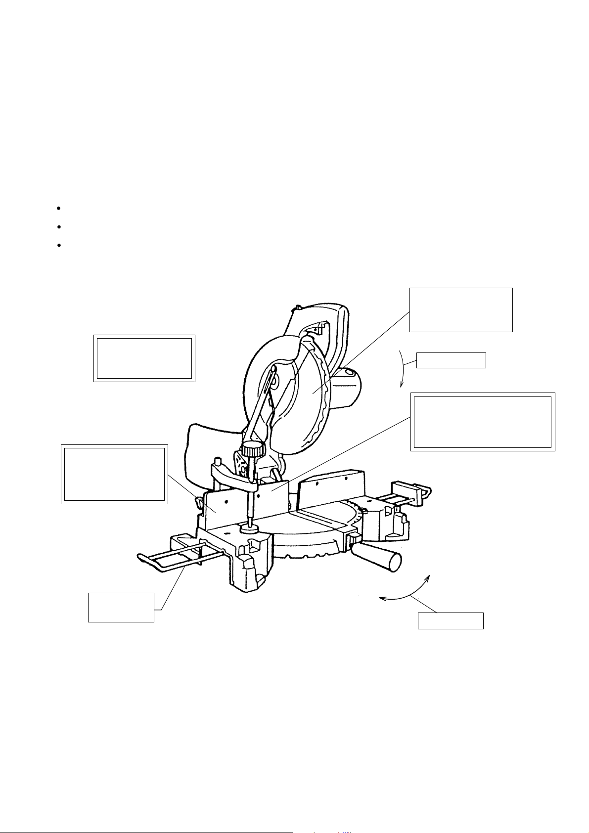
4. SELLING POINTS
24T TCT blade cuts
2 x 6 at 90˚ miter
(4)
2 x 4 at 45˚ miter
Lightweight
27.3 lbs. (12.4 kg)
for easy portability
3-1/8" extra-tall high
fence allows crown
moldings to be cut
standing vertically
Holder ass'y
optional
Left
(1)
Press cutting
(3)
Equipped with a debris
guard to restrict dispersion
of chips for enhanced safety
in operation
Right
(2)
Miter cutting
(Note) Numerals in ( ) are identical with item numbers in "4-1. Selling Point Descriptions".
--- 1 ---
Page 4
4-1. Selling Point Descriptions
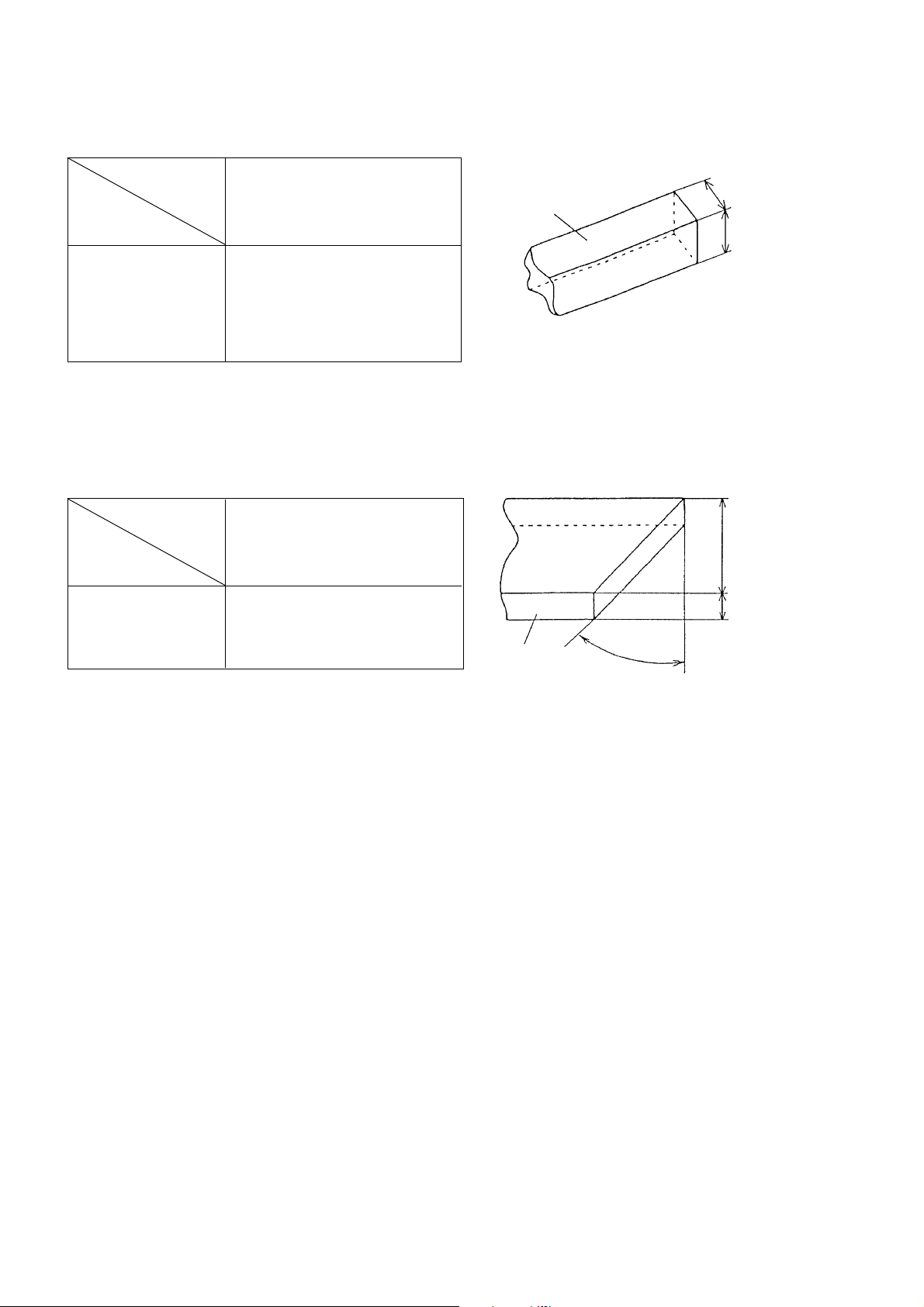
(1) Press cutting
Table 1
Maker
Model
Max. cutting
dimension
66 x 144 (2-19/32" x 5-11/16")
Height x Width
(H x W)
Press cutting with the head swiveling enables cutting square workpieces as large as shown in Table 1 in a single
sawing operation. (See Fig. 1.)
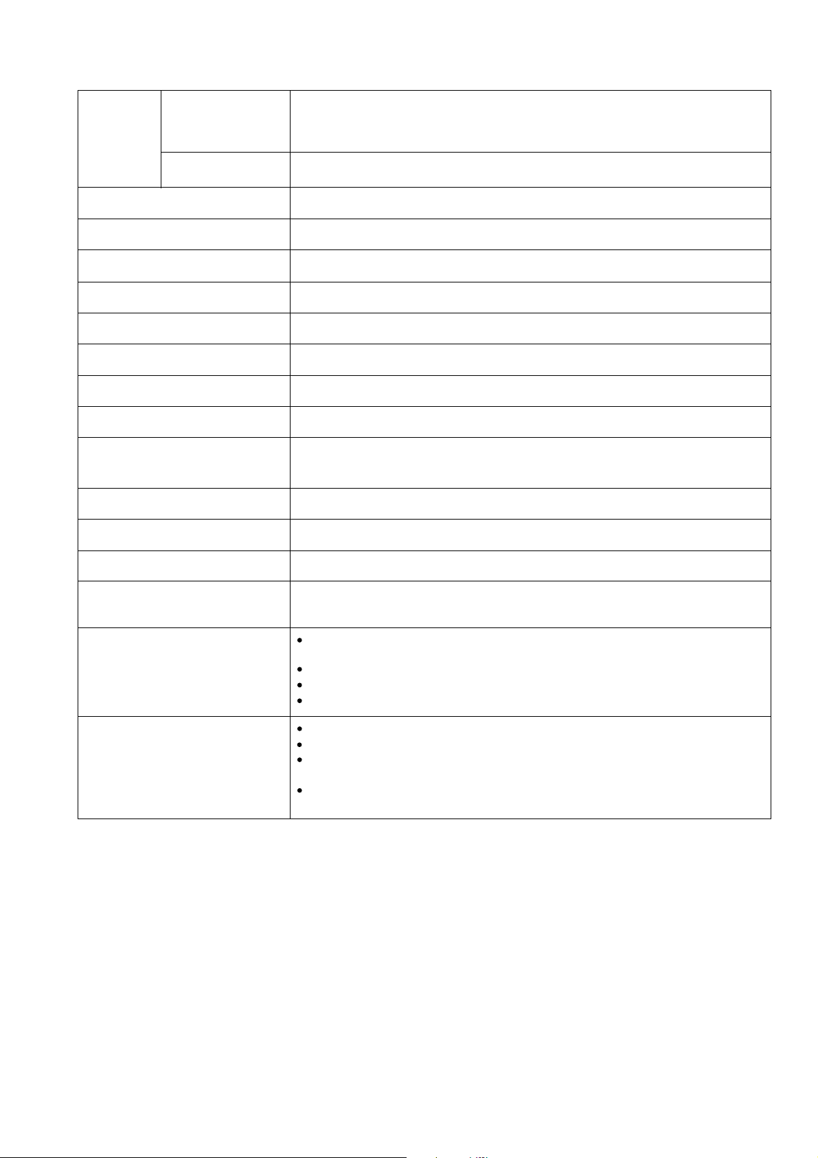
(2) Miter cutting facility
Maker
Model
Max. cutting
dimension
79 x 108 (3-1/8" x 4-1/4")
90 x 90 (3-9/16" x 3-9/16")
with aux. board width
19 mm (3/4")
Table 2
HITACHI
C 10FM
HITACHI
C 10FM
(Unit: mm)
(Unit: mm)
Workpiece
Width (W)
Height (H)
Fig. 1
Width (W)
Right and left 45˚
Height x Width
(H x W)
By turning the table to the right or left as desired, the Model C 10FM is capable of miter cutting of up to 45˚ to the
right and left.
(3) Equipped with debris guard to restrict dispersion of chips for enhanced safety in operation.
A debris guard has been adopted to prevent wood chips from adhering to the saw blade at the end of the
cutting operation.
(4) Lightweight design
12.4 kg in weight, for easy transport in a workshop
68 x 98
(2-11/16" x 3-7/8")
Workpiece
45˚ right and
left
Fig. 2
Height (H)
--- 2 ---
Page 5
5. SPECIFICATIONS
Maximum
cutting
0˚ (Right angle)
dimentions
Height x
Width
(H x W)
Miter right/left 45˚
Miter cutting ranges
Angle stopper positions
Applicable saw blade
Power source type and voltage
Type of motor
Full-load current
No-load rotation speed
Max. output
Main body dimensions
(Width x Depth x Height)
66 mm (2-19/32") x 144 mm (5-11/16")
79 mm (3-1/8") x 108 mm (4-1/4")
90 mm (3-9/16") x 90 mm (3-9/16") [with aux. board width 19 mm (3/4")]
67 mm (2-5/8") x 98 mm (3-7/8")
Right and left 0˚ --- 45˚
Right and left 0˚, 15˚, 22.5˚, 31.6˚ and 45˚
255 mm (10") external dia. x 15.9 mm (5/8") bore
AC single phase 60 Hz, 115 V
AC single phase commutator series motor
13 A (115 V)
4,500/min.
1,600 W
510 mm x 810 mm x 575 mm
(20-3/32" x 31-29/32" x 22-21/32")
Weight
Coating
Packaging
Cord
Standard accessories
Optional accessories
12.4 kg (27.3 Ibs.), gross weight 16.5 kg (36.4 Ibs.)
Metallic silver green
Corrugated cardboard box
Type: 2-Conductor cabtire cable Nominal cross-sectional area: 16AWG (1.25 mm2)
Length: 2.2 m (7.3 ft) External dia.: 7.5 mm with mold plug
255 mm (10") TCT saw blade (24 teeth, Code No. 311128)
•••••••••••••••
for wood and aluminum cutting
Dust bag
Vise ass'y
12.7 mm wrench
Holder ass'y (Code No. 317542)
Vise ass'y (Code No. 317541)
255 mm (10") TCT saw blade (70 teeth, Code No. 976473)
•••••••••••••••
for normal cutting
255 mm (10") TCT saw blade (60 teeth, Code No. 976472)
•••••••••••••••
for fine surface cutting
--- 3 ---
Page 6
6. COMPARISONS WITH SIMILAR PRODUCTS
Maker/Model
Item
Max.
cutting
dimensions
Height
x Width
(H x W)
Miter cutting ranges
Angle stopper position
Saw blade outer diameter (mm)
Full-load current (A)
No-load revolution (/min.)
Motor
Max. output (W)
Insulation structure
Base size
Width x Depth (mm)
Debris guard
Dust bag size (mm)
Main unit dimensions
Width x Depth x Height (mm)
Product weight (kg)
Standard equipment *
Optional accessories
0˚ (Right angle)
Miter right/left 45˚
Right and left 0˚, 15˚, 22.5˚,
31.6˚ and 45˚
(20-3/32" x 31-29/32" x 22-21/32")
• 255 mm (10") TCT saw blade
(24 teeth) for wood and
aluminum cutting
• Dust bag
• Vise ass'y
• 12.7 mm (1/2") wrench
• Holder ass'y
• Vise ass'y
• 255 mm (10") TCT saw blade
(70 teeth) for normal cutting
• 255 mm (10") TCT saw blade
(60 teeth) for fine surface
cutting
HITACHI
C 10FM
66 mm x 144 mm
(2-19/32" x 5-11/16")
79 mm x 108 mm
(3-1/8" x 4-1/4")
90 mm x 90 mm
(3-9/16" x 3-9/16")
[With aux. board width
19 mm (3/4")]
67 mm x 98 mm
(2-5/8" x 3-7/8")
Right and left 0˚--- 45˚
255 (10")
13 (115 V)
4,500
1,600
Double insulation
500 x 120
(19-21/32" x 4-23/32")
Equipped
260 x 180
(10-7/32" x 7")
510 x 810 x 575
12.4 (27.3 lbs.)
*: Standard equipment may differ country to country.
ZC
63 mm x 131 mm
(2-1/2" x 5-5/32")
95 mm x 95 mm
(3-3/4" x 3-3/4")
63 mm x 91 mm
(2-1/2" x 3-19/32")
71 mm x 89 mm
(2-13/16" x 3-1/2")
Right and left 0˚--- 45˚
Right and left 0˚, 22.5˚ and 45˚
254 (10")
13 (120 V)
5,200
-----
Double insulation
450 x 105
(17-23/32" x 4-1/8")
Non
240 x 180
(9-7/16" x 7")
450 x 815 x 500
(17-23/32" x 32-3/32" x 19-21/32")
12.7 (28 lbs.)
• 255 mm (10") cross cut saw
blade (104 teeth)
• Dust bag
• Wrench
• 255 mm (10") TCT saw
blade (60 teeth)
• 255 mm (10") TCT saw
blade (80 teeth)
• Work clamp
70 mm x 119 mm
(2-3/4" x 4-11/16")
89 mm x 89 mm
(3-1/2" x 3-1/2")
70 mm x 84 mm
(2-3/4" x 3-5/16")
89 mm x 59 mm
(3-1/2" x 2-5/16")
Right 0˚--- 52˚
Left 0˚--- 45˚
Right and left 0˚, 15˚, 22.5˚, 30˚
and 45˚
255 (10")
12 (115 V)
4,600
-----
Double insulation
460 x 100
(18-3/32" x 3-15/16")
Non
190 x 205
(7-15/32" x 8-1/16")
460 x 750 x 505
(18-3/32" x 29-17/32" x 19-27/32")
12.6 (27.8 lbs.)
• 255 mm (10") cross cut saw
blade
• Dust bag
• 13 mm socket wrench
• Triangular rule
• Safety goggles
• 255 mm (10") TCT saw blade
(50 teeth) for wood
• 255 mm (10") miter saw blade
(100 teeth) for wood
• 255 mm (10") miter saw blade
(100 teeth) for aluminum
• 255 mm (10") cross cut saw
blade (50 teeth) for wood
• 255 mm (10") combination
saw blade (36 teeth) for wood
• Holder
• Vertical vise
--- 4 ---
Page 7
7. PRECAUTIONS IN SALES PROMOTION
In the interest of promoting the safest and most efficient use of the Model C 10FM Miter Saw by all of our
customers, it is very important that at the time of sale the salesperson carefully ensures that the buyer seriously
recognizes the importance of the contents of the Instruction Manual, and fully understands the meaning of the
precautions listed on the various Caution Plates attached to each machine.
7-1. Instruction Manual
Although every effort is made in each step of design, manufacture and inspection to provide protection against
safety hazards, the dangers inherent in the use of any power saw cannot be completely eliminated. Accordingly,
general precautions and suggestions for the use of electric power tools, and specific precautions and suggestions
for the use of the compound saw are listed in the Instruction Manual to enhance the safe, efficient use of the tool
by the customer. Salespersons must be thoroughly familiar with the contents of the Instruction Manual to be able
to offer appropriate guidance to the customer during sales promotion.
(1) Precautions on the Name Plate
Each Model C 10FM is furnished with a Name Plate that lists the following precautions.
Instruct the customer to thoroughly read the Instruction Manual prior to attempting to operate the machine.
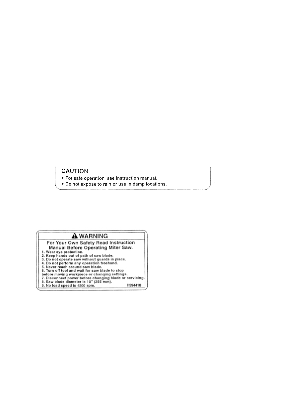
(2) Warning Label (A)
The Warning Label (A) specified by the UL is affixed
on the upper righthand portion of the motor housing.
Please instruct users to strictly observe the contents
in 1 to 9 in the Warning Label (A) shown at left.
--- 5 ---
Page 8
8. ADJUSTMENT AND OPERATIONAL PRECAUTIONS
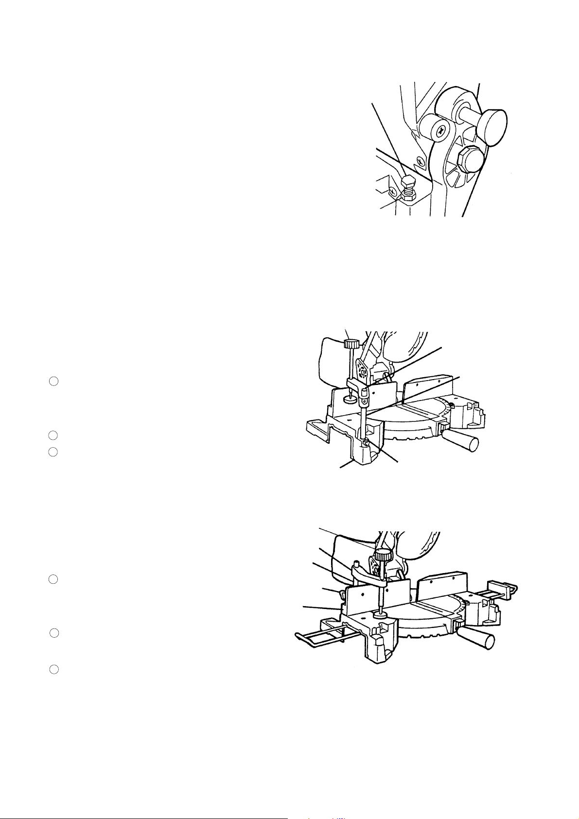
8-1. Confirmation of Saw Blade Lower Limit Positioning
The lower limit of the saw blade cutting depth is factory-adjusted
M6 x 20 mm
hex. hd. bolt
so that when the saw blade is fully lowered, its cutting edge is
28 mm to 30 mm (1-3/32" to 1-5/32") below the upper surface of
the table insert. Lower the saw blade and confirm that it stops at
the correct position.
If it is necessary to adjust the saw blade lower limit, loosen the
6 mm hex. nut on the M6 x 20 mm hex. hd. bolt, and turn the
6 mm hex. nut
M6 x 20 mm hex. hd. bolt if necessary. (See Fig. 3.)
Fig. 3
[CAUTION] Perform the adjustment carefully to ensure that the saw blade does not cut into the table. Also,
on completion of adjustment, ensure without fail that the 6 mm hex. nut is securely tightened.
8-2. How to Use the Vise Ass'y
(1) The vise ass'y can be mounted on either the left side
base or the right side base, and can be raised or
Knob
Vise
assembly
lowered according to the height of the workpiece.
1
Insert the support of the vise ass'y into the hole
Support
located on either the left side base or the right side
base.
2
Then tighten the 5 mm clamp bolt, as shown in Fig. 4.
3
Turn the knob to thoroughly clamp the workpiece.
[NOTE] The support has two locking grooves into which
the tip of the 5 mm clamp bolt is designed to fit,
to lock the vise ass'y in the desired position.
(2) The vise ass'y can be mounted on either the left side
fence or the right side fence, and can be raised or
lowered according to the height of the workpiece.
Insert the support of the vise ass'y into the hole
1
located on either the left side fence or the right
side fence.
2
Then tighten the 5 mm clamp bolt, as shown in
Fig. 5.
3
Turn the knob to thoroughly clamp the workpiece.
Vise
assembly
Support
5 mm
clamp bolt
Fence
Base
Knob
5 mm
clamp bolt
Fig. 4
Fig. 5
[Warning] Always firmly clamp or vise to secure the workpiece to the fence; otherwise the workpiece
might be thrust from the table and cause bodily harm.
--- 6 ---
Page 9

8-3. Cutting Operation
(1) Cutting efficiency will be reduced if a dull saw blade is used, if an excessively long extension cord is used, or if
the wire gauge of the extension cord is too small. (For details on extension cords, please refer to the
Instruction Manual.) This is particularly important when cutting materials with dimensions which are at or near
the maximum capacity for the machine.
(2) The customer should be advised to thoroughly inspect the workpiece to ensure that there are no metallic
objects (nails in particular), sand, or other foreign matter in or on the workpiece. Saw blade contact with such
foreign matter will not only shorten the service life of the saw blade, but could cause serious accident. Should
the saw blade tips be broken off, the tips may fly toward the operator.
(3) Press cutting
Like Mode C 10FC2, C 10FM can be used for press cutting of workpieces up to 66 mm x 144 mm (2-19/32" x
5-11/16") in a single operation by simply pushing the saw blade section (head) downward. The customer
should be cautioned that excessive pressure on the handle will not increase the cutting speed. On the
contrary, excessive pressure may result in reduced cutting efficiency (irregular or rough cutting of the
workpiece), and could also cause overload and subsequent burnout of the motor.
On completion of the cutting operation, turn the switch OFF and wait for the saw blade to come to a complete
stop before raising the saw blade section (head) to its original position. Raising the saw blade section (head)
while the saw blade is rotating may cause unwanted cutting marks on the workpiece.
Techniques to avoid unwanted cutting marks
Uneven and unwanted cutting marks can be avoided throughout the cutting operation by gently and smoothly
pressing down on the handle, so that the entire cutting operation is accomplished in a single uninterrupted
motion.
(4) Miter cutting
Miter cutting is accomplished by turning the table. (For details, please refer to the Instruction Manual.)
--- 7 ---
Page 10
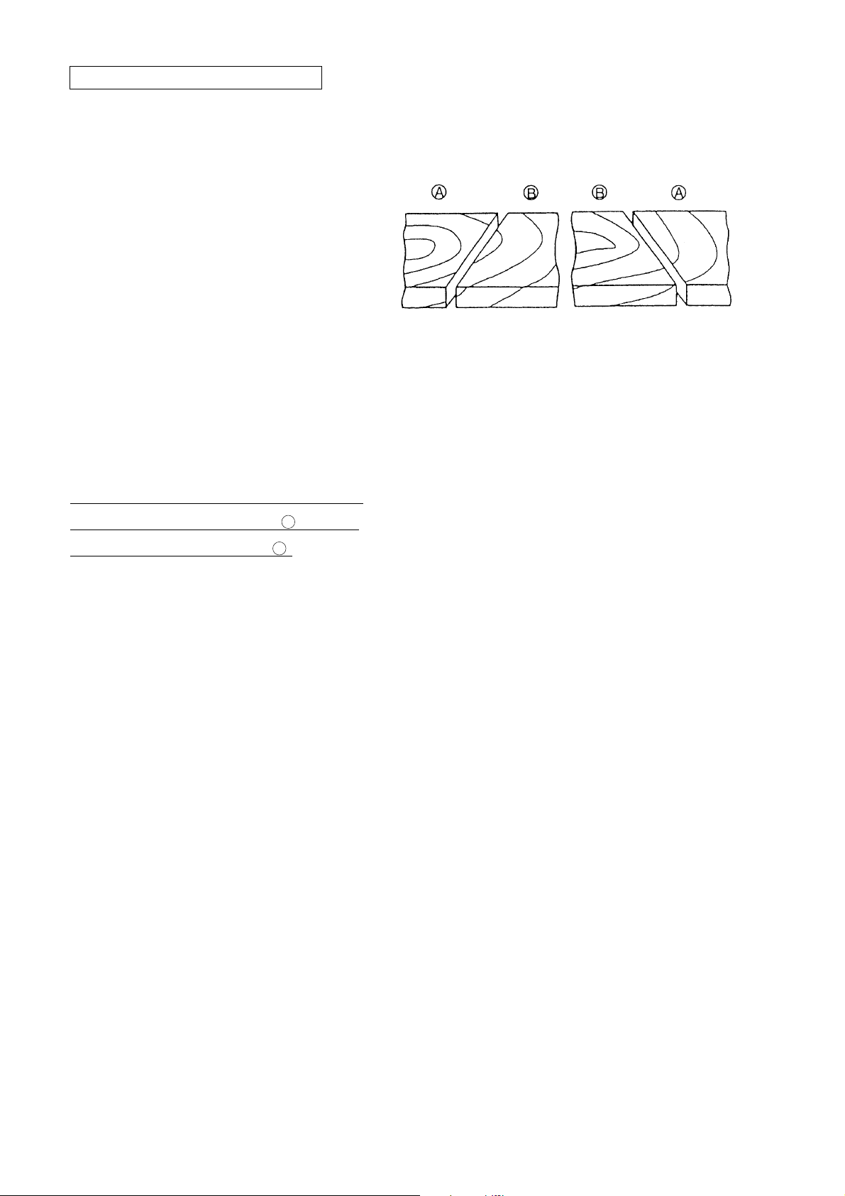
(5) Cut surface quality during miter cutting
The quality of the cut surface depends on the
type of cutting operation (miter), the type and
sharpness of the saw blade, whether the
workpiece is cut to the right or left. In miter
cutting in particular, cutting is performed across
the wood grain, so the condition of the cut
surface depends on whether the wood is cut
with or against the grain. This is the same as
when using electric portable planers.
Customers should be advised of these
phenomena so that they understand that in
cases when the cut surface may not be as
smooth as expected or hoped for, it is not
caused by the performance of the saw blade or
the Model C 10FM.
In the cutting examples illustrated in Fig. 6, the
cut surfaces on the sides marked are better
than those on the sides marked .
A
B
[Miter cutting]
Better Better
Fig. 6
9. PACKING
The main body of the Model C 10 FM is sandwiched between packing (A) and packing (B) made of styrofoam.
This system makes the packaging work easier.
(1) Preparation
Remove the vise ass'y and dust bag from the main unit.
Then swivel the table through 45˚ toward the right.
Fix the table securely with the miter handle.
Push down the head section and insert the locking pin to secure the head section at the lower position.
(2) How to install packing (A)
Put packing (A) in the carton box.
Put the main unit in packing (A).
(3) How to install packing (B)
Put packing (B) on the main unit. Put the vise ass'y and the dust bag in the groove of packing (B).
Close the lids of the carton box and bind them together.
--- 8 ---
Page 11

10. PRECAUTIONS IN DISASSEMBLY AND REASSEMBLY
Please follow the precautions below for disassembly and reassembly procedures. The circled numbers in the
following figures and the [Bold] numbers in the descriptions below correspond to the item numbers in the Parts
List and exploded assembly diagrams.
CAUTION: Prior to attempting disassembly or replacement of the saw blade, ensure that the power cord
plug is disconnected from the power source.
10-1. Disassembly
A. Disassembly of the blade guard section
Tools required:
• Phillips head screwdriver
• 12.7 mm wrench (standard accessory)
• 10 mm wrench
Fig. 7
1. Loosen the Counter Hd. Screw M5 x 12 [25] and turn the Cutter Shaft Guard [26] upward so that the Bolt (Left
Hand) W/Washer M8 x 20 [51] can be seen.
2. Put the Wrench [702] on the Bolt (Left Hand) W/Washer M8 x 20 [51] and turn the Wrench [702] until the
Bracket Stop [88] is aligned with the groove of the Arbor Shaft [76] while pushing the Bracket Stop [88].
Then loosen the Bolt (Left Hand) W/Washer M8 x 20 [51] and remove the Bolt (Left Hand) W/Washer M8 x 20
[51], outside Arbor Collar [52], TCT Saw Blade [701], inside Arbor Collar [52].
3. Put the Cutter Shaft Guard [26] back into position and tighten the Counter Hd. Screw M5 x 12 [25].
--- 9 ---
Page 12

4. Remove the Truss Hd. Step Screw M6 x 12 [14] and the Truss Hd. Step Screw M6 x 14 [15] that fix the Lever
[16]. Remove the Lever [16].
5. Secure the Special Nut Chuck M6 [27] behind the Cutter Shaft Guard [26] with a 10 mm wrench. Remove the
Counter Hd. Screw M6 x 16 [18], Collar [19], PC-Guard [20], Hex. Nut M6 [23] and Spring Guard [24].
B. Disassembly of the base section
Tools required:
• 3 mm hex. bar wrench
• Phillips head screwdriver
• 19 mm wrench
• Plastic hammer
• D10 metal bar
• 6 mm hex. bar wrench
• 10 mm wrench
• 13 mm box wrench
Fig. 8
--- 10 ---
Page 13

1. Remove the Hex. Socket Hd. Bolt M6 x 12 [33], and take out the Anchor Block [32]. As the Hex. Socket Hd.
Bolt M6 x 12 [33] acts as a stopper for the Upper Arm [86], be very careful to prevent the Upper Arm [86] from
springing up suddenly when the Hex. Socket Hd. Bolt M6 x 12 [33] is removed.
2. Remove the two Special Screws M4 x 8 [50] and the Chip Plate [49].
3. Remove the Nut Chuck [41] by turning it with a 19 mm wrench.
4. Remove the two Hex. Socket Set Screws M6 x 10 [31] behind the Upper Arm [86] with a 3 mm hex. bar
wrench.
5. Pull out the Shaft [36] by gently tapping it while holding the Upper Arm [86].
6. Removing the Shaft [36] enables you to remove the Torsion Spring [48] and the Shaft Sleeve [47].
7. Separate the Motor Ass'y [35] from the Support [39].
8. Remove the two Special Screws M5 x 16 [46] and the Chip Deflector [45] (debris guard).
9. Remove the four Special Screws M4 x 10 [65] and the Table Insert [66].
10. Remove the two Hex. Socket Hd. Bolts M8 x 45 [54] with a 6 mm hex. bar wrench. Remove the Fence [55].
11. Turn the Handle Ass'y [71] counterclockwise and remove it .
12. Then, turn the Base [59]. (Base [59] surface upside down.)
13. Remove the three Hex. Socket Hd. Bolts M8 x 25 [63] with a 6 mm hex. bar wrench. Remove the Support
[39].
14. Remove the two Hex. Bolts (W/Washer) M6 x 20 [69] with a 10 mm wrench to remove the Spring Plate [70].
15. Remove the Hex. Bolt (W/Washers) M6 x 20 [68] with a 10 mm wrench. Remove the Washer [67].
16. Then, turn the Base [59]. (Base [59] surface upside down.)
17. With a 13 mm box wrench, remove the Nut Chuck M8 [60] and the Flat Washer M8 [61] from the insert space
of the Table [64]. Extract the Center Shaft [74] which fixes the Table [64] to the Base [59] by lifting the Table
[64] upward.
--- 11 ---
Page 14

C. Disassembly of the motor section
Tools required:
• Flatblade screwdriver
• Phillips screwdriver
• Plastic hammer
• Nipper
Fig. 9
1. Remove the two Brush Caps [100] to remove two Carbon Brushes [99].
2. Remove the four Tapping Screws (W/Sp. Washer) D5 x 16 [96]. Remove the Motor Housing [95] with the
Armature Ass'y 115 V [89] and the Field [93] mounted.
--- 12 ---
Page 15

(1) Disassembly of the armature ass'y
1
Tap the Upper Arm [86] mounting surface of the Motor Housing [95] with a plastic hammer and remove the
Armature Ass'y 115 V [89].
2
Remove the Flow Guide [92].
3
Remove the six Tapping Screws D4 x 20 [9] and the Handle Cover [4].
4
Remove the Spring [7] and the Switch [8].
5
Remove the Truss Hd. Tapping Screw D4 x 12 [5] and the Switch [6].
Disconnect the three internal wires from the Switch [6].
6
7
Remove the two Truss Hd. Tapping Screws D4 x 12 [3] and the Cord Clamp [2].
(2) Disassembly of the field
1
Disconnect the Internal Wire [90] from the Brush Holder [98] and disconnect the internal wire from the Field
[93].
2
Cut the white internal wires coming from the Power Cable [13] and the Field [93] and connected with the
Terminal [12] with a nipper.
3
Remove the two Tapping Screws (W/SP. Washer) D5 x 60 [94] that fix the Field [93]. By tapping the Upper
Arm [86] mounting surface of the Motor Housing [95] with a plastic hammer, pull out the Field [93].
(3) Disassembly of the Spindle Ass'y
1
Remove the three Tapping Screws M4 x 16 [28] and the Housing [29].
2
Remove the three Machine Screws (W/Flange) M5 x 10 [78] and the Bearing Cover [79].
3
Remove the Spindle Ass'y [116] by gently tapping the Upper Arm [86] with a plastic hammer.
--- 13 ---
Page 16

D. Disassembly of the bracket stop
Tools required:
• Pliers
Fig. 10
1. Remove the Spring Pin [87] from the Bracket Stop [88].
2. Remove the Bracket Stop [88] and the Compression Spring [85] from the Upper Arm [86].
E. Disassembly of the vise ass'y
Tools required:
• 3 mm hex. bar wrench
Fig. 11
1. Remove the Hex. Socket Set Screw M6 x 10 [108] and the Support [109].
--- 14 ---
Page 17

10-2. Reassembly
Reassembly can be accomplished by following the disassembly procedures in reverse. However, special
attention should be given to following items.
(1) Prior to reassembly, measure the insulation resistance of the armature, field, switch and other electrical
components and confirm that the insulation resistance of each part is more than 7 M Ω.
(2) When assembling the Support [39] and the Upper Arm [86], apply 2 grams (2 pcs.) of Hitachi Motor Grease to
the oil groove of the Upper Arm [86].
(3) When replacing the Torsion Spring [48], apply approximately 5 grams of Hitachi Motor Grease to the inner
circumference of the new Torsion Spring [48] prior to reaasembly.
(4) When replacing the Slide Plate [75], assemble it into the unit as illustrated in Fig. 12. During reassembly,
apply 6 grams of Hitachi Motor Grease to the Slide Plate [75] against the sliding surface of the Base [59].
Ensure that the Slide Plate [75] fits into
the groove portion of the Base [59].
Fig. 12
(5) If the Center Shaft [74] at the bottom of the Base [59] is tightened excessively, the movement of the Table [64]
will become sluggish and heavy. If the bolt is loose, it will cause vibration and looseness of the Table [64]
which will reduce cutting accuracy. Adjust the Nut Chuck M8 [60] so that the Table [64] moves smoothly with
minimum play and vibration.
--- 15 ---
Page 18

10-3. Wiring Diagram
Carefully ensure that wiring is accomplished as illustrated below. As incorrect wiring will result in lack of rotation,
reverse rotation or other malfunctions, close attention is absolutely necessary.
1
Wiring diagram
Red
Switch
1a
Black
Power cable
Armature
ass'y
2
Actual wiring diagram
Switch
1
Brake coil
Field coil
Field
Power cable
Black
1
Gray
White
White
Fig. 13
1
1b
White
Terminal
Terminal
White
1b
1a
Red (Lead wire)
Gray
Field
Brush holder
Red
Fig. 14
10-4. Lead Wire Precautions
When connecting lead wires be very careful not to remove the insulation covering of each lead wire more than
needed. Exposed cores of lead wires from connectors, for example, are extremely dangerous. Also, ensure that
the lead wires are not pinched between the mating surfaces of the Motor Housing [95] and the Handle Cover [4].
--- 16 ---
Page 19

10-5. No-load Current
After no-load operation for 30 minutes, the no-load current values should be as follows.
Voltage, frequency
No-load current
115 V, 60 Hz
6.3 A max.
10-6. Reassembly Requiring Adjustment
(1) Adjustment of squareness between the saw blade (dummy disc) and the fence
After disassembly/reassembly or replacement of the Base [59], the
Table [64], the Fence [55] or the Support [39], it is necessary to
check the squareness between the saw blade (or dummy disc) and
Fence
Square
Saw blade or
dummy disc
Fig. 15
the Fence [55], and perform adjustment as necessary if they are not
at an exact right angle with relation to each other. Adjustment
procedure is as follows. First, position the saw blade (or dummy
disc) so that it is in the exact center of the groove on the Table [64]
which houses the Table Insert [66]. Next, as illustrated in Fig. 15,
place a square so that it is flush against the side surface of the saw blade (or dummy disc), and move the
Fence [55] as necessary so that it is in an exact right angle with relation to the saw blade (or dummy disc).
Finally, tighten the two Hex. Socket Hd. Bolts M8 x 45 [54] to fix the Fence [55] in position.
*Dummy disc: A dummy disc is a toothless disc with the same external diameter as a saw blade, and is used
to perform accurate inspection and adjustments.
(2) Confirmation of saw blade height
The lower limit of the saw blade cutting depth is factory-adjusted so that when the saw blade is fully lowered,
its cutting edge is 28 to 30 mm (1-3/32" to 1-5/32") below the upper surface of the Table Insert [66]. Lower the
saw blade and confirm that it stops at the correct position.
(3) Adjustment of saw blade lower limit position
When adjusting the lower limit of the saw blade, be sure to use a saw blade with an external diameter of 255
mm. Failure to properly adjust the lower limit position of the saw blade may result in the following problems.
1
Inability to obtain the maximum cutting capacities of the machine
2
There is a danger that the saw blade may come in contact with and cut into the Table [64].
The lower limit of the saw blade cutting depth is adjusted at the factory so that when the saw blade is fully
lowered, its cutting edge is 28 mm to 30 mm (1-3/32" to 1-5/32") below the upper surface of the Table Insert
[66]. If this position is lower than the specified values, confirm without fail that it does not come in contact with
the Table [64]. If it is necessary to adjust the saw blade lower limit, loosen the Hex. Nut M6 [38] on the Hex.
Bolt M6 x 20 [37] and turn the Hex. Bolt M6 x 20 [37] if necessary. By turning the Hex. Bolt M6 x 20 [37]
clockwise, the saw blade lower limit is lowered. By turning the Hex. Bolt M6 x 20 [37] counterclockwise, the
saw blade lower limit is raised. On completion of adjustment, ensure that the Hex. Nut M6 [38] is properly
tightened.
[Caution]
Perform the adjustment carefully to ensure that the saw blade does not cut into the Table [64].
--- 17 ---
Page 20

(4) Reassembly of the Table [64]
When reassembling the Table [64] and the Base [59], tighten the Nut Chuck M8 [60] so that the Table [64]
turns smoothly without excessive play or vibration.
During reassembly, liberally apply grease (Hitachi Motor Grease No. 29, Code No. 930035 is recommended.)
at the point marked A in Fig. 16.
Nut Chuck M8 [60]
Table [64]
A
A
Base [59]
Center Shaft [74]
Fig. 16
10-7. Lubrication
Advise the customer to lubricate the machine as indicated below at least once a month. Also, prior to applying
lubrication, any sawdust, dirt or other foreign matter should be thoroughly wiped away with a soft cloth.
(1) Swiveling section of the Upper Arm [86] and the Support [39]
Coat the swiveling portion of the Upper Arm [86] and the Support [39] with machine oil.
(2) Vise ass'y section
Coat the screw threads portion of the Screw Bar [110] of the Vise Ass'y [107] with machine oil.
10-8. Product Precision
On completion of reassembly, confirm precision tolerances.
(Unit: mm)
Item Tolerance
Run-out of saw blade (or dummy disc) 0.38/220 (0.015"/8-21/32")
Perpendicularity between base and fence 0.4/100 (0.016"/4")
Perpendicularity between saw blade (or dummy disc) and fence 0.4/100 (0.016"/4")
Perpendicularity between saw blade (or dummy disc) and table 0.4/100 (0.016"/4")
Surface alignment of
+ +
base and table (Use
the upper surface of
0.45 ( 0.018")
--
--
0.1 ( 0.004")
the base as a
reference).
--- 18 ---
Page 21

10-9. Tightening Torque
• D4 x 12 Truss Hd. Tapping Screw
• D4 x 20 Pan Hd. Tapping Screw
• M4 x 20 Pan Hd. Screw
••••••••••••••••••••••••••••••••••••
• D6 x 10 Pan Hd. Tapping Screw
• M6 x 14 Truss Hd. Round Neck Screw
• M6 x 16 Count Hd. Screw
• M5 x 12 Count Hd. Screw
••••••••••••••••••••••••••••••••
• D4 x 16 Pan Hd. Tapping Screw
• M6 x 10 Hex. Socket Set Screw
• M6 x 12 Hex. Socket Hd. Cap Bolt
• M6 x 20 Hex. Hd. Bolt
• M5 x 16 Pan Hd. Screw
• M4 x 8 Pan Hd. Screw
•••••••••••••••••••••••••••••••••••••••
••••••••••••••••••••••••••••••••••••
••••••••••••••••••••••••••••••••••••••
• M8 x 20 Hex. Washer Hd. Bolt
• M8 x 45 Hex. Socket Hd. Bolt
• D4 x 8 Pan Hd. Tapping Screw
• M8 x 25 Hex. Socket Hd. Cap Bolt
• M4 x 10 Pan Hd. Screw
•••••••••••••••••••••••••••••••••••••
• M6 x 20 Hex. Hd. Bolt (W/Washers)
• M5 x 12 Pan Hd. Screw
••••••••••••••••••••••••••••••••••••
• M5 x 10 Round Hd. Washer Screw
• D5 x 60 Pan Tapping Screw & Washer
•••••••••••••••••••••
••••••••••••••••••••••
••••••••••••••••••••••••
••••••••••••••
•••••••••••••••••••••••••••••••
••••••••••••••••••••••••
••••••••••••••••••••••••
••••••••••••••••••••
•••••••••••••••••••••••••••
•••••••••••••••••••••••••
••••••••••••••••••••••••••
•••••••••••••••••••••
•••••••••••••••••
•••••••••••••••••••
••••••••••••••
• D5 x 35 Pan Hd. Tapping Screw & Washer
• M5 x 8 Hex. Socket Set Screw
•••••••••••••••••••••••••••
••••••••••
13 in-lbs. (1.5 N•m, 15 kgf•cm)
6.9 in-lbs. (0.8 N•m, 8 kgf•cm)
6.9 in-lbs. (0.8 N•m, 8 kgf•cm)
15.6 in-lbs. (1.8 N•m, 18 kgf•cm)
15.6 in-lbs. (1.8 N•m, 18 kgf•cm)
30.4 in-lbs. (3.4 N•m, 35 kgf•cm)
8.7 in-lbs. (1 N•m, 10 kgf•cm)
6.9 in-lbs. (0.8 N•m, 8 kgf•cm)
34.7 in-lbs. (3.9 N•m, 40 kgf•cm)
26 in-lbs. (2.9 N•m, 30 kgf•cm)
30.4 in-lbs. (3.4 N•m, 35 kgf•cm)
4.3 in-lbs. (0.5 N•m, 5 kgf•cm)
4.3 in-lbs. (0.5 N•m, 5 kgf•cm)
130 -- 156 in-lbs. (14.7 -- 17.6 N•m, 150 -- 180 kgf•cm)
47.7 in-lbs. (5.4 N•m, 55 kgf•cm)
15.6 in-lbs. (1.8 N•m, 18 kgf•cm)
10.4 in-lbs. (1.2 N•m, 12 kgf•cm)
8.7 in-lbs. (1 N•m, 10 kgf•cm)
52 in-lbs. (5.9 N•m, 60 kgf•cm)
8.7 in-lbs. (1 N•m, 10 kgf•cm)
34.7 in-lbs. (3.9 N•m, 40 kgf•cm)
21.7 in-lbs. (2.5 N•m, 25 kgf•cm)
22.6 in-lbs. (2.5 N•m, 26 kgf•cm)
6.9 in-lbs. (0.8 N•m, 8 kgf•cm)
--- 19 ---
Page 22

11. REPAIR GUIDE
Item Phenomenon Cause (s)
Factory
standard
Unit: mm
Inspection • Repair •
Adjustment
Inaccurate cutting
1
•••
Inaccurate
squareness of cut
surface
•••
Cut surfaces do not
fit together properly.
Fence
Table
Fig. 17
Squareness
0.4/100
(1/64"/3-15/16")
Fig. 18
Saw blade
Squareness
0.4/100
(1/64"/3-15/16")
Saw blade
Fence
a Inaccurate
squareness between
the table and the saw
blade causes the saw
blade to cut into
workpiece at an angle.
b Excessive deflection
of the saw blade
(Excessive vibration)
c Inaccurate
squareness between
the fence and the saw
blade
d Inaccurate surface
flatness of the fence
causes workpiece to
move irregularly,
causing poor
squareness of cut
surface.
0.4/100
(1/64"/3-15/16")
(Dummy disc)
(Fig. 17)
0.38/220
(0.015"/8-21/32")
(Dummy disc)
0.4/100
(1/64"/3-15/16")
(Fig. 18)
Within 0.15
(0.06")
(Fig. 19)
• Replace the Upper Arm
[86], Table [64] and/or the
Support [39]. (If deformed.)
• Replace the TCT Saw Blade
[701].
• Check for surface defects on
the Arbor Collar [52], and
repair with a file as
necessary.
• Replace the Arbor Collar
[52] as necessary.
• Loosen the Hex. Socket Hd.
Bolt M8 x 45 [54] and adjust
as necessary.
• Replace the Fence [55] as
necessary.
• Replace the Fence [55] as
necessary.
Within 0.15 (0.06") or less
Fig. 19
0.4/100
(1/64"/3-15/16")
Squareness
Fig. 20
Within 0.15 (0.06")
Fence
Fence
e Inaccurate surface
flatness of the table
f Inaccurate
squareness between
the fence and the
table and/or the base
causes the workpiece
to tilt at an angle and
prevent accurate
cutting.
Within 0.1
(0.004")
0.4/100
(1/64"/3-15/16")
(Fig. 20)
• Replace the Table [64].
• Replace the Fence [55] as
necessary.
--- 20 ---
Page 23

Item
Phenomenon
Cause (s)
Factory
standard
Inspection • Repair •
Adjustment
(Continued)
1
Base
Fig. 21
Table
g Excessive
misalignment of the
base and the table
causes the saw blade
to cut into the
workpiece at an angle.
h Loose fitting of
swiveling portion of
the upper arm and the
support or sluggish
movement. As a
result, components
may be deformed
because of unstable
upper arm or because
the operator must
apply excessive
pressure during
operation.
i Excessively fast
cutting speed causes
deflection of the saw
blade and inaccurate
cutting.
+
0.45 (0.018")
--
0.1 (0.004")
(Fig. 21)
------
------
• Replace the Base [59] and/or
Table [64] if deformed.
• Check the fitting surfaces of the
Upper Arm [86], Support [39]
and the Shaft [36] for any
foreign substance (such as
cutting dust), and remove it as
necessary.
• Reduce cutting speed.
Appropriately 10 seconds for a
square wood workpiece of
60 mm (2-3/8").
2 Rough cut surface
Parallelism A = 0.025/54
(0.001/2-1/8")
Arbor collar Arbor collar
Fig. 22
j Excessive cutting
force (pressure) is
required because of
dull saw blade.
k The workpiece moves
during cutting because
it is bent or deformed.
a Large deflection of the
saw blade. (It causes
rough cut surface.)
b Each surface
parallelism of the
arbor collar is
inaccurate due to
surface defects (such
as impact marks and
scratches).
c Inaccurate
squareness between
the table and the saw
blade, causing the
saw blade to cut at an
improper angle and
make cutting marks.
------
------
0.38/220
(0.015"/8-21/32")
(Dummy disc)
0.025/54
(0.001"/2-1/8")
(Fig. 22)
0.4/100
(1/64"/3-15/16")
(Fig. 17)
• Sharpen the TCT Saw Blade
[701] again.
• Correct bend, flex or other
deformation by planing and try
cutting.
• Same as the Item 1- b .
• Repair impact marks or
scratches at the Arbor Collar
[52] or replace it if necessary.
• Same as the Item 1- a .
--- 21 ---
Page 24

Item
Phenomenon
Cause (s)
Factory
standard
Inspection • Repair •
Adjustment
2
(Continued)
3
Saw blade is locked.
d Excessively fast
cutting speed
e Improper clamping of
workpiece
f The table is not fixed
with the handle bar.
g Loose fitting of
swiveling portion of
the upper arm and the
support, or sluggish
movement
h Cutting operation
becomes sluggish
because workpiece is
warped or bent.
i Excessive vibration
a Excessively fast
cutting speed
------
------
------
------
-----
------
------
------
• Reduce cutting speed.
• Properly clamp workpiece with
the vise Ass'y [107].
• During cutting, fix the Table [64]
in position with the Handle
Ass'y [71] without fail.
• Same as the item 1 - h .
• Correct warp or bend with
planer.
• Recheck the items a, b, c, d, f
and g.
• Reduce cutting speed.
b Core diameter of
extension cord is too
small.
c Excessive cutting force
is applied due to dull
saw blade.
d Incorrect saw blade is
used.
e The saw blade binds in
workpiece during
cutting because
workpiece is warped
or bent.
------
------
------
-----
• Use a thicker and shorter
extension cord.
Extension
cord length
25 ft. (7.5 m)
50 ft. (15 m)
100 ft. (30 m)
Wire gauge
size
2.0 mm
3.5 mm
Not
recommended
2
14 A.W.G.
2
12 A.W.G.
• Resharpen the TCT Saw
Blade [701].
• Use a suitable Hitachisupplied saw blade.
• An increased number of teeth
on the saw blade increases
the cutting resistance.
When using a saw blade with
a large number of teeth,
reduce the cutting speed.
• Correct workpiece
deformation with planer.
--- 22 ---
Page 25

Item
Phenomenon
Cause (s)
Factory
standard
Inspection • Repair •
Adjustment
4 Saw blade does not
rotate when switch is
triggered.
Saw blade runs too
5
slow.
(Not within 4050 -- 4950/min.)
a The power cord is not
connected to power
supply.
b The carbon brush
wear exceeds
allowable limit (6 mm).
c Contact failure of the
switch.
a Power supply voltage
is lower than rated
voltage.
------
------
------
------
• Check power supply voltage.
• Connect the power cord to
power supply.
• Check the Carbon Brushes [99]
for wear.
• Replace the Carbon Brushes
[99].
• Check the Switch [6] for
conductivity.
• Replace the Switch [6].
• Check for power supply
voltage.
• Check that extension cord is
appropriate. See the
Instruction Manual for
appropriate extension cords.
--- 23 ---
Page 26

12. STANDARD REPAIR TIME (UNIT) SCHEDULES
MODEL 10 20 30 40
Fixed
Variable
Work Flow
C 10FM
General Assembly
Fixed Cost
Lever
PC-Guard
Handle
Chip Deflector
Power Cable
Switch
Others
0 min.
10 min.
20 min.
Carbon Brush
Lever
PC-Guard
Chip Deflector
Fence
Table Insert
Armature Ass'y
Housing
Compression
Spring
Bracket Stop
Shaft
Torsion Spring
Handle Cover
Cord Guard
Power Cable
Spindle Ass'y
Switch
Field
Motor Housing
Base
Slide Plate
Support
50
60
Table
Spring
Plate
70 min.
Upper
Arm
--- 24 ---
Page 27

Assembly Diagram for C 10FM
--- 25 ---
Page 28

Motor Assembly
Holder Assembly
--- 26 ---
Page 29

Vise Assembly
--- 27 ---
Page 30

PARTS
ITEM
2
CODE NO. DESCRIPTION
No.
1 311-096 CORD GUARD 1
2 311-070 CORD CLAMP 1
3 311-103 TRUSS HD. TAPPING SCREW D4X12 2
4 318-850 HANDLE COVER 1
5 311-103 TRUSS HD. TAPPING SCREW D4X12 1
6 317-553 SWITCH 1
7 311-106 SPRING 1
8 318-851 SWITCH 1
9 317-377 TAPPING SCREW D4X20 6
11 317-070 MACHINE SCREW M5X12 3
12 318-852 TERMINAL 1
13 318-853 POWER CABLE 1
14 314-980 TRUSS HD. STEP SCREW M6X12 1
15 317-496 TRUSS HD. STEP SCREW M6X14 1
16 318-854 LEVER 1
17 317-505 FLAT WASHER M6 1
18 317-582 COUNTER HD. SCREW M6X16 1
19 317-583 COLLAR 1
20 318-855 PC-GUARD 1
21 311-036 RIVET 3/16"X17/32" 1
22 317-585 BUMPER 1
23 318-856 HEX. NUT M6 1
24 314-987 SPRING GUARD 1
25 317-586 COUNTER HD. SCREW M5X12 1
26 318-857 CUTTER SHAFT GUARD 1
27 314-522 SPECIAL NUT CHUCK M6 1
28 317-566 TAPPING SCREW D4X16 3
29 318-858 HOUSING 1
30 318-859 SHIM 1
31 318-860 HEX. SOCKET SET SCREW M6X10 2
32 318-861 ANCHOR BLOCK 1
33 318-862 HEX. SOCKET HD. BOLT M6X12 1
34 318-863 RUBBER PAD 1
35 318-864 MOTOR ASS'Y 1 INCLUD.76-90,92-103
36 318-884 SHAFT 1
37 318-885 HEX. BOLT M6X20 1
38 318-856 HEX. NUT M6 1
39 318-887 SUPPORT 1
40 318-888 FLAT WASHER M12 1
41 318-889 NUT CHUCK 1
42 318-890 BRACKET STOP 1
43 318-891 O-RING ROD 1
44 318-892 KNOB HANDLE 1
45 318-893 CHIP DEFLECTOR 1
46 318-894 SPECIAL SCREW M5X16 2
47 318-895 SHAFT SLEEVE 1
48 317-589 TORSION SPRING 1
49 318-896 CHIP PLATE 1
50 318-897 SPECIAL SCREW M4X8 2
51 314-348 BOLT (LEFT HAND) W/WASHER M8X20 1
52 317-360 ARBOR COLLAR 2
---
00
: ALTERNATIVE PARTS
*
NO.
USED
--- 28 ---
C 10FM
REMARKS
Page 31

PARTS
ITEM
CODE NO. DESCRIPTION
NO.
54 317-632 HEX. SOCKET HD. BOLT M8X45 2
55 318-898 FENCE 1
56 318-899 TAPPING SCREW D5X10 1
57 317-353 FOLLOWER PLATE 1
59 318-900 BASE 1
60 314-519 NUT CHUCK M8 1
61 311-047 FLAT WASHER M8 1
62 949-457 SPRING WASHER M8 (10 PCS.) 3
63 318-902 HEX. SOCKET HD. BOLT M8X25 3
64 318-903 TABLE 1
65 318-904 SPECIAL SCREW M4X10 4
66 311-046 TABLE INSERT 1
67 317-626 WASHER 1
68 318-118 HEX. BOLT (W/WASHERS) M6X20 1
69 317-628 HEX. BOLT (W/WASHER) M6X20 2
70 317-630 SPRING PLATE 1
71 317-631 HANDLE ASS'Y 1 INCLUD.115
72 317-638 ANGLE POINTER 1
73 318-905 SPECIAL SCREW M6X10 1
74 311-039 CENTER SHAFT 1
75 317-639 SLIDE PLATE 3
76 318-865 ARBOR SHAFT 1
77 318-866 PARALLEL KEY 1
78 318-867 MACHINE SCREW (W/FLANGE) M5X10 3
79 318-868 BEARING COVER 1
80 620-4VV BALL BEARING 6204VVCMPS2L 1
81 311-076 C-RING 1
82 318-869 HELIX GEAR 1
83 318-870 C-RING 1
84 314-570 NEEDLE BEARING 1
85 318-871 COMPRESSION SPRING 1
86 318-872 UPPER ARM 1
87 318-873 SPRING PIN 1
88 318-874 BRACKET STOP 1
89 318-875 ARMATURE ASS'Y 115V 1 INCLUD.91,104-106
90 318-877 INTERNAL WIRE 1
91 317-075 BEARING BUSHING 1
92 317-596 FLOW GUIDE 1
93 318-878 FIELD 1
94 318-879 TAPPING SCREW (W/SP. WASHER) D5X60 2
95 318-880 MOTOR HOUSING 1
96 318-881 TAPPING SCREW (W/SP. WASHER) D5X16 4
97 318-882 HEX. SOCKET SET SCREW M5X8 2
98 317-374 BRUSH HOLDER 2
99 311-089 CARBON BRUSH 2
100 314-583 BRUSH CAP 2
101 318-883 PLASTIC CAP 1
102 NAME PLATE 1
103 WARNING LABEL (A) 1
104 620-1DD BALL BEARING 6201DDCMPS2L 1
105 318-876 PLAIN WASHER 1
: ALTERNATIVE PARTS
*
--- 29 ---
NO.
USED
REMARKS
C 10FM
---
2
00
Page 32

PARTS
ITEM
CODE NO. DESCRIPTION
No.
106 620-0VV BALL BEARING 6200VVCMPS2L 1
107 317-642 VISE ASS'Y (FOR VERTICAL) 1 INCLUD.108-113
108 968-247 HEX. SOCKET SET SCREW M6X10 1
109 317-643 SUPPORT 1
110 317-644 SCREW BAR 1
111 317-645 VISE BEARING 1
112 317-646 FLANGE 1
113 317-647 BUSHING 1
114 HITACHI LABEL 1
115 318-819 BUSHING 1
116 319-003 SPINDLE ASS'Y 1 INCLUD.76,77,80-83
NO.
USED
REMARKS
STANDARD ACCESSORIES
ITEM
CODE NO. DESCRIPTION
No.
701 311-128
702 311-013 WRENCH 1
703 311-034 DUST BAG 1
TCT SAW BLADE 255MM-D15.88 HOLE-NT24
NO.
USED
1
REMARKS
C 10FM
OPTIONAL ACCESSORIES
ITEM
CODE NO. DESCRIPTION
No.
901 976-472
903 976-473 TCT SAW BLADE 255MM-D15.9 HOLE 1
905 317-542 HOLDER ASS'Y 1 INCLUD.906-910
906 317-654 STOCK STOP 1
907 317-375 WING BOLT 1/4"X3/4" 1
908 317-655 LOCK SUPPORT ROD 2
909 317-656 EXTENSION WING 2
910 949-271 MACHINE SCREW M8X20 (10 PCS.) 2
911 317-541 VISE ASS'Y (FOR LATERAL) 1 INCLUD.912-921
912 317-648 SCREW BAR 1
913 317-649 VISE BEARING 1
914 949-515 ROLL PIN D6X30 (10 PCS.) 1
915 317-650 CLUTCH 1
916 317-629 SET PLATE 1
917 311-126 WASHER 3/16"X1/2" 1
918 317-503 MACHINE SCREW (W/WASHER) M5X10 1
919 317-652 SUPPORT 1
920 949-518 ROLL PIN D3X18 (10 PCS.) 1
921 317-653 KNOB 1
TCT SAW BLADE CROSS-CUT 255MM-D15.9 HOLE
NO.
USED
1
REMARKS
Printed in Japan
(000210 N)
---
2
00
: ALTERNATIVE PARTS
*
--- 30 ---
 Loading...