

Page 1
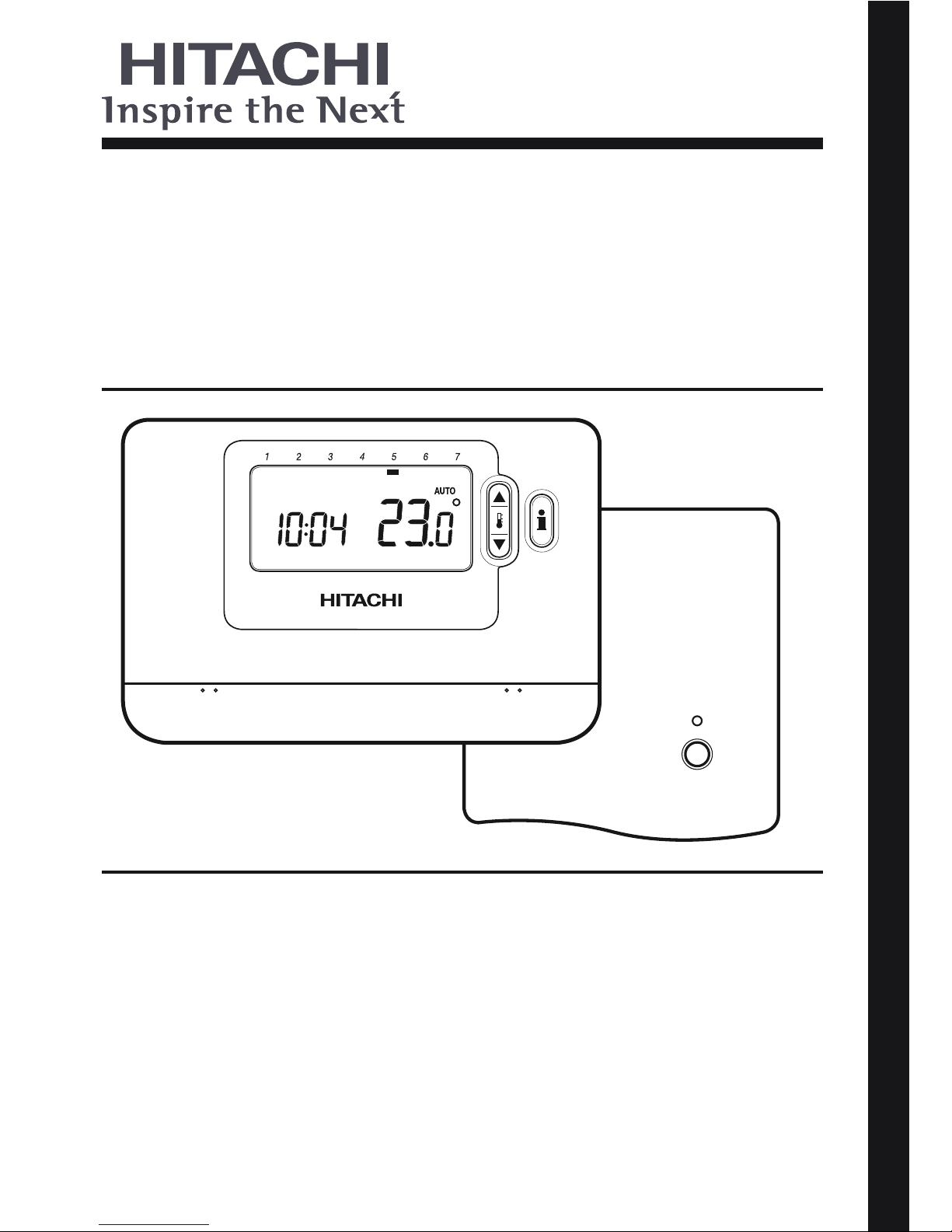
Wireless Programmable Room
Thermostat (ATW-RTU-02)
- Read and understand this manual before performing any operation with the unit. Keep this manual for future reference.
- Lea detenidamente este manual antes de realizar ninguna operación con la unidad. Guarde el manual para futuras
consultas.
- Lesen Sie dieses Handbuch gründlich durch, bevor Sie das Gerät in Betrieb nehmen. Bewahren Sie dieses Handbuch
für inder Zukunft eventuell auftretende Fragen oder Probleme auf.
- Lisez avec attention le contenu de ce manuel avant de réaliser toute opération avec l’unité. Conservez-le an de pouvoir
vous y référer ultérieurement.
- Leggere e comprendere il presente manuale prima di eseguire eventuali operazioni con l’unità. Conservare il presente
manuale per una consultazione futura.
- Leia e compreenda este manual antes de executar qualquer operação com a unidade. Guarde este manual para
referência futura.
- Læs denne vejledning grundigt igennem, inden du anvender enheden. Gem denne vejledning til fremtidig brug.
- Lees deze handleiding zorgvuldig door voordat u een handeling uitvoert met het apparaat. Bewaar deze handleiding
voor naslag.
- Läs noga igenom den här handboken innan du börjar använda enheten. Spara handboken för framtida bruk.
- Διαβάστε προσεκτικά αυτό το εγχειρίδιο πριν εκτελέσετε οποιαδήποτε λειτουργία με αυτήν την μονάδα. Κρατήστε το
εγχειρίδιο για μελλοντική αναφορά.
ΕΛΛΗΝΙΚΆ SVENSKA NEDERLANDS DANSK PORTUGUÊS ITALIANO FRANÇAIS DEUTSCH ESPAÑOL ENGLISH
INSTALLATION AND OPERATION MANUAL
GUÍA DE INSTALACIÓN
EINBAUANLEITUNG
MANUEL D’INSTALLATION ET DE FUNCTIONNEMENT
GUIDA ALL’INSTALLAZIONE
GUIA DE INSTALAÇÃO
MONTERINGSVEJLEDNING TIL RUMENHEDEN
INSTALLATIERICHTLIJNEN
INSTALLATIONSGUIDE
ΟΔΗΓΌΣ ΕΓΚΑΤΆΣΤΑΣΗΣ ΜΟΝΆΔΑΣ ΔΩΜΑΤΊΟΥ
Page 2
2
Description
The Room Unit communicates with the RF Receiver on
an 868MHz Radio Frequency (RF) band to control the Heat
Pump System Controller. Neither product will communicate
with other RF products that use different frequencies or
communication protocols.
Note: The RF link between the Room Unit and RF Receiver
in system packs is pre-configured at the factory and
therefore these components SHOULD be installed at the
same site. This makes the installation process fast and easy,
but if products from individual system packs are separated,
or mixed with other pre-configured system packs during
installations please refer to section 4. Binding / Rebinding
Procedure to bind the desired units together and allow them
to communicate with each other.
Table of Contents
1. Installation Information .........................................................................................................................3
2. Installing the System MMI Pack ............................................................................................................4
2.1 Installing the RF Receiver ..................................................................................................................4
2.2 Installing the Room Unit .....................................................................................................................5
2.2.1 Power Up ....................................................................................................................................5
2.2.2 RF Communication Check ..........................................................................................................5
2.2.3 Locating the Room Unit ..............................................................................................................6
2.3 Communication Loss .........................................................................................................................6
3. Installer Mode .........................................................................................................................................7
3.1 Entering Installer Mode ......................................................................................................................7
3.2 Fail-Safe Mode Setup ........................................................................................................................7
3.3
Using the Room Unit for Specific Applications ..................................................................................8
3.4
Using the Special Features of the Room Unit ....................................................................................8
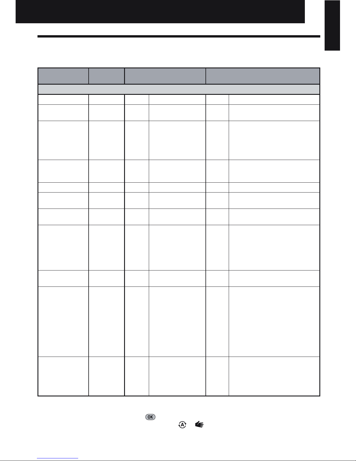
3.5 Installer Parameters Table .................................................................................................................9
3.5.1 Category 1 - Room Unit Settings ................................................................................................9
3.5.2 Category 2 - System Settings ...................................................................................................10
4. Binding / Rebinding Procedure ........................................................................................................... 11
5. Trouble Shooting ..................................................................................................................................12
5.1 Trouble Shooting Guide ...................................................................................................................12
5.2 Diagnostic Mode ..............................................................................................................................12
Installation and Operation Manual
Installation and Operation Manual
Page 3
3
1. Installation Information
As these products communicate using RF technology special care must be taken during installation.
The location of the RF components as well as the building structure may influence performance of the
RF system. To assure system reliability, please review and apply the information given below.
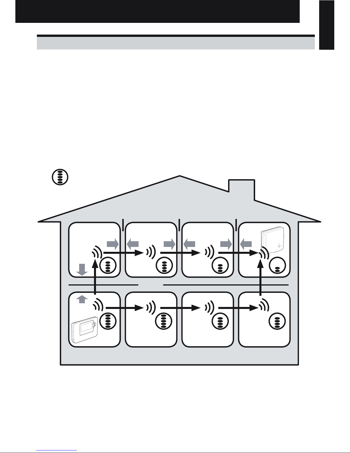
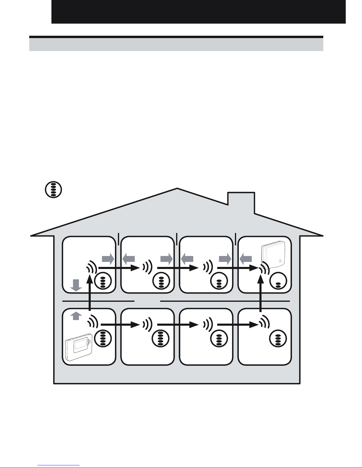
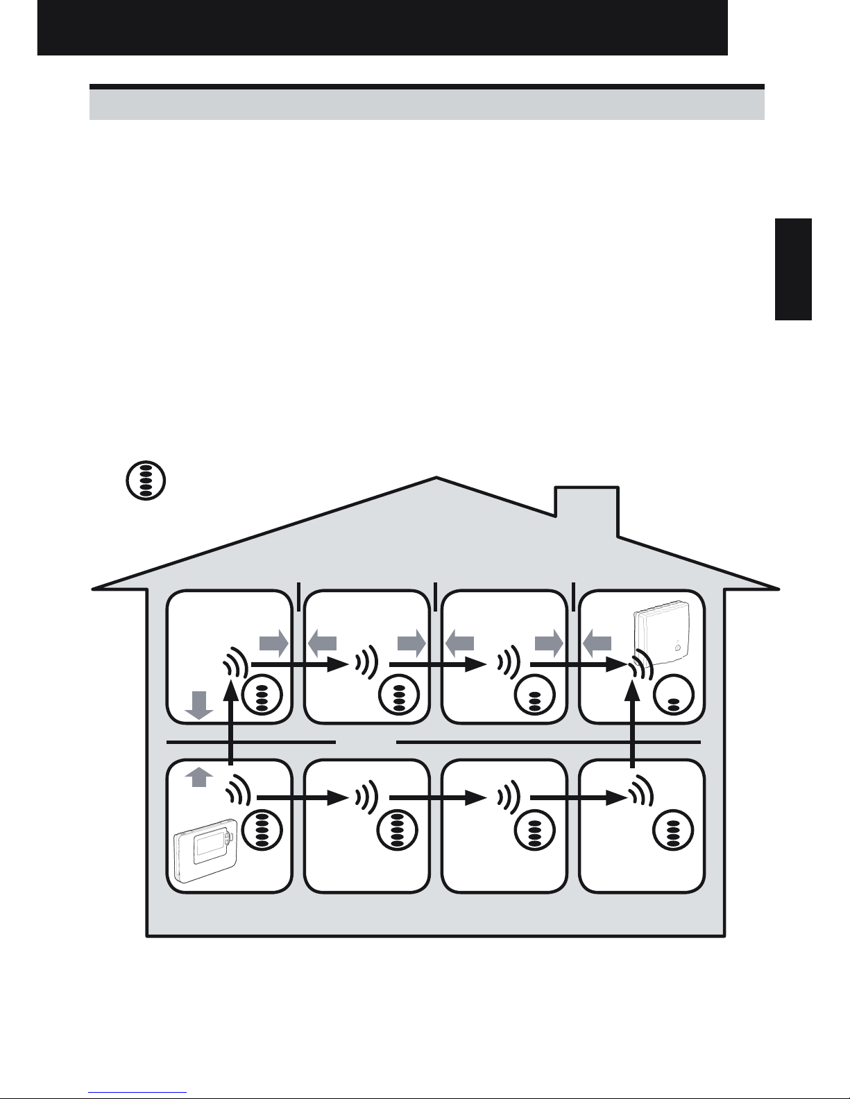
Within a typical residential building the two products should communicate reliably within a 30m range.
It is important to take into consideration that walls and ceilings will reduce the RF signal. The strength
of the RF signal reaching the RF Receiver depends on the number of walls and ceilings separating it
from the Room Unit, as well as the building construction - the diagram below illustrates an example of
typical signal strength reduction. Walls and ceilings reinforced with steel or plasterboard walls lined with
metal foil reduce the RF signal significantly more.
Once a position is selected for the Room Unit this can be checked using the RF Communication Test
mode as described in section 2.2.3 Locating the Room Unit on page 6. If the position is unsuitable the
RF Receiver will not respond and an alternative position for the Room Unit must be selected.
Typical example of Building Fabric Signal losses
Wall Wall Wall
Ceiling
Max. Signal Length 30 metres
= Signal Strength
Installation and Operation Manual
ΕΛΛΗΝΙΚΆ SVENSKA NEDERLANDS DANSK PORTUGUÊS ITALIANO FRANÇAIS DEUTSCH ESPAÑOL ENGLISH
Page 4
4
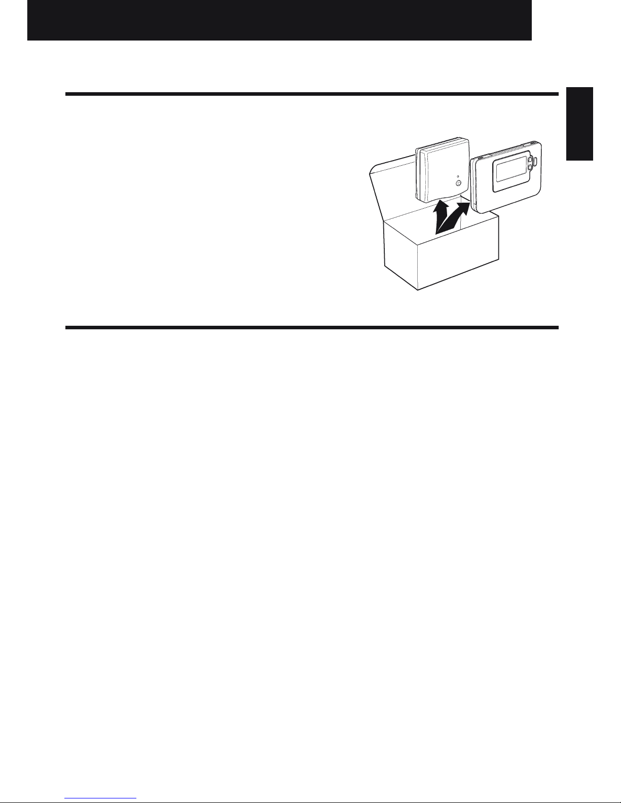
2. Installing the System MMI Pack
Please follow the illustrations and information below in sequence to install the RF Receiver and Room
Unit correctly. To enable special features and see what other system options are available refer to section
3. Installer Mode.
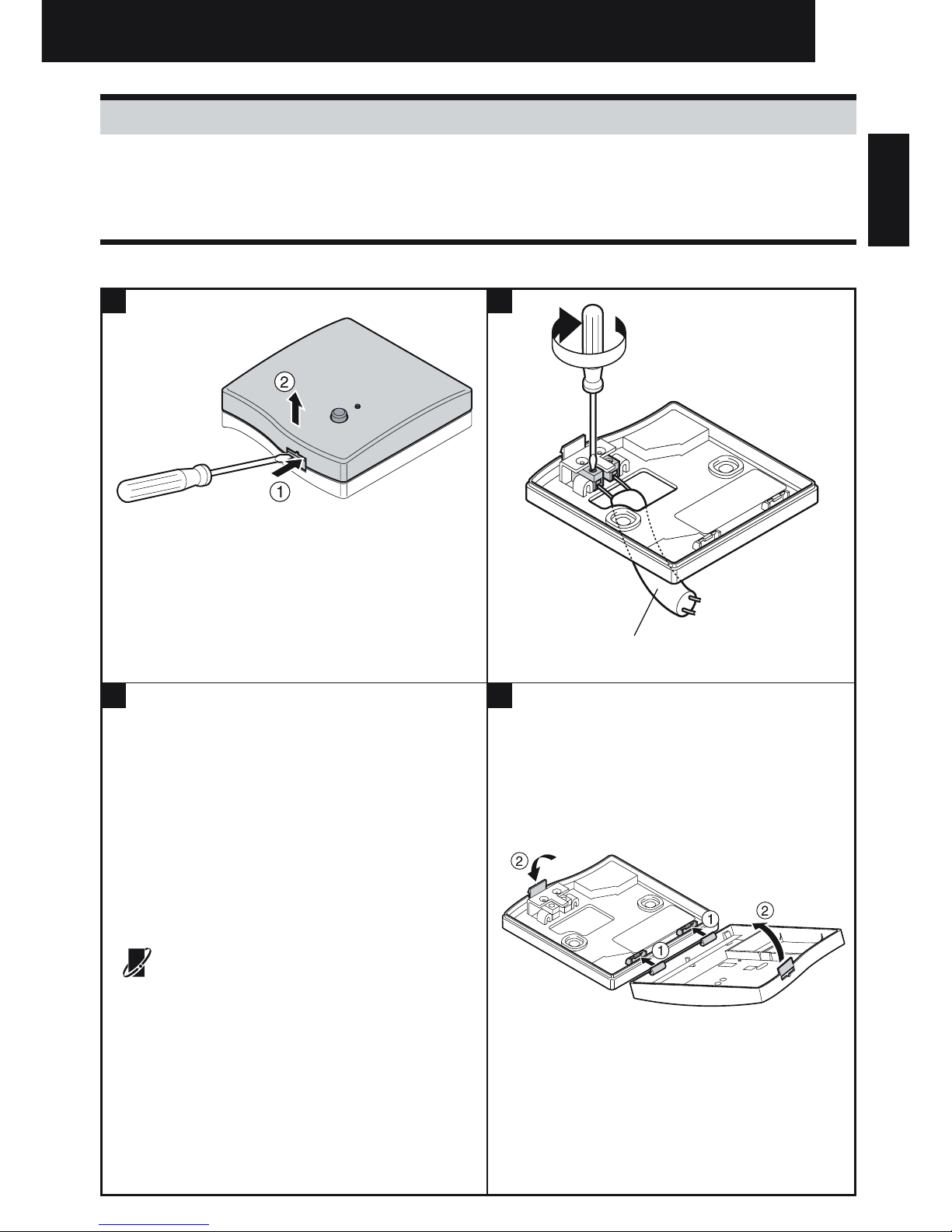
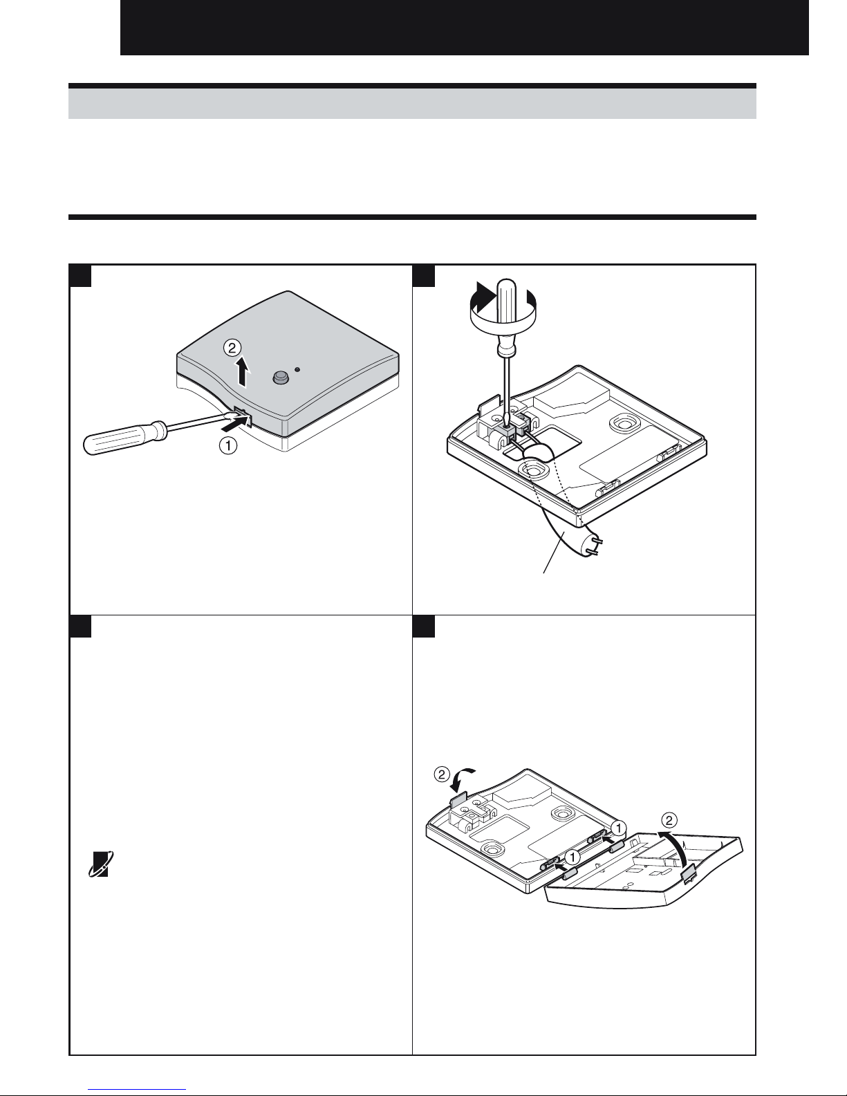
2.1 Installing the RF Receiver
1
NOTE: The RF Receiver contains no user serviceable
parts. It should be opened and installed by qualified
installer only.
WARNING: Electrostatic sensitive device! Do not touch
the circuit board.
NOTE: All wiring must be in accordance with IEE
regulations
CAUTION: Observe ambient temperature and current
limits (see the RF Receiver wiring label)
2
3 4
OpenTherm® - communication
The System MMI Pack can be connected to other
OpenTherm appliances. For the correct wiring
connections refer to the installation manual of the
OpenTherm device.
max. 30m. 2 x 0.5mm2 ; 2 x 0.8mm
2
Installation and Operation Manual
NOTE: For receiver and unit connection refer to
unit installation manual.
Page 5
5
2.2.2 RF Communication Check (Test Mode)
To check the RF communication, hold the Room Unit about 2-3 metres from the installed RF Receiver.
Set the Room Unit to off by pressing the button. then press the and buttons together with the
button for 3 seconds. The unit will display ‘tESt’ and it will send test signals to the RF Receiver. If
the test signals are received the LED on the RF Receiver will flash between 1 and 5 times. The number
of flashes indicates the strength of the radio signal. The higher the number of flashes, the stronger the
signal is.
NOTE: If the LED does not flash or if you are installing a replacement RF Receiver or Room Unit, follow
the procedures described in section 4. Binding / Rebinding Procedure.
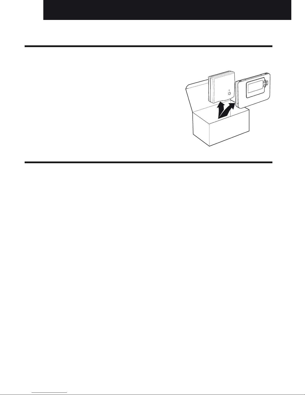
2.2 Installing the Room Unit
2.2.1 Power Up
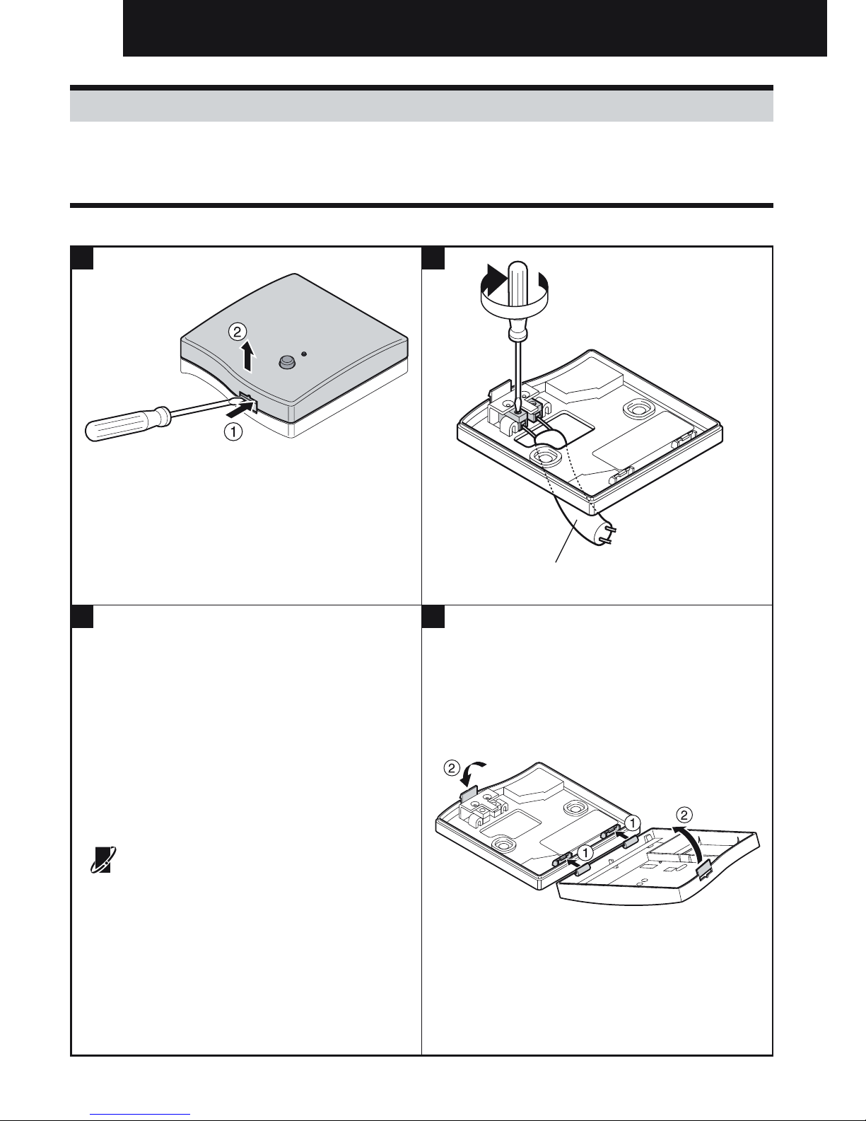
Installing the Batteries:
a. Lift up the front cover of the Room Unit to reveal the battery cover and product controls.
b. Remove the battery cover by pressing down and sliding out.
c.
Insert the 2 x AA LR6 Alkaline Batteries supplied with the Room Unit, ensuring the correct orientation.
d. After a short pause the Room Unit will display information on the screen and is now ready for use.
e. Replace the battery cover by sliding it firmly back into the front of the Room Unit.
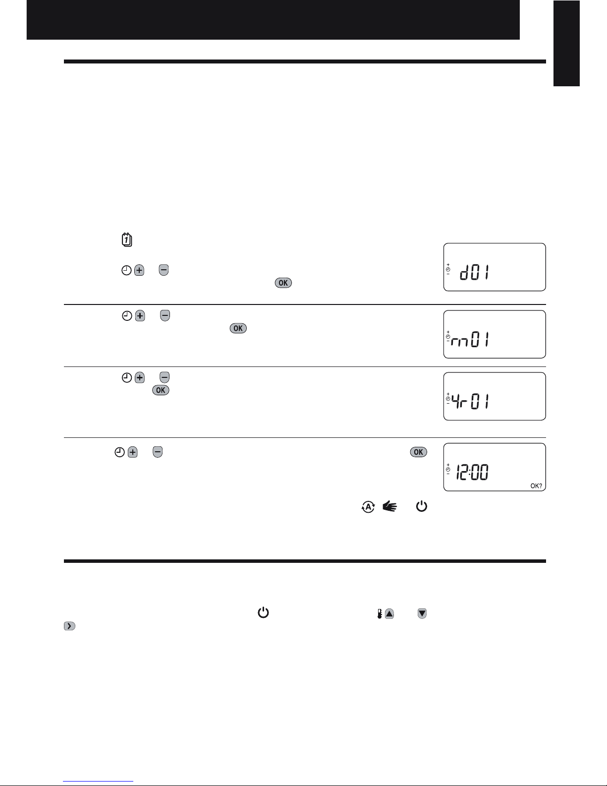
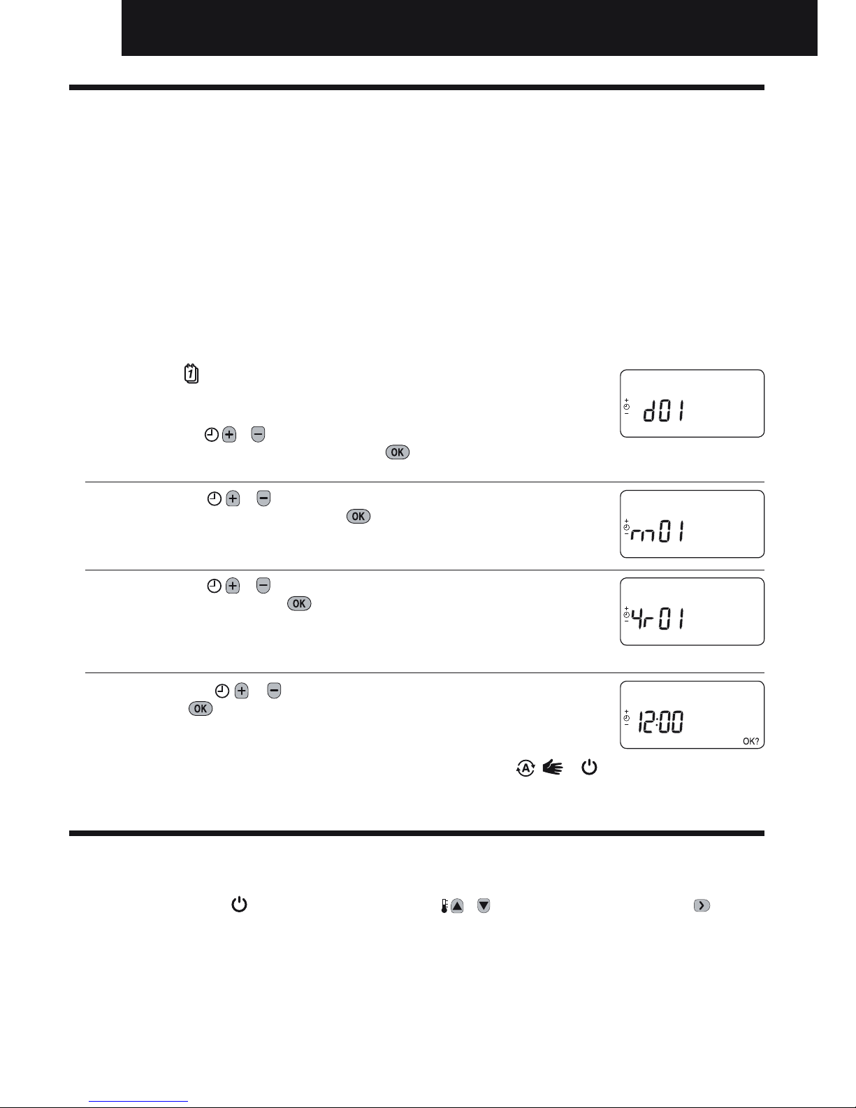
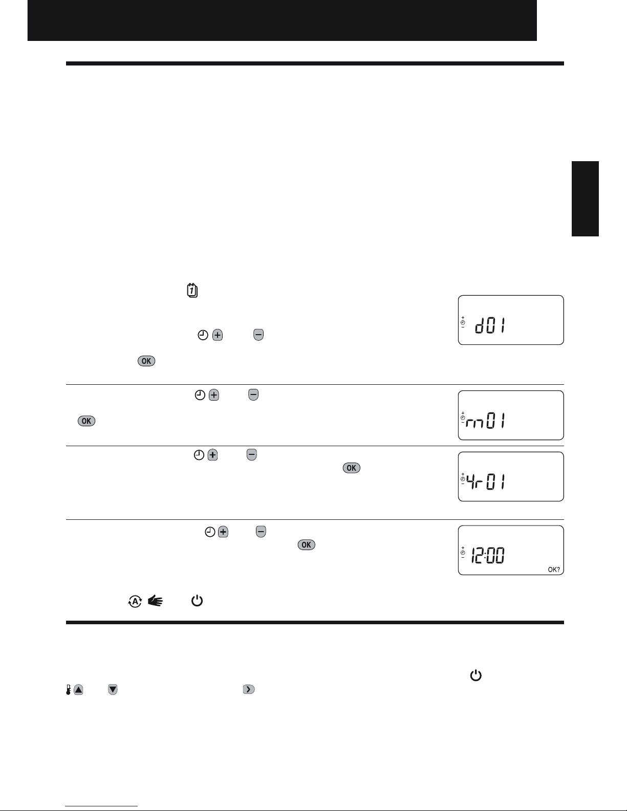
Setting the Date and Time:
a. Press the
button to begin setting the date. When you set the date for the
first time after the batteries are inserted, the display will show:
Press the
or buttons to set the current day of the month (e.g. d 01 =
1st day of the month) then press the green button to confirm.
b. Press the
or buttons to set the current month of the year (e.g. m 01
= January) then press the green button to confirm.
c. Press the
or buttons to set the current year (e.g. yr 09 = 2009) then
press the green button to confirm.
The date is now stored and the Day Indicator will be displayed under the
current day of the week (e.g. 1 = Monday, 2 = Tuesday, etc.)
d. Use the
or buttons to set the correct time then press the green
button to confirm. Each press of the buttons will change the time by one
minute and holding them down will change the time slowly at first and get
progressively quicker.
Note: If this mode is entered accidentally then press the
, or
buttons to exit.
AM
Installation and Operation Manual
ΕΛΛΗΝΙΚΆ SVENSKA NEDERLANDS DANSK PORTUGUÊS ITALIANO FRANÇAIS DEUTSCH ESPAÑOL ENGLISH
Page 6
6
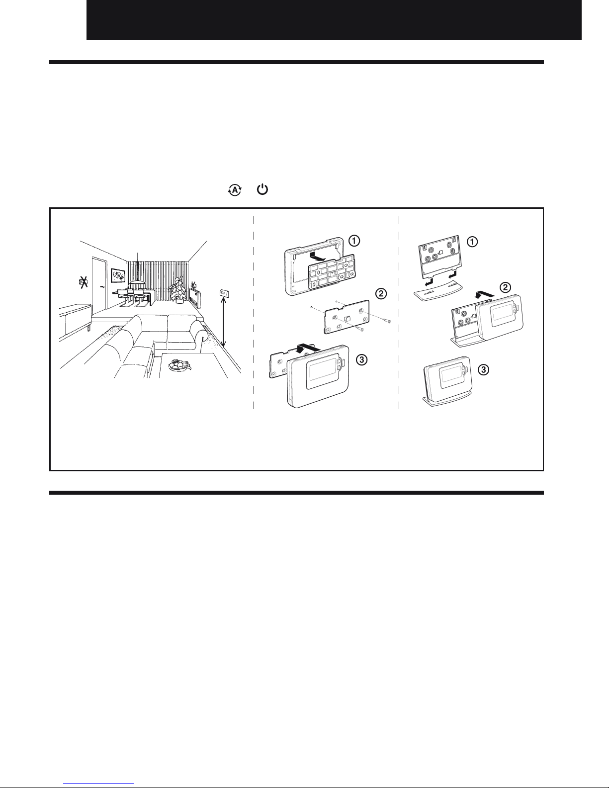
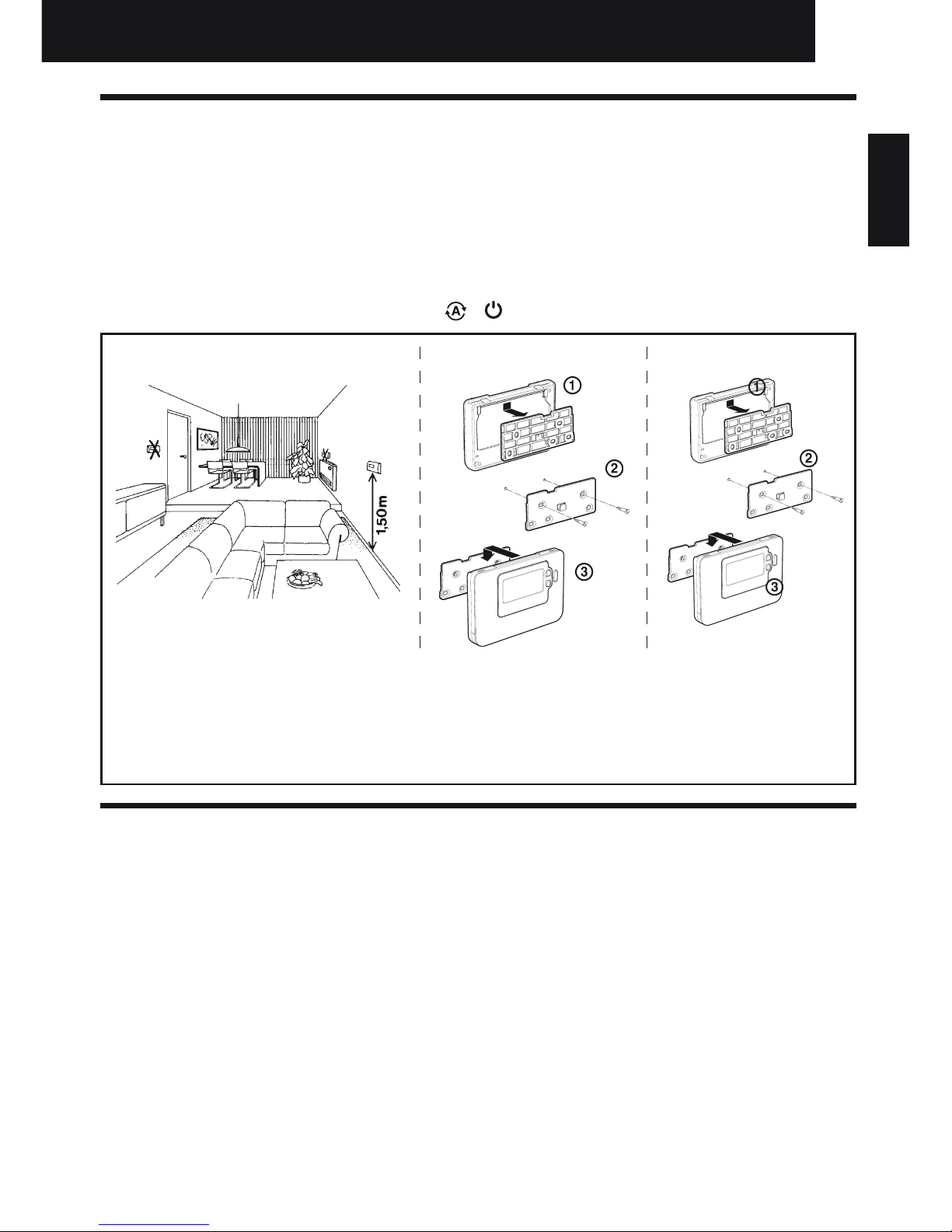
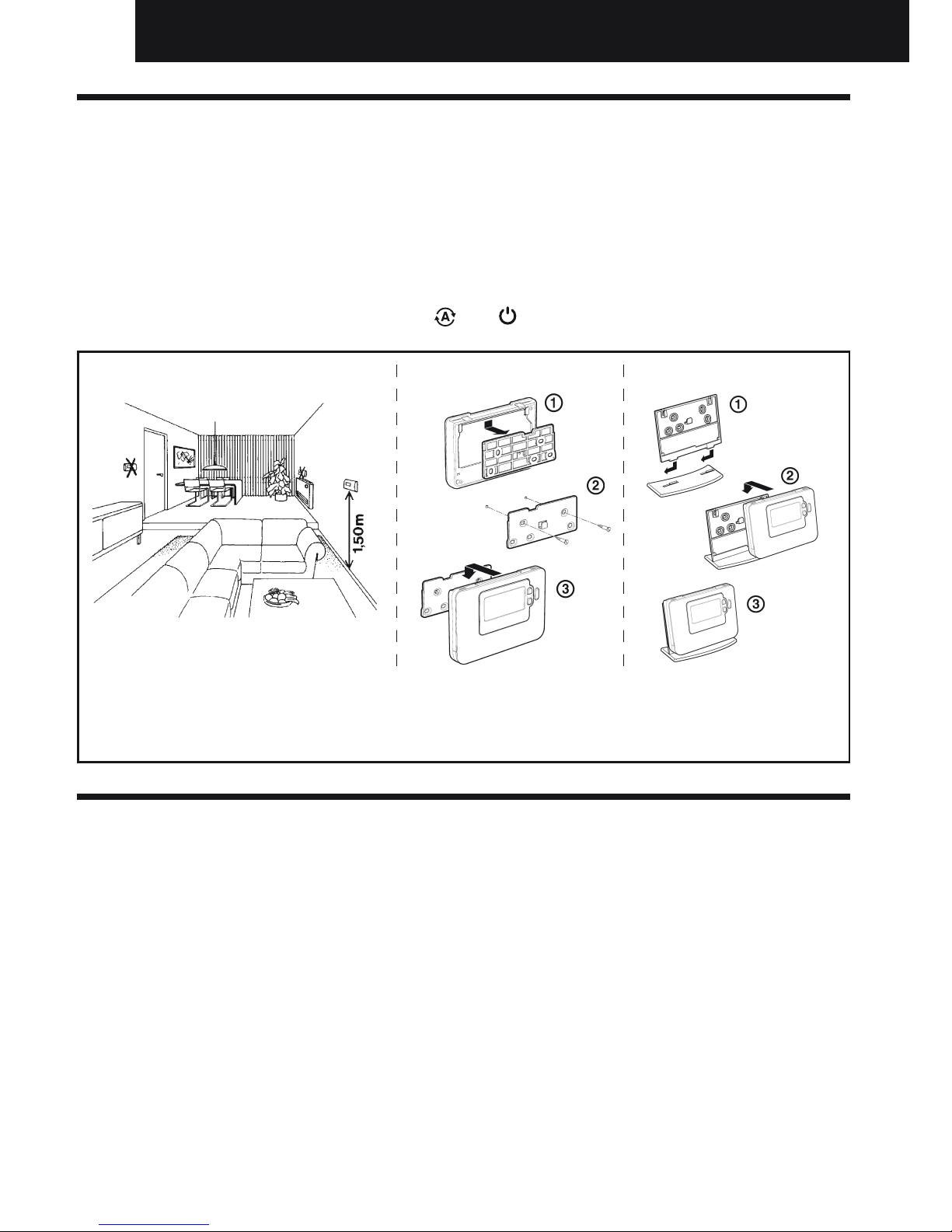
2.2.3 Locating the Room Unit
While still in the Test Mode, as described in section 2.2.2, the Room Unit should be located taking the
following into consideration and reviewing the illustrations below:
1. Find a suitable location where the signal transmission is reliable. Reliable transmission is indicated
when the RF Receiver is flashing the green LED every 6 seconds.
2. Install the Room Unit EITHER on the wall using the wall bracket OR attach the optional table stand as
shown in below.
3. Exit the Test Mode by pressing the
or button.
Wall bracket Table stand
•TheRoom Unit should be installed in an open space for best performance as it is a radio frequency device.
•
Leave at least 30cm distance from any metal objects including wall boxes and at least 1 metre from any other
electrical equipment eg. radio, TV, PC etc.
•Donotmountontometalwallboxes.•ItisrecommendedthattheRF Receiver is fully installed.
2.3 Communication Loss
In the event of an RF communications loss, the LED on the RF Receiver will indicate which type of fault
has occurred.
• IfthereisacommunicationsfaultbetweentheRF Receiver and the Room Unit, then the LED on the
RF Receiver will flash red for 0.1 sec ON every three seconds
• IfthereisafaultincommunicationsbetweentheboilerorSystem Controller, then the LED on the RF
Receiver will flash 3 times quickly and then be off for three seconds,
• IfthereismorethanoneRoom Unit installed, as in multi-zone systems for example, and communications
is lost with one zone, then the red LED on the RF Receiver will flash two times quickly and then be off
for two seconds.
• IfthereismorethanoneRoom Unit installed, as in multi-zone systems for example, and communications
is lost with both zones, then the red LED on the RF Receiver will flash once for 0.1 sec ON, and 0.9 sec
OFF.
Once the faulty device has been identified, replace as necessary and follow the re-binding procedure as
described in section 4. Binding / Rebinding Procedure.
Installation and Operation Manual
1.2-1.5m
Page 7
7
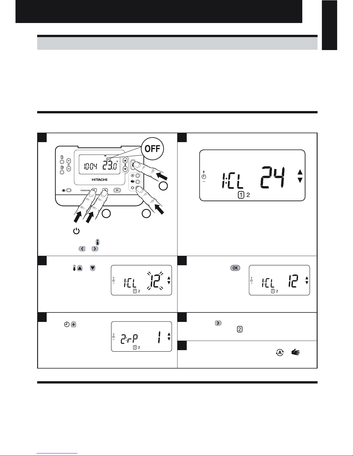
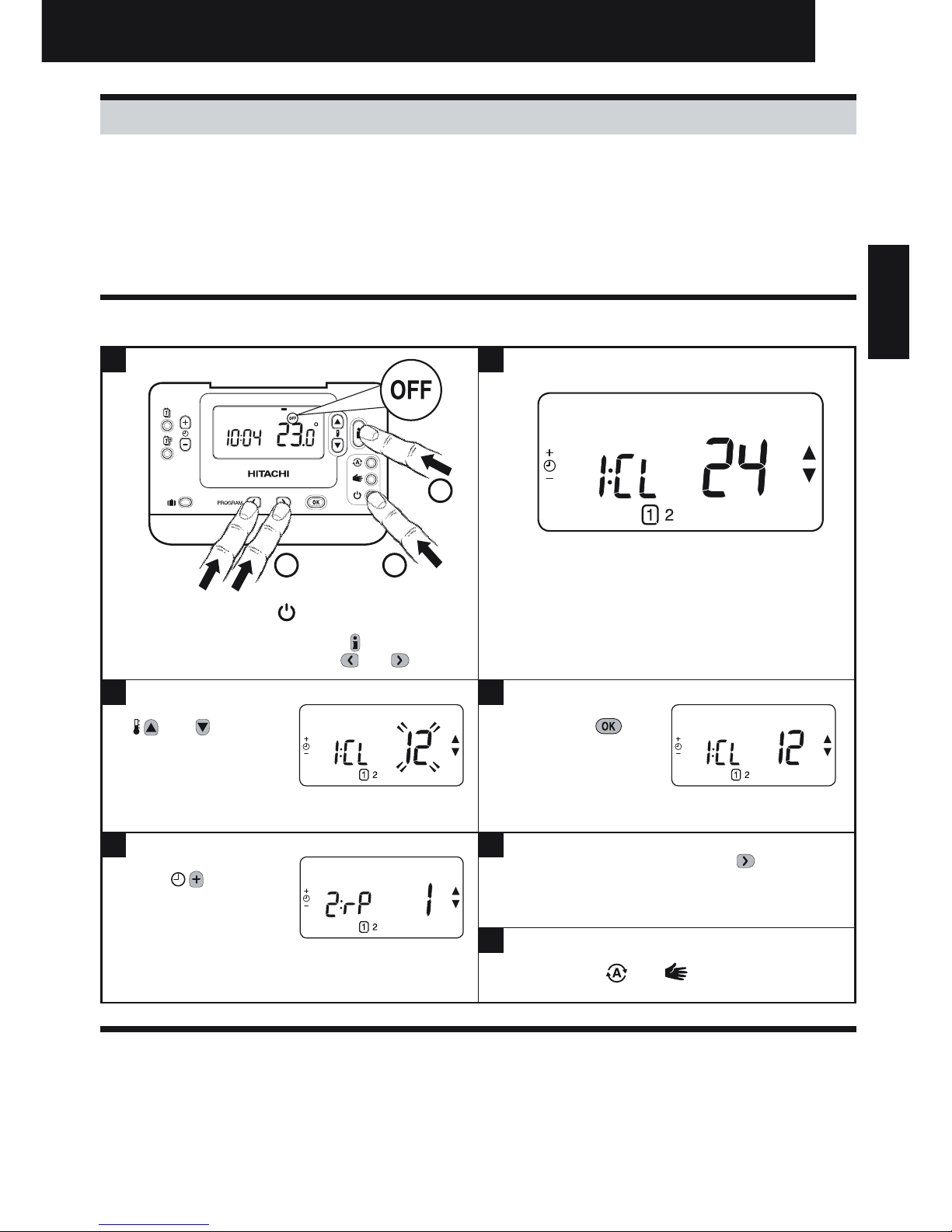
3.1 Entering Installer Mode
3.2 Fail-Safe Mode Setup
The fail-safe mode defines the system status if the RF communication is lost (e.g. when the Room Unit
stops communicating due to discharged batteries). If the system is a direct (radiator one), then the
factory setting will make the system revert to a set point of 10°C for frost protection. If indirect loops are
added, the system will continue to operate at the last communicated setpoint.
3. Installer Mode
Installer Mode is used to alter the system settings for specific applications, to use the special features
of the Room Unit in a different way or to alter the factory preset parameters. Parameters are divided
into two groups:
- Category 1 parameters – Room Unit Setup
- Category 2 parameters – System Setup.
These are all listed in section 3.5 Installer Parameters Table.
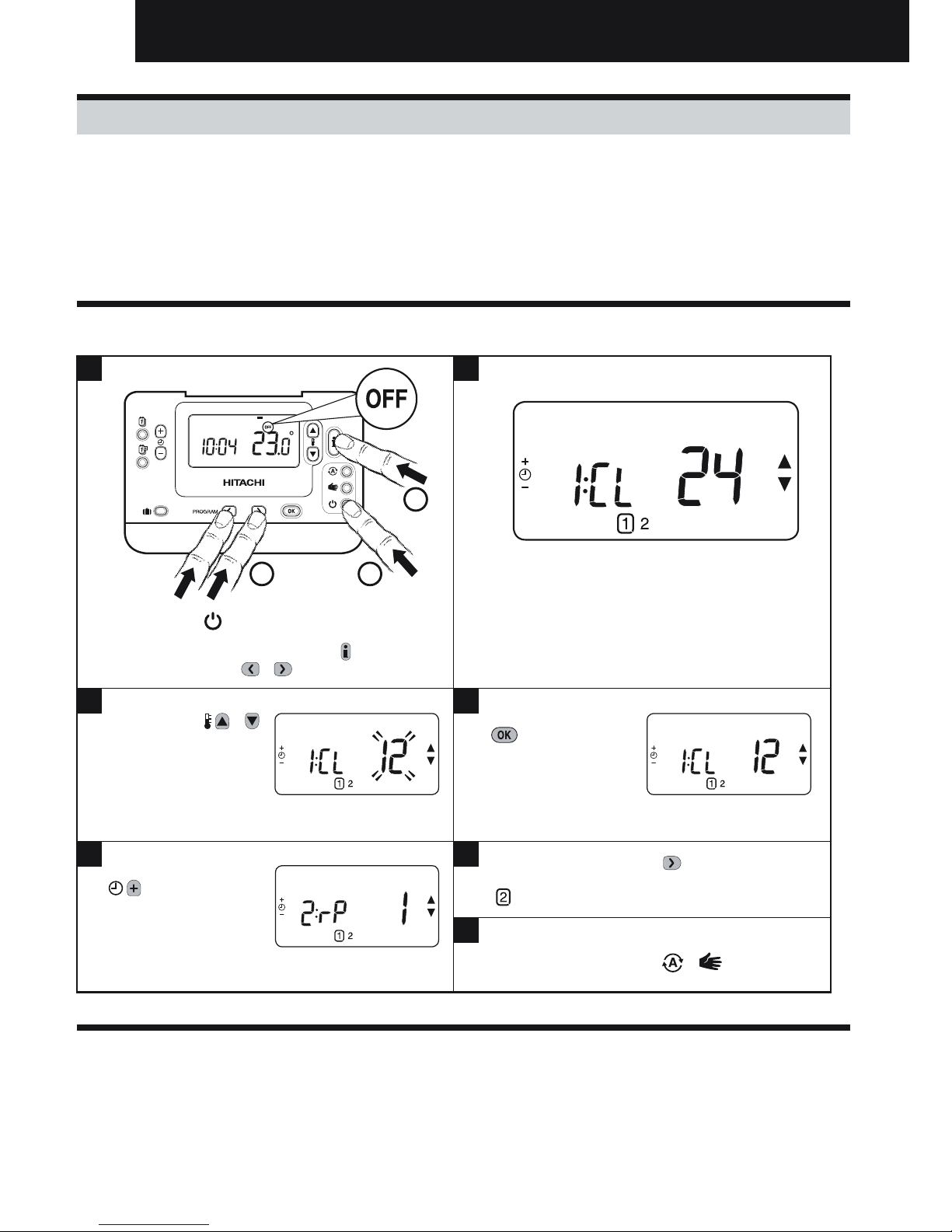
Press the button.
Press and hold the
button and the
PROGRAM & buttons together.
Press the
or to
change factory setting.
The display will flash
indicating that a change
has been made.
Press the green
button to confirm the
change.
The display will stop
flashing.
Press the
button to go to Installer parameter
group category 2 (
) (from Parameter n.4 to n.14).
To exit the installer mode press the
or
buttons.
Press
button
to go to the next
parameter.
The unit will display the first parameter of installer
parameter group category 1 (from Parameter n.1
to n.19) as shown
1 2
3 4
5 6
7
1..6
MANAUTO
1 2 3 4 5 6 7
1
2
2
ENGLISH
Installation and Operation Manual
ΕΛΛΗΝΙΚΆ SVENSKA NEDERLANDS DANSK PORTUGUÊS ITALIANO FRANÇAIS DEUTSCH ESPAÑOL ENGLISH
Page 8
8
3.3 Using the Room Unit for Specic Applications
The Room Unit is a versatile controller that can be used to control many different applications. Please note
that when the Room Unit is installed in conjunction with a System Controller, the functionality will differ to
that when installed with a standard boiler system. Most of the functions shown below will be controlled by
the System Controller and be set within its parameters. Therefore, some of the system parameters within
the Room Unit menu will not apply. Please also note other changes to the setting of the optimisation and
proportional band settings as shown in tables 3.5.1 and 3.5.2.
NOTE: In order for the Room Unit to send the heating demand signal to the RF Receiver, it is essential that
the Category 2 parameter 8:Su is set to the correct value (see Installer Parameters Table, 3.5.2 Category
2 – System Settings). Failure to do this will mean that the heating system will not respond to changes in
the setpoint on the Room Unit. Under these circumstances the system will operate with no input from the
Room Unit and may not therefore provide adequate temperature control.
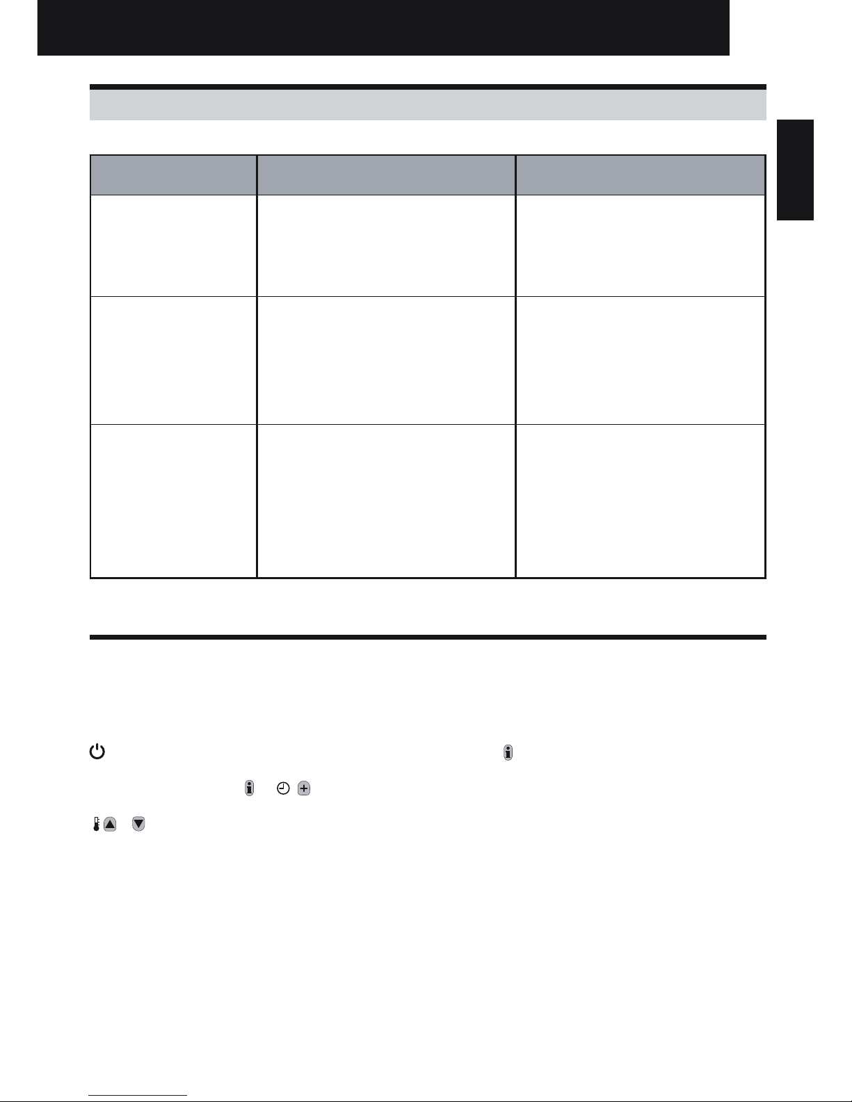
3.4 Using the Special Features of the Room Unit
Special Feature: Description: Enable/Disable
Heating or Cooling
Operation
This product can be used for heating or cooling
applications. If you select cooling mode the control
algorithm and factory default program will be modified. You
can independently modify the heating and cooling profile.
To enable: Set parameter 4:HC
(category 2) to 1.
Summer/Winter
Auto time change
This feature moves time automatically on the last Sunday
of March and the last Sunday of October. The feature is
factory enabled.
To enable: Set parameter 3:tC
(category 1) to 1.
Temperature Offset If the Room Unit is located in a particularly hot/cold
location for reliable signal transmission reasons then the
measured/displayed temperature can be adjusted by +/3°C. This is useful if the homeowner wants the reading to
match another appliance temperature display.
Set parameter 12:tO (category
1) to the required offset value.
Upper/Lower
Temperature Limit
The normal upper temperature limit of 35°C can be
reduced to 21°C to save the homeowner energy. The
normal lower limit of 5°C can be increased up to 21°C to
protect inhabitants from cold.
Set parameter 6:uL (category 1)
to the desired upper limit.
Set parameter 7:LL (category 1)
to the desired lower limit.
Installation and Operation Manual
Page 9
9
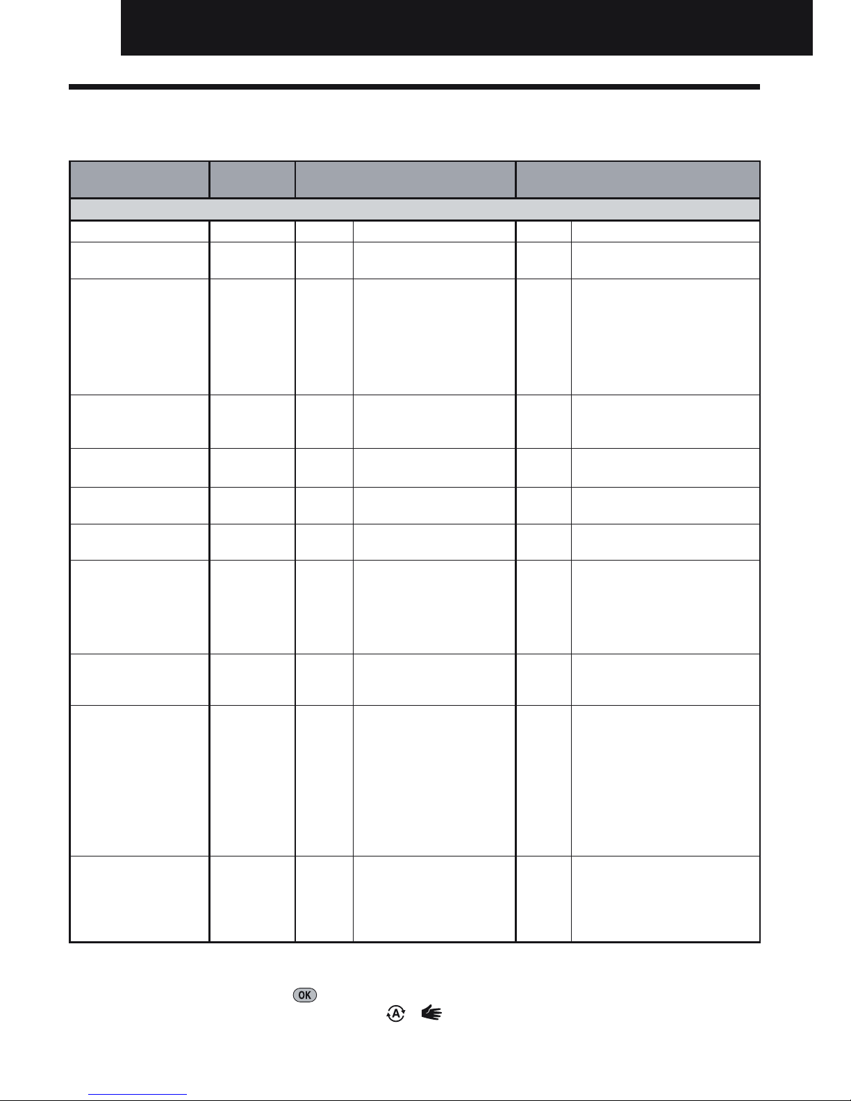
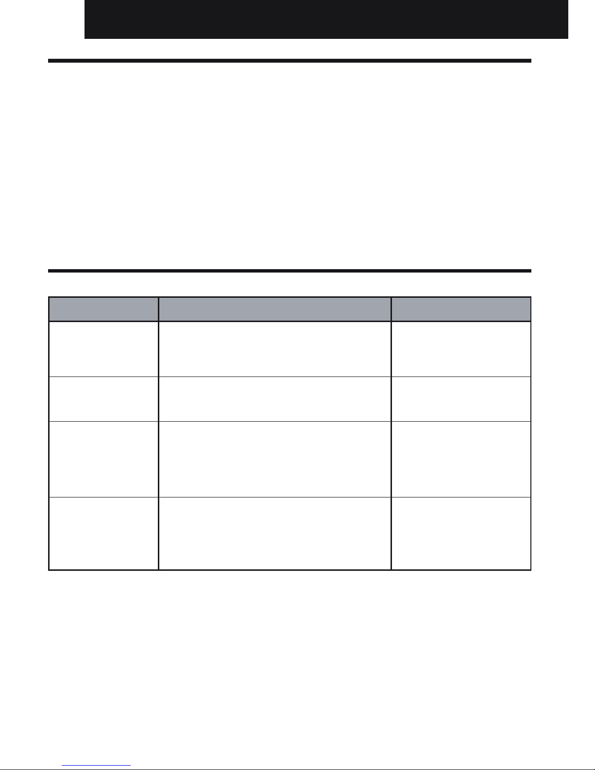
3.5 Installer Parameters Table
3.5.1 Category 1 - Room Unit Settings
Note
Remember to always press the green
button to confirm that you want to store your new Installer
Set-Up setting. To exit the Installer Mode press the or button.
Parameter Parameter
No.
Factory Default Setting Optional Setting
Category 1 Parameters – Room Unit Settings
Display Description Display Description
AM-PM / 24hr
Display
1:CL 24 24 hr clock display
format
12 12 hr – AM/PM clock display
format
Reset Time/ Temp
Program
2:rP 1 Time / Temp profile
set to factory default
Changes to 0 when
one of the time/temp
profiles are changed
0 Time / Temperature are as
programmed
To restore the factory profile set
to 1
Auto Summer/
Winter Time
Change
3:tC 1 Auto Summer/
Winter Time Change
Enabled
0 Auto Summer/Winter Time Change
Disabled
LCD Backlighting 5:bL 1 Backlighting Enable 0 Backlighting Disabled
Upper Temp Limit 6:uL 35 35°C Upper Temp.
Limit
21 to 3421°C to 34°C adjustment in 1°C
steps
Lower Temp Limit 7:LL 5 5°C Lower Temp.
Limit
5 to 21 6°C to 21°C adjustment in 1°C
steps
Optimisation
Note: This
parameter will
not function
with the System
Controller.
8:OP 0 Optimisation
Disabled
1 Optimisation Enabled
DO NOT CHANGE
Temperature
Offset
12:tO 0 No temperature
offset
-3 to +3-3°C to +3°C adjustment in 0.1°C
steps
Proportional Band
Width
Note: This
function is for
use with the
extension system
only. It will not
function with
the System
Controller alone
13:Pb 1.5 Proportional band of
1.5 degrees
1.6 to
3.0
1.6°C to 3.0°C adjustment in 0.1°C
steps
Reset Parameters
to Factory
Defaults
19:FS 1 All settings at factory
defaults
Changes to 0 when
one of the parameter
is changed
0 Settings are as modified above
To restore the factory profile set
to 1
Installation and Operation Manual
ΕΛΛΗΝΙΚΆ SVENSKA NEDERLANDS DANSK PORTUGUÊS ITALIANO FRANÇAIS DEUTSCH ESPAÑOL ENGLISH
Page 10
10
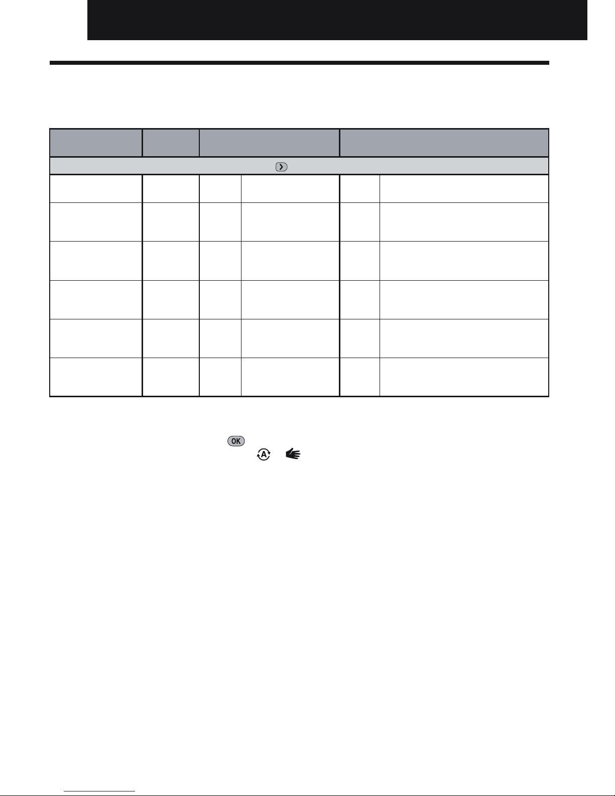
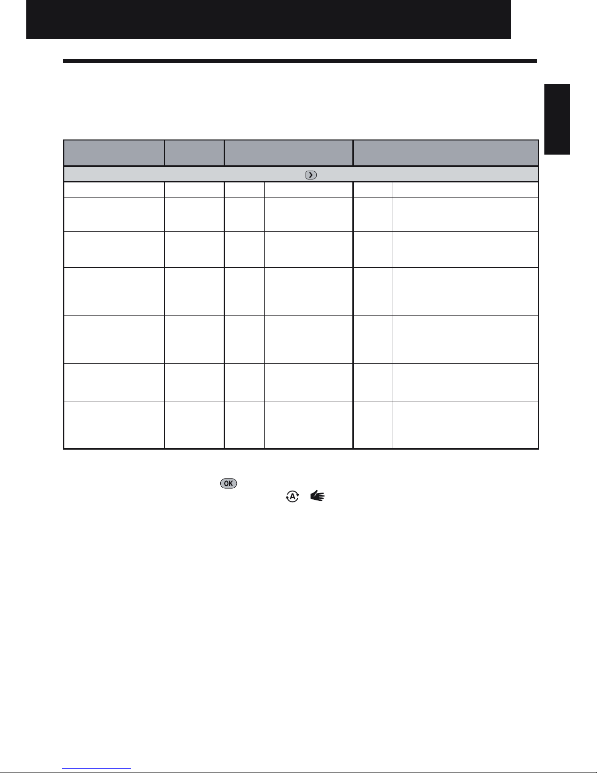
3.5.2 Category 2 - System Settings
NOTE: To ensure correct heat pump system operation, parameter 8:Su must be set correctly. See note in
section 3.3 Using the Room Unit for Specic Applications.
Note
Remember to always press the green
button to confirm that you want to store your new Installer Set-Up
setting. To exit the Installer Mode press the or button.
Parameter Parameter
No.
Factory Default Setting Optional Setting
Category 2 Parameters – System Settings (press the
button to access this category)
Heat/Cool selection
enable / disable
4:HC 0 Disabled 1 Enabled
Room Temperature
Sensor Use
8:Su 0
Programmer and
room compensation
unit
1
Programmer only. Transmits demand
and room setpoint (no temperature
displayed)
Maximum Flow
Setpoint (extension
systems only)
11:uF 55
55°C Maximum Flow
Temp.
0 to 99 0°C to 99°C adjustment in 1°C steps
Minimum Flow
Setpoint (extension
systems only)
12:LF 15
15°C Minimum Flow
Temp.
0 to 50 0°C to 50°C adjustment in 1°C steps
Mixing Value Run
Time (extension
systems only)
13:Ar 150 150 seconds
0 to
240
0 to 240 sec. adjustment in 1sec
steps
Pump Overrun Run
Time (extension
systems only)
14:Pr 15 15 minutes 0 to 99 0 to 99 mins adjustment in 1min steps
Installation and Operation Manual
Page 11

11
4. Binding / Rebinding Procedure
NOTE: For binding / Rebinding procedure refer to unit installation manual.
Installation and Operation Manual
ΕΛΛΗΝΙΚΆ SVENSKA NEDERLANDS DANSK PORTUGUÊS ITALIANO FRANÇAIS DEUTSCH ESPAÑOL ENGLISH
Page 12
12
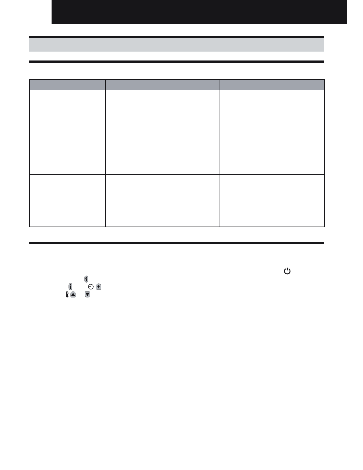
5. Trouble Shooting
5.1 Trouble Shooting Guide
Symptom (Fault Message) Possible Cause Remedy
The RF Receiver does not
react to setpoint changes
on the Room Unit.
The Room Unit and RF Receiver are not
bound or the installer parameter 8:Su has
not been set correctly.
Make sure that the 8:Su parameter
value is set correctly. Reset the RF
Receiver by pressing and holding
the push button for 15 seconds.
Then follow the binding / rebinding
procedure as described in section 4.
Binding / Rebinding Procedure.
After the binding procedure
the red LED continues to
flash on the RF Receiver.
Incorrect or incomplete binding procedure.
Incorrect position of the Room Unit during
binding.
Repeat the binding procedure.
Repeat the binding procedure keeping
approx. 1m distance between the RF
Receiver and the Room Unit.
The red LED is on the RF
Receiver (Communication
loss)
The RF Receiver receives no RF messages
from the Room Unit:
RF signal is blocked due to wrong location
of the Room Unit.
Room Unit batteries are exhausted.
Re-locate the Room Unit following
instructions in section 2. Installing the
System MMI Pack.
Replace batteries in the Room Unit.
5.2 Diagnostic Mode
The Room Unit has a user accessible mode that provides information useful to a remote service person
and a means of checking whether the heating system is working. To access this press the button then
press and hold the button for 5 seconds. The Room Unit will enter the user settings mode. Next press
and hold the and buttons together. The following information can be viewed on the display by
pressing the or buttons : model ID, date code (WW/YY) & checksum.
Hereby, HITACHI declares that this Room Unit and RF Receiver are in compliance with the essential
requirements and other relevant provisions of Directive 1999/5/EC, 2006/95/EC and 2004/108/EC.
Installation and Operation Manual
Page 13
13
Descripción
El termostato de ambiente se comunica con el receptor
en una banda de radiofrecuencia (RF) de 868 MHz para
controlar un solo componente del sistema de calefacción,
como una caldera, una bomba o una válvula de zona.
Nota: La comunicación RF entre el termostato ambiente
y el receptor en packs suministrados está preconfigurada
en fábrica y por ello DEBEN instalarse juntos. Esto hace
que el proceso de instalación sea fácil y rápido. Pero si se
separan productos de packs individuales, o si se mezclan
con otros packs preconfigurados, consulte la sección 4.
Procedimiento de reconocimiento para sincronizar de
nuevo entre sí las unidades deseadas y permitir que se
comuniquen.
Índice
1. Información para la instalación ......................................................................................................14
2. Instalando el sistema MMI ...............................................................................................................15
2.1 Instalando el receptor ..................................................................................................................15
2.2 Instalando el termostato de ambiente .........................................................................................16
2.2.1 Encendido ............................................................................................................................16
2.2.2 Comprobación de comunicaciones .....................................................................................16
2.2.3 Ubicación del termostato de ambiente ................................................................................17
2.3 Pérdida de la comunicación ........................................................................................................17
3. Modo instalador ...............................................................................................................................18
3.1 Entrar en el modo instalador ........................................................................................................18
3.2 Configuración en modo a prueba de fallos .................................................................................18
3.3 Uso del termostato de ambiente para aplicaciones específicas ................................................19
3.4 Uso de las Características Especiales del Termostato ...............................................................19
3.5 Tabla completa de parámetros del instalador .............................................................................20
3.5.1 Categoría 1 - Ajustes del Termostato de ambiente ..............................................................20
3.5.2 Categoría 2 - Ajustes del Sistema ........................................................................................21
4. Procedimiento de reconocimiento .................................................................................................22
5. Resolución de problemas ...............................................................................................................23
5.1 Guía para la resolución de problemas ........................................................................................23
5.2 Modo diagnóstico ........................................................................................................................23
Guía de Instalación
ΕΛΛΗΝΙΚΆ SVENSKA NEDERLANDS DANSK PORTUGUÊS ITALIANO FRANÇAIS DEUTSCH ESPAÑOL ENGLISH
Page 14
14
1. Información para la instalación
Dado que estos productos se comunican con tecnología de RF, debe tenerse un especial cuidado durante
la instalación. La ubicación de los componentes de RF así como la estructura del edificio pueden afectar
el rendimiento del sistema de RF. Para asegurar la fiabilidad del sistema, revise y aplique la información
que se da a continuación.
Dentro de un edificio residencial típico, los dos componentes deben comunicarse de manera fiable con
un alcance de 30 metros. Es importante tener en cuenta que paredes y techos reducen la señal de RF.
La intensidad de la señal de RF que llega al receptor depende del número de paredes y techos que le
separan del termostato de ambiente y, además, de la construcción del edificio – el diagrama siguiente
ilustra un ejemplo de reducción típica de la intensidad de señal. Las paredes y techos reforzados con
acero o las paredes de panel de yeso recubiertas con láminas metálicas reducen mucho más la señal
de RF.
Una vez se ha seleccionado la posición del termostato de ambiente, esto puede comprobarse usando
el modo Prueba de Comunicación de RF, que se describe en la sección 2.2.3 Ubicación del termostato
de ambiente. Si la posición es inadecuada, el receptor no responderá y deberá elegirse una posición
alternativa.
Ejemplo típico de la pérdida de señal por la construcción del edicio
Pared Pared Pared
Techo
Alcance máximo de señal 30 m.
= Intensidad de la señal
Guía de Instalación
Page 15
15
2. Instalando el sistema MMI
Siga la secuencia de ilustraciones e información que hay más adelante para instalar correctamente el
receptor y el termostato de ambiente. Para aplicaciones distintas de una caldera de gas, para activar
las características especiales y para ver qué otras opciones están disponibles en el sistema, consulte
la sección 3. Modo de Instalador.
2.1 Instalando el receptor
NOTA: El receptor no contiene elementos para el
usuario. Sólo debe abrirlo e instalarlo un instalador
cualificado.
ADVERTENCIA: ¡Aparato sensible a cargas
electrostáticas! No toque la tarjeta de circuito impreso.
NOTA: Todo el cableado debe ser acorde con las
normativas locales.
PRECAUCIÓN: Observe los límites de temperatura
ambiente y de intensidad (vea la etiqueta de
conexiones del receptor)
1 2
3 4
OpenTherm® - communication
El sistema MMI puede conectarse a otros aparatos
OpenTherm. Para ver las conexiones correctas de cableado consulte el manual de instalación del dispositivo
OpenTherm.
max. 30m. 2 x 0.5mm2 ; 2 x 0.8mm
2
Guía de Instalación
ΕΛΛΗΝΙΚΆ SVENSKA NEDERLANDS DANSK PORTUGUÊS ITALIANO FRANÇAIS DEUTSCH ESPAÑOL ENGLISH
NOTA: Para la conexión del receptor y de la unidad
consulte el manual de instalación de la unidad
Page 16
16
2.2 Ajuste de la fecha
2.2.1 Encendido
Para instalar las Pilas:
a. Levante la cubierta frontal del termostato para dejar al descubierto la tapa del compartimento para las
pilas y los controles del termostato.
b. Retire la tapa del compartimento para las pilas presionándola y deslizándola hacia abajo .
c. Inserte las 2 Pilas Alcalinas AA LR6 que se suministran con el termostato, asegurándose de tener la
orientación correcta.
d.
Tras una breve pausa, el termostato mostrará información en la pantalla y estará listo para ser utilizado.
e. Vuelva a colocar la tapa del compartimento para las pilas deslizándola firmemente hacia arriba.
Ajuste del Día y la Hora
a. Pulse el botón
para iniciar el ajuste de la fecha. Cuando se vaya a ajustar
la fecha por primera vez después de la inserción de las pilas, en la pantalla
aparecerá:
Pulse los botones
o para ajustar el día actual del mes (p. ej. d 01 = 1er
día del mes) y después pulse el botón verde para confirmar.
b. Pulse los botones
o para ajustar el mes actual del año (p. ej. m 01 =
Enero) y después pulse el botón verde
para confirmar.
c. Pulse los botones
o para ajustar el año actual (p. ej. yr 09 = 2009) y
después pulse el botón verde para confirmar.
La fecha está ahora guardada y el Indicador de Día se visualizará debajo del
día actual de la semana (p. ej. 1= Lunes, 2 = Martes, etc.)
d. Utilice los botones
o para ajustar la hora correcta y después pulse
el botón verde para confirmar. Cada vez que se pulsen los botones se
cambiará la hora en un minuto, y al mantenerlas pulsadas, se cambiará la
hora, primero lentamente y luego cada vez más rápido.
Nota: si se accede a este modo accidentalmente, pulse el botón
, u
para salir.
2.2.2 Comprobación de comunicaciones
Para comprobar la comunicación de RF, mantenga el termostato de ambiente a unos 2-3 metros del
receptor. Pulse el botón y después pulse los botones y simultáneamente con el botón durante
3 segundos. La unidad mostrará tESt y enviará señales de prueba al receptor, el LED verde parpadeará
cada 5 segundos ( el relé permanecerá desconectado) durante un máximo de 10 minutos. Cuando el LED
verde parpadee cada 5 segundos, prosiga al paso siguiente.
REMARQUE : Si el LED verde no se conecta a los intervalos especificados, si el LED rojo parpadea, o
si está instalando un receptor o un termostato de recambio, siga los pasos descritos en la sección 5.1
Procedimiento de Reconocimiento.
AM
Guía de Instalación
Page 17
17
2.2.3 Ubicación del termostato de ambiente
Estando aún en el modo TEST, tal como se ha descrito, debe situarse el termostato de ambiente
teniendo en cuenta lo siguiente y revisando las ilustraciones debajo:
1. Encuentre una ubicación aceptable, donde la transmisión de la señal sea fiable. Una transmisión
fiable se indica por el LED verde del receptor parpadeando cada 5 segundos. NOTA: El relé del
receptor estará desconectado.
2. Instale el termostato en la pared, usando el soporte de pared o colóquelo en el pie de sobremesa
opcional, tal como indica la ilustración debajo.
3. Para salir del modo de
TEST,
pulse el botón o .
2.3 Pérdida de la comunicación
En el caso de una pérdida de la comunicación de RF, el LED del Receptor indicará qué tipo de fallo
se ha producido.
• En caso de fallo de comunicaciones entre el Receptor y la Termostato, el LED del Receptor
parpadeará en rojo durante 0,1 seg en ON cada tres segundos.
• EncasodefallodecomunicacionesentrelacalderaoelSystemController,elLEDdelReceptor
parpadeará 3 veces rápidamente y después se apagará durante tres segundos.
• SihaymásdeunaTermostato instalada, como por ejemplo en sistemas multizona, y se ha perdido
la comunicación con una zona, el LED rojo del Receptor parpadeará dos veces rápidamente y
después se apagará durante dos segundos.
• SihaymásdeunaTermostato instalada, como por ejemplo en sistemas multizona, y se ha perdido
la comunicación con ambas zonas, el LED rojo del Receptor parpadeará una vez durante 0,1 seg
en ON y 0,9 seg en OFF.
Una vez identificado el dispositivo defectuoso, sustitúyalo según sea necesario y siga el procedimiento
de revinculación que se describe en la sección 4. Procedimiento de vinculación / revinculación.
Socle mural Support
•Eltermostatodeambientedebeestarinstaladoenunespacioabiertoparasumejorfuncionamiento,yaquees
un dispositivo de radio frecuencia.
•Dejeunadistanciamínimade30cm.decualquierobjetometálico,incluyendocajasempotradas,yporlomenos
1 metro de otros equipos eléctricos como radio, TV, PC, etc.
•Nolomonte sobrecajasmetálicasempotradas. • Serecomiendaqueel receptoresté totalmente
instalado.
Guía de Instalación
ΕΛΛΗΝΙΚΆ SVENSKA NEDERLANDS DANSK PORTUGUÊS ITALIANO FRANÇAIS DEUTSCH ESPAÑOL ENGLISH
Page 18
18
3.1 Entrar en el modo instalador
3.2 Conguración en modo a prueba de fallos
El modo a prueba de fallos define la situación del sistema si se pierde la comunicación de RF (p. ej.
cuando la Termostato deja de comunicar debido a que las baterías están descargadas). Si el sistema
es directo (un radiador), el ajuste de fábrica hará que el sistema revierta a un punto de ajuste de 10 ºC
para protección contra heladas. Si se añaden bucles indirectos, el sistema continuará funcionando con
el último punto de ajuste comunicado.
3. Modo de Instalador
El modo instalador se utiliza para cambiar los ajustes del sistema para aplicaciones específicas, para
usar de una manera distinta las características especiales del termostato de ambiente o para cambiar los
parámetros prefijados en fábrica. Los parámetros se dividen en dos grupos:
- Parámetros de categoría 1 – Configuración del termostato de ambiente
- Parámetros de categoría 2 – Configuración del sistema.
Hay una lista de estos parámetros en la sección 3.5 Tabla completa de los parámetros del instalador.
Pulse el botón .
Pulse y mantenga pulsado el botón
y los dos
botones PROGRAM y a la vez.
Pulse el botón
o
para cambiar el ajuste
de fábrica. La pantalla
parpadeará indicando
que se ha realizado un
cambio.
Pulse el botón verde
para confirmar el
cambio.
El valor seleccionado
dejará de parpadear.
Pulse el botón PROGRAM
para ir al grupo de
Modo del Configuración de Instalador, categoría 2
(
) (parámetros entre 1 y 10).
Para salir del Modo de Configuración de
Instalador, pulse el botón
u .
Pulse el botón
para pasar
al parámetro
siguiente.
En la pantalla se visualizará el primer parámetro
del Modo de Configuración de Instalador,
categoría 1 (parámetros entre 1 y 19)
1 2
3 4
5 6
7
1..6
MANAUTO
1 2 3 4 5 6 7
1
2
2
Guía de Instalación
Page 19
19
3.3 Uso del termostato de ambiente para aplicaciones especícas
El termostato de ambiente es un controlador versátil que puede utilizarse para muchas aplicaciones
diferentes. Para la mayoría de aplicaciones típicas, como el control de calderas murales a gas o
el control de válvulas de zona, no se precisa ningún ajuste distinto a los ajustes de fábrica. Para
otras aplicaciones, como controlar una caldera de gasóleo, puede conseguirse el mejor rendimiento
del sistema modificando los parámetros seleccionados del termostato de ambiente en el modo de
instalador. La tabla siguiente lista los ajustes más habituales utilizados para aplicaciones específicas.
NOTA: Para que la Termostato envíe la señal de función de calentamiento al Receptor, es esencial
que el parámetro 8:Su de la categoría 2 esté ajustado al valor correcto (vea la Tabla de parámetros del
instalador, 3.5.2 Categoría 2 – Ajustes del sistema). Si no se hace así significará que el sistema de
calentamiento no responderá a cambios del punto de ajuste en la Termostato. En estas circunstancias
el sistema funcionará sin entrada desde la Termostato y, por lo tanto, no puede proporcionar un control
de temperatura adecuado.
3.4 Uso de las Características Especiales del Termostato
Característica
Especial
Descripción Activar / Desactivar
Funcionamiento de
Calefacción o Aire
Acondicionado
Este producto puede utilizarse para aplicaciones de
calefacción o aire acondicionado. Si selecciona el
modo de aire acondicionado, el algoritmo de control y el
programa de fábrica por defecto se verán modificados.
Usted puede modificar independientemente el perfil de
calefacción y aire acondicionado.
Ajuste 4: parámetro HC (categoría
2) a 1.
Cambio Automático de la Hora de
Verano / Invierno
Esta característica cambia la hora automáticamente el último domingo de marzo y el último domingo de octubre.
La característica viene activada de fábrica.
Ajuste 3: parámetro tC (categoría
1) a 1.
Desviación
permanente de la
Temperatura
Si el termostato se encuentra en un lugar especialmente
caliente / frío y no puede desplazarse debido al cableado, la temperatura medida / visualizada puede ajustarse
en +/- 3ºC. Esto es útil si el propietario de la casa quiere
que la lectura se corresponda con la visualización de
temperatura de otro aparato.
Ajuste 12: parámetro tO (categoría
1) al valor de variación requerido.
Límite de Temperatura Superior /
Inferior
El límite superior de temperatura de 35ºC puede reducirse a 21ºC para que el propietario de la casa ahorre
energía. El límite inferior de 5ºC puede aumentarse hasta
21ºC para proteger a los ocupantes de la casa contra
el frío.
Ajuste 6: parámetro uL (categoría
1) al límite superior deseado.
Ajuste 7: parámetro LL (categoría
1) al límite inferior deseado.
Guía de Instalación
ΕΛΛΗΝΙΚΆ SVENSKA NEDERLANDS DANSK PORTUGUÊS ITALIANO FRANÇAIS DEUTSCH ESPAÑOL ENGLISH
Page 20
20
3.5 Tabla completa de parámetros del instalador
3.5.1 Categoría 1 - Ajustes del Termostato de ambiente
Nota
Recuerde pulsar siempre el botón para confirmar que quiere guardar su nuevo Ajuste de Instalador.
Para salir del Modo de Instalador, pulse el botón
o
.
Parámetro Nº de
Parámetro
Ajustes por Defecto de Fábrica Ajustes Opcionales
Parámetros de la Categoría 1 - Ajustes del Termostato de ambiente
Pantalla
Descripción
Pantalla
Descripción
Visualización AM-PM
/ 24 horas
1:CL 24 Formato de visualización
de reloj de 24 horas
12 Formato de visualización de
reloj 12 horas – AM/PM
Reinicialización de
Programa de Horas /
Temperaturas
2:rP 1 Perfil de horas /
temperaturas ajustado
al valor por defecto de
fábrica
Cambia a 0 al cambiar
alguno de los perfiles de
horas / temperaturas
0 La hora / temperatura es la
programada
Para restablecer el perfil de
fábrica, ajuste a 1
Cambio Automático
de la Hora de Verano
/ Invierno
3:tC 1 Cambio Automático de la
Hora de Verano / Invierno
Activado
0 Cambio Automático de la
Hora de Verano / Invierno
Desactivado
Iluminación de Fondo
de pantalla LCD
5:bL 1 Activación de la
Iluminación de Fondo
0 Iluminación de Fondo
Desactivada
Límite de
Temperatura Máxima
6:uL 35 Límite de Temperatura
Máxima 35ºC
21 à 34Ajuste de 21°C a 34ºC en
pasos de 1°C
Límite de
Temperatura Mínima
7:LL 5 Límite de Temperatura
Mínima 5ºC
5 à 21 Ajuste de 6ºC a 21°C en
pasos de 1°C
Optimización
Nota: Este
parámetro no
funcionará con el
Sistema Controlador.
8:OP 0 Optimización
Desactivada
1 Optimización activada
Desviación permanente de la Temperatura
12:tO 0 Ninguna variación de
temperatura
-3 à +3Ajuste de -3°C a +3ºC en
pasos de 0,1°C
Amplitud de Banda
Proporcional
Nota: esta función
es para ser utilizada
sólo con el sistema
de extensión. No
funcionará con el
Sistema Controlador
individual.
13:Pb 1,5 Banda proporcional de
1,5 grados
1,6 à
3,0
Ajuste de 1,6°C a 3,0ºC en
pasos de 0,1°C
Reinicialización de
los Parámetros a los
Valores por Defecto
de Fábrica
19:FS 1 Todos los ajustes a los
valores por defecto de
fábrica
Cambia a 0 al cambiar
alguno de los parámetros
0 Los ajustes están según la
modificación anterior
Para restablecer el perfil de
fábrica, ajuste a 1
Guía de Instalación
NO CAMBIAR
Page 21
21
Nota
Recuerde pulsar siempre el botón para confirmar que quiere guardar su nuevo Ajuste de Instalador.
Para salir del Modo de Instalador, pulse el botón
o
.
Parámetro Nº de
Parámetro
Ajustes por Defecto de
Fábrica
Ajustes Opcionales
Parámetros de la Categoría 2 - Ajustes del Sistema (pulse
para acceder a esta categoría)
Pantalla
Descripción
Pantalla
Descripción
Cambio Calefacción /
Aire Acondicionado
4:HC 0 Desactivado 1 Activada
Uso del sensor de
temperatura ambiente
8:Su 0 Control HC60NG 1 1 – Control HR80/HM80 con
sensor propio/remoto (sin
indicación de temperatura)
Temperatura máxima
de impulsión
(Sólo sistemas de
extensión)
11:uF 55 Temp. máxima de
impulsión 55ºC
0 a 99 Ajuste de 0°C a 99ºC en pasos
de 1°C
Temperatura mínima
de impulsión
(Sólo sistemas de
extensión)
12:LF 15 Temp. mínima de
impulsión 15ºC
0 a 50 Ajuste de 0°C a 50ºC en pasos
de 1°C
Carrera del actuador
(Sólo sistemas de
extensión)
13:Ar 150 150 segundos 0 a
240
Ajuste de 0 a 240 segundos en
pasos de 1 segundo
Tiempo extra de
rotación de bomba
(Sólo sistemas de
extensión)
14:Pr 15 15 minutos 0 a 99 Ajuste de 0 a 99 minutos en
pasos de 1 minuto
3.5.2 Categoría 2 - Ajustes del Sistema
NOTA: Para garantizar un funcionamiento correcto del sistema de la bomba de calor, el parámetro 8:Su
debe ajustarse correctamente. Vea la nota de la sección 3.3 Uso de la termostato de ambiente para
aplicaciones especícas.
Guía de Instalación
ΕΛΛΗΝΙΚΆ SVENSKA NEDERLANDS DANSK PORTUGUÊS ITALIANO FRANÇAIS DEUTSCH ESPAÑOL ENGLISH
Page 22

22
4. Procedimiento de reconocimiento
NOTA: Para el procedimiento de Unión / Re-unión consulte el manual de instalación de la unidad.
Guía de Instalación
Page 23
23
5. Resolución de problemas
5.1 Guía para la resolución de problemas
Síntoma (mensaje de
fallo)
Causa Posible Solución
El receptor no reacciona
a los cambios en el punto
de ajuste del termostato
de ambiente.
El termostato de ambiente y el receptor
no están sincronizados.
Reinicie el receptor pulsando y
manteniendo durante 15 segundos
el botón de reinicio. Después siga
el procedimiento de sincronización
descrito en la sección 4.
Procedimiento de reconocimiento.
Después del
procedimiento de
sincronización, el LED
rojo está encendido y el
verde parpadea cada 3
segundos.
Procedimiento de sincronización
incorrecto o incompleto.
Posición incorrecta del termostato de
ambiente durante la sincronización.
Repita el procedimiento de
sincronización.
Repita el procedimiento de
sincronización manteniendo una
distancia aproximada de 1 metro entre
el termostato y el receptor.
El LED rojo del receptor
está encendido (pérdida
de comunicación).
El receptor no recibe mensajes RF del
termostato ambiente:
La señal de RF está bloqueada debido a
una ubicación incorrecta del termostato
ambiente.
Las pilas en el termostato ambiente
están agotadas.
Reubique el termostato ambiente
siguiendo las instrucciones de la
sección 2. Instalando el sistema MMI.
Sustituya las pilas del termostato
ambiente.
5.2 Modo diagnóstico
El termostato de ambiente tiene un modo accesible al usuario que le proporciona una información
útil para una asistencia a distancia, en caso de mal funcionamiento del termostato, y un medio
para comprobar si la caldera está funcionando. Para acceder al modo de diagnóstico pulse
y a continuación pulse y mantenga pulsado el botón durante 5 segundos. El termostato
de ambiente accederá al modo de ajustes de usuario. A continuación pulse y mantenga
pulsados los botones y a la vez. El termostato de ambiente mantendrá el relé activado
durante 5 minutos y se dispondrá de la información siguiente en la pantalla, pulsando el botón
o : identificación de modelo, código de DATE (semana / año) y suma de verificación.
Por la presente Hitachi declara que este termostato de ambiente y el receptor cumplen las exigencias
esenciales y otras provisiones importantes de las Directivas 1999/5/EC, 2006/95/EC y 2004/108/EC.
Guía de Instalación
ΕΛΛΗΝΙΚΆ SVENSKA NEDERLANDS DANSK PORTUGUÊS ITALIANO FRANÇAIS DEUTSCH ESPAÑOL ENGLISH
Page 24
24
Beschreibung
Der Raumthermostat steht in Verbindung mit dem Empfängerrelais mit einer Radio Frequenz (RF) von 868MHz, um Kompo-
nenten einer Heizungsanlage, wie z. B. einen Heizungskessel,
eine Pumpe oder ein Heizungsventil, zu regeln.
Hinweis: Die RF-Verbindung zwischen dem einzelnen Raumthermostat und dem Empfängerrelais in System-Packs, die von geliefert
werden, ist werksvoreingestellt und SOLLTE daher am gleichen Ort
installiert werden. Dies macht den Installationsvorgang schnell und
einfach, doch wenn Produkte von einzelnen System-Packs getrennt
werden oder mit anderen vorkonfigurierten System-Packs während
der Installationen vermischt werden, lesen Sie bitte Abschnitt 4. Zu-
ordnungs/Neuzuordnungsverfahren, um die gewünschten Geräte
zu verbinden und deren Kommunikation untereinander zu ermöglichen.
Inhaltsübersicht
1. Installationsinformationen ..................................................................................................................25
2. Installation des MMI Pack ....................................................................................................................26
2.1 Installation des Empfängerrelais.....................................................................................................26
2.2 Installation des Raumthermostats ....................................................................................................27
2.2.1 Einschalten ...............................................................................................................................27
2.2.2 RF-Kommunikationscheck ........................................................................................................27
2.2.3 Lokalisierung des Raumthermostats ........................................................................................28
2.3 Kommunikationsunterbrechung .......................................................................................................28
3. Installateurmodus ................................................................................................................................29
3.1 Automatikbetrieb ..............................................................................................................................29
3.2 Einstellen des ausfallsicheren Modus..............................................................................................29
3.3 Verwendung des Raumthermostats für besondere Anwendungen .................................................30
3.4 Verwendung der Besonderheiten des Raumthermostats ................................................................30
3.5 Tabelle Installateurparameter ..........................................................................................................31
3.5.1 Kategorie 1 - Raumthermostat-Einstellungen...........................................................................31
3.5.2 Kategorie 2 – Systemeinstellungen ..........................................................................................32
4. Zuordnungs-/Neuzuordnungsverfahren.............................................................................................33
5. Störungsbehebung ..............................................................................................................................34
5.1 Anleitung zur Störungsbehebung ....................................................................................................34
5.2 Diagnose-Modus .............................................................................................................................34
Einbauanleitung
Einbauanleitung
Page 25
25
1. Installationsinformationen
Da diese Produkte unter Verwendung der RF-Technologie kommunizieren, ist bei der Installation
größte Vorsicht geboten. Die Lokalisierung der RF-Komponenten sowie die Baustruktur können die
Leistung des RF-Systems beeinflussen. Um Systemzuverlässigkeit zu gewährleisten, lesen Sie bitte die
nachstehenden Informationen und wenden diese an.
Innerhalb eines gewöhnlichen Wohngebäudes sollten die beiden Produkte betriebssicher innerhalb
einer Reichweite von 30m kommunizieren. Es ist wichtig zu berücksichtigen, dass Wände und Decken
das RF-Signal vermindern. Die Stärke des RF-Signals, welches das Empfängerrelais erreicht, hängt
von der Anzahl der Wände und Decken ab, die sie vom Raumthermostat trennen, sowie von der
Baukonstruktion – das untenstehende Schaubild zeigt ein Beispiel für eine typische Verminderung der
Signalstärke. Wände und Decken, die mit Stahl verstärkt sind, oder Gipskartonwände, die mit Metallfolie
überzogen sind, vermindern das RF-Signal deutlich stärker.
Sobald eine Stelle für den Raumthermostat ausgewählt wurde, kann dies unter Verwendung des RFKommunikationstest-Modus wie in Abschnitt 2.2.3 Lokalisierung des Raumthermostats beschrieben
kontrolliert werden. Wenn die Stelle ungeeignet ist, wird das Empfängerrelais nicht reagieren und es
muss eine andere Stelle gewählt werden.
Typisches Beispiel für Bausubstanz-Signalverluste.
Wand Wand Wand
Decke
Max. Signallänge 30 Meter
= Signallstärke
Einbauanleitung
ΕΛΛΗΝΙΚΆ SVENSKA NEDERLANDS DANSK PORTUGUÊS ITALIANO FRANÇAIS DEUTSCH ESPAÑOL ENGLISH
Page 26
26
2. Installation des MMI Pack
Bitte befolgen Sie die nachstehenden Illustrationen und Informationen der Reihenfolge nach, um das
Empfängerrelais und den Raumthermostat richtig zu installieren. Für untzerschiedliche Anwendungen,
zur Aktivierung von Besonderheiten und um zu sehen, welche anderen Systemoptionen verfügbar sind,
lesen Sie Abschnitt 3. Installateurmodus.
2.1 Installation des Empfängerrelais
1
HINWEIS: Das Empfängerrelais enthält keine Teile, die
vom Benutzer gewartet werden können. Es sollte nur
von qualifizierten Installateuren geöffnet und installiert
werden.
ACHTUNG: Elektrostatisch empfindliches Gerät! Die
Leiterplatte bitte nicht berühren.
HINWEIS: Alle Verdrahtungen müssen mit den
VDE-Verdrahtungsvorschriften übereinstimmen.
VORSICHT: Raumtemperatur und Grenzströme
beachten (siehe Kabelaufschrift auf Empfängerrelais)
2
3 4
OpenTherm® - communication
Das MMI Pack kann an andere OpenTherm-Geräte
angeschlossen werden. Informationen zur richtigen
Verkabelung finden Sie im Montagehandbuch des
OpenTherm-Gerätes.
max. 30m. 2 x 0.5mm2 ; 2 x 0.8mm
2
Einbauanleitung
HINWEIS: Für den Empfänger und Geräteanschluss
siehe das Geräte-Installationshandbuch
Page 27
27
2.2.2 RF-Kommunikationscheck (Testmodus)
Um die RF-Kommunikation zu kontrollieren, den Raumthermostat etwa 2-3 Meter von dem installierten
Empfängerrelais entfernt halten. Drücken Sie zuerst am Raumthermostat die Taste , dann die Tasten
und zusammen mit der Taste 3 Sekunden lang gedrückt halten. Der Raumthermostat sendet
Testsignale an das Empfängerrelais., wobei die grüne LED alle 6 Sekunden (Relaisausgang bleibt aus)
maximal 10 Minuten lang aufleuchtet. Wenn die grüne LED alle 6 Sekunden aufleuchtet, gehen Sie zum
nächsten Schritt.
HINWEIS: Wenn die grüne LED nicht in bestimmten Intervallen angeschaltet ist, blinkt die rote LED,
oder wenn Sie eine Ersatz-Receiver-Box oder einen Ersatz-Raumthermostat installieren, befolgen Sie
die in Abschnitt 4. Zuordnungs-/Neuzuordnungsverfahren beschriebenen Verfahren.
2.2 Installation des Raumthermostats
2.2.1 Einschalten
Zum Einbau der Batterien:
a. Heben Sie die Frontabdeckung des Raumthermostat nach oben, um an die Batteriea-bdeckung
und die Produktsteuerung zu gelangen.
b. Entfernen Sie die Batterieabdeckung, indem Sie sie nach unten drücken und herausziehen.
c. Legen Sie die 2 x AA LR6 Alkaline Batterien ein, die zusammen mit dem Raumthermostat geliefert
wurden und stellen Sie dabei die richtige Polarität der Batterien sicher.
d. Nach einer kurzen Unterbrechung zeigt der Raumthermostat Informationen auf der Anzeige an und
ist nun betriebsbereit.
e. Befestigen Sie die Batterieabdeckung wieder, indem Sie sie fest in die Vorderseite des
Raumthermostats zurückschieben.
Einstellen von Datum und Uhrzeit:
a. Drücken Sie die Taste
, um mit der Einstellung des Datums zu beginnen.
Wenn Sie das Datum zum ersten Mal einstellen, nachdem die Batterien
eingelegt wurden, zeigt das Display:
Drücken Sie die Tasten
oder , um den aktuellen Tag des Monats
einzustellen (z. B. d 01 = 1. Tag des Monats) und drücken Sie dann die
grüne Taste
zum Bestätigen.
b. Drücken Sie die Tasten
oder , um den aktuellen Monat des Jahres
einzustellen (z. B. m 01 = Januar) und drücken Sie dann die grüne Taste
zum Bestätigen.
c. Drücken Sie die Tasten
oder , um das aktuelle Jahr einzustellen (z.
B. yr 09 = 2009) und drücken Sie dann die grüne Taste zum Bestätigen.
Das Datum ist nun gespeichert und die Tagesanzeige wird unter dem
aktuellen Tag der Woche angezeigt (z. B. 1 = Montag, 2 = Dienstag etc.)
d. Verwenden Sie die Tasten oder , um die richtige Uhrzeit einzustellen
und drücken Sie dann die grüne Taste zum Bestätigen. Jeder
Tastendruck verändert die Uhrzeit um 1 Minute, ein Halten der Taste ändert
die Uhrzeit zuerst langsam und dann allmählich schneller.
Hinweis: Falls Sie nur zufällig in diesen Modus gelangt sind, drücken Sie
die Taste
, oder , um diesen Modus zu verlassen.
AM
Einbauanleitung
ΕΛΛΗΝΙΚΆ SVENSKA NEDERLANDS DANSK PORTUGUÊS ITALIANO FRANÇAIS DEUTSCH ESPAÑOL ENGLISH
Page 28
28
2.2.3 Lokalisierung des Raumthermostats
Während das Raumthermostat noch immer im TEST-Modus ist, wie in Abschnitt 2.2.2 beschrieben, sollte
es unter Berücksichtigung und unter Beachtung der untenstehenden Illustrationen fixiert werden:
1. Finden Sie eine geeignete Stelle, an der die Signalübertragung sicher ist. Eine betriebssichere
Übertragung wird angezeigt, wenn die grüne LED des Empfängerrelais alle 6 Sekunden aufleuchtet.
HINWEIS: Das Relais des Empfängerrelais ist ausgeschaltet.
2. Das Raumthermostat ENTWEDER an der Wand mit der Wandhalterung anbringen ODER optional den
Tischhalter wie in untenstehender Illustration gezeigt zusammenstecken.
3. Den Testmodus verlassen durch drücken der
oder .
Wandhalterung Tischhalter
•
Der Raumthermostat sollte für einen besten Empfang an einer freien Fläche installiert werden, da er ein RF-Gerät ist.
•Mindestens 30cm Abstand zu Metallgegenständen, einschließlich Schalterdosen, und mindestens 1 Meter von
anderen Elektrogeräten, wie z. B. Radio, TV, PC usw., halten.
•NichtanMetallschalterdosenanbringen.•Eswirdempfohlen,dasEmpfängerrelaiskomplettzuinstallieren.
2.3 Kommunikationsunterbrechung
Wenn eine HF-Kommunikationsunterbrechung auftritt, dann zeigt die LED auf dem Empfängerrelais die
Art des Fehlers an.
• Wenn zwischendem Empfängerrelais und dem Room Unit ein Kommunikationsfehler auftritt, dann
blinkt die LED auf dem Empfängerrelais alle 3 Sekunden 0,1 Sekunden lang EIN
• WenneinKommunikationsfehlerzwischendemKesseloderdemWärmepumpenregler auftritt, dann
blinkt die LED auf dem Empfängerrelais drei Mal ganz schnell und erlischt dann für drei Sekunden,
• Wenn mehr als ein Raumthermostat installiert wurde, z.B. in Multi-Zonen-Systemen, und die
Kommunikation mit einer Zone unterbrochen wurde, dann blinkt die rote LED auf dem Empfängerrelais
zwei Mal ganz schnell und erlischt dann für zwei Sekunden.
• Wenn mehr als ein Raumthermostat installiert wurde, z.B. in Multi-Zonen-Systemen, und
die Kommunikation mit beiden Zonen unterbrochen wurde, dann blinkt die rote LED auf dem
Empfängerrelais einmal für 0,1 Sekunden EIN und für 0,9 Sekunden AUS.
Sobald festgestellt wurde, welches Gerät fehlerhaft ist, wird dieses ausgetauscht. Befolgen Sie das
Neubindungsverfahren, das in Abschnitt 4. Zuordnungs-/Neubindungsverfahren beschrieben ist.
Einbauanleitung
Page 29
29
3.1 Entering Installer Mode
3.2 Einstellen des ausfallsicheren Modus
Der störungssichere Modus bestimmt den Systemstatus, wenn die HF-Kommunikation unterbrochen ist
(z. B. wenn der Raumthermostat die Kommunikation aufgrund von leeren Batterien beendet). Wenn
es sich um ein direktes System handelt (Heizkörper), dann sorgen die Werkseinstellungen dafür, dass
das System für den Frostschutz zu einem Sollwert von 10°C zurückkehrt. Wenn indirekte Schleifen
hinzugefügt werden, arbeitet das System weiter mit dem letzten mitgeteilten Sollwert.
3. Installateurmodus
Der Installateurmodus wird verwendet, um die Systemeinstellungen für besondere Anwendungen zu
verändern, um die Besonderheiten des Raumthermostats auf eine andere Weise zu verwenden oder
um die werkseingestellten Parameter zu verändern. Parameter sind in zwei Gruppen eingeteilt:
- Parameter Kategorie 1 – Raumthermostat-Einrichtung
- Parameter Kategorie 2 – Systemeinrichtung.
Diese sind alle in Abschnitt 3.5 Tabelle Installateur-Parameter aufgelistet.
Drücken Sie die Taste .
Drücken und halten Sie die Taste
zusammen
mit den zwei Tasten PROGRAM und .
Drücken Sie die Taste
oder , um die
Werkseinstellungen zu
ändern. Die Anzeige
blinkt und zeigt damit
an, dass eine Änderung
vorgenommen wurde.
Drücken Sie die
grüne Taste , um
die Änderungen zu
bestätigen. Die Anzeige
hört nun auf zu blinken.
Drücken Sie die Taste PROGRAM
, um zur
Installateur-Parametergruppe Kategorie 2 zu
wechseln (von Parameter Nr. 1 bis 5).
Um den Installateur-Modus zu verlassen, drücken
Sie die Taste
oder .
Drücken Sie die
Taste
, um zum
nächsten Parameter
zu wechseln.
Die Einheit zeigt den ersten Parameter der
Installateur-Parametergruppe Kategorie 1 an (von
Parameter Nr. 1 bis 19).
1 2
3 4
5 6
7
1..6
MANAUTO
1 2 3 4 5 6 7
1
2
2
Einbauanleitung
ΕΛΛΗΝΙΚΆ SVENSKA NEDERLANDS DANSK PORTUGUÊS ITALIANO FRANÇAIS DEUTSCH ESPAÑOL ENGLISH
Page 30
30
3.3 Verwendung des Raumthermostats für besondere Anwendungen
Der Raumthermostat ist ein vielseitiges Steuergerät, das zur Steuerung einer Vielzahl von verschiedenen
Anwendungen genutzt werden kann. Für die meisten typischen Anwendungen, wie wandhängende
gasbetriebene Kombinationskessel oder Heizungsventilsteuerungen, sind keine Anpassungen der
Werkseinstellungen erforderlich. Für andere Anwendungen, wie die Steuerung von Thermoantrieben,
kann die beste Leistung erreicht werden, wenn ausgewählte Parameter des Raumthermostats im
Installateurmodus geändert werden. Die nachfolgende Tabelle listet die häufigsten Einstellungen für
spezielle Anwendungen auf:
NOTE: Damit der Raumthermostat das Heizanforderungssignal an den Empfängerrelais senden kann,
ist es unbedingt erforderlich, dass der Kategorie 2 Parameter 8:Su auf den richtigen Wert eingestellt wird
(siehe Installateurparametertabelle, 3.5.2 Kategorie 2 – Systemeinstellungen). Wenn dies nicht geschieht,
führt das dazu, dass das Heizsystem nicht auf Änderungen des Sollwerts auf dem Raumthermostat
reagiert. Unter diesen Bedingungen arbeitet das System ohne Input vom Raumthermostat und ermöglicht
dadurch unter Umständen keine hinreichende Temperatursteuerung.
3.4 Verwendung der Besonderheiten des Raumthermostats
Besondere
Ausstattungsmerkmale
Beschreibung Einzuschalten /
auszuschalten?
Heiz- oder Kühlbetrieb Dieses Produkt kann für Kühl- und Heizzwecke verwen-
det werden. Falls Sie den Kühlmodus einstellen, werden
der Steueralgorithmus und das werkseitig eingestellte
Programm verändert. Sie können das Heizprofil und
das Kühlprofil unabhängig voneinander einstellen.
Set 4:HC-Parameter (Kategorie
2) auf 1.
Automatische
Umstellung Sommerzeit /
Winterzeit
Dieses Ausstattungsmerkmal stellt das Datum am letzten Sonntag im März und am letzten Sonntag im Oktober
automatisch um. Dieses Ausstattungsmerkmal ist werkseitig eingestellt.
Set 3:tC-Parameter (Kategorie
1) auf 1.
Temperatur-Offset Falls sich der Thermostat an einem verhältnismäßig
warmen / kalten Stelle befindet und aufgrund der Verkabelung nicht bewegt werden kann, ist es möglich,
die gemessene / angezeigte Temperatur um + / - 3 °C
zu verstellen. Das ist sinnvoll, wenn der Hausbesitzer
möchte, dass der abgelesene Wert dem Temperaturwert
auf einer Anzeige eines anderen Gerätes entspricht.
Set 12:tO-Parameter (Kategorie
1) auf Offset-Wert erforderlich.
Obere / Untere
Temperaturgrenze
Die obere Temperaturgrenze von 35 °C kann auf 21 °C
(Normaltemperatur) gesenkt werden, damit der Hauseigentümer Energie sparen kann. Die untere Grenze von 5
°C kann auf 21 °C gesteigert werden, wenn die Räume
ständig auf Komforttemperatur bleiben sollen
Set 6:uL-Parameter (Kategorie
1) auf gewünschte obere
Grenze.
Set 7:LL-Parameter (Kategorie
1) auf gewünschte untere
Grenze.
Einbauanleitung
Page 31

31
3.5 Tabelle Installateurparameter
3.5.1 Kategorie 1 – Raumthermostateinstellungen
Anmerkungen
Vergessen Sie nicht, immer die grüne Taste
zu drücken, um zu bestätigen, dass Sie Ihre neue
Installateur-Setup-Einstellung gespeichert ist. Um den Installateur-Modus zu verlassen, bewegen Sie
den drücken Sie die oder -Taste.
Parameter Parameter
Nr.
Werkseinstellungen Optionale Einstellungen
Parameter Kategorie 1 – Raumthermostateinstellungen
Anzeige Beschreibung Anzeige Beschreibung
AM-PM / 24-StundenAnzeige
1:CL 24 Format 24-Stunden-
Anzeige
12 Format 12-Stunden/AM-PM-
Anzeige
Zurücksetzen Zeit- /
Temp.-Programm
2:rP 1 Zeit / Temp.-Profil
auf Werkseinstellung
eingestellt
Wechselt auf 0,
wenn eines der
Zeit / Temp.-Profile
geändert wird
0 Zeit / Temperatur wie
programmiert
Um die WerksprofilEinstellung
wiederherzustellen auf 1
stellen
Automatische Umstellung
Sommerzeit / Winterzeit
3:tC 1 Automatische Um-
stellung Sommerzeit
/ Winterzeit EIN
0 Automatische Umstellung
Sommerzeit / Winterzeit
AUS
LCD Hintergrundbeleuchtung
5:bL 1 Hintergrundbeleuch-
tung EIN
0 Benutzersprache gewählt
Obere Temp.-Grenze 6:uL 35 35°C Obere Temp.-
Grenze
21 to 34Einstellung von 21°C bis
34°C in 1°C-Schritten
Untere Temp.-Grenze 7:LL 5 5°C Untere Temp.-
Grenze
5 to 21 Einstellung von 6°C bis
21°C in 1°C-Schritten
Optimierung
Weis: Dieser Parameter
funktioniert nicht mit dem
Wärmepumpenregler.
8:OP 0 Optimierung AUS 1 Optimierung EIN
Temperatur-Offset 12:tO 0 Kein Temperatur-
Offset
-3 to +3Einstellung von -3°C bis
+3°C in 0,1°C-Schritten
Proportionale Bandbreite
Hinweis: Dieser Parameter
muss auf 2 eingestellt
werden, wenn die
Raumeinheiten als ein
Wärmepumpenregler für
Systemkongurationen 1,
2 und 6 verwendet werden,
sowie für Konguration 5
bei der Verwendung der
Raumeinheit zur Regelung
des Mischgebiets (2)
13:Pb 1.5 Proportionales Band
von 1,5 Grad
1.6 to
3.0
Einstellung von 1,6°C bis
3,0°C in 0,1°C-Schritten
Rückstellung der
Parameter auf
Werkseinstellungen
19:FS 1
Alle Einstellungen auf
Werkseinstellungen
Wechselt auf 0, wenn
einer der Parameter
verändert wird
0 Einstellungen wie oben
verändert
Um die Werksprofil-
Einstellung wiederherzustellen
auf 1 stellen
Einbauanleitung
ΕΛΛΗΝΙΚΆ SVENSKA NEDERLANDS DANSK PORTUGUÊS ITALIANO FRANÇAIS DEUTSCH ESPAÑOL ENGLISH
NICHT ÄNDERN
Page 32

32
3.5.2 Kategorie 2 - Systemeinstellungen
HINWEIS: Um einen korrekten Systembetrieb der Wärmepumpe zu gewährleisten, muss der Parameter
8:Su richtig eingestellt sein. Siehe Hinweis in Abschnitt 3.3 Verwendung des Raumthermostats für
besondere Anwendungen.
Anmerkungen
Vergessen Sie nicht, immer die grüne Taste
zu drücken, um zu bestätigen, dass Sie Ihre neue
Installateur-Setup-Einstellung gespeichert ist. Um den Installateur-Modus zu verlassen, bewegen Sie den
drücken Sie die oder -Taste.
Parameter Parameter
Nr.
Werkseinstellungen Optionale Einstellungen
Category 2 Parameters – System Settings (press the
button to access this category)
Umschaltung Heizung /
Kühlung
4:HC 0 AUS 1 EIN
Raumtemperaturfühler
verwendung
8:Su 0 R6660D -Kontrolle 1 1 - HR80/HM80-Kontrolle mit
eigenem/Fernfühler (keine
Temperaturanzeige)
Maximaler Vorlauf-Sollwert (nur Erweiterungssysteme)
11:uF 55
55°C Maximale
Vorlauftemp.
0 bis 99Einstellung von 0°C bis 99°C in
1°C-Schritten
Minimaler Vorlauf-Sollwert (nur Erweiterungssysteme)
12:LF 15
15°C Minimale
Vorlauftemp.
0 bis 50Einstellung von 0°C bis 50°C in
1°C-Schritten
Mischung Wert Laufzeit
(nur Erweiterungssysteme)
13:Ar 150 150 Sekunden
0 bis
240
0 bis 240 Sek.-Anpassung in
1Sek.-Schritten
Pumpen Übersteigung
Laufzeit (nur Erweiterungssysteme)
14:Pr 15 15 Minuten
0 bis 990 bis 99 Min.-Anpassung
in 1Min.-Schritten
Einbauanleitung
Page 33

33
4. Zuordnungs-/Neuzuordnungsverfahren
HINWEIS: Für das Teach-in-/ Re-Teach-in-Verfahren siehe das Geräte-Installationshandbuch.
Einbauanleitung
ΕΛΛΗΝΙΚΆ SVENSKA NEDERLANDS DANSK PORTUGUÊS ITALIANO FRANÇAIS DEUTSCH ESPAÑOL ENGLISH
Page 34

34
5. Störungsbehebung
5.1 Anleitung zur Störungsbehebung
Symptom (Fehlermeldung) Mögliche Ursache Lösung
Das Empfängerrelais reagiert
nicht auf die Sollwert-Änderungen
am Raumthermostat.
Der Raumthermostat und
Empfängerrelais sind nicht
verbunden.
Stellen Sie das Empfängerrelais
zurück, indem Sie die Rückstelltaste
15 Sekunden lang gedrückt halten.
Dann befolgen Sie das in Abschnitt 5)
Zusätzliche Installationsinformationen
beschriebene Bindungs- /
Neubindungsverfahren.
Nach dem Bindungsverfahren
leuchtet die rote LED und die
grüne blinkt alle 3 Sek. auf der
Empfänerrelais.
Falsches oder unvollständiges
Bindungsverfahren.
Falsche Stellung des
Raumthermostats während der
Bindung.
Wiederholen Sie den Bindungsvorgang
Wiederholen Sie den Bindungsvorgang
unter Berücksichtigung eines
Abstands von etwa 1 m zwischen
dem Raumthermostat und der
Empfänerrelais.
Die rote LED leuchtet auf
das Empfängerrelais
(Kommunikationsunterbrechung).
Das Empfängerrelais empfängt keine
RF-Meldungen vom Raumthermostat:
Das RF-Signal ist blockiert aufgrund
einer falschen Lokalisierung des
Raumthermostats
Die Batterien des Raumthermostats
sind aufgebraucht.
Den Raumthermostat entsprechend
den Anweisungen in Abschnitt 2)
Installation des Raumthermostat
Systems an einer anderen Stelle
anbringen.
Die Batterien des Raumthermostats
wechseln.
Diagnose-Modus
Der Raumthermostat verfügt über einen für den Anwender zugänglichen Modus, der für eine
Fernbedienungsperson nützliche Informationen liefert, und über ein Mittel zur Kontrolle, ob der Kessel
richtig arbeitet. Um zu diesem Modus zu gelangen, drücken Sie die Taste . Anschließend drücken
Sie die Taste 5 Sek. lang. lang. Der Raumthermostat ist nun im Benutzereinstellungsmodus. Drücken
Sie nun gleichzeitig die Tasten und . Der Raumthermostat hält das Relais 5 Minuten lang und die
folgenden Informationen können von der Anzeige abgelesen werden, indem Sie die Tasten oder
drücken : Modell-ID, Datencode (WW/JJ) & Prüfsumme.
Hitachi erklärt hiermit, dass der Raumthermostat und das Empfängerrelais den wesentlichen
Anforderungen und weiteren entsprechenden Vorschriften der Richtlinie 1999/5/EC, 2006/95/EC und
2004/108/EC entspricht.
Einbauanleitung
Page 35

35
Description
La Télécommande communique avec Antenne de réception RF sur une bande de fréquence de 868MHz afin
de transmettre les informations au régulateur System
Controller. Pour information, ce produit ne pourra ni com-
muniquer ni causer d’interférences, avec des produits travaillant sur des fréquences identiques.
Remarque : La Télécommande et l’Antenne de réception RF sont livrées préconfigurées en quittant l’usine et,
par conséquent IL EST NECESSAIRE d’installer ces éléments sur un même site. De ce fait, l’installation est à la
fois rapide et simple. Si des kits sont séparés ou mélangés à d’autres ensembles préconfigurés, veuillez consulter la section 4. Procédure de Reconnaissance.
Table des matières
1. Installation radiofréquence .............................................................................................................36
2. Installation du Système MMI ...........................................................................................................37
2.1 Installation de l’Antenne de réception RF ....................................................................................37
2.2 Installation de la Télécommande .................................................................................................38
2.2.1 Première utilisation de la Télécommande .............................................................................38
2.2.2 Vérification des communications RF ....................................................................................38
2.2.3 Sélection de l’emplacement de la Télécommande ..............................................................39
2.3 Perte de communication ..............................................................................................................39
3. Mode Installateur..............................................................................................................................40
3.1 Accèder au mode Installateur .....................................................................................................40
3.2 Mode de sécurité de l’Antenne de réception RF .........................................................................40
3.3 Utilisation de la Télécommande dans des applications spécifiques ...........................................41
3.4 Description de fonctions spécifiques de la Télécommande ........................................................41
3.5 Liste des paramètres du mode Installateur .................................................................................42
3.5.1 Catégorie 1 - Paramètrage de la Télécommande ................................................................42
3.5.2 Catégorie 2 - Paramètrage du système ...............................................................................43
4. Procédure de Reconnaissance .......................................................................................................44
5. Recherche des causes de pannes ..................................................................................................45
5.1 Guide de recherche des causes de pannes ...............................................................................45
5.2 Mode de diagnostic .....................................................................................................................45
Manuel d’Installation et de Functionnement
Manuel d’Installation et de Functionnement
ΕΛΛΗΝΙΚΆ SVENSKA NEDERLANDS DANSK PORTUGUÊS ITALIANO FRANÇAIS DEUTSCH ESPAÑOL ENGLISH
Page 36

36
1. Installation radiofréquence
Ces modules font appel à la technologie RF, de ce fait il faut être attentif à leur emplacement dans
l’habitation. L’emplacement des composants RF ainsi que la structure du bâtiment peuvent influer sur
les performances du système RF. Pour garantir la fiabilité du système, veuillez passer en revue les
informations suivantes et les appliquer.
A l’intérieur d’un bâtiment résidentiel, deux modules peuvent communiquer de façon fiable dans un rayon
de 30 m. Il est important de savoir que les murs et plafonds vont réduire la puissance du signal RF –
le schéma suivant illustre un exemple de réduction typique de la puissance d’un signal. Les murs et
plafonds qui sont renforcés par du placoplâtre doublé d’un feuillard métallique vont réduire dans des
proportions sensiblement plus élevées la force de ce signal.
Dès que vous avez choisi un emplacement pour la Télécommande, vous pouvez le vérifier en utilisant le
mode Test de communication RF que décrit la section 2.2.3 Emplacement de la Télécommande. Si cet
emplacement ne convient pas, le Antenne de réception RF ne va pas réagir et il faudra alors choisir une
autre position.
Exemple typique de transmissions de signal du fait de la structure du bâtiment
Mur Mur Mur
Plafond
Longueur maxi du signal 30 mètres
= Puissance du signal
Manuel d’Installation et de Functionnement
Page 37

37
2. Installation du Système MMI
Veuillez suivre les illustrations et informations qui figurent ci-après, dans l’ordre indiqué, pour installer
correctement l’Antenne de réception RF et la Télécommande. Pour activer les paramètres de la
Télécommande, veuillez vous reporter à la section 3. Mode Installateur.
2.1 Installation du boîtier Antenne de réception RF
Remarque : Ce Antenne de réception RF ne
contient pas de pièces qui peuvent être réparées ou
remplacées. Son ouverture et son installation doivent
être confiées à un installateur qualifié.
AVERTISSEMENT : Appareil sensible à l’électricité
statique ! Ne touchez pas la carte électronique.
Remarque : Tous les câblages doivent être conformes
aux réglementations de l’IEE.
PRECAUTION : Respectez les limites de température
ambiante et de courant (consultez l’étiquette de
câblage fixée au Antenne de réception RF)
1 2
3 4
OpenTherm® - communication
La Système MMI peut être connecté là d’autres modules utilisant la communication OpenTherm. Dans le
cas de raccordement avec un autre appareil, veuillez
vous reporter à la notice de celui-ci pour le raccordement électrique.
max. 30m. 2 x 0.5mm2 ; 2 x 0.8mm
2
Manuel d’Installation et de Functionnement
ΕΛΛΗΝΙΚΆ SVENSKA NEDERLANDS DANSK PORTUGUÊS ITALIANO FRANÇAIS DEUTSCH ESPAÑOL ENGLISH
Remarque : Pour le branchement du récepteur et
de l’unité, se reporter au manuel d’installation de
l’unité
Page 38

38
2.2 Installation de la Télécommande
2.2.1 Première utilisation de la Télécommande
Installation des piles :
a. Soulevez le couvercle avant de la Télécommande pour faire apparaître le compartiment des piles et les
commandes de la Télécommande.
b.
Retirez le couvercle du compartiment des piles en appuyant dessus et en le faisant coulisser vers le bas.
c. Introduisez les 2 piles alcalines AA LR6 livrées avec votre Télécommande ; vérifiez qu’elles sont bien
orientées.
d. Après une courte pause, votre Télécommande affiche des informations à l’écran et est prêt à l’emploi.
e. Remettez en place le couvercle des piles en le faisant glisser fermement vers l’avant.
Pour programmer le date et l’heure :
a. Pressez la touche
pour démarrer le réglage de la date. Lorsque vous réglez
la date pour la première fois après avoir inséré les piles, l’écran affichera :
Pressez les touches
ou pour régler le jour du mois (ex : d 01 = 1er jour
du mois), puis pressez la touche verte
de confirmation.
b. Pressez les touches
ou pour régler le mois de l’année (ex : m 01 =
janvier), puis pressez la touche verte de confirmation.
c. Pressez les touches ou pour régler l’année (ex : yr 09 = 2009), puis
pressez la touche verte de confirmation.
La date est maintenant enregistrée, et l’indicateur du jour est positionné sous
le numéro du jour actuel (ex 1 = Lundi, 2 = Mardi, etc.)
d. Utilisez la touche
ou pour programmer l’heure actuelle, puis pressez
la touche verte de confirmation. Chaque pression sur cette touche modifie
l’heure d’une minute et si vous maintenez la pression, l’heure change tout
d’abord lentement puis de plus en plus vite.
Note: si vous êtes entrés dans ce mode accidentellement, pressez alors les
touches
, ou pour en sortir.
2.2.2 Vérication des communications RF
Pour vérifier les communications RF, maintenez la Télécommande 2 à 3 mètres de Antenne de réception
RF. Appuyez sur la touche puis appuyez simultanément sur les touches et et la touche
pendant 3 secondes. L’appareil affiche le message ‘tESt’ et envoie des signaux de test au Antenne
de réception RF. Lorsque les signaux sont reçus par l’antenne réceptrice, le voyant de Antenne de
réception RF clignotera entre 1 et 5 fois. Le nombre de clignotement indique la force du signal. Plus le
nombre de clignotement est important, meilleur sera le signal.
REMARQUE : Si le voyant vert ne s’allume pas à intervalles réguliers, si le voyant rouge clignote ou si vous
êtes en train d’installer une Antenne de réception RF ou une Télécommande de rechange, procédez
comme indiqué à la section 4. Procédure de Reconnaissance.
AM
Manuel d’Installation et de Functionnement
Page 39

39
2.2.3 Sélection de l’emplacement de la Télécommande
Alors que vous êtes toujours dans le mode TEST décrit ci-dessus, il faut positionner la Télécommande
en tenant compte des illustrations ci-dessous :
1. Identifiez un emplacement approprié qui donne une transmission de signal satisfaisante. Une
transmission satisfaisante s’identifie par le clignotement du voyant vert du Antenne de réception RF
toutes les 5 secondes. REMARQUE : Le relais de l’Antenne de réception RF sera déclenché.
2. Installez la Télécommande: soit sur le mur à l’aide de son socle mural
soit sur une table grâce à son support comme présenté ci-dessous.
3. Pour sortir du mode TEST, appuyez sur la touche ou .
2.3 Vérication du système
En cas de perte du signal de communication, Le voyant de l’Antenne de réception RF indiquera le
type de défaut.
• Si la communication est perdue entrel’Antenne de réception RF et la Télécommande, alors le
voyant de l’antenne clignote rouge toutes les 3 secondes pendant 0.1seconde.
• S’ilyaunepertedecommunicationentrel’antenneetlerégulateurSystem Controller ou le module
OpenTherm, alors le voyant rouge de l’antenne clignote 3 fois rapidement et sera arrêté pendant 3
secondes.
• Dans le cas où plus d’un Télécommande est connectée, (installations multizones par exemple),
et que la communication est perdue dans une zone, alors le voyant de l’antenne clignote 2 fois
rapidement et sera arrêté pendant 2 secondes.
• Si plus d’une Télécommande est connectée, (installations multizones par exemple), et que la
communication est perdue dans 2 zones, alors le voyant de l’antenne clignote régulièrement 0.1 sec
allumé, and 0.9 sec éteint.
Si un défaut de communication apparait, identifiez la source du problème, et procédez si-besoin à la
reconnaissance de modules comme décrit au paragraphe 4. Procédure de Reconnaissance.
Socle mural Support
•Pour obtenirlesmeilleures performances,il convient d’installerlaTélécommande dans un lieu dégagé étant
donné qu’il s’agit d’un appareil radiofréquence.
•Maintenezunedistanced’aumoins30cmavectoutautreobjetmétallique,ycomprisdesboîtiersmurauxetd’au
moins 1 mètre de tout autre appareil électrique (exemples : poste radio, téléviseur, ordinateur personnel, etc.).
•Neleplacezpassurdesboîtiersmurauxenmétal.
•Ilestrecommandéd’installerenpremierl’Antenne de réception RF.
Manuel d’Installation et de Functionnement
ΕΛΛΗΝΙΚΆ SVENSKA NEDERLANDS DANSK PORTUGUÊS ITALIANO FRANÇAIS DEUTSCH ESPAÑOL ENGLISH
Page 40

40
3.1 Accèder au mode Installateur
3.2 Mode de sécurité de l’Antenne de réception RF
Le mode de sécurité définit l’état du système si la communication RF est perdue (ex. lorsque les piles de la
Télécommande sont déchargées). Si le régulateur contrôle un circuit de chauffage en direct sur pompe,
alors le système fonctionnera sur un point de consigne de 10°C de protection antigel. Si le régulateur
contrôle un circuit de chauffage en mélange sur vanne, alors le système fonctionnera sur le dernier point
de consigne communiqué.
3. Mode Installateur
Le mode Installateur vous permet de modifier des paramètres du système dans le cadre d’applications
spécifiques. Ces paramètres se divisent en deux catégories :
- Paramètres de la catégorie 1 – Paramètrage de la Télécommande
- Paramètres de la catégorie 2 – Paramètrage du système.
Ils sont énumérés dans la section 3.5 Liste des paramètres du mode Installateur.
Appuyez sur la touche .
Appuyez simultanément sur la touche
et sur
les deux touches PROGRAM et .
Appuyez sur la touche
ou pour modifier
le réglage effectué en
usine. L’affichage à
l’écran clignote pour
indiquer que ce changement a bien eu lieu.
Appuyez sur la
touche verte
pour confirmer ce
changement.
L’affichage à l’écran
s’arrête de clignoter.
Appuyez sur la touche
pour passer à la
catégorie 2 ( ) de la section installateur
(paramètre n.1 à paramètre n.5).
Pour sortir du mode Installateur, appuyez sur la
touche
ou .
Appuyez sur
la touche
pour passer au
paramètre suivant.
Sur la Télécommande s’affiche le premier
paramètre de la section installateur catégorie 1
(Paramètre n.1 à n.20), comme illustré.
1 2
3 4
5 6
7
1..6
MANAUTO
1 2 3 4 5 6 7
1
2
2
Manuel d’Installation et de Functionnement
Page 41

41
3.3 Utilisation de la Télécommande dans des applications spéciques
La Télécommande peut être utilisée pour différentes versions. Veuillez noter que lorsque la
Télécommande est utilisée avec un Régulateur pour PAC, la fonctionnalité sera légèrement différente
d’une application avec liaison directe sur chaudière seule. La plupart des applications avec PAC seront
contrôlées par un Régulateur avec ses propres paramètres. Par conséquent certain des paramètres
de la Télécommande n’auront aucune incidence sur le fonctionnement. Veuillez noter les remarques
concernant les paramètres d’optimisation et de bandes proportionnelles dans les tableaux 3.5.1 et
3.5.2.
IMPORTANT: Afin que la Télécommande envoie le signal de demande de charge au Régulateur via
Antenne de réception RF, il est essentiel que le paramètre 8:SU du niveau 2 soit réglé sur la bonne
valeur (voir tableau des paramètres, 3.5.2 Catégorie 2 – Paramétrage du système). Sans ce réglage,
le système de chauffage ne répondra aux modifications du point de consigne de la Télécommande. Le
système ne pourra alors pas fournir le confort souhaité.
3.4 Description de fonctions spéciques de la Télécommande
Fonction spéciale
Descriptions Activer / Désactiver
Chauffage ou
refroidissement
Cet appareil peut s’utiliser pour le chauffage ou pour le
rafraîchissement. Selon le mode choisi (chauffage ou rafraîchissement), une programmation horaire indépendantesera active. Vous pouvez modifier, indépendamment l’une
ou l’autre et elles seront mémorisées d’une saison à l’autre.
Programmez le paramètre 4:HC
(catégorie 2) sur 1.
Changement
automatique des
horaires d’été
d’hiver
Cette fonction modifie automatiquement l’heure lors du
dernier dimanche du mois de mars et lors du dernier
dimanche du mois d’octobre. Cette fonction est activée
avant la sortie de l’usine.
Programmez le paramètre 3:tC
(catégorie 1) sur 1.
Etalonnage de la
sonde
Si la Télécommande occupe un emplacement particulièrement exposé au chaud ou au froid et ne peut pas
être implanté ailleurs du fait du câblage, vous pouvez
étalonner la sonde de +/- 3°C. Cette fonction est utile si
vous souhaitez que la valeur affichée soit égale à celle
qu’indique un autre appareil.
Programmez le paramètre 12:tO
(catégorie 1) sur le décalage
recherché.
Limite maximale
/ minimale de
température
La température maximale normale de 35°C peut être
ramenée à 21°C pour vous permettre de faire des économies d’énergie. La température minimale normale de
5°C peut être portée à 21°C pour vous protéger contre
le froid.
Programmez le paramètre 6:uL (catégorie 1) sur le maximum recherché.
Programmez le paramètre 7:LL (catégorie 1) sur le minimum recherché.
Manuel d’Installation et de Functionnement
ΕΛΛΗΝΙΚΆ SVENSKA NEDERLANDS DANSK PORTUGUÊS ITALIANO FRANÇAIS DEUTSCH ESPAÑOL ENGLISH
Page 42

42
3.5 Liste des paramètres du mode Installateur
3.5.1 Catégorie 1 - Paramètrage de la Télécommande
Remarque
N’oubliez pas que vous devez toujours appuyer sur la touche verte
pour confirmer la modification du
paramètre. Pour sortir du mode Installateur, appuyez sur la touche ou .
Paramètre N° de
paramètre
Réglage par défaut de l’usine Réglage en option
Paramètres de la catégorie 1 - Paramètrage de la Télécommande
Affichage
Description
Affichage
Description
Affichage sur 12
heures (AM-PM) /
Affichage sur 24 h
1:CL 24 Format d’affichage
d’horloge de 24 heures
12 Format d’affichage d’horloge
de 12 h (AM / PM)
Réinitialisation
programme
heure / temp.
2:rP 1 Profil Heure / Temp. réglé
sur la valeur par défaut
de l’usine
Passe à 0 lors de la
modification d’un des
profils heure / temp.
0 L’heure / la température
sont celles qui ont été
programmées
Pour rétablir le profil d’usine
réglé sur 1
Changement
automatique des
horaires été-hiver
3:tC 1 Changement
automatique des horaires
d’été d’hiver activé
0 Changement automatique
des horaires d’été d’hiver
désactivé
Ecran d’affichage à
cristaux liquides à
rétro-éclairé
5:bL 1 Activation du rétro-
éclairage
0 Eclairage par l’arrière
désactivé
Température limite
maximale
6:uL 35 Temp. maxi de 35°C -
Limite
21 à 34Réglage entre 21°C et 34°C
par incréments de 1°C
Température limite
minimale
7:LL 5 Temp. mini de 5°C -
Limite
5 à 21 Réglage entre 6°C et 21°C
par incréments de 1°C
Optimisation
Cette fonction ne
sera pas active avec
le System Controller.
8:OP 0
Optimisation désactivée
1 Optimisation activée
NE CHANGES PAS
Etalonnage de la
sonde
12:tO 0 Pas de décalage de
température
-3 à +3Réglage entre -3°C et +3°C
par incréments de 0,1°C
Bande proportionnelle
Note: Cette fonction
n’est utilisée que
lorsqu’une extension
est installée. Elle
n’est pas active
dans cette version
autonome.
13:Pb 1,5 Bande proportionnelle de
1,5 degré
1,6 à
3,0
Réglage entre 1,6°C et 3,0°C
par incréments de 0,1°C
Réinitialisation des
paramètres sur les
valeurs implicites
programmées à
l’usine
19:FS 1 Tous les réglages sont
des valeurs par défaut
de l’usine
Passe à 0 lors de la
modification de l’un des
paramètres
0 Les réglages sont ceux qui
ont été modifiés ci-dessus
Pour rétablir le profil d’usine
réglé sur 1
Manuel d’Installation et de Functionnement
Page 43

43
Remarque
N’oubliez pas que vous devez toujours appuyer sur la touche verte
pour confirmer la modification
du paramètre. Pour sortir du mode Installateur, appuyez sur la touche ou .
Paramètre N° de
paramètre
Réglage par défaut de
l’usine
Réglage en option
Paramètres de la catégorie 2 – Paramètrage du système (pressez
pour accéder à cette catégorie)
Affichage
Description
Affichage
Description
Chauffage /
refroidissement
4:HC 0 Désactivée 1 Activation du mode Chauffage et
refroidissement
Utilisation de la sonde
d’ambiance
8:Su 0 Programmateur
et unité de
compensation
d’ambiance
1 Programmateur seul.
Transmission de la demande
et du point de consigne
d’ambiance (aucun affichage de
la température ambiante)
Température
maximale de départ
(Extension du
système uniquement)
11:uF 55 Temp. de débit
maximal 55ºC
0 à 99 Réglage entre 0°C et 99°C par
incréments de 1°C
Température minimale
de départ (Extension
du système
uniquement)
12:LF 15 Temp. de débit
minimal 15ºC
0 à 50 Réglage entre 0°C et 50°C par
incréments de 1°C
Temps de course du
moteur (Extension du
système uniquement)
13:Ar 150 150 secondes 0 à
240
Réglage entre 0 et 240 sec par
incréments de 1 sec
Temporisation
coupure pompe
(Extension du
système uniquement)
14:Pr 15 15 minutes 0 à 99 Réglage entre 0 et 99 minutes
par incrément de 1 min
3.5.2 Catégorie 2 – Paramètrage du système
NOTE : Afin d’assurer un fonctionnement correct avec un Régulateur de pompe à chaleur, le paramètre
8 :Su doit être correctement réglé. Voir la note dans le paragraphe 3.3 Utilisation de la Télécommande
dans des applications spéciques.
Manuel d’Installation et de Functionnement
ΕΛΛΗΝΙΚΆ SVENSKA NEDERLANDS DANSK PORTUGUÊS ITALIANO FRANÇAIS DEUTSCH ESPAÑOL ENGLISH
Page 44

44
4. Procédure de Reconnaissance
Manuel d’Installation et de Functionnement
Remarque
Pour la procédure de fixation / refixation, se reporter au manuel d’installation de l’unité.
Page 45

45
5. Recherche des causes de pannes
5.1 Guide de recherche des causes de pannes
Symptôme (message
d’anomalie)
Cause possible Correction
L’Antenne de réception
RF ne réagit pas aux
changements de point
de consigne sur la
Télécommande.
La Télécommande et l’Antenne de
réception RF ne sont pas reconnus ou le
paramètre 8:Su de la Télécommande n’a
pas été réglé sur 2 (System Controller
en configuration 1, 2, 6 et 5 (circuit de
mélange uniquement, zone 2).
Assurez-vous que le paramètre 8:Su
soit correctement réglé. Réinitialisez
et effectuez la procédure de
reconnaissance comme expliqué
à la section 4. Procédure de
Reconnaissance.
Après la phase de
reconnaissance, le
voyant rouge continue à
clignoter sur l’Antenne de
réception RF.
Procédure de reconnaissance incorrecte
ou incomplète.
Position incorrecte de la Télécommande
durant la connexion.
Répétez la procédure de
reconnaissance.
Répétez la procédure de
reconnaissance en mettant
approximativement entre le boïtier
récepteur et la Télécommande.
Le voyant rouge de
l’Antenne de réception
RF est allumé (perte de
communication).
L’Antenne de réception RF ne reçoit pas
de messages RF en provenance de la
Télécommande :
ce signal RF est bloqué car la
Télécommande occupe un emplacement
incorrect.
Les piles de la Télécommande sont à
plat.
Changez l’emplacement de la
Télécommande en suivant les
consignes de la section 2. Installation
du Système MMI.
Remplacez les piles de la
Télécommande.
5.2 Mode de diagnostic
La
Télécommande
a un mode auquel l’utilisateur peut accéder, fournissant des informations utiles à
une personne chargée de l’entretien, en cas de panne du système et qui permet de s’assurer que
la chaudière fonctionne. Pour entrer dans ce mode, faites appuyez sur la touche puis maintenez
enfoncée la touche pendant 5 secondes. La
Télécommande
passe alors en mode programmation
par l’utilisateur. Ensuite, maintenez simultanément enfoncées les touches et . Les informations
suivantes viennent s’afficher en appuyant sur la touche ou : ID modèle, code date (SS/AA) et
checksum.
HITACHI déclare par la présente que ce Télécommande et son Antenne de réception RF sont
conformes aux obligations essentielles et aux autres dispositions pertinentes des normes 1999/5/EC,
2006/95/EC et 2004/108/EC.
Manuel d’Installation et de Functionnement
ΕΛΛΗΝΙΚΆ SVENSKA NEDERLANDS DANSK PORTUGUÊS ITALIANO FRANÇAIS DEUTSCH ESPAÑOL ENGLISH
Page 46

46
Descrizione
Il termostato comunica con il RF ricevitore su una frequenza
radio (RF) di 868MHz. Nessuno dei due prodotti comunica
con altri prodotti RF che utilizzano frequenze o protocolli di
comunicazione diversi.
Nota: Il collegamento RF tra il singolo termostato e il RF
ricevitore nei pacchetti di sistema forniti viene preconfigurato
dal costruttore e quindi DOVREBBERO essere installati nello
stesso luogo. Questo rende il processo di installazione
semplice e veloce, ma se durante l’installazione i prodotti dei
singoli pacchetti di sistema vengono separati o mischiati con
altri pacchetti di sistema preconfigurati, vedere la sezione 4.
Procedura di collegamento/ricollegamento per collegare
assieme le unità desiderate e consentire loro dicomunicare
una con l’altra.
Indice
1. Informazioni sull’installazione ............................................................................................................47
2. Installazione del sistema MMI Pack ....................................................................................................48
2.1 Installazione del ricevitore ...............................................................................................................48
2.2 Installazione del termostato .............................................................................................................49
2.2.1 Accensione ...............................................................................................................................49
2.2.2 Controllo della comunicazione RF ............................................................................................49
2.2.3 Collocazione del termostato .....................................................................................................50
2.3 Perdita di comunicazione ................................................................................................................50
3. Funzionamento base del sistema .......................................................................................................51
3.1 Funzionamento automatico ..............................................................................................................51
3.2 Impostazione della modalità Fail-Safe ............................................................................................51
3.3 Uso del termostato per applicazioni particolari ...............................................................................52
3.4 Uso delle funzioni speciali del termostato .......................................................................................52
3.5 Tabella di tutti i parametri dell’installatore ........................................................................................53
3.5.1 Categoria 1 – Parametri del termostato....................................................................................53
3.5.2 Categoria 2 – Parametri del sistema ........................................................................................54
4. Procedura di collegamento/ricollegamento .......................................................................................55
5. Risoluzione dei problemi .....................................................................................................................56
5.1 Guida alla risoluzione dei problemi .................................................................................................56
5.2 Modalità di diagnostica ...................................................................................................................56
Guida all’Installazione
Guida all’Installazione
Page 47

47
1.
Informazioni sull’installazione
Poiché questi prodotti comunicano mediante la tecnologia RF, durante l’installazione è necessario
prestare particolare attenzione. Sia la posizione dei componenti RF che la struttura dell’edificio possono
influenzare le prestazioni del sistema RF. Per garantire l’affidabilità del sistema, esaminare e applicare
le informazioni che seguono.
All’interno di un tipico edificio residenziale, i due prodotti dovrebbero comunicare in modo affidabile in
un raggio di 30 m. È importante tenere presente che pareti e soffitti riducono il segnale RF. La potenza
del segnale RF che raggiunge il ricevitore dipende dal numero di pareti e soffitti che lo separano dal
termostato e dalla struttura dell’edificio – lo schema che segue illustra un esempio di una tipica riduzione
della potenza del segnale. Pareti e soffitti rinforzati con acciaio o pareti in cartongesso rivestite con fogli
dimetalloriduconomoltodipiùilsegnaleRF.
Dopo aver scelto la posizione del termostato, è possibile controllare quest’ultimo utilizzando la modalità
del test della comunicazione RF, come descritto nella sezione 2.2.3 Collocazione del termostato. Se la
posizione non va bene, il ricevitore non risponde e si deve scegliere un’altra posizione.
Tipico esempio di perdita di segnale nella
struttura di un edicio
Muro Muro Muro
Soffitto
Max. distanza segnale 30 m
= Potenza del segnale
Guida all’Installazione
ΕΛΛΗΝΙΚΆ SVENSKA NEDERLANDS DANSK PORTUGUÊS ITALIANO FRANÇAIS DEUTSCH ESPAÑOL ENGLISH
Page 48

48
2. Installazione del sistema MMI Pack
Per installare correttamente il ricevitore e il termostato, vedere la sequenza di figure e informazioni qui di
seguito. Per applicazioni diverse dalle caldaie a gas, per attivare le funzioni speciali e per conoscere le
altre opzioni disponibili per il sistema, vedere la sezione 3. Funzionamento base del sistema.
2.1 Installazione del ricevitore
1
NOTA: Il ricevitore non contiene parti che possono
essere riparate dall’utente. Deve essere aperto e
installato esclusivamente da un installatore qualificato.
AVVERTENZA: Dispositivo sensibile all’elettricità
statica! Non toccare la scheda dei circuiti.
NOTA: i collegamenti elettrici devono essere conformi
alle relative normative IEE.
ATTENZIONE: Tenere conto della temperatura
ambiente e dei limiti della corrente (vedere l’etichetta
dei collegamenti elettrici del ricevitore).
2
3 4
OpenTherm® - communication
Il sistema MMI Pack può essere collegato alle altre
apparecchiature OpenTherm. Per eseguire un corretto
collegamento vedere il manuale di installazione del
dispositivo OpenTherm.
max. 30m. 2 x 0.5mm2 ; 2 x 0.8mm
2
Guida all’Installazione
NOTA: Per informazioni riguardanti il ricevitore ed il
collegamento dell’unità, fare riferimento al manuale di
installazione dell’unità
Page 49

49
2.2.2 Controllo della comunicazione RF
Per controllare la comunicazione RF, tenere il termostato a circa 2-3 metri dal ricevitore installato.
Premere il tasto OFF e tenere premuti i tasti e insieme al tasto per 3 secondi. L’unità visualizza
tESt e invia i segnali del test al ricevitore, facendo lampeggiare il LED verde ogni 5 secondi (l’uscita del
relè rimane disattivata) per 10 minuti al massimo. Se il LED verde lampeggia ogni 5 secondi, andare al
punto successivo.
NOTA: Se il LED verde non viene attivato agli intervalli specificati, il LED rosso sta lampeggiando o si
sta installando un ricevitore o un termostato in sostituzione, seguire le procedure descritte nella sezione
5.1 Procedura di collegamento/ricollegamento.
2.2
Installazione unità interna
2.2.1 Accensione
Per installare le batterie:
a. Sollevare il coperchio anteriore del Termostato per accedere al coperchio delle batterie e ai tasti di
comando del termostato.
b. Rimuovere il coperchio delle batterie spingendolo verso il basso e facendolo scorrere all’infuori.
c. Inserire le 2 batterie alcaline AA LR6 in dotazione al Termostato, verificando che sia rispettata la
polarità.
d. Poco dopo il Termostato visualizza le informazioni sul display ed è pronto all’uso.
e. Rimettere il coperchio delle batterie spingendolo nuovamente in posizione nella parte anteriore del
Termostato.
Impostazione della data e dell’ora
a. Premere il tasto
per iniziare l’impostazione della data. Quando si imposta
la data per la prima volta dopo l’inserimento delle batterie, sul display verrà
visualizzato il seguente messaggio:
Premere i tasti
o per impostare la data corrente del mese (es. g 01
= 1° giorno del mese) e premere il tasto verde
per la conferma.
b. Premere i tasti
o per impostare il mese corrente (es. m 01 = gennaio)
e premere il tasto verde
per la conferma.
c. Premere i tasti o per impostare l’anno corrente (es a 09 = 2009) e
premere il tasto verde per la conferma.
La data è ora memorizzata, e l’indicatore del giorno verrà visualizzato al di
sotto del giorno corrente della settimana (es. 1 = lunedì, 2 = martedì, ecc.)
d. Utilizzare i tasti
o per impostare l’ora corretta, quindi premere il tasto
verde per la conferma. A ogni pressione dei tasti l’ora cambia di un
minuto, mentre tenendoli premuti l’ora cambia dapprima lentamente e poi
semprepiùvelocemente.
Nota: se si entra in questa modalità accidentalmente, per uscire premere i
tasti
, o .
AM
Guida all’Installazione
ΕΛΛΗΝΙΚΆ SVENSKA NEDERLANDS DANSK PORTUGUÊS ITALIANO FRANÇAIS DEUTSCH ESPAÑOL ENGLISH
Page 50

50
2.2.3 Collocazione del termostato
Sempre nella modalità del test descritta sopra, posizionare il termostato tenendo presente quanto segue
e osservando le figure:
1. Trovare una posizione adeguata, in cui la trasmissione del segnale risulti affidabile. L’affidabilità della
trasmissione è indicata dal LED verde del RF ricevitore che lampeggia ogni 5 secondi. NOTA: Il relè
del ricevitore sarà disattivato.
2. Installare il termostato sulla parete utilizzando la mensola a muro OPPURE fissare il supporto da tavolo,
come mostra la figura.
3. Per uscire dalla modalità del TEST, premere il tasto
o .
Mensola a muro Supporto da tavolo
•Poiché sitratta diundispositivo aradiofrequenza,per ottenereleprestazionimigliori iltermostato deveessere
installato in un luogo aperto.
•Lasciarealmeno30cmdidistanzadaqualsiasioggettodimetallo,inclusiisupportiamuro,ealmeno1metroda
qualsiasi altra apparecchiatura elettrica, come radio, TV, PC ecc.
•Nonssarlosusupportiamurodimetallo.•Èconsigliabilecheilricevitoresiacompletamenteinstallato.
2.3 Perdita di comunicazione
Qualora si verifichi una perdita di comunicazione RF, il LED posto sul RF ricevitore indicherà il tipo di
guasto verificatosi.
• SesivericaunguastodicomunicazionetrailRFReceiverelatermostato, il LED sul RF ricevitore
lampeggerà in rosso per 0,1 sec ogni tre secondi
• Se sivericaun guastonella comunicazione trail boileroil SystemController,il LED postosul RF
ricevitorelampeggerà 3 volte rapidamente a intervalli di tre secondi,
• Se nell’impianto sono state installate più termostato, come nei sistemi multi zona ad esempio, e
la comunicazione è stata persa in una zona, il LED rosso del RF ricevitore lampeggerà due volte
rapidamente a intervalli di due secondi.
• Se nell’impiantosonostate installatepiù termostato, come nei sistemi multi zona ad esempio, e la
comunicazione è stata persa in entrambe le zone, il LED rosso del RF ricevitore lampeggerà per 0,1
sec a intervalli di 0,9 secondi.
Una volta individuato il dispositivo malfunzionante, sostituirlo e seguire la procedura di collegamento
come descritto nella sezione 4. Collegamento/Ricollegamento.
Guida all’Installazione
Page 51

51
3.1 Accesso alla modalità dell’installatore
3.2 Impostazione della modalità Fail-Safe
La modalità Fail-Safe definisce lo stato del sistema in caso di perdita di comunicazione (es. quando
la termostato interrompe la comunicazione a causa di batterie scariche). Se il sistema è diretto (un
radiatore), le impostazioni di fabbrica indurranno il sistema a tornare al valore di 10°C per proteggerlo
dal congelamento. Se vengono aggiunti cicli indiretti, il sistema continuerà a funzionare secondo l’ultimo
valore comunicato.
3. Modalità dell’installatore
La modalità dell’installatore viene utilizzata per modificare i parametri del sistema per applicazioni
particolari, per utilizzare le funzioni speciali del termostato in modo diverso o per modificare i parametri
predefiniti. I parametri si dividono in due gruppi:
- Parametri Categoria 1 – Impostazione del termostato
- Parametri Categoria 2 – Impostazione del sistema.
I parametri sono elencati nella sezione 3.5 Tabella di tutti i parametri dell’installatore.
Premere il tasto .
Tenere premuto il tasto
e i due tasti PROGRAM
e contemporaneamente.
Premere il tasto
o per modificare
l’impostazione del
costruttore. Il display
lampeggia per indicare
che è stata effettuata
una modifica.
Premere il tasto verde
per confermare
la modifica. Il
display smetterà di
lampeggiare.
Premere il tasto PROGRAM
per andare al
gruppo di parametri dell’installatore categoria 2
( ) (dal parametro n. 1 al 10) e modificare i
parametri desiderati con la stessa modalità
vista nel punto precedente.
Per uscire dalla modalità dell’installatore, premere
il tasto
o .
Premere il tasto
per passare
al parametro
successivo.
L’unità visualizza il primo del gruppo di parametri
dell’installatore categoria 1 (dal parametro n. 1
al 19).
1 2
3 4
5 6
7
1..6
MANAUTO
1 2 3 4 5 6 7
1
2
2
Guida all’Installazione
ΕΛΛΗΝΙΚΆ SVENSKA NEDERLANDS DANSK PORTUGUÊS ITALIANO FRANÇAIS DEUTSCH ESPAÑOL ENGLISH
Page 52

52
3.3 Uso del termostato per applicazioni particolari
Il termostato MMI Pack RF è un controller versatile che può essere utilizzato per controllare molte
applicazioni diverse. Per la maggior parte delle applicazioni tipiche, come il controllo della caldaia a gas
a muro a combinazione o il controllo della valvola di zona, non sono necessarie regolazioni per i parametri
predefiniti. Per altre applicazioni, come il controllo dei bruciatori a nafta, le migliori prestazioni del sistema
si ottengono modificando determinati parametri del termostato nella modalità dell’installatore. La tabella
sottostanteelencaiparametripiùcomuniusatiperleapplicazionispeciche.
NOTA: Per far sì che la termostato possa inviare il segnale di richiesta di riscaldamento al ricevitore,
è essenziale che il parametro 8:Su della Categoria 2 sia impostato correttamente (Vedere la tabella dei
parametri di installazione, 3.5.2 Categoria 2 – Impostazioni del sistema). La mancata osservanza di
questa procedura farà sì che il sistema di riscaldamento non corrisponderà alle modifiche del valore
impostato nella termostato. In tali circostanze, il sistema funzionerà senza alcun input dalla termostato,
pertanto potrebbe non essere in grado di fornire un controllo adeguato della temperatura.
3.4 Uso delle funzioni speciali del termostato
Funzioni speciali Descrizione Attivare/Disattivare
Riscaldamento o
raffreddamento
Il prodotto può essere utilizzato sia per il riscaldamento,
sia per il raffreddamento. Selezionando la modalità di
raffreddamento, l’algoritmo di controllo e il programma
impostato in fabbrica vengono modificati. I profili del
raffreddamento e del riscaldamento possono essere
modificati in modo indipendente.
Impostare il parametro 4:HC
(categoria 2) su 1.
Modifica
automatica dell’ora
in estate/inverno
La funzione sposta automaticamente l’ora l’ultima
domenica di marzo e l’ultima domenica di ottobre. La
funzione è attivata dal costruttore.
Impostare il parametro 3:tC
(categoria 1) su 1.
Compensazione
della temperatura
Se il Cronotermostato si trova in un luogo particolarmente
caldo/freddo e non può essere spostato a causa dei
collegamenti elettrici, la temperatura misurata/visualizzata
può essere regolata di +/- 3°C. Ciò è utile se il padrone
di casa desidera che la lettura corrisponda a un altro
accessorio per la visualizzazione della temperatura.
Impostare il parametro 12:tO
(categoria 1) sul valore di
compensazione richiesto.
Limite superiore/
inferiore della
temperatura
Il normale limite superiore della temperatura di 35°C può
essere ridotto a 21°C per ridurre il consumo di energia.
Il normale limite inferiore della temperatura di 5°C può
essere aumentato fino a 21°C per proteggere dal freddo gli
abitanti della casa.
Impostare il parametro
6:uL (categoria 1) sul limite
superiore desiderato.
Impostare il parametro 7:LL
(categoria 1) sul limite inferiore
desiderato.
Guida all’Installazione
Page 53

53
3.5 Tabella di tutti i parametri dell’installatore
3.5.1 Parametri Categoria 1 – Parametri del termostato.
Nota
Ricordarsi di premere sempre il tasto verde
per confermare che si desidera salvare la nuova
configurazione dell’installatore. Per uscire dalla modalità dell’installatore, premere il tasto o .
Parametro Parametro n. Parametro predenito Parametro opzionale
Parametri Categoria 1 – Parametri del termostato.
Visual. Descrizione Visual. Descrizione
Visualizzazione 12 /
24 ore
1:CL 24 Formato della
visualizzazione 24
ore
12 Formato della
visualizzazione 12 ore.
Reset del programma
dell’ora / della
temperatura
2:rP 1 Profilo dell’ora/
della temperatura
impostato sul valore
predefinito
Cambia in 0 quando
viene modificato uno
dei profili dell’ora/
della temperatura
0 L’ora / la temperatura sono
quelle programmate
Per ripristinare il profilo
predefinito impostato su 1
Modifica automatica
dell’ora in estate/
inverno
3:tC 1 Modifica automatica
dell’ora in estate/
inverno attivata
0 Modifica automatica
dell’ora in estate/inverno
disattivata
Retroilluminazione
dell’LCD
5:bL 1 Retroilluminazione
attivata
0 Retroilluminazione
disattivata
Limite superiore della
temperatura
6:uL 35 Limite superiore
della temperatura:
35°C
da 21
a 34
Da 21°C a 34°C,
regolazione con incrementi
di 1°C
Limite inferiore della
temperatura
7:LL 5 Limite inferiore della
temperatura: 5°C
da 5 a 21Da 6°C a 21°C,
regolazione con incrementi
di 1°C
Ottimizzazione 8:OP 0 Ottimizzazione
disattivata
1 Ottimizzazione attivata
Compensazione della
temperatura
12:tO 0 Nessuna
compensazione
della temperatura
da -3
a +3
Da -3°C a +3°C,
regolazione con incrementi
di 0,1°C
Larghezza della banda
proporzionale
Nota: questa funzione
è relativa solo al
sistema di estensione.
Non è disponibile
con il solo System
Controller
13:Pb 1.5 Banda proporzionale
di 1,5 gradi
da 1,6
a 3,0
Da 1,6°C a 3,0°C,
regolazione con incrementi
di 0,1°C
Reimpostazione dei
parametri sui valori
predefiniti.
19:FS 1 Tutti i parametri
impostati sui valori
predefiniti
Cambia in 0 quando
viene modificato uno
dei parametri.
0 I parametri vengono
modificati come sopra
Per ripristinare il profilo
predefinito impostato su 1
Guida all’Installazione
ΕΛΛΗΝΙΚΆ SVENSKA NEDERLANDS DANSK PORTUGUÊS ITALIANO FRANÇAIS DEUTSCH ESPAÑOL ENGLISH
NON MODIFICARE
Page 54

54
3.5.2 Categoria 2 – Parametri del sistema
NOTA: Per garantire il corretto funzionamento della pompa di calore, il parametro 8:Su deve essere
impostato correttamente. Vedere la nota nella sezione 3.3 Uso del termostato per applicazioni particolari.
Nota
Ricordarsi di premere sempre il tasto verde
per confermare che si desidera salvare la nuova
configurazione dell’installatore. Per uscire dalla modalità dell’installatore, premere il tasto o .
Parametro Parametro n. Parametro predenito Parametro opzionale
Parametri Categoria 2 – Parametri del sistema (premere per accedere a questa categoria)
Cambiamento
caldo/freddo
4:HC 0 Disattivato 1 Attivati
Uso del sensore
della temperatura
della stanza
8:Su 0 Controllo HC60NG 1 1 – Controllo HR80/HM80 con
sensore proprio/remoto (nessuna
temperatura visualizzata)
Punto di
funzionamento del
flusso massimo
(solo sistemi di
estensione)
11:uF 55 Temp. max del
flusso 55°C
da 0 a 99Da 0°C a 99°C, regolazione con
incrementi di 1°C
Punto di
funzionamento
del flusso minimo
(solo sistemi di
estensione)
12:LF 15 Temp. min. del
flusso 15°C
da 0 a 50Da 0°C a 50°C, regolazione con
incrementi di 1°C
Tempo di
esecuzione dei
valori di missaggio
(solo sistemi di
estensione)
13:Ar 150 150 secondi da 0 a
240
Da 0 a 240 sec. con incrementi di
1 sec.
Tempo di
esecuzione
del sorpasso
della pompa
(solo sistemi di
estensione)
14:Pr 15 15 minuti da 0 a 99Da 0 a 99 min con incrementi di
1 min.
Guida all’Installazione
Page 55

55
4. Procedura di collegamento/ricollegamento
NOTA: Per informazioni riguardanti il procedimento di collegamento / ricollegamento fare riferimento al
manuale di installazione dell’unità.
Guida all’Installazione
ΕΛΛΗΝΙΚΆ SVENSKA NEDERLANDS DANSK PORTUGUÊS ITALIANO FRANÇAIS DEUTSCH ESPAÑOL ENGLISH
Page 56

56
5. Risoluzione dei problemi
5.1 Guida alla risoluzione dei problemi
Sintomo (messaggio di
errore)
Possibile causa Azione
Il ricevitore non reagisce
alle modifiche del punto
di funzionamento sul
termostato.
Il termostato e il ricevitore non sono
collegati.
Resettare il ricevitore tenendo premuto
il tasto di reset per 15 secondi. Seguire
quindi la procedura di collegamento
/ ricollegamento nella sezione
4. Procedura di collegamento/
ricollegamento.
Dopo la procedura di
collegamento, il LED
rosso è acceso, mentre
quello verde sul ricevitore
lampeggia ogni 3 secondi.
Procedura di collegamento errata o
incompleta.
Posizione errata del termostato durante il
collegamento.
Ripetere la procedura di collegamento.
Ripetere la procedura del collegamento
lasciando una distanza di circa 1 m tra
il termostato e il ricevitore.
Sul ricevitore, il LED rosso
è acceso (perdita di
comunicazione).
Il ricevitore non riceve i messaggi RF
provenienti dal termostato.
Il segnale RF è bloccato a causa della
posizione errata del termostato.
Le batterie del termostato sono scariche.
Riposizionare il termostato in base alle
istruzioni della sezione 2. Installazione
del sistema MMI Pack.
Sostituire le batterie nel termostato.
5.2 Modalità di diagnostica
Il termostato sistema MMI Pack prevede una modalità, accessibile da parte dell’utente, che fornisce
informazioni sul cattivo funzionamento del sistema utili per un tecnico dell’assistenza a distanza e la
possibilità di controllare se la caldaia sta funzionando. Per andare nella modalità di diagnostica, premere
il tasto e poi tenere premuto il tasto per 5 secondi. Il termostato entra nella modalità dei parametri
dell’utente. Tenere quindi premuti contemporaneamente i tasti e . Il termostato mantiene attivo il relè
per 5 minuti e le informazioni che seguono possono essere visualizzate sul display premendo i tasti o
: ID modello, codice DATE (MM/AA) e somma di controllo.
Hitachi dichiara che il termostato e il ricevitore soddisfano i requisiti essenziali e altre importanti
disposizioni della Direttiva 1999/5/EC, 2006/95/EC e 2004/108/EC.
Guida all’Installazione
Page 57

57
Descrição
O termostato de quarto comunica com a caixa receptora
numa banda de Frequência Rádio (RF) de 868 MHz para
controlar um único componente do sistema de calor como é
o caso da caldeira, bomba ou válvula de zona.
Nota: A ligação RF entre o termostato de quarto individual e
a caixa receptora em pacotes de sistema é pré-configurado
na fábrica e assim DEVE ser instalado no mesmo local. Isto
torna o processo de instalação rápido e fácil, no entanto se
produtos de pacotes de sistema separados estão separados ou misturados com outros pacotes de sistema pré-configurados durante a instalação, favor consultar a secção 4.
Procedimento de Ligar/Desligar de ligar as unidades desejadas e permitir que comuniquem entre elas.
Informação de Instalação
1. Informação de Instalação ................................................................................................................58
2. Instalar o Sistema de MMI ...............................................................................................................59
2.1 Instalar a Caixa Receptora ..........................................................................................................59
2.2 Instalar o Termostato de Quarto ..................................................................................................60
2.2.1 Ligar .....................................................................................................................................60
2.2.2 Verificação de Comunicação RF ..........................................................................................60
2.2.3 Localização do Tersmostato de Quarto ...............................................................................61
2.3 Perda de comunicação................................................................................................................61
3. Modo de Instalador ..........................................................................................................................62
3.1 Iniciar o Modo do Instalador ........................................................................................................62
3.2 Configuração do modo de segurança ........................................................................................62
3.3 Utilisation de la Télécommande dans des applications spécifiques ...........................................63
3.4 Utilizar as Aplicações Específicas do Termostato de Quarto.s ...................................................63
3.5 Tabela Parâmetros do Instalador .................................................................................................64
3.5.1 Categoria 1 - Definições de termostato ...............................................................................64
3.5.2 Categoria 2 - Definições de sistema ....................................................................................65
4. Procedimento de Ligar/Desligar .....................................................................................................66
5. Solução de Problemas .....................................................................................................................67
5.1 Guiapara a Solução de Problemas ..............................................................................................67
5.2 Modo Diagnóstico ........................................................................................................................67
Guia de Instalação
Guia de Instalação
ΕΛΛΗΝΙΚΆ SVENSKA NEDERLANDS DANSK PORTUGUÊS ITALIANO FRANÇAIS DEUTSCH ESPAÑOL ENGLISH
Page 58

58
1. Informação de Instalação
Ao mesmo tempo que estes produtos comunicam através da tecnologia RF, deve-se ter uma atenção
especial durante a instalação. A localização dos componentes RF assim como a estrutura do edifício
podem influenciar a performance do sistema RF. De forma a assegurar a confiança do sistema, favor leia
e aplique a informação descrita abaixo.
Num edifício residêncial típico os dois produtos devem comunicar de forma segura numa área de 30
metros. É importante ter em consideração que paredes e tectos reduzem o sinal RF. A força do sinal RF
que alcança a caixa receptora depende do número de paredes e tectos que separam-na do termostato
de quarto, assim como a construção do edifício – o diagrama abaixo ilustra um exemplo típico de redução
de força de sinal. Paredes e tectos reforçados com aço ou paredes de emplastro alinhadas com papel
metálico reduzem o sinal RF de forma significativa.
Uma vez que uma posição para o termostato de quarto esteja escolhida, isto pode ser verificado utilizando
o modo de Teste de Comunicação RF como descrito na secção 2.2.3 Localização do Tersmostato de
Quarto. No caso da posição não ser apropriada, a caixa receptora não irá responder e uma posição
alternativa deverá ser escolhida.
Exemplo típico de uma pedra de Sinal de Tela de Edifício
Parede Parede Parede
Tecto
Distância máxima do sinal 30 metros
= Força do sinal
Guia de Instalação
Page 59

59
2. Instalar o Sistema de MMI
Favor siga as ilustrações e informações abaixo de forma a instalar a caixa receptora e termostato de
quarto correctamente. Para outras aplicações que não sejam caldeiras a gás, que permitam opções
especiais e de forma a conhecer que outras opções estão disponíveis, consulte a secção 3. Modo de
Instalador.
2.1 Instalar a Caixa Receptora
NOTA: O HC60NG deve ser aberto e instalado
somente por pessoal autorizado.
ATENÇÃO: Aparelho sensível à electroestática! Não
tocarno circuito impresso!
NOTA: Instalar de acordo com as normas de cabo
vigentes.
ATENÇÃO: Observara temperatura ambiente nos
limites de corrente (ver etiqueta ligado ao HC60NG)
1 2
3 4
OpenTherm® - communication
O Sistema de MMI pode ser ligado a outros dispositivos
OpenTherm. Para obter informação sobre as ligações
eléctricas correctas, consulte o manual de instalação do
dispositivo OpenTherm.
max. 30m. 2 x 0.5mm2 ; 2 x 0.8mm
2
Guia de Instalação
ΕΛΛΗΝΙΚΆ SVENSKA NEDERLANDS DANSK PORTUGUÊS ITALIANO FRANÇAIS DEUTSCH ESPAÑOL ENGLISH
NOTA: Para a ligação do receptor e da unidade,
consulte o manual de instalação da unidade
Page 60

60
2.2 Instalar o Termostato de Quarto
2.2.1 Ligar
Para instalar as pilhas:
a. Levante a cobertura frontal do Termostato de forma a revelar a tampa do compartimento das pilhas e
os controlos do aparelho.
b.
Remova a tampa do compartimento das pilhas, exercendo pressão para baixo e fazendo-a deslizar para fora.
c. Insira as duas pilhas alcalinas AA LR6 fornecidas com o Termostato, certificando-se de que as coloca
na posição correcta.
d. Após uma breve pausa, o Termostato mostra informações no visor e nessa altura está pronto a ser
utilizado.
e. Volte a colocar a tampa do compartimento das pilhas, fazendo-a deslizar firmemente sobre a parte
frontal do Termostato.
Denir o dia e hora:
a. Prima o botão
para começar a definir a data. Quando definir a data pela
primeira vez, após ter inserido as pilhas, o visor apresentará:
Prima os botões
ou para definir o dia do mês (por exemplo, d 01 = dia
1) e prima o botão verde para confirmar.
b. Prima os botões
ou para definir o mês (por exemplo, m 01 = Janeiro)
e prima o botão
verde para confirmar.
c. Prima os botões ou para definir o ano (por exemplo, ano 09 = 2009)
e prima o botão verde para confirmar.
A data fica guardada e a indicação do dia da semana será apresentada sob
o dia da semana (por exemplo, 1 = Segunda, 2 = Terça, etc.).
d. Utilize os botões
ou para definir a hora e prima o botão verde para
confirmar. Cada vez que premir os botões irá alterar a hora em intervalos de 1
minuto e, se os mantiver premidos, irá alterar a hora de forma lenta no início,
mas depois de forma progressivamente mais rápida.
Nota: Se este modo for iniciado acidentalmente, prima o botão
, ou
para sair.
2.2.2 Vericação de Comunicação RF (Modo de teste)
Para verificar a comunicação RF, segurar o termostato de quarto a cerca de 2-3 metros da caixa
receptora instalada. Pressionar o botão no termostato de quarto e em seguida pressionar os botões
e juntamente com o botão durante 3 segundos. A unidade irá mostrar ‘TEST TRANSMIT’ e irá
enviar sinais de teste para a caixa receptora, piscando o LED verde a cada 6 segundos (saída do relé
irá permanecer desligada) durante um máximo de 10 minutos. Quando o LED verde piscar a cada 6
segundos, prossiga para o passo seguinte.
NOTA: Se o LED verde não estiver ligado em intervalos específicos, o LED vermelho estiver a piscar
ou se você estiver a instalar uma caixa receptora de substituição ou termostato de quarto, siga os
procedimentos descritos na secção 4. Procedimento Ligar / Desligar.
AM
Guia de Instalação
Page 61

61
2.2.3 Localizar o Termostato de Quarto
Enquanto ainda no Modo Teste, como descrito na secção 2.2.2, o termostato de quarto deve estar
localizado tendo em consideração o seguinte e revendo as ilustrações abaixo:
1. Encontrar uma localização apropriada onde os sinal de transmissão seja segura. Transmissão
segura é indicada quando a caixa receptora está a piscar o LED verde a cada 6 segundos. NOTA :
O relé da caixa receptora estará desligado.
2. Instale o termostato de quarto NA parede utilizando o suporte de parede OU anexe o carrinho de
mesa como mostramos abaixo.
3. Saia do Modo de Teste ao pressionar os botões
e .
2.3 Perda de comunicação
No caso de uma perda de comunicação RF, o tipo de falha será indicado no LED do Receptora.
• NocasodeumafalhadecomunicaçãoentreoRFReceivereaTermostato, o LED do Receptora
ficará intermitente a vermelho durante 0,1 segundos a cada três minutos
• NocasodeumafalhadecomunicaçãoentreacaldeiraouoSystem Controller, o LED do Receptora
piscará 3 vezes consecutivas e, em seguida, permanecerá desligado durante três segundos,
• Se, eminstalações commaisdo queuma Termostato, tal como em sistemas multizona, ocorrer
perda de comunicação com uma das zonas, o LED vermelho do Receptora piscará duas vezes
consecutivas e, em seguida, permanecerá desligado durante dois segundos.
• Se, eminstalações commaisdo queuma Termostato, tal como em sistemas multizona, ocorrer
perda de comunicação com ambas as zonas, o LED vermelho do Receptora piscará durante 0,1
segundos e, em seguida, permanecerá desligado durante 0,9 segundos.
Após ter identificado o dispositivo em falha, substitua o que for necessário e efectue o procedimento de novo
emparelhamento descrito na secção 4. Procedimento Ligar / Desligar.
Suporte de parede Carrinho de mesa
•Otermostatodequartodeveserinstaladonumespaçoabertoparamelhorperformanceumavezquetrata-se
de um dispositivo de frequência de rádio.
•Deixeumadistânciadepelomenos30cmsdequalquerobjectometálicosincluindocaixasdeparedeepelo
menos 1 metro de qualquer equipamento eléctrico ex. Rádio, TV, Computador, etc.
Guia de Instalação
ΕΛΛΗΝΙΚΆ SVENSKA NEDERLANDS DANSK PORTUGUÊS ITALIANO FRANÇAIS DEUTSCH ESPAÑOL ENGLISH
Page 62

62
3.1 Iniciar o Modo do Instalador
3.2 Conguração do modo de segurança
O modo de segurança define o estado do sistema em caso de perda de comunicação RF, como por
exemplo quando a Termostato deixa de comunicar devido a pilhas descarregadas. Se o sistema for
directo (do tipo radiador), as predefinições de fábrica revertem o sistema para um ponto de referência
de 10° C para protecção contra o gelo. Se forem acrescentados loops fechados, o sistema continuará a
funcionar de acordo com o último ponto de referência comunicado.
3. Modo de Instalador
Modo de Instalador é utilizado para alterar as definições do sistema pata aplicações específicas, para
utilizar caratcerísticas especiais do termostato de quarto de uma forma diferente ou para alterar os
parâmetros pré-definidos de fábrica. Os parâmetros estão divididos em dois grupos:
- Parâmetros categoria 1: Instalação do Termostato de Quarto
- Parâmetros categora 2: Instalação do Sistema.
Estes estão todos listados na secção 3.5 Tabela Parâmetros do Instalador.
Prima o botão .
Prima continuamente o botão
e os dois botões
PROGRAM e , em simultâneo.
Prima o botão
ou
para alterar a prédefinição de fábrica. O
visor emitirá um sinal
luminoso, demonstrando que foi efectuada
uma alteração.
Prima o botão
verde para confirmar
a alteração. O sinal
luminoso do visor
apagar-se-á.
Prima o botão PROGRAM
para passar ao
grupo de parâmetros do instalador de categoria 2
( ) (do Parâmetro 1 ao 5).
Para sair do modo do instalador, prima o botão
ou .
Prima o botão
para passar ao
parâmetro seguinte.
O aparelho indicará o primeiro parâmetro do
grupo de parâmetros do instalador de categoria
1 (do Parâmetro 1 ao 19).
1 2
3 4
5 6
7
1..6
MANAUTO
1 2 3 4 5 6 7
1
2
2
Guia de Instalação
Page 63

63
3.3 Utilizar as Aplicações Especícas do Termostato de Quarto
O termostato RF é um controlador versátil que pode ser utilizado para controlar diversas aplicações.
Para as aplicações mais comuns, como controle de caldeira de combinação de gás acesso pendurado
na parede ou controle de válvula de zona, nenhuns ajustes das definições de fábrica são necessários.
Para outras aplicações, como o controle de uma lâmpada a óleo, a melhor performance de sistema
pode ser alcançada ao modificar os parâmetros seleccionados do termostato de quarto no Modo de
Instalador. A tabela abaixo mostra as definições mais comuns para aplicações específicas.
NOTA: Para que a Termostato envie o sinal de pedido de aquecimento ao Receptora, é importante
que o parâmetro 8:Su da Categoria 2 esteja definido de acordo com o valor correcto (consultar a Tabela
de parâmetros do instalador, 3.5.2 Categoria 2 – Denições do Sistema). Caso este procedimento
não seja respeitado, o sistema de aquecimento não irá responder às mudanças no ponto de
referência da Termostato. Sob essas circunstâncias, o sistema funcionará sem sinal da Termostato e,
consequentemente, poderá não proporcionar o controlo de temperatura adequado.
3.4 Utilizar as Aplicações Especícas do Termostato de Quarto.s
Função Especial Descrição Activar / Desactivar
Operação de
aquecimento ou
de arrefecimento
Este produto pode ser usado em aplicações de
aquecimento ou de arrefecimento. Se seleccionar o
modo de arrefecimento, o algoritmo de controlo e o
programa pré-definido de fábrica serão modificados.
É possível modificar o perfil de aquecimento e de
arrefecimento de forma independente.
Configure o parâmetro 4:HC
(categoria 2) para 1.
Alteração
automática da
hora de Verão/
Inverno
Esta funcionalidade altera automaticamente a hora
no último Domingo de Março e no último Domingo de
Outubro. Vem activada de fábrica.
Configure o parâmetro 3:tC
(categoria 1) para 1.
Compensação de
temperatura
Se o termostato for instalado num local particularmente
quente/frio e não puder ser mudado por causa da
instalação eléctrica, a temperatura medida/visualizada
pode ser ajustada em +/- 3°C. Esta funcionalidade é
útil no caso de o proprietário pretender que o valor
registado corresponda à temperatura visualizada noutro
aparelho.
Configure o parâmetro 12:tO
(categoria 1) para o valor de
compensação pretendido.
Limite máximo/
mínimo de
temperatura
O limite máximo de temperatura normal, 35°C, pode
ser reduzido para 21°C para poupar energia. O limite
mínimo de temperatura, 5°C, pode ser aumentado até
21°C para proteger os utilizadores do frio.
Configure o parâmetro 6:uL
(categoria 1) para o limite máximo
de temperatura pretendido.
Configure o parâmetro 7:LL
(categoria 1) para o limite mínimo
de temperatura pretendido.
Guia de Instalação
ΕΛΛΗΝΙΚΆ SVENSKA NEDERLANDS DANSK PORTUGUÊS ITALIANO FRANÇAIS DEUTSCH ESPAÑOL ENGLISH
Page 64

64
3.5 Tabela Parâmetros do Instalador
3.5.1 Categoria 1 - Denições de termostato
Nota
Lembre-se de premir sempre o botão
verde para confirmar que pretende guardar a nova definição na
Configuração do Instalador. Para sair do Modo de Configuração do Instalador, prima o botão ou .
Parâmetro Parâmetro noPré-denições de Fábrica Denições Opcionais
Parâmetros de categoria 1 - Definições de termostato programáveis
Visor
Descrição
Visor
Descrição
Indicação de 12 /
24hr
1:CL 24 Formato de visualização
- relógio de 24 horas
12 Formato de visualização -
relógio de 12 horas (AM/PM)
Redefinição de Hora
/ Temperatura do
Programa
2:rP 1 Perfil de hora /
temperatura pré-definido
de fábrica
Passa a 0 quando um
dos perfis de hora/temp.
é alterado
0 Hora / temperatura indicadas
conforme programadas
Para repor a pré-definição de
fábrica, configure para 1
Alteração automática
da hora de Verão/
Inverno
3:tC 1 Alteração automática da
hora de Verão/Inverno
activada
0 Alteração automática da hora
de Verão/Inverno desactivada
Retroiluminação do
LCD
5:bL 1 Retroiluminação activada 0 Retroiluminação desactivada
Limite Máximo de
Temperatura
6:uL 35 Limite máximo de temp.
de 35°C
21 - 34 Ajuste de 21°C a 34°C, em
intervalos de 1°C
Limite Mínimo de
Temperatura
7:LL 5 Limite mínimo de temp.
de 5°C
5 - 21 Ajuste de 6°C a 21°C, em
intervalos de 1°C
Optimização
Nota: Este parâmetro
não funcionará com
o System Controller.
8:OP 0 Optimização activada 1 Optimização desactivada
Compensação de
Temperatura
12:tO 0 Sem compensação de
temperatura
-3 - 3 Ajuste de -3°C a +3°C, em
intervalos de 0,1°C
Largura de Banda
Proporcional
Nota: Esta função
destina-se a uma
utilização exclusiva
com o sistema de
extensão. Não
funcionará apenas
com o Controlador
do Sistema.
13:Pb 1,5 Banda proporcional de
1,5 graus
1,6 à
3,0
Ajuste de 1,6°C a 3,0°C, em
intervalos de 0,1°C
Regulação dos
Parâmetros as
Pré-definições de
Fábrica
19:FS 1 Todos os parâmetros se
encontram pré-definidos
de fábrica
Passa a 0 quando
um dos parâmetros é
alterado
0 Todos os parâmetros
se encontram definidos
conforme as alterações
realizadas
Para repor a pré-definição de
fábrica, configure para 1
Guia de Instalação
NÃO ALTERAR
Page 65

65
Nota
Lembre-se de premir sempre o botão
verde para confirmar que pretende guardar a nova definição
na Configuração do Instalador. Para sair do Modo de Configuração do Instalador, prima o botão
ou .
Parâmetro Parâmetro noPré-denições de Fábrica Denições Opcionais
Parâmetros de categoria 2 - Definições de sistema (prima PROGRAM
para aceder a esta categoria)
Visor
Descrição
Visor
Descrição
Alteração
aquecimento/
arrefecimento
4:HC 0 desactivadas 1 activadas
Utilização do Sensor
de Temperatura de
Quarto
8:Su 0 Controle HC60NG 1 1 – Controle HR80/HM80 com
sensor remoto/único (sem
mostrar a temperatura)
Ponto de referência
de fluxo máximo
(Apenas sistemas de
extensão)
11:uF 55 55ºC Temperatura
máxima do fluxo
de 0 a 99Ajuste de 0°C a 99°C, em
intervalos de 0,1°C
Ponto de referência
de fluxo mínimo
(Apenas sistemas de
extensão)
12:LF 15 15ºC Temperatura
mínima de fluxo
de 0 a 50Ajuste de 0°C a 99°C, em
intervalos de 0,1°C
Tempo de
funcionamento com
valor de mistura
(Apenas sistemas de
extensão)
13:Ar 150 150 segundos de 0 a
240
Ajuste de 0 a 240 segundos, em
intervalos de 1 segundo.
Tempo de
funcionamento
com sobrecarga
da bomba (Apenas
sistemas de
extensão)
14:Pr 15 15 minutos de 0 a 99Ajuste de 0 a 99 minutos em,
intervalos de 1 minuto
3.5.2 Categoria 2 - Denições de sistema
NOTA: Para assegurar o correcto funcionamento do sistema da bomba de calor, o parâmetro 8:Su
deve ser definido correctamente. Consultar a nota na secção 3.3 Usar a Termostato para aplicações
especícas.
Guia de Instalação
ΕΛΛΗΝΙΚΆ SVENSKA NEDERLANDS DANSK PORTUGUÊS ITALIANO FRANÇAIS DEUTSCH ESPAÑOL ENGLISH
Page 66

66
4. Procedimento de Ligar/Desligar
Nota
Para o procedimento de ligação / religação, consulte o manual de instalação da unidade.
Guia de Instalação
Page 67

67
5. Solução de Problemas
5.1 Guiapara a Solução de Problemas
Sintoma Causa possível Soluçäo
A caixa receptora não
reage a mudanças
de ponto definido no
termostato de quarto.
O termostato de quarto e a caixa
receptora não estão limitados.
Apague a caixa receptora ao pressionar
e manter o botão pressionar durante
15 segundos. Em seguida, siga os
procedimentos ligar / desligar como
descritos na secção 4. Procedimento
de Ligar/Desligar Adicional.
Após o procedimento de
ligar o LED vermelho está
ligado e o verde esta a
piscar a cada 3 segundos
na caixa receptora.
Procedimento incorrecto de ligar ou
desligar.
Posição incorrecta do termostato de
quarto durante a ligação.
Repita o procedimento de ligação.
Repita o procedimento de ligação
mantendo aproximadamente 1 metro
de distância entre a caixa receptora e o
termostato de quarto.
O LED vermelho na caixa
receptora está iluminado
(Perda de comunicação).
A caixa receptora não recebe quaisquer
mensagens do termostato de quarto.
O sinal RF está bloqueado devido à má
localização do termostato de quarto.
As pilhas do termostato de quarto estão
esgotadas.
Volte a localizar o termostato de quarto
seguindo as instruções na secção 2)
Instalar o Sistema de termostato.
Substituir as pilhas no termostato de
quarto.
5.2 Modo Diagnóstico
O termostato tem um modo de utilizador acessível que proporciona informação útil a uma pessoa de
serviço remota e meios para verificar se a caldeira está a funcionar. Para aceder a isto pressione o
botão em seguida pressione o botão durante 5 segundos. O termostato de quarto entrará no modo
de definição do utilizador. Em seguida pressione e mantenha os botões e ao mesmo tempo. O
termostato de quarto irá manter o relé durante 5 minutos e a seguinte informação poderá ser visualizada
no ecrá ao pressionar os botões e : modelo ID, código data (WW/YY) e soma de controle.
Desta forma, Hitachi declara que este termostato e caixa receptora estão em conformidade com os
requisitos essenciais e outras provisões relevantes da Directiva 1999/5/EC, 2006/95/EC e 2004/108/EC.
Guia de Instalação
ΕΛΛΗΝΙΚΆ SVENSKA NEDERLANDS DANSK PORTUGUÊS ITALIANO FRANÇAIS DEUTSCH ESPAÑOL ENGLISH
Page 68

68
Beskrivelse
Rumenheden kommunikerer med RF-modtageren på et
868MHz radiofrekvens (RF)-bånd for at styre varmepumpens
systemstyreenhed. Ingen af produkterne kommunikerer
med andre RF-produkter, der bruger andre frekvenser eller
kommunikationsprotokoller.
Bemærk: RF-linket mellem rumenheden og RF-modtageren
i systempakkerne er forkonfigureret på fabrikken og
SKAL derfor monteres på det samme sted. Dette gør
monteringsprocessen hurtig og nem, men hvis produkter fra
individuelle systempakker adskilles eller blandes med andre
forkonfigurerede systempakker under monteringen, kan du
læse i afsnit 4, Fremgangsmåde for oprettelse/genoprettelse
af forbindelse, hvordan du kan oprette forbindelse mellem de
ønskede enheder og muliggøre kommunikation mellem dem.
Indholdsfortegnelse
1. Monteringsoplysninger .......................................................................................................................69
2. Montering af system MMI-pakke .........................................................................................................70
2.1 Montering af RF-modtageren ...........................................................................................................70
2.2 Montering af rumenheden ...............................................................................................................71
2.2.1 Opstart .....................................................................................................................................71
2.2.2 RF-kommunikationstjek ............................................................................................................71
2.2.3 Anbringelse af rumenheden .....................................................................................................72
2.3 Kommunikationstab .........................................................................................................................72
3. Installationstilstand .............................................................................................................................73
3.1 Gå i installationstilstand ...................................................................................................................73
3.2 Opsætning af driftssikker tilstand ....................................................................................................73
3.3 Brug af rumenheden til særlige applikationer .................................................................................74
3.4 Brug af rumenhedens særlige funktioner ........................................................................................74
3.5 Installationsparametertabel .............................................................................................................75
3.5.1 Kategori 1 - Indstillinger for rumenheden .................................................................................75
3.5.2 Kategori 2 - Systemindstillinger ................................................................................................76
4. Fremgangsmåde for oprettelse/genoprettelse af forbindelse ..........................................................77
5. Fejlsøgning ...........................................................................................................................................78
5.1 Fejlfindingsvejledning ......................................................................................................................78
5.2 Diagnosetilstand ..............................................................................................................................78
Monteringsvejledning til rumenheden
Monteringsvejledning til rumenheden
Page 69

69
1. Monteringsoplysninger
Da disse produkter kommunikerer ved brug af RF-teknologi, skal der udvises særlig omhu under
montering. Placeringen af RF-komponenter og bygningsstrukturen kan påvirke RF-systemets ydelse.
Læs og anvend oplysningerne nedenfor for at sikre systemets driftssikkerhed.
I en typisk beboelsesejendom vil de to produkter kommunikere pålideligt, hvis de placeres inden for et
område på 30 m. Det er vigtigt at tage højde for de vægge og lofter, der reducerer RF-signalet. Styrken
på det RF-signal, der når RF-modtageren, afhænger af antallet af vægge og lofter, der adskiller signalet
fra rumenheden samt bygningskonstruktionen - diagrammet nedenfor illustrerer et eksempel på typisk
reduktion i signalstyrke. Vægge og lofter, der er forstærket med stål, eller gipsvægge, der er beklædt
med metalfolie, reducerer RF-signalet betydeligt mere.
Når der er valgt en placering til rumenheden, kan dette kontrolleres ved at bruge RFkommunikationstesttilstanden som beskrevet i afsnit 2.2.3 Anbringelse af rumenheden på side 72.
Hvis placeringen er uhensigtsmæssig, svarer RF-modtageren ikke, og der skal vælges en alternativ
placering til rumenheden.
Typisk eksempel på signaltab på grund af byggemateriale
Væg Væg Væg
Loft
Maks. signallængde 30 meter
= Signal Strength
Monteringsvejledning til rumenheden
ΕΛΛΗΝΙΚΆ SVENSKA NEDERLANDS DANSK PORTUGUÊS ITALIANO FRANÇAIS DEUTSCH ESPAÑOL ENGLISH
Page 70

70
2. Montering af system MMI-pakke
Følg illustrationerne og oplysningerne nedenfor i den nævnte rækkefølge for at montere RF-modtageren
og rumenheden korrekt. Se afsnit 3 på side 73 for at aktivere særlige funktioner og læse om andre
systemmuligheder.
2.1 Montering af RF-modtageren
1
BEMÆRK: RF-modtageren indeholder ingen dele,
der kan serviceres af brugeren. Den må kun åbnes og
monteres af en uddannet montør.
ADVARSEL: Elektrostatisk følsom enhed! Rør ikke
printpladen.
BEMÆRK: Al ledningsføring skal være i
overensstemmelse med IEE-forskrifter
Forsigtig: Overhold omgivelsestemperatur og
strømgrænser (se mærkat for ledningsføring på RFmodtageren)
2
3 4
OpenTherm® - communication
System MMI-pakke kan forbindes med andre
OpenTherm-apparater. Se monteringsmanualen
for OpenTherm-enheden for at se den korrekte
ledningstilslutning.
max. 30m. 2 x 0.5mm2 ; 2 x 0.8mm
2
Monteringsvejledning til rumenheden
BEMÆRK: RF-modtageren indeholder ingen dele,
der kan serviceres af brugeren. Den må kun åbnes
og monteres af en uddannet montør.
Page 71

71
2.2.2 RF-kommunikationstjek (testtilstand)
Hold rumenheden omkring 2-3 meter fra den monterede RF-modtager for at kontrollere RF-
kommunikationen. Tryk på tasten for at slukke for rumenheden. Tryk derefter på knapperne
og sammen med knappen i 3 sekunder. Enheden vil vise “test” og vil sende testsignaler til RFmodtageren. Hvis testsignalerne modtages, blinker LED på RF-modtageren mellem 1 og 5 gange.
Antallet af blink angiver radiosignalets styrke. Jo højere antal blink, jo stærkere er signalet.
Bemærk: Hvis LED ikke blinker, eller hvis du monterer en erstatnings-RF-modtager eller rumenhed, skal
du følge fremgangsmåden, der er beskrevet i afsnit 4. Fremgangsmåde for oprettelse/genoprettelse
af forbindelse.
2.2 Montering af rumenheden
2.2.1 Opstart
Montering af batterierne:
a. Løft frontdækslet på rumenheden op for at afdække batteridækslet og produktstyreenhederne.
b. Fjern batteridækslet ved at trykke det ned og skyde det ud.
c. Isæt de 2 x AA LR6 alkaliske batterier, der er leveret med rumenheden, i den rigtige retning.
d. Efter en kort pauser viser rumenheden oplysninger på skærmen og er nu klar til brug.
e. Sæt batteridækslet på plads ved at skyde det på plads igen på forsiden af rumenheden.
Indstilling af dato og klokkeslæt:
a. Tryk på knappen
for at indstille datoen. Når du indstiller datoen for første
gang, efter batterierne er blevet isat, viser displayet:
Tryk på knapperne
eller for at indstille den aktuelle dag i måneden
(f.eks. d 01 = månedens første dag), og tryk derefter på den grønne
-knap for at bekræfte.
b. Tryk på knapperne
eller for at indstille den aktuelle måned i året
(f.eks. m 01 = januar), og tryk derefter på den grønne -knap for at
bekræfte.
c. Tryk på knapperne eller for at indstille det aktuelle år (f.eks. yr 09 =
2009), og tryk derefter på den grønne -knap for at bekræfte.
Datoen er nu gemt, og datoindikatoren vil blive vist under den aktuelle
ugedag (f.eks. 1 = mandag, 2 = tirsdag osv.)
d. Brug knapperne
eller for at indstille det korrekte klokkeslæt, og tryk
derefter på den grønne -knap for at bekræfte. Hvert tryk på knapperne
vil ændre klokkeslættet med et minut, og hvis du holder dem nede, vil det
først ændre klokkeslættet langsomt og derefter blive gradvist hurtigere.
Bemærk: Hvis du ved et uheld kom ind i denne tilstand, skal du trykke på
knapperne
, eller for at forlade den.
AM
Monteringsvejledning til rumenheden
ΕΛΛΗΝΙΚΆ SVENSKA NEDERLANDS DANSK PORTUGUÊS ITALIANO FRANÇAIS DEUTSCH ESPAÑOL ENGLISH
Page 72

72
2.2.3 Anbringelse af rumenheden
Når rumenheden stadig er i testtilstanden, som beskrevet i afsnit 2.2.2, skal rumenheden placeres i
henhold til illustrationerne nedenfor og med følgende overvejelser:
1. Find en passende placering, hvor signaltransmissionen er pålidelig. Pålidelig transmission er angivet,
når RF-modtageren blinker med den grønne LED hvert 6. sekund.
2. Monter rumenheden ENTEN på væggen ved at bruge vægkonsollen, ELLER fastgør den valgfri
bordstand som vist nedenfor.
3. Forlad testtilstanden ved at trykke på knappen
eller .
Vægbeslag Bordstand
•Rumenheden skal installeres i et åbent rum for den bedste ydelse, da det er et radiofrekvensapparat.
• Lad der væremindst 30 cm afstand fra alle metalobjekter,herunder vægkasser,og mindst 1 meter fra andet
elektrisk udstyr, f.eks. radio, tv, pc osv.
•Monterikkepåmetalvægkasser.•Detanbefales,at RF-modtageren monteres helt.
2.3 Kommunikationstab
Hvis der sker et RF-kommunikationstab, angiver LED på RF-modtageren, hvilken type fejl, der fandt sted.
• HvisderopstårenkommunikationsfejlmellemRF-modtageren og rumenheden, blinker LED på RF-
modtageren rødt hvert tredje sekund og viser meddelelsen ON i ca. 0,1 sek.
• Hvisderopstårenkommunikationsfejlmellemkedlenellersystemstyreenheden, blinker LED på RF-
modtageren ca. 3 gange hurtigt og vil derefter være slukket i 3 sekunder.
• Hvisderermonteretmereendenrumenhed, som for eksempel i flerzonesystemer, og kommunikationen
med en zone er tabt, blinker den røde LED på RF-modtageren to gange hurtigt og vil derefter være
slukket i to sekunder.
• Hvisderermonteretmereendenrumenhed, som for eksempel i flerzonesystemer, og kommunikationen
med begge zoner er tabt, blinker den røde LED på RF-modtageren en gang og viser meddelelsen ON
i 0,1 sek. og derefter meddelelsen OFF i 0,9 sek.
Udskift om nødvendigt den defekte enhed, når den er blevet identificeret, og følg den fremgangsmåde for
genoprettelse af forbindelse, som er beskrevet i afsnit 4. Fremgangsmåde for oprettelse/genoprettelse
af forbindelse.
Monteringsvejledning til rumenheden
Page 73

73
3.1 Gå i installationstilstand
3.2 Opsætning af driftssikker tilstand
Driftssikker tilstand definerer systemstatus, hvis RF-kommunikationen mistes (f.eks. når rumenheden
stopper med at kommunikerer på grund af afladede batterier). Hvis systemet er et direkte system
(radiator en), får fabriksindstillingen systemet til at vende tilbage til en indstillet værdi på 10 °C for at
beskytte mod frost.
3. Installationstilstand
Installationstilstand bruges til at ændre systemindstillingerne til særlige applikationer, til at bruge
rumenhedens særlige funktioner på en anden måde eller til at ændre de fabriksindstillede parametre.
Parametrene er opdelt i to grupper:
- Kategori 1-parametre - Opsætning af rumenheden
- Kategori 2-parametre - Systemopsætning.
Disse er alle anført i afsnit 3.5 Installationsparametertabel.
Tryk på knappen .
Tryk og hold knappen
inde samtidig med
knapperne PROGRAM og .
Tryk på
eller
for at ændre
fabriksindstillingen.
Displayet blinker og
indikerer dermed, at der
er foretaget en ændring.
Tryk på den grønne
-knap for at bekræfte
ændringen.
Displayet holder op
med at blinke.
Tryk på knappen
for at gå til
Installationsparametergruppekategori 2 ( ) (fra
parameter n.4 til n.14).
Gå ud af installationstilstanden ved at trykke på
knappen
eller .
Tryk på tasten
for at gå videre til den
næste parameter.
Enheden viser den første parameter i
installationsparametergruppekategori 1 (fra
parameter n1 til n19) som vist
1 2
3 4
5 6
7
1..6
MANAUTO
1 2 3 4 5 6 7
1
2
2
Monteringsvejledning til rumenheden
ΕΛΛΗΝΙΚΆ SVENSKA NEDERLANDS DANSK PORTUGUÊS ITALIANO FRANÇAIS DEUTSCH ESPAÑOL ENGLISH
Page 74

74
3.3 Brug af rumenheden til særlige applikationer
Rumenheden er en alsidig styreenhed, der kan bruges til at styre mange forskellige applikationer. Bemærk,
at når rumenheden monteres i forbindelse med systemstyreenhed, vil funktionaliteten være forskellig
fra funktionaliteten, når den er monteret med et standardfyringsanlæg. De fleste af de nedenstående
funktioner vil blive styret af systemstyreenheden og indstilles inden for dens parametre. Derfor vil nogle af
systemparametrene i rumenheden ikke være gældende. Bemærk også andre ændringer i indstillingen
på optimeringen og proportionalområdeindstillingerne som vist i tabellerne 3.5.1 og 3.5.2.
BEMÆRK: For at rumenheden kan sende signalet for varmebehov til RF-modtageren er det nødvendigt,
at kategori 2-parameteren 8:Su indstilles til den korrekte værdi (se tabellen Installationsparametertabel
3.5.2 Kategori 2 - Systemindstillinger). Undlades dette, betyder det, at varmesystemet ikke reagerer på
ændringer i sætpunktet på rumenheden. Under disse omstændigheder vil systemet køre uden input fra
rumenheden, og den vil derfor muligvis ikke yde tilstrækkelig temperaturstyring.
3.4 Brug af rumenhedens særlige funktioner
Specialfunktion: Beskrivelse: Aktiver/deaktiver
Opvarmnings- eller
kølefunktion
Dette produkt kan bruges til opvarmnings- eller
køleapplikationer. Hvis du vælger kølefunktionen, vil
styringsalgoritmen og standardprogrammet, som er
installeret på fabrikken, blive ændret. Du kan ændre
opvarmnings- og køleprofilen uafhængigt af hinanden
Sådan aktiveres
indstillingerne: Indstil
parameter 4:HC (kategori
2) til 1.
Automatisk skift til
sommer-/vintertid
Denne funktion ændrer automatisk tiden på den sidste
søndag i marts og den sidste søndag i oktober. Denne
funktion er fabriksaktiveret.
Sådan aktiveres
indstillingerne: Indstil
parameter 3:tC (kategori 1)
til 1.
Temperaturudligning Hvis rumenheden er placeret på et særligt varmt/koldt sted
med henblik på at opnå en pålidelig signaltransmission,
kan den målte/viste temperatur justeres med +/- 3 °C. Dette
er nyttigt, hvis husejeren ønsker, at visningen matcher et
temperaturdisplay på en anden applikation.
Indstil parameter 12:tO
(kategori 1) til den
nødvendige starttemperatur.
Øvre/nedre
temperaturgrænse
Den normale øvre temperaturgrænse på 35 °C kan
reduceres/nedsættes/sænkes til 21 °C for at spare
husejeren for energi. Den normale nedre grænse på 5 °C
kan forhøjes til op til 21 °C for at beskytte beboerne mod
kulden.
Indstil parameter 6:uL (kategori
1) til den ønskede øvre grænse.
Monteringsvejledning til rumenheden
Page 75

75
3.5 Installationsparametertabel
3.5.1 Kategori 1 - Indstillinger for rumenheden
Bemærk
Husk altid at trykke på den grønne
-knap for at bekræfte, at du ønsker at gemme din nye indstilling
for monteringsopsætning. Gå ud af monteringstilstanden ved at trykke på knappen
eller .
Parameter Parameter
No.
Standardfabriksindstilling Valgfri indstilling
Kategori 1-parametre - Opsætning for rumenheden
Display Beskrivelse Display Beskrivelse
AM-PM/24timers
display
1:CL 24 24 timers
urdisplayformat
12 12 timer - AM/PM
urdisplayformat
Nulstil tid-/temp.program
2:rP 1 Tids-/tempprofil,
som er indstillet til
fabriksstandard,
skifter til 0, når en af
tids-/tempprofilerne
ændres
0 Tid/temperatur er
programmeret
for at gendanne fabriksprofilen
indstillet til 1
Automatisk skift til
sommer-/vintertid
3:tC 1 Automatisk skift til
sommer-/vintertid
aktiveret
0 Automatisk skift til sommer-/
vintertid deaktiveret
LCDbaggrundsbelysning
5:bL 1 Aktiver
baggrundsbelysning
0 Baggrundsbelysning
deaktiveret
Øvre temp.grænse 6:uL 35 35 °C øvre
temperaturgrænse
Grænse
21 til 3421 °C til 34 °C justering i trin
på 1 °C
Nedre temp.grænse 7:LL 5 5 °C nedre
temperaturgrænse
Grænse
5 til 2121 °C til 34 °C justering i trin
på 1 °C
Optimering
Bemærk: Denne
parameter vil
ikke fungere med
systemstyreenheden.
8:OP 0 Optimering
deaktiveret
1 Optimering aktiveret
Temperaturudligning 12:tO 0 Ingen
temperaturudligning
-3 til +3-3 °C til +3 °C justering i trin
på 0,1 °C
Proportional
båndbredde
Bemærk: Denne
funktion er kun
til brug med
udvidelsessystemet.
Den vil ikke
fungere kun med
systemstyreenheden.
13:Pb 1.5 Proportionalområde
på 1,5 grader
1.6 til
3.0
1.6 °C til 3.0 °C justering i trin
på 0,1 °C
Nulstil parametre til
fabriksstandard
19:FS 1 Alle indstillinger ved
fabriksstandard
skifter til 0, når en
af parametrene
ændres
0 Indstillinger ændres som
ovenfor
for at gendanne fabriksprofilen
indstillet til 1
Monteringsvejledning til rumenheden
ΕΛΛΗΝΙΚΆ SVENSKA NEDERLANDS DANSK PORTUGUÊS ITALIANO FRANÇAIS DEUTSCH ESPAÑOL ENGLISH
MÅ IKKE ÆNDRES
Page 76

76
3.5.2 Category 2 - System Settings
BEMÆRK: Parameter 8:Su skal indstilles korrekt for at sikre korrekt drift af varmepumpesystemet. Se
bemærkning i afsnit 3.3 brug af rumenheden til særlige applikationer.
Bemærk
Husk altid at trykke på den grønne
knap for at bekræfte, at du ønsker at gemme din nye indstilling for
monteringsopsætning. Gå ud af monteringstilstanden ved at trykke på knappen eller .
Parameter Parameter
No.
Standardfabriksindstilling Valgfri indstilling
Kategori 2-parametre - Systemindstillinger (tryk på knappen for at få adgang til denne kategori
)
Varme-/kølevalg aktiver/
deaktiver
4:HC 0 Deaktiveret 1 Aktiveret
Følerbrug for rumtemperatur
Bemærk: Denne parameter
skal indstilles til 2 ved brug
af rumenhederne som en
armepumpestyreenhed for
ystemkonfigurationerne
1, 2 og 6 såvel som for
konfiguration 5 ved brug af
rumenheden til at styre den
blandede zone (2)
8:Su 0 Programmør- og
rumkompensationsenhed
1 Kun for programmører
Sender krav og
rummets sætpunkt
(ingen temperatur
vist) - rumtemperatur
overføres som
utilgængelig ($7EFF)
Maksimum
gennemstrømningssætpunkt
(kun udvidelsessystemer)
11:uF 55 55 °C Maksimum
gennemstrømningstemp.
0 to 99 0 °C til 99 °C justering i
trin på 1 °C
Minimum
gennemstrømningssætpunkt
(kun udvidelsessystemer)
12:LF 15 15 °C Minimum
gennemstrømningstemp.
0 to 50 0 °C til 50 °C justering i
trin på 1 °C
Kørselstid for blandeventil
(kun udvidelsessystemer)
13:Ar 150 150 sekunder 0 to
240
0 til 240 sek. justering i
trin på 1 sek
Forlænget pumpetid (kun
udvidelsessystemer)
14:Pr 15 15 minutter. 0 to 99 0 til 99 min. justering i
trin på 1 min
Monteringsvejledning til rumenheden
Page 77

77
4.
Fremgangsmåde for oprettelse/genoprettelse af forbindelse
Monteringsvejledning til rumenheden
ΕΛΛΗΝΙΚΆ SVENSKA NEDERLANDS DANSK PORTUGUÊS ITALIANO FRANÇAIS DEUTSCH ESPAÑOL ENGLISH
Bemærk
Se procedurerne for fiksering/genfiksering i se monteringsvejledningen til enheden
Page 78

78
5. Fejlsøgning
5.1 Fejlndingsvejledning
Symptom (fejlmeddelelse) Mulig årsag Afhjælpning
RF-modtageren
reagerer ikke på
sætpunktsændringer på
rumenheden
Der er ingen forbindelse mellem
rumenheden og RF-modtageren er ikke
bundet, eller installationsparameter 8:Su er
ikke blevet indstillet korrekt.
Sørg for, at 8:Su-parameterværdien er
indstillet korrekt. Nulstil RF-modtageren
ved at trykke og holde trykknappen
inde i 15 sekunder. Følg derefter
fremgangsmåden for oprettelse/
genoprettelse af forbindelse som
beskrevet i afsnit 4. Fremgangsmåde
for oprettelse/genoprettelse af
forbindelse.
Når der er oprettet
forbindelse blinker den røde
LED fortsat på
RF-modtageren.
Forbindelsen er blevet oprettet forkert eller
ufuldstændigt.
Forkert placering af rumenheden under
oprettelse af forbindelse.
Gentag fremgangsmåden for oprettelse
af forbindelse.
Gentag fremgangsmåden for oprettelse
af forbindelse, idet du sørger for, at
der er ca. 1 m afstand mellem RFmodtageren og rumenheden.
Den røde LED vises
på RF-modtageren
(kommunikationstab)
RF-modtageren modtager ingen RFmeddelelser fra rumenheden:
RF-signalet er blokeret, fordi rumenheden
er placeret forkert.
Batterierne til rumenheden er flade.
Flyt rumenheden ifølge instruktionerne
i afsnit 2. Montering af System MMI-
pakke.
Udskift batterierne i rumenheden.
5.2 Diagnosetilstand
På rumenheden findes en brugertilgængelig tilstand, der giver oplysninger, som er nyttige for en ekstern
serviceperson og et hjælpemiddel til at tjekke, om varmesystemet virker. Tryk på knappen , og tryk
derefter på knappen i 5 sekunder for at få adgang til dette. Rumenheden går i brugeropsætningstilstand.
Tryk og hold knapperne og inde samtidig. Relæet på rumenheden er tændt i 5 minutter, og følgende
oplysninger vises displayet ved at trykke på knappen eller : model-ID, datokode (UU/ÅÅ) og
kontrolsum.
Hermed erklærer Hitachi, at denne rumenhed og RF-modtagere er i overensstemmelse med de
væsentlige krav og andre relevante forordninger fra direktiv 1999/5/EF, 2006/95/EF og 2004/108/EF.
Monteringsvejledning til rumenheden
Page 79

79
Beschrijving
De kamerthermostaat communiceert met de ontvangermodule via een radiofrequentie (RF) van 868MHz voor de
aansturing van een afzonderlijke component van het verwarmingssysteem, zoals een ketel, pomp of zoneventiel.
Opm: de RF-verbinding tussen de afzonderlijke kamerthermostaat en ontvangermodule in de door geleverde systeemverpakkingen is vooraf in de fabriek ingesteld. Deze componenten worden dan ook bij voorkeur op dezelfde locatie
geïnstalleerd. Dat maakt de installatie snel en gemakkelijk.
Indien producten uit systeemverpakkingen afzonderlijk worden gebruikt of in combinatie met andere vooraf ingestelde
systeemverpakkingen, vindt u in hoofdstuk 4. Verbindings-
procedure hoe u de desbetreffende componenten met elkaar kan laten communiceren.
Inhoudsopgave
1. Installatieinformatie .........................................................................................................................80
2. Het MMI-systeem installeren ...........................................................................................................81
2.1 De ontvangermodule installeren ..................................................................................................81
2.2 De kamerthermostaat installeren .................................................................................................81
2.2.1 Stroom inschakelen ..............................................................................................................81
2.2.2 RF-communicatietest ............................................................................................................81
2.2.3 Plaatsing van de kamerthermostaat .....................................................................................83
2.3 Communicatieverlies ...................................................................................................................83
3. Installatiemenu .................................................................................................................................84
3.1 Het installatiemenu oproepen ......................................................................................................84
3.2 Instellen in veilige stand ..............................................................................................................84
3.3 Specifieke toepassingen .............................................................................................................85
3.4 De kamerthermostaat gebruiken voor specifieke toepassingen .................................................85
3.5 Complete parametertabel voor installateurs ................................................................................86
3.5.1 Reeks 1: instellingen kamerthermostaat ..............................................................................86
3.5.2 Reeks 2: systeeminstellingen ...............................................................................................87
4. Verbindingsprocedure .....................................................................................................................88
5. Probleemoplossing ..........................................................................................................................89
5.1 Probleemoplossingsgids .............................................................................................................89
5.2 Diagnostisch menu ......................................................................................................................89
Installatierichtlijnen
Installatierichtlijnen
ΕΛΛΗΝΙΚΆ SVENSKA NEDERLANDS DANSK PORTUGUÊS ITALIANO FRANÇAIS DEUTSCH ESPAÑOL ENGLISH
Page 80

80
1. Installatie-informatie
Aangezien deze producten communiceren via RF-technologie dient de installatie zorgvuldig te worden
uitgevoerd. De plaats van de RF-componenten en de structuur van het gebouw kunnen de prestaties van
het RF-systeem beïnvloeden. Om de betrouwbaarheid van het systeem te kunnen waarborgen, dient u
onderstaande informatie zorgvuldig door te lezen en toe te passen.
In een standaardgebouw kunnen de twee producten op betrouwbare wijze communiceren binnen een
bereik van 30 m. Het is belangrijk eraan te denken dat het RF-signaal zal worden beperkt door muren
en plafonds. De sterkte van het RF-signaal dat de ontvangermodule bereikt, is afhankelijk van het aantal
muren en plafonds dat de ontvangermodule scheidt van de kamerthermostaat en van de structuur van
het gebouw. In onderstaande figuur ziet u een voorbeeld van de normale afname van de signaalsterkte,
Hou er rekening mee dat door met staal verstevigde muren en plafonds of gyprocwanden met metaalfolie
het RF-signaal sterker kan afnemen.
Wanneer een plaats is gekozen voor de kamerthermostaat, kan deze worden getest met de RFcommunicatietest, zoals beschreven in hoofdstuk 2.2.3 Plaatsing van de kamerthermostaat. Als de
plaats niet geschikt is, zal de ontvangermodule niet reageren en moet er een andere plaats worden
gezocht.
Voorbeeld van het signaalverloop door gebouwstructuur
Muur Muur Muur
Plafond
Longueur maxi du signal 30 mètres
= Signaalsterkte
Installatierichtlijnen
Page 81

81
2. Het MMI-systeem installeren
Volg onderstaande afbeeldingen en informatie in de aangegeven volgorde om de ontvangermodule
en kamerthermostaat correct te installeren. Raadpleeg hoofdstuk 4) Installatiemenu voor andere
toepassingen dan gasketels, het inschakelen van bijzondere functies en om te zien welke andere
systeemopties beschikbaar zijn.
2.1 De ontvangermodule installeren
Opm: de ontvangermodule bevat geen door de gebruiker te onderhouden onderdelen en mag uitsluitend
geopend en geïnstalleerd worden door een erkende
installateur.
WAARSCHUWING: toestel gevoelig voor elektrostatici-
teit! Raak de printplaat niet aan.
Opm: alle bedrading moet voldoen aan de
IEE-bedradingsvoorschriften.
LET OP: hanteer de grenswaarden voor
omgevingstemperatuur en netvoeding (zie
bedradingslabel van de ontvangermodule).
1 2
3 4
OpenTherm® - communication
Het MMI-systeem kan op andere OpenTherm-toestellen
worden aangesloten. Voor de juiste aansluiting van de
bedrading verwijzen wij u naar de installatiehandleiding
van het OpenTherm-toestel.
max. 30m. 2 x 0.5mm2 ; 2 x 0.8mm
2
Installatierichtlijnen
ΕΛΛΗΝΙΚΆ SVENSKA NEDERLANDS DANSK PORTUGUÊS ITALIANO FRANÇAIS DEUTSCH ESPAÑOL ENGLISH
Opm: Voor het aansluiten van ontvanger en unit,
raadpleegt u de installatiehandleiding van de unit
Page 82

82
2.2 De kamerthermostaat installeren
2.2.1 Stroom inschakelen
De batterijen plaatsen:
a. Til het klepje aan de voorkant van de kamerthermostaat op, zodat het batterijdeksel en de
bedieningstoetsen zichtbaar worden.
b. Verwijder het batterijdeksel door het in te drukken en weg te schuiven.
c. Plaats de 2 bij de kamerthermostaat geleverde AA LR6 alkalinebatterijen in het batterijvak en let
daarbij op de juiste polariteit.
d. Na enige seconden verschijnt er informatie op het scherm van de kamerthermostaat, die nu klaar is
voor gebruik.
e.
Breng het batterijdeksel weer voorop de kamerthermostaat aan door het stevig op zijn plaats te schuiven.
Pour programmer le date et l’heure:
a. Druk op de
toets om de datum te kunnen instellen. Als u de datum voor de
eerste keer instelt nadat de batterijen zijn geplaatst, wordt het volgende op
het scherm weergegeven:
Druk op de
of toets om de huidige dag van de maand in te stellen
(bijvoorbeeld d 01 = 1e dag van de maand) en druk vervolgens op de groene
toets om uw keuze te bevestigen.
b. Druk op de
of toets om de huidige maand van het jaar in te stellen
(bijvoorbeeld m 01 = januari) en druk vervolgens op de groene toets om
uw keuze te bevestigen.
c. Druk op de
of toets om het huidige jaar in te stellen (bijvoorbeeld
yr 09 = 2009) en druk vervolgens op de groene toets om uw keuze te
bevestigen.
De datum wordt nu opgeslagen en de dagweergave wordt onder de huidige
dag van de week weergegeven (bijvoorbeeld 1 = maandag, 2 = dinsdag, enz.)
d. Gebruik de of toets om de juiste tijd in te stellen en druk vervolgens ter
bevestiging op de groene toets. Telkens wanneer u op een van de toetsen
drukt, verspringt de tijd met één minuut. Wanneer u de toets langer ingedrukt
houdt, verandert de tijd eerst langzaam en daarna steeds sneller.
Opmerking: Als u per ongeluk deze modus hebt geactiveerd, kunt u
terugkeren naar normale weergave door op de
, of toets te drukken
om de modus te verlaten.
2.2.2 RF-verbindingstest
De RF-verbinding kan worden getest door de kamerthermostaat 2 à 3 meter van de geïnstalleerde
ontvangermodule te houden. Druk op de toets en hou dan de en toetsen tegelijk met de toets
3 seconden ingedrukt. Op het toestel verschijnt tESt en worden er testsignalen naar de ontvangermodule
gestuurd, waardoor de groene LED om de 5 seconden knippert (relais blijft uit) voor maximaal 10 minuten.
Als de groene LED om de 5 seconden knippert, kunt u verder met de volgende stap.
Omp: als de groene LED niet regelmatig knippert, de rode LED knippert of als u een ontvangermodule of
kamerthermostaat vervangt, volg dan de procedure beschreven in hoofdstuk 4. Verbindingsprocedure.
AM
Installatierichtlijnen
Page 83

83
2.2.3 Plaatsing van de kamerthermostaat
Plaats de kamerthermostaat terwijl deze in TEST-mode staat. Hou daarbij rekening met de volgende
punten en raadpleeg afbeeldingen hieronder:
1. Zoek een geschikte plaats waar de communicatie betrouwbaar is. De communicatie is betrouwbaar,
als de groene LED van de ontvangermodule om de 5 seconden knippert. Opm: de relais van de
ontvangermodule blijft uit.
2. Installeer de kamerthermostaat OF aan de muur met de muurplaat OF op de optionele tafelstand,
zoals getoond in afbeelding hieronder.
3. Verlaat de TEST-stand door op de toets voor de gewenste bedieningswijze
of te drukken.
2.3 Communicatieverlies
In het geval van RF-communicatieverlies geeft de LED op de RF Receiver aan welk type fout zich heeft
voorgedaan.
• AlsereencommunicatiefouttussendeRFReceiverendeRoomUnitoptreedt,knippertdeLEDop
de RF Receiver elke drie seconden gedurende 0,1 seconde rood
• AlsereencommunicatiestoringoptreedttussendeboilerofdeSystemControllerknippertdeLED
op de RF Receiver 3 keer snel en is daarna drie seconden uit,
• Indienermeerdaneen RoomUnitisgeïnstalleerd,zoalsbijvoorbeeldbijmulti-zonesystemen het
geval is, en de communicatie met een zone gaat verloren, dan zal de rode LED op de RF Receiver
twee keer snel knipperen en daarna twee seconden uit zijn.
• Indienermeerdaneen RoomUnitisgeïnstalleerd,zoalsbijvoorbeeldbijmulti-zonesystemen het
geval is, en de communicatie met beide zones gaat verloren, dan zal de rode LED op de RF Receiver
één keer gedurende 0,1 seconde AAN knipperen en 0,9 seconde UIT.
Als het defecte apparaat is geïdentificeerd, vervang deze dan en volg de verbindingsprocedure die wordt
beschreven in paragraaf 4. Verbindingsprocedure.
Muurplaat Tafelstand
•De kamerthermostaat moet op een open plek worden geïnstalleerd voor het beste resultaat,omdat het een
radiofrequent toestel is.
•Bewaartenminste30cmafstandvanmetalenobjecten,waaronderelektriciteistkasten,entenminste1metervan
andere elektrische apparatuur, zoals radio, tv, pc,luidsprekers enz.
•Nietopmetalenelektriciteitskastenaanbrengen.
•Hetisaanbevolenomeerstdeontvangermodulevolledigteinstalleren
Installatierichtlijnen
ΕΛΛΗΝΙΚΆ SVENSKA NEDERLANDS DANSK PORTUGUÊS ITALIANO FRANÇAIS DEUTSCH ESPAÑOL ENGLISH
Page 84

84
3.1 Het installatiemenu oproepen
3.2 Instellen in veilige stand
In de veilige stand wordt de systeemstatus bepaald wanneer de RF-verbinding uitvalt (bijv. wanneer
de kamereenheid niet meer communiceert doordat de batterijen leeg zijn). Als het systeem een direct
systeem is (radiator), zal als gevolg van de fabrieksinstelling het systeem terugkeren naar een ingesteld
punt van 10°C ter bescherming tegen vorst. Indien indirecte lussen worden toegevoegd, zal het systeem
blijven werken op de laatst gecommuniceerde temperatuur.
3. Installatiemenu
Via het installatiemenu kunnen de systeeminstellingen worden aangepast voor bepaalde toepassingen,
om de bijzondere functies van de kamerthermostaat anders te gebruiken of om de fabrieksinstellingen te
wijzigen. De parameters zijn verdeeld in twee reeksen:
- Parameters uit reeks 1: instelling kamerthermostaat
- Parameters uit reeks 2: instelling systeem
Hoofdstuk 3.5 Volledig installatiemenu voor de installateur bevat een volledig overzicht van alle
parameters.
Druk op de toets.
Houd de
toets en de twee PROGRAM et
toetsen tegelijk ingedrukt.
Druk op de
of
-toets om de fabrieksinstelling te wijzigen.
De informatie op het
scherm knippert om
aan te geven dat er iets
gewijzigd is.
Druk op de groene
toets om de
wijziging te bevestigen.
De informatie knippert
niet meer.
Druk op de PROGRAM
toets om naar categorie
2 ( ) te gaan (parameters 1 t/m 5).
Druk op de
of -toets om het menu weer te
verlaten.
Druk op de
toets om naar de
volgende parameter
te gaan.
Op het scherm verschijnt de eerste parameter
voor installateurs uit categorie 1 (van parameters
1 t/m 19)
1 2
3 4
5 6
7
1..6
MANAUTO
1 2 3 4 5 6 7
1
2
2
Installatierichtlijnen
Page 85

85
3.3 Specieke toepassingen
De thermostaat is een veelzijdige regelaar, waarmee uiteenlopende toepassingen aangestuurd
kunnen worden. Bij de meest gebruikelijke toepassingen, zoals regeling van combi-gaswandketels
of zoneventielen, hoeven de fabrieksinstellingen niet gewijzigd te worden. Bij andere toepassingen,
zoals regeling van mazoutketels, moeten voor het beste resultaat de geselecteerde parameters van de
kamerthermostaat in het installatiemenu aangepast worden. Onderstaande tabel geeft een overzicht
van de meest gebruikte instellingen voor specifieke toepassingen:
NB: De Room Unit kan het aangevraagde warmtesignaal alleen naar de RF Receiver zenden als de
Categorie 2 parameter 8:Su is ingesteld op de juiste waarde (zie parametertabel voor installateurs,
3.5.2 Categorie 2 – Systeeminstellingen). Als dit niet gebeurt, zal het warmtesysteem niet reageren
op wijzigingen in de temperatuur op de thermostaat. Onder deze omstandigheden werkt het systeem
zonder informatie van de thermostaat en zal derhalve mogelijk niet de juiste temperatuurbeheersing
kunnen uitvoeren.
3.4 De bijzondere functies van de kamerthermostaat gebruiken
Bijzondere
functie
Omschrijving Ingeschakeld/Uitgeschakeld
Verwarmings- of
koelingsstand
Dit apparaat is geschikt voor verwarmings- en koelingsapparatuur. Indien u de koelingsstand selecteert,
worden het algoritme van de regelaar en het standaardprogramma aangepast. Het verwarmings- en koelingsprogramma kunnen afzonderlijk aangepast worden.
De 4:HC-parameter (reeks 2) op
1 stellen.
Automatische
zomer-/wintertijdaanpassing
Met deze functie wordt de tijd automatisch aangepast
op de laatste zondag van maart en de laatste zondag
van oktober. Deze functie is vanuit de fabriek ingeschakeld.
De 3:tC-parameter (reeks 1) op
1 stellen.
Temperatuurcompensatie
Wanneer de thermostaat zich op een bijzonder warme/
koude plaats bevindt en niet verplaatst kan worden
door de bedrading, dan kan de gemeten/weergegeven temperatuur met +/- 3°C aangepast worden. Dit is
handig als de gebruiker wil dat de afgelezen temperatuur overeenkomt met de temperatuurweergave van een
ander apparaat.
De 12:tO-parameter (reeks 1) op
de gewenste compensatiewaarde
stellen.
Maximum-/mininimumgrens
temperatuur
De standaard maximumgrens van 35°C kan verlaagd
worden tot 21°C om energie te besparen. De standaard
minimumgrens van 5°C kan verhoogd worden tot 21°C
om de bewoners te beschermen tegen de kou.
De 6:uL-parameter (reeks 1) op
de gewenste maximumgrens
stellen.
De 7:LL-parameter (reeks 1)
op de gewenste minimumgrens
stellen.
Installatierichtlijnen
ΕΛΛΗΝΙΚΆ SVENSKA NEDERLANDS DANSK PORTUGUÊS ITALIANO FRANÇAIS DEUTSCH ESPAÑOL ENGLISH
Page 86

86
3.5 Complete parametertabel voor installateurs
3.5.1 Reeks 1: instellingen kamerthermostaat
Opmerking
Denk eraan altijd de groene
toets in te drukken om te bevestigen dat u de nieuwe instellingen wilt
opslaan. Druk op de toets of toets om het installatiemenu te verlaten.
Parameter Parameternr. Fabrieksinstelling Optionele instellingen
Parameters reeks 1: instellingen kamerthermostaat
Weergave
Omschrijving
Weergave
Omschrijving
AM-PM / 24-uursklok 1:CL 24 Weergave volgens
24-uursklok
12 Weergave volgens
12-uursklok (AM/PM)
Tijd/temp.progr.
resetten
2:rP 1 Tijd/
temperatuurprogramma
volgens
fabrieksinstellingen
Wordt een 0, wanneer er
wijzigingen aangebracht
zijn in het tijd/
temperatuurprogramma
0 Tijd/temperatuur zoals
geprogrammeerd
In 1 veranderen om terug
te schakelen naar de
fabrieksinstellingen
Automatische zomer-/
wintertijdaanpassing
3:tC 1 Automatische zomer/
wintertijdaanpassing
ingeschakeld
0 Automatische zomer-/
wintertijdaanpassing uitgeschakeld
Achtergrondverlichting LCD
5:bL 1 Achtergrondverlichting
ingeschakeld
0 Achtergrondverlichting
uitgeschakeld
Maximumtemperatuur 6:uL 35 Max. temperatuur 35°C
21 tot
34
Aanpassing van 21°C tot
34°C in stappen van 1°C
Minimumtemperatuur 7:LL 5 Min. temperatuur 5°C
5 tot 21
Aanpassing van 6°C tot
21°C in stappen van 1°C
Optimalisatie
Opmerking:
Deze parameter
werkt niet met de
systeemregelaar
8:OP 0 Optimalisatie uitgescha-
keld
1 Optimalisatie ingeschakeld
Temperatuurcompensatie
12:tO 0 Geen
temperatuurcompensatie
-3 tot +3Aanpassing van -3°C tot
+3°C in stappen van 0.1°C
Evenredige
bandbreedte
Opmerking: Deze
functie is alleen
voor gebruik met het
uitbreidingssysteem.
Deze functie werkt
niet met alleen de
systeemregelaar
13:Pb 1,5 Evenredige bandbreedte
van 1,5°C
1,6 tot
3,0
Aanpassing van 1,6°C tot
3,0°C in stappen van 0,1°C
Parameters
terugzetten naar
fabrieksinstellingen
19:FS 1 Alle instellingen gelijk
aan fabrieksinstellingen
Wordt een 0, wanneer
een van de parameters
gewijzigd is
0 Instellingen zoals hiervoor
aangepast
In 1 veranderen om terug
te schakelen naar de
fabrieksinstellingen
Installatierichtlijnen
NIET WIJZIGEN
Page 87

87
Opmerking
Denk eraan altijd de groene
toets in te drukken om te bevestigen dat u de nieuwe instellingen wilt
opslaan. Druk op de toets of toets om het installatiemenu te verlaten.
Parameter Parameternr. Fabrieksinstelling Optionele instellingen
Parameters reeks 2: fabrieksinstellingen (druk op
om toegang te krijgen tot deze categorie)
Weergave
Omschrijving
Weergave
Omschrijving
Overschakeling
verwarming/koeling
4:HC 0 Uitgeschakeld 1 Ingeschakeld
Gebruik
kamertemperatuursensor
8:Su 0 HC60-
aansturing
1 1: HR80/HM80-aansturing
met eigen sensor/
sensor op afstand (geen
temperatuurweergave)
Maximum vertrektemperatuur (alleen uitbreidingssystemen)
11:uF 55 Maximum
vertrektemperatuur 55°C
0 tot 99 Aanpassing van 0°C tot 99°C in
stappen van 1°C
Minimum vertrektemperatuur (alleen uitbreidingssystemen)
12:LF 15 Minimum
vertrektemperatuur 15°C
0 tot 50 Aanpassing van 0°C tot 50°C in
stappen van 1°C
Looptijd motor (alleen
uitbreidingssystemen)
13:Ar 150 150 seconden 0 tot
240
Aanpassing van 0 tot 240 sec.
in stappen van 1 sec.
Nadraaitijd pomp (alleen
uitbreidingssystemen)
14:Pr 15 15 minuten 0 tot 99 Aanpassing van 0 tot 99 min. in
stappen van 1 min.
3.5.2 Reeks 2 - Systeeminstellingen
NB: Om ervoor te zorgen dat het hittepompsysteem juist werkt, dient parameter 8:Su juist te zijn
ingesteld. Zie de opmerking in paragraaf 3.3 De kamerthermostaat gebruiken voor specieke
toepassingen.
Installatierichtlijnen
ΕΛΛΗΝΙΚΆ SVENSKA NEDERLANDS DANSK PORTUGUÊS ITALIANO FRANÇAIS DEUTSCH ESPAÑOL ENGLISH
Page 88

88
4. Verbindingsprocedure
Installatierichtlijnen
Opmerking
Voor de procedure voor het (opnieuw) verbinden, raadpleegt u de installatiehandleiding.
Page 89

89
5. Probleemoplossing
5.1 Probleemoplossingsgids
Probleem (foutmelding) Mogelijke oorzaak Oplossing
De ontvangermodule
reageert niet op
temperatuurswijzigingen
op de kamerthermostaat.
Er is geen verbinding tussen de
kamerthermostaat en ontvangermodule.
Hou de resetknop 15 seconden
ingedrukt om de ontvangermodule
te resetten. Volg dan de
verbindingsprocedure, zoals
beschreven in hoofdstuk 4.
Verbindingsprocedure.
Na de
verbindingsprocedure
brandt de rode LED en
de groene LED knippert
elke 3 sec. op de
ontvangermodule.
Onjuiste of onvolledige
verbindingsprocedure.
Onjuiste plaatsing van de
kamerthermostaat tijdens verbinding.
Herhaal de verbindingsprocedure.
Herhaal de verbindingsprocedure
en bewaar circa 1 m afstand
tussen de kamerthermostaat en de
ontvangermodule.
De rode LED op de
ontvangermodule brandt
(Communicatieverlies).
De ontvangermodule ontvangt geen RFberichten van de kamerthermostaat:
het RF-signaal wordt verhinderd
door verkeerde plaatsing van de
kamerthermostaat.
De batterijen van de kamerthermostaat
zijn leeg.
Verplaats de kamerthermostaat zoals
beschreven in hoofdstuk 2) Het
thermostaat RF-systeem installeren.
Vervang de batterijen in de
kamerthermostaat.
5.2 Diagnostisch menu
De thermostaat beschikt over een menu dat de gebruiker kan raadplegen om de benodigde informatie
te verschaffen aan een monteur op afstand, indien het systeem defect raakt, en om te controleren of
de ketel werkt. Druk op de toets om dit menu op te roepen en hou de toets 5 seconden ingedrukt.
De kamerthermostaat toont de gebruikersinstellingen. Hou nu tegelijk de et toets ingedrukt. De
kamerthermostaat blijft 5 minuten in deze stand staan en op het scherm kan de volgende informatie
opgevraagd worden met behulp van de of -toets: : modelnummer, datumcode (WW/JJ) &
controlesom.
Hierbij verklaart Hitachi dat deze kamerthermostaat en ontvangermodule voldoen aan de essentiële
vereisten en andere van toepassing zijnde bepalingen van Richtlijn 1999/5/EC, 2006/95/EC en
2004/108/EC.
Installatierichtlijnen
ΕΛΛΗΝΙΚΆ SVENSKA NEDERLANDS DANSK PORTUGUÊS ITALIANO FRANÇAIS DEUTSCH ESPAÑOL ENGLISH
Page 90

90
Beteckning
Rumsenheten kommunicerar med radiomottagaren på
frekvensband 868 MHz för att kontrollera värmepumpens
styrenhet. Ingen av enheterna kan kommunicera med
andra radioenheter som använder andra frekvenser eller
kommunikationsprotokoll.
Obs! Radiolänken mellan rumsenheten och
radiomottagaren i systempaketet är förkonfigurerad på
fabrik och ska därför installeras inom samma anläggning.
Förkonfigureringen underlättar och påskyndar installationen,
men om enheter från enskilda systempaket separeras eller
kombineras med andra förkonfigurerade systempaket under
installationen läser du i avsnitt 4. Koppla/koppla om, om hur
du kopplar samman enheter och får dem att kommunicera
med varandra.
Innehåll
1. Installationsinformation ......................................................................................................................91
2. Installera System MMI Pack.................................................................................................................92
2.1 Installera radiomottagaren ...............................................................................................................92
2.2 Installera rumsenheten ....................................................................................................................93
2.2.1 Slå på enheten .........................................................................................................................93
2.2.2 Kontroll av radiokommunikation ...............................................................................................93
2.2.3 Placering av rumsenheten ........................................................................................................94
2.3 Kommunikationsavbrott ...................................................................................................................94
3. Installationsläge ...................................................................................................................................95
3.1 Gå till installationsläge .....................................................................................................................95
3.2 Inställningar för felsäkert läge ..........................................................................................................95
3.3 Använda rumsenheten för specifika tillämpningar ..........................................................................96
3.4 Rumsenhetens specialfunktioner .....................................................................................................96
3.5 Tabell med installationsparametrar ..................................................................................................97
3.5.1 Kategori 1 - inställningar för rumsenheten ...............................................................................97
3.5.2 Kategori 2 - systeminställningar ...............................................................................................98
4. Koppla/koppla om ................................................................................................................................99
5. Felsökning ..........................................................................................................................................100
5.1 Felsökningsguide ...........................................................................................................................100
5.2 Diagnosläge ...................................................................................................................................100
Installationsguide för rumsenheten
Installationsguide
Page 91

91
1. Installationsinformation
Eftersom enheterna kommunicerar med radioteknik krävs särskilda åtgärder vid installationen.
Placeringen av radiokomponenterna liksom byggnadens konstruktion kan påverka radiosystemets
prestanda. För att säkerställa systemets driftsäkerhet ska du läsa igenom och följa instruktionerna
nedan.
I ett vanligt bostadshus bör enheterna kunna kommunicera inom 30 meter utan problem. Det är viktigt
att du tar hänsyn till att väggar och tak påverkar radiosignalens styrka. Styrkan hos radiosignalen som
når mottagaren beror på hur många väggar och tak som finns mellan mottagaren och rumsenheten,
liksom byggnadens konstruktion - diagrammet nedan visar ett exempel på en vanlig minskning av
signalstyrka. Väggar och tak som förstärkts med stål eller gipsskivor och väggar som klätts med
metallfolie minskar radiosignalens styrka betydligt mer.
När du har valt placering av rumsenheten kan du kontrollera den i läget för kontroll av radiokommunikation
enligt instruktionerna i avsnitt 2.2.3 Placering av rumsenheten, på sidan 6. Om placeringen är olämplig
svarar inte mottagaren, och du måste då välja en annan placering.
Vanligt exempel på signalförluster i byggnadskonstruktioner
Vägg Vägg Vägg
Tak
Max. signallängd 30 meter
= Signalstyrka
Installationsguide
ΕΛΛΗΝΙΚΆ SVENSKA NEDERLANDS DANSK PORTUGUÊS ITALIANO FRANÇAIS DEUTSCH ESPAÑOL ENGLISH
Page 92

92
2. Installera System MMI Pack
Utför de illustrerade stegen nedan i ordning när du installerar radiomottagaren och rumsenheten. Läs
om hur du aktiverar specialfunktioner och vilka andra systemalternativ som är tillgängliga i avsnitt 3.
Installationsläge.
2.1 Installera radiomottagaren
1
Obs! Radiomottagaren innehåller inga delar som
kräver service. Den bör öppnas endast av en behörig
installatör.
VARNING: Elektrostatiskt känslig enhet! Vidrör inte
kretskortet.
Obs! Allt kablage måste följa IEE-bestämmelserna.
Fara: Följ anvisningarna som rör temperatur- och
strömgränser (se kabeletiketten till radiomottagaren).
2
3 4
OpenTherm® - communication
Radiomottagaren System MMI Pack kan anslutas till
annan OpenTherm-utrustning. Läs om hur du ansluter
kablage i installationsmanualen till OpenThermenheten.
max. 30m. 2 x 0.5mm2 ; 2 x 0.8mm
2
Installationsguide
Obs! Referera till enhetens installationshandbok för
anslutning av mottagare och enhet
Page 93

93
2.2.2 Kontrollera radiokommunikation (testläge)
Kontrollera radiokommunikationen genom att hålla rumsenheten 2-3 meter från den installerade
radiomottagaren. Stäng av rumsenheten genom att trycka på knappen . Tryck sedan på knapparna
och i kombination med knappen i tre sekunder. Texten “test” visas, och testsignaler skickas
till radiomottagaren. Om testsignalerna tas emot blinkar lysdioden på radiomottagaren 1 till 5 gånger.
Antalet blinkningar indikerar radiosignalens styrka. Ju fler blinkningar, desto starkare är signalen.
Om lysdioden inte blinkar eller om du ersätter mottagaren eller rumsenheten med en ny följer du
instruktionerna i avsnitt 4. Koppla/koppla.
2.2 Installera rumsenheten
2.2.1 Slå på enheten
Montera batterierna:
a. Lyft på luckan framtill på rumsenheten så ser du batteriluckan och manöverknapparna.
b. Ta bort batterilocket genom att trycka ned det och skjuta det utåt.
c.
Sätt i 2 st. AA LR6 alkaliska batterier som levereras med rumsenheten - se till att de sitter åt rätt håll.
d. Efter en liten stund visas information på skärmen, och enheten är klar att användas.
e. Sätt tillbaka batteriluckan genom att skjuta tillbaka den ordentligt framtill på rumsenheten.
Ange datum och klockslag:
a. Tryck på knappen
så kan du börja ange datum. När du anger datum
första gången efter att du har satt i batterierna visas följande på skärmen:
Tryck på knappen
eller så kan du ange aktuell dag i månaden
(exempel: d 01 = 1:a dagen i månaden) och bekräfta sedan genom att
trycka på den gröna knappen .
b. Tryck på knappen
eller så kan du ange aktuell månad (exempel: m
01 = januari) och bekräfta sedan genom att trycka på den gröna knappen
.
c. Tryck på knappen
eller så kan du ange aktuellt år (exempel: yr 09 =
2009) och bekräfta sedan genom att trycka på den gröna knappen .
Datumet lagras och veckodagsindikatorn visas under aktuell veckodag
(exempel: 1 = måndag, 2 = tisdag, etc.)
d. Ange klockslag med knappen eller och bekräfta med den gröna
knappen . Varje knapptryckning ändrar klockslaget med en minut, och
om du håller knappen intryckt ändras tiden först långsamt och sedan allt
snabbare.
Obs! Om du går in i tidändringsläget av misstag går du ur med knappen
, eller .
AM
Installationsguide
ΕΛΛΗΝΙΚΆ SVENSKA NEDERLANDS DANSK PORTUGUÊS ITALIANO FRANÇAIS DEUTSCH ESPAÑOL ENGLISH
Page 94

94
2.2.3 Placering av rumsenheten
När du är i testläge, som beskrivs i avsnitt 2.2.2, monterar du rumsenheten enligt följande:
1. Hitta en lämplig plats där signalöverföringen är tillförlitlig. Tillförlitlig överföring indikeras genom att
mottagarens gröna lysdiod blinkar till var sjätte sekund.
2. IInstallera rumsenheten på väggen med väggfästet eller montera enheten på bordsstativet enligt
figuren nedan.
3. Gå ur testläget genom att trycka på knappen
eller .
Väggfäste Bordsstativ
•Rumsenheten ska installeras i ett öppet utrymme eftersom det är en radioenhet.
•
Se till att den placeras minst 30 cm från metallföremål, även väggskåp, och minst en meter från annan elektronisk
utrustning, t.ex. radio, TV, dator etc.
•Monterainterumsenhetenpåväggskåpavmetall.
•Virekommenderarattenkomplettinstallationavradiomottagaren görs.
2.3 Kommunikationsavbrott
Om ett radiokommunikationsavbrott inträffar indikerar lysdioden feltypen.
• Omdetharinträffatettkommunikationsfelmellanradiomottagarenochrumsenhetenblinkardenröda
lysdioden på mottagaren till i 0,1 sekunder var tredje sekund.
• Om det har inträffat ett kommunikationsfel mellan pannan och styrenheten blinkar lysdioden på
mottagaren snabbt tre gånger och sedan är den släckt i tre sekunder.
• Omerarumsenheter har installerats, t.ex. i ett system med flera zoner, och kommunikationen med en
zon bryts blinkar den röda lysdioden till snabbt två gånger, och sedan är den släckt i två sekunder.
• Omerarumsenheter har installerats, t.ex. i ett system med flera zoner, och kommunikationen bryts
med båda zonerna blinkar den röda lysdioden till snabbt i 0,1 sekunder, och sedan är den släckt i 0,9
sekunder.
När den felaktiga enheten har identifierats byter du ut den och följer instruktionerna för att koppla om i
avsnitt 4. Koppla/koppla.
Installationsguide
Page 95

95
3.1 Gå till installationsläge
3.2 Inställningar för felsäkert läge
Felsäkert läge definierar systemstatus om radiokommunikationen bryts (t.ex. om rumsenheten upphör
att kommunicera p.g.a. urladdade batterier). För direktsystem (radiator 1) innebär fabriksinställningen
att systemet återgår till inställningspunkten 10°C för frostskydd. Om du lägger till indirekta loopar kör
systemet vidare från den senast kommunicerade inställningspunkten.
3. Installationsläge
Installationsläget används för att ändra systeminställningarna för specifika tillämpningar, för att använda
rumsenhetens specialfunktioner eller för att ändra de parametrar som förkonfigurerats på fabrik.
Parametrarna delas in i två grupper:
- Kategori 1-parametrar – inställningar av rumsenheten
- Kategori 2-parametrar – systeminställningar
Dessa listas i avsnitt 3.5 Tabell för installationsparametrar.
Tryck på knappen .
Håll knappen
intryckt och knapparna
PROGRAM & .
Tryck på
eller
om du vill ändra
fabriksinställningen.
På skärmen blinkar ett
meddelande om att en
ändring har gjorts.
Bekräfta ändringen
genom att trycka på
den gröna knappen
.
Texten på skärmen
slutar att blinka.
Gå till gruppen med installationsparametrar kategori 2 (
) (parameter 4 till 14) genom att
trycka på knappen .
Gå ur installationsläget genom att trycka på
knappen
eller .
Gå till nästa
parameter genom
att trycka på
knappen
.
Enheten visar första parametern i gruppen med
installationsparametrar - kategori 1 (parameter 1
till 19) enligt figuren.
1 2
3 4
5 6
7
1..6
MANAUTO
1 2 3 4 5 6 7
1
2
2
Installationsguide
ΕΛΛΗΝΙΚΆ SVENSKA NEDERLANDS DANSK PORTUGUÊS ITALIANO FRANÇAIS DEUTSCH ESPAÑOL ENGLISH
Page 96

96
3.3 Använda rumsenheten för specika tillämpningar
Rumsenheten är en mångsidig styrenhet som kan användas till att styra många typer av tillämpningar.
Observera att när rumsenheten installeras tillsammans med en styrenhet skiljer sig funktionaliteten från
system med standardpanna. De flesta av funktionerna nedan styrs av en styrenhet och kan definieras
inom parametergränserna. Därför gäller inte vissa systemparametrar på rumsenhetens meny. Se även
andra ändringar när det gäller inställning av optimering och proportionellt band i tabell 3.5.1 och 3.5.2.
Obs! För att rumsenheten ska kunna skicka uppvärmningssignalen till radiomottagaren är det viktigt
att kategori 2-parametern 8:Su har rätt värde (se Tabell för installationsparametrar, 3.5.2 Kategori 2 –
systeminställningar). I annat fall kommer inte uppvärmningssystemet att reagera på ändringarna av
inställningspunkten på rumsenheten. I så fall körs systemet utan indata från rumsenheten, och därigenom
blir inte temperaturstyrningen korrekt.
3.4 Rumsenhetens specialfunktioner
Specialfunktion: Beskrivning: Aktivera/avaktivera
Uppvärmning eller
kylning
Produkten kan användas för uppvärmning eller kylning.
Om du väljer kylningsläge ändras styrningsalgoritmen,
och standardprogrammet från fabrik ändras. Du kan
ändra uppvärmnings- och kylningsprofilen enskilt.
Aktivera: Ange 1 med
parametern 4:HC (kategori 2).
Automatisk ändring av
sommar-/vintertid.
Funktionen ställer automatiskt om tiden den sista
söndagen i mars och den sista söndagen i oktober.
Funktionen aktiveras på fabrik.
Aktivera: Ange 1 med
parametern 3:tC (kategori 1).
Temperaturförskjutning Om rumsenheten av signalskäl placeras på en särskilt
varm/kall plats kan du justera den uppmätta/visade
temperaturen med +- 3°C. Detta kan vara praktiskt om
du vill att mätaren ska stämma överens med någon
annan enhet som visar temperatur.
Ange förskjutningsvärdet med
parametern 12:tO (kategori 1).
Högsta/lägsta
temperaturgräns
Gränsen för högsta temperatur på 35°C kan minskas
till 21°C av energibesparingsskäl. Gränsen för lägsta
temperatur på 5°C kan ökas till 21°C så att inte
bostaden blir för kall.
Ange det högsta gränsvärdet
med parametern 6:uL (kategori
1).
Ange det lägsta
gränsvärdet med
parametern 7:LL (kategori
1).
Installationsguide
Page 97

97
3.5 Tabell med installationsparametrar
3.5.1 Kategori 1 - inställningar för rumsenheten
Obs:
Kom ihåg att alltid trycka på den gröna knappen
när du ska bekräfta att du vill lagra den nya
inställningen. Om du vill gå ur inställningsläget trycker du på knappen
eller .
Parameter Parameternr. Fabriksinställning Valfri inställning
Kategori 1-parametrar – inställningar för rumsenhet
Skärm Beteckning Skärm Beteckning
FM-EM/24timmarsklocka
1:CL 24 24-timmarsklocka 12 12-timmarsklocka – FM/
EM
Återställ tid/temp
program
2:rP 1 Tid-/temperaturprofil
använder
standardinställning från
fabrik
Ändras till 0 när tideller temperaturprofil
ändras
0 Inställningarna av
tid och temperatur
överensstämmer med
programmeringen.
Ange 1 om du
vill återställa
fabriksinställningarna.
Automatisk ändring av
sommar-/vintertid
3:tC 1 Automatisk ändring av
sommar-/vintertid är
aktiverad.
0 Automatisk ändring av
sommar-/vintertid är
avaktiverad.
Bakgrundsbelyst skärm 5:bL 1 Bakgrundsbelysning är
aktiverad.
0 Bakgrundsbelysning är
avaktiverad.
Högsta
temperaturgräns
6:uL 35 Högsta
temperaturgräns 5°C.
21 till 340_ till 99_, justering i steg
om 1_
Lägsta
temperaturgräns
7:LL 5 Lägsta
temperaturgräns 5°C.
5 till 210_ till 50_, justering i steg
om 1_
Optimeringar
Obs! Parametern
fungerar inte med
styrenheten.
8:OP 0 Optimering avaktiverad. 1 Optimering aktiverad.
Temperaturförskjutning 12:tO 0 Ingen
temperaturförskjutning.
-3 till +3-3_ till +3_, justering i steg
om 0,1_
Proportionerlig
bandbredd
Obs! Funktionen
används endast
tillsammans med
utbyggnadssystemet.
Den fungerar inte med
enbart styrenheten.
13:Pb 1.5 Proportionerligt band
omfattande 1,5 grader.
1,6 till
3,0
1,6_ till 3,0_, justering i
steg om 0,1_
Återställ parametrarna
till fabriksinställningar
19:FS 1 Alla inställningar =
fabriksinställningar.
Ändras till 0 när någon
parameter ändras
0 Inställningarna har ändrats
enligt ovan.
Ange 1 om du
vill återställa
fabriksinställningarna.
Installationsguide
ΕΛΛΗΝΙΚΆ SVENSKA NEDERLANDS DANSK PORTUGUÊS ITALIANO FRANÇAIS DEUTSCH ESPAÑOL ENGLISH
ÄNDRA INTE
Page 98

98
3.5.2 Kategori 2 - systeminställningar
Obs! Säkerställ att värmepumpen fungerar som den ska genom att ange parametern 8:Su rätt. Se
anmärkningen i avsnitt 3.3 Använda rumsenheten för specika tillämpningar.
Obs:
Kom ihåg att alltid trycka på den gröna knappen
när du ska bekräfta att du vill lagra den nya
inställningen. Om du vill gå ur inställningsläget trycker du på knappen eller .
Parameter Parameter nr. Fabriksinställning Valfri inställning
Kategori 2-parametrar – systeminställningar (tryck på knappen om du vill komma åt kategorin )
Aktivera/avaktivera val av
uppvärmning/kylning
4:HC 0 Avaktiv. 1 Aktiverat
Användning av sensor för
rumstemperatur
Obs! Parametern
måste ha värdet 2
när rumsenheten
används som
värmepumpsstyrenhet
för systemkonfiguration
1, 2 och 6, och för
konfiguration 5 när
rumsenheten används för
att styra den blandade
zonen (2).
8:Su 0 Programmer and
room compensation
unit
1 Programmer only. Transmits
demand and room setpoint (no
temperature displayed)
Inställningspunkt för
maximalt flöde (endast
utbyggnadssystem)
11:uF 55 Maximal
flödestemperatur
55°C
0 till 990_ till 99_, justering i steg om
1_
Inställningspunkt för
minimalt flöde (endast
utbyggnadssystem)
12:LF 15 Minimal fl_
destemperatur 15_
0 till 500_ till 50_, justering i steg om
1_
Körtid för blandat
värde (endast
utbyggnadssystem)
13:Ar 150 150 sekunder 0 till
240
0 till 240 sek, justering i steg
om 1 sek
Pumpkörtid för
överskottsvatten (endast
utbyggnadssystem)
14:Pr 15 15 minuter 0 till 990 till 99 min, justering i steg
om 1 min
Installationsguide
Page 99

99
4. Koppla/koppla om
Obs! Referera till enhetens installationshandbok för bindnings-/ombindningsprocedurer.
Installationsguide
ΕΛΛΗΝΙΚΆ SVENSKA NEDERLANDS DANSK PORTUGUÊS ITALIANO FRANÇAIS DEUTSCH ESPAÑOL ENGLISH
Page 100

100
5. Felsökning
5.1 Felsökningsguide
Symptom (felmeddelande) Tänkbar anledning Åtgärd
Radiomottagaren reagerar
inte på ändringar av
inställningspunkter på
rumsenheten.
Rumsenheten och radiomottagaren
är inte kopplade, eller också har inte
installationsparametern 8:Su rätt värde.
Se till att parametern 8:Su har rätt
värde. Återställ radiomottagaren
genom att hålla knappen intryckt i 15
sekunder. Utför sedan proceduren
för att koppla/koppla om i avsnitt 4.
Koppla/koppla om.
Efter kopplingsproceduren
fortsätter den röda
lysdioden att blinka på
radiomottagaren.
Felaktig eller ofullständig koppling.
Felaktig placering av rumsenheten vid
koppling.
Upprepa kopplingsproceduren.
Upprepa kopplingsproceduren och se
till att avståndet mellan rumsenheten
och radiomottagaren är c:a 1 meter.
Den röda lysdioden på
radiomottagaren lyser
(ingen kommunikation).
Radiomottagaren får inga meddelanden
från rumsenheten:
Radiosignalen har blockerats p.g.a. felaktig
placering av rumsenheten.
Rumsenhetens batterier är urladdade.
Placera om rumsenheten enligt
instruktionerna i avsnitt 2. Installera
System MMI Pack.
Byt batterier i rumsenheten.
5.2 Diagnosläge
Rumsenheten har ett användarläge som visar information som är användbar om en servicetekniker på
fjärrbasis ska kontrollera systemet, eller för att kontrollera att uppvärmningssystemet fungerar. Aktivera
läget genom att trycka på knappen och sedan hålla knappen intryckt i 5 sekunder. Rumsenheten
övergår till läget för användarinställningar. Tryck sedan in knapparna och samtidigt. Rumsenheten
är kvar i läget i 5 minuter, och följande information kan visas på skärmen med knappen eller : modellID, datumkod (vv/åå) & kontrollsumma.
Härmed intygar Hitachi att denna rumsenhet och radiomottagare står i överensstämmelse med de
väsentliga krav och övriga relevanta bestämmelser som framgår av direktiv 1999/5/EC, 2006/95/EC och
2004/108/EC.
Installationsguide
 Loading...