

Hitachi ARIETTA-70 Service Manual

Ultrasound Diagnostic Instrument
Service Manual
Volume 1
English Version
MN2-2075 Rev.1


MN2-2075 Rev.1
ARIETTA 70 Service Manual VOLUME 1
Contents of ARIETTA 70 SERVICE MANUAL VOLUME 1
PAGE
Chapter 1 INTRODUCTION page 1-1~1-10 (10 pages)
1-1 Service Manual ································································· 1 - 1
1-2 Contents of this Service Manual ············································· 1 - 1
1-3 Construction of This Service Manual ······································· 1 - 1
1-4 Contents of Each VOLUME/Chapter ······································· 1 - 2
1-5 Precautions Against Electrical Hazards ····································· 1 - 3
1-6 Precautions Against Mechanical Hazards ·································· 1 - 3
1-7 Precautions Against Germ Hazards ·········································· 1 - 4
1-8 Precautions to ensure safety of software ···································· 1 - 4
1-9 Precautions for software safety of maintenance tools ····················· 1 - 5
1-10 Precautions regarding handling of patient data ···························· 1 - 5
1-11 Preparation to be made before visit customer ······························ 1 - 5
1-12 Care to be taken in the Field ·················································· 1 - 6
1-13 Handling of PCB ······························································· 1 - 6
1-14 WEEE Directive and RoHS Directive ······································ 1 - 6
1-15 EMC and EMI ·································································· 1 - 7
1-16 System Symbols ································································ 1 - 8
Chapter 2 SERVICE PROCESS page 2-1~2-12 (12 pages)
2-1 Repair work on the description of Service Manual ························ 2 - 1
2-2 Upgrade work on the description of Service Manual ····················· 2 - 6
Chapter 3 INSTALL/DISASSEMBLE page 3-1~3-106 (106 pages)
3-1 How to use this Instruction ··················································· 3 - 1
3-2 Disassembly Instruction ······················································· 3 - 3
1. Parts Identification/Individual Unit Layout ··························· 3 - 5
2. Dismounting Flowchart ·················································· 3 - 6
3. Removing of Covers, Dust Filters, Rear Handle,
Speaker and Pedal Unit ·················································· 3 - 7
4. Removing of Operation Panel [PNL-132*] and
the related parts ···························································· 3 - 27
5. Removing of PC Boards and HDD ····································· 3 - 53
6. Removing of Digital Imaging Unit[USM-40*] ,IO and Backplane 3 - 61
7. Removing of Power Supply Unit [EU-6053*],
Breaker and Fuse ·························································· 3 - 68
8. Removing of Physiological Signal Unit [PEU-ARIETTA70*] ····· 3 - 69
9. Removing of Monitor [IPF-2101*] ····································· 3 - 71
1 / 6

MN2-2075 Rev.1
ARIETTA 70 Service Manual VOLUME 1
10. Removing of Monitor Arm ·············································· 3 - 77
11. Removing of Panel Arm ················································· 3 - 87
12. Removing of Probe Holder, Cable Hook ······························ 3 - 95
13. Removing of Casters ····················································· 3 - 97
14. Removing of B/W Printer, Color Printer and HDD Recorder ······ 3 - 103
Chapter 4 SYSTEM OVERVIEW page 4-1~4-38 (38 pages)
4-1 System specifications ·························································· 4 - 1
4-1-1 System Summary ··················································· 4 - 1
4-1-2 Beam former ························································ 4 - 2
4-1-3 Frame rate ··························································· 4 - 2
4-1-4 B-mode ······························································ 4 - 3
4-1-5 M-mode ······························································ 4 - 4
4-1-6 Spectral Doppler ··················································· 4 - 4
4-1-7 Color Flow Mapping ·············································· 4 - 5
4-1-8 Manual ······························································· 4 - 5
4-1-9 Cine Memory ······················································· 4 - 6
4-1-10 Data Management ·················································· 4 - 6
4-1-11 Measurements and Analysis ······································ 4 - 8
4-1-12 Physiological Signal Display
(PEU-ARIETTA70 is required) ·································· 4 - 9
4-1-13 Option Function ···················································· 4 - 10
4-1-14 Optional Analysis Functions ······································ 4 - 10
4-1-15 General Specifications ············································· 4 - 10
4-2 System Configuration ························································· 4 - 12
4-3 System Block Diagram ························································ 4 - 18
4-4 System operation principle ··················································· 4 - 23
4-4-1 System control unit ················································ 4 - 23
4-4-2 Transmission and reception section ····························· 4 - 25
4-4-3 CONT and Backend section ······································ 4 - 27
4-4-4 Biosignal display unit PEU-ARIETTA70*(option) ··········· 4 - 31
4-4-5 Power supply unit EU-6053 ······································ 4 - 33
4-4-6 Viewing LCD monitor IPF-2101 ································ 4 - 35
4-4-7 PNL-132 operation panel unit ··································· 4 - 37
2 / 6

MN2-2075 Rev.1
ARIETTA 70 Service Manual VOLUME 1
Chapter 5 TROUBLE SHOOTING page 5-1~5-58 (58 pages)
5-1 Introduction ··································································· 5 - 1
5-2 Precaution ······································································· 5 - 1
5-3
5-4 Location of the units and modules ··········································· 5 - 3
5-5 Default setting and Status indication ·································· 5 - 7
Required Tools and Measuring Instruments ························ 5 - 2
5-5-1 PROBE SELECTOR ·············································· 5 - 7
5-5-2 Foot SW Stack ······················································ 5 - 7
5-5-3 TX ···································································· 5 - 7
5-5-4
5-5-5 RX ···································································· 5 - 8
5-5-6 JUMPER ···························································· 5 - 8
5-5-7 DBF ·································································· 5 - 8
5-5-8 CONT ································································ 5 - 9
5-5-9 CELL ································································ 5 - 11
5-5-10 TVIF(Option: EU-9167*) ········································· 5 - 12
CWSRV (Option: EU-9163*) ······························· 5 - 8
5-5-11 Indepe Stack (Option: EU-9166*) ······························· 5 - 12
5-5-12 Peripheral I/O ······················································· 5 - 12
5-5-13 Physio Sig. Amp (Option: PEU-ARIETTA70*)··············· 5 - 12
5-5-14 Power Supply Unit ················································· 5 - 12
5-5-15 Panel ································································· 5 - 13
5-5-16 Maintenance Dip SW ·············································· 5 - 15
5-6 Power Supply Unit EU-6053** ·············································· 5 - 16
5-6-1 Checking of the output voltages ································· 5 - 16
5-6-2 Operation checks on the power supply unit
EU-6053* by itself ··············································· 5 - 17
5-6-3 Checking of AC Outlet voltage ·································· 5 - 19
5-7 LCD Monitor IPF-2101* ······················································ 5 - 20
5-7-1 Caution for Monitor repairing ···································· 5 - 20
5-7-2 How to judge the dot defect of LCD monitor ·················· 5 - 20
5-7-3 Onscreen display and functions ·································· 5 - 21
5-7-4 Monitor troubleshooting ·········································· 5 - 22
5-8 System start-up failure························································· 5 - 23
5-8-1 Checking the power voltage ······································ 5 - 23
5-8-2 Operation step after turn on the machine ······················· 5 - 23
5-8-3 Operation step after turn off the machine ······················· 5 - 25
5-9 Error messages ································································· 5 - 26
5-9-1 Dialogue message ·················································· 5 - 26
5-9-2 Assist message ······················································ 5 - 26
5-10 Network error ··································································· 5 - 27
3 / 6

MN2-2075 Rev.1
ARIETTA 70 Service Manual VOLUME 1
5-10-1 Check for hardware and software malfunctions ··············· 5 - 28
5-10-2 Checking the network and DICOM environment ············· 5 - 29
5-10-2-1 Checking the DICOM settings
for the ultrasound machine ···································· 5 - 29
5-10-2-2 Checking the DICOM settings for the image server ······· 5 - 30
5-10-2-3 Checking the DICOM setting for the Worklist server ····· 5 - 33
5-10-2-4 Checking the DICOM printer settings ······················· 5 - 36
5-10-2-5 Checking the DICOM setting
for the SR(Structured Report) server ························ 5 - 39
5-10-2-6 Checking the DICOM setting for the QR server ··········· 5 - 41
5-10-2-7 Checking the DICOM setting for the MPPS server ········ 5 - 43
5-10-2-8 Checking the DICOM setting
for the Storage Commitment server ·························· 5 - 45
5-10-2-9 Checking the DICOM settings ································ 5 - 47
5-10-3 Troubleshooting of image storage operations ·················· 5 - 51
5-10-3-1 Association abort due to transfer syntax mismatches ····· 5 - 51
5-10-3-2 Abnormal image display caused by RGB data format ···· 5 - 52
5-10-4 Troubleshooting Worklist operations ···························· 5 - 53
5-10-4-1 “No Worklist” error due to data setting ······················ 5 - 53
5-10-4-2 “No Worklist” error due to search key mismatch ·········· 5 - 53
5-10-4-3 The handling of institution names during
Worklist operations ············································· 5 - 54
5-11 Diagnostic functions ··························································· 5 - 57
5-11-1
Ultra-POST, a CPU self-diagnostic tool ················· 5 - 57
Chapter 6 PERFORMANCE CHECK page 6-1~6-30 (30 pages)
6-1 Introduction ····································································· 6 - 1
6-2 Precautions ······································································ 6 - 1
6-3 Filling out the service report ·················································· 6 - 1
6-4 Performance check ····························································· 6 - 2
6-4-1 Exterior/mechanism check ········································ 6 - 3
6-4-2 Cleaning ····························································· 6 - 5
6-4-3 Device information, power supply voltage check ············· 6 - 17
6-4-4 Performance check ················································· 6 - 17
6-4-5 Image quality check ··············································· 6 - 23
6-4-6 Safety check ························································ 6 - 26
ARIETTA70 ultrasound image diagnostic equipment check sheet ····· 6 - 28
Revision History of the Service Manual
Revision History of VOLUME 1 ····················································· 1 / 2
4 / 6

Contents of ARIETTA 70 SERVICE MANUAL VOLUME 2
Chapter 1 SYSTEM OPERATION
Chapter 2 SCHEMATICS
Chapter 3 SERVICE INFORMATION
Chapter 4 ADJUSTMENT
Chapter 5 PARTS LIST
MN2-2075 Rev.1
ARIETTA 70 Service Manual VOLUME 1
Revision History of the Service Manual VOLUME 2
5 / 6

MN2-2075 Rev.1
ARIETTA 70 Service Manual VOLUME 1
(Blank page)
6 / 6

Chapter 1
INTRODUCTION
APPENDIX


MN2-2075 Rev.1
Chapter 1 Introduction
1-1 Service Manual
This service manual is applicable to ARIETTA 70, ARIETTA 70a, ARIETTA S70, ARIETTA S70a,
ARIETTA V70 and ARIETTA V70a.
The word, ARIETTA70 in the manual is deemed to be ARIETTA 70, ARIETTA 70a, ARIETTA S70,
ARIETTA S70a, ARIETTA V70 and ARIETTA V70a, if the case may be.
This service manual has been prepared for persons in charge of repair at the field.
This service manual is compiled according to the following basic principle. ”For service, pick out a
faulty PCB and replace it with a new PCB.”
Make the best use of this service manual, making also reference to available technical support
information such as “Technical Bulletin”.
* Technical Bulletin, the Technical Notes, and HISTORY of the equipment which are described on this
manual are released for Service Engineer who has taken appropriate training.
1-2 Contents of this Service Manual
The equipment is repaired by PCB replacement. Therefore this service manual does not include the
circuit diagrams of the PCB unit. For the explanation of functions, Block Diagrams and signal list of
each PCB, whose circuit diagram is not included, refer to ”VOLUME 2: Chapter 1 SYSTEM
OPERATION”. The Specification of System and System Block Diagrams are described in “VOLUME
1: Chapter 4 SYSTEM OVERVIEW”.
However, “Cable Connection Diagram”, “Circuit Diagram of PCB equipped with the panel switches
which are easily exchangeable at the field” and ”Circuit Diagrams composed of general circuit such as
Power Supply unit” are described in ”VOLUME 2: Chapter 2 SCHEMATICS”.
For changes and modifications of as well a s additions to specificati ons, if any, prompt information will
be given to you by means of “APPENDIX Manual Change Information”.
IMPORTANT Always observe the manner specified for replacement, addition, or deletion of
“Manual Change” to prevent missing of necessary information and keeping of
erroneous information.
1-3 Construction of This Service Manual
The structure of Service Manual is as follows:
VOLUME2 is released for Service Engineer who has taken appropriate training.
VOLUME 1
General instructions on carrying out maintenance service, correspondence at the time of trouble,
procedure that is necessary for operation check are described.
VOLUME 2
Detailed information for actual repair work, available service information are described.
1 - 1

MN2-2075 Rev.0
Chapter 1 Introduction
1-4 Contents of Each VOLUME/Chapter
VOLUME 1
Chapter 1 INTRODUCTION
Describing the purpose of the Service Manual
Chapter 2 SERVICE PROCESS
Giving information peculiar to the equipment and care to be taken before starting repair work
Chapter 3 INSTALL/DISASSEMBLE
Disassembling Procedure illustrates the disassembly and assembly of main components. Be sure to
follow working procedures if specified
Chapter 4 SYSTEM OVERVIEW
Describing Specification of System and System Block Diagram; It gives the overview of major
signals flows and mutual communication between the units in the system.
Chapter 5 TROUBLESHOOTING
Describing precautions on actual repair work and shows the necessary tools and measuring
instruments. Also, it includes many hints on primary diagnosis and measures to be taken in the
field.
Chapter 6 PERFORMANCE CHECK
Describing the procedure of checking for proper operation after repair and provides the forms of
check sheet.
VOLUME 2
Chapter 1 SYSTEM OPERATION
Describing PCB Block diagram and the Signal List, additional detailed explanation to the
“VOLUME 1: Chapter 4 System Overview”.
Chapter 2 SCHEMATICS
Giving the cable connection diagram including all cables used, the circuit diagram of PCB
equipped with switches and the circuit diagram of and Power Supply unit.
Chapter 3 SERVICE INFORMATION
Providing available information about maintenance service
Chapter 4 ADJUSTMENT
Giving guides for adjustment of PCB and units that are required when they are replaced.
Chapter 5 PA RTS LIST
The list of mechanical and electrical parts that is possibly required for repair.
1 - 2

MN2-2075 Rev.0
Chapter 1 Introduction
1-5 Precautions Against Electrical Hazards
When disassembling the equipment after checking it for a trouble symptom, give care to the following:
1) Be sure to unplug the equipment before disassembly.
2) Be sure to turn off the main switch on the equipment when removing electrical parts such as PCBs,
probe, and cable.
3) Safety alert symbols
4) The indication used on this equipment and in this service manual has the following meaning
“ Indicates a potentially hazardous situation which, if not avoided, may result in minor or moderate
injury. ”
“ A caution message is inserted here. ”
5) Perfectness in grounding, screw tightening, and cover installation is essential. Negligence of it could
cause a possibility of leakage current from outer fitting which may lead to serious damage to a
patient being diagnosed.
1-6 Precautions Against Mechanical Hazards
When disassembling the equipment, give care to the following to protect Service Engineer or User from
hazards:
1) Keep the working environment neat.
2) Wear working gloves to protect your hands from getting injured by burrs on the unit and casing.
3) Use only proper tools suited to work being made.
4) Be sure to observe the disassembly procedure shown in VOLUME 2: Chapter 3.
5) Take sufficient care not to damage component with undue load.
6) Be sure to observe equipment is re-assembled properly after disassembly.
7) Use only the specified screws and nuts. Using any other screws and/or nuts would affect not only
mechanical performance, but also electrical performance of the equipment.
8) In case of the equipment has movable unit internally, take sufficient care not to pinch your hands,
ties, wristbands in movable unit. Be sure to zip-up/fasten your fastener and button. Do not put tools
and screws around movable unit.
9) Take care not to touch Fan when covers of equipment are off.
10) Fix the moving part appropriately when you transport or move the machine. If the machine has
transportation position, set this position appropriately.
1 - 3

MN2-2075 Rev.0
Chapter 1 Introduction
1-7 Precautions Against Germ Hazards
1) When it is necessary to touch the equipment, options and/or other peripheral devices at a customer
who uses intracorporeal (transesophageal, transurethral, transvaginal, transrectal) probes that need
sterilization, take special care to protect your hands against germs, irrespective of the usage of the
equipment: whether it is used in the operation room or not.
2) Service tools are subject to germ pollution in hospitals and, therefore, need periodical sterilization.
3) Be careful not to directly touch anything assumable to have germ pollution. If necessary, ask the
customer for effective protection against germs.
4) Be sure to confirm the equipment, options and peripheral devices are washed, disinfected or
sterilized appropriately when you take them back from customer site.
5) In case the equipment radiates X-ray, pay attention to the circumference and take care not exposed
X-ray indiscreetly when the equipment is radiating. You must put a film badge for monitoring the
personal exposure at proper position when you do the repair work.
Whenever grease, oil or other chemicals is used for maintenance service, options and/or peripheral
devices, be sure to clean the equipment and/or devices after service work.
1-8 Precautions to ensure safety of software
OS (Operating System, such as Windows) operation is allowed Service Engineer who has taken
appropriate training. Illegal change on OS or our program files, Illegal copy of file/folder/partition
which NOT instructed, are prohibited.
Computer controlled medical equipment that involves starting up an operating system from an internal
storage drive could become infected with computer viruses.
Such equipment is usually infected via peripheral storage, media or connections to a network.
Examples detailing route of infection
A) Infections caused during upgrades or maintenance by service engineer.
An infected USB memory device was connected.
An infected floppy disk was inserted.
A virus-infected USB hard disk drive was connected to remove data.
B) Infections caused by copying/backing up the preset data or stored images
An infected USB memory device was connected.
An infected floppy disk was inserted.
A virus-infected USB hard disk drive was connected to remove data.
1) Scan all media for viruses before connecting them to or inserting them in the equipment.
2) When an infection is detected, investigate the route of infection and its scope before removing the
virus.
3) Any connections to a network should as far as possible be routed via a firewall.
4) Software, files or services other than those designated by us must not be installed on or uninstalled
from the equipment. Nor must files other than those specified by us be modified or edited.
5) DO NOT connect the internal storage device (hard disk, CF card and so on) to your PC.
It may cause the computer virus infection to the machine.
1 - 4

MN2-2075 Rev.0
Chapter 1 Introduction
1-9 Precautions for software safety of maintenance tools
These maintenance tools refer to the laptop computers and auxiliary storage devices that service
engineers carry around. (Any computer used for creating CD-Rs for installing upgrades is also regarded
as a maintenance tool.) Thus maintenance tools will include laptop computers, floppy diskettes, USB
memory devices, external hard disks, CD-Rs, etc.
1) Perform a virus scan of any tool that will be used to ensure that they are not infected by computer
viruses.
Regularly perform virus scans of maintenance tools.
2) In unavoidable cases when for some reason safety cannot be confirmed, or when an unknown
computer or memory device is connected, be sure to perform a virus check after use.
3) Update with the most recent virus pattern data prior to performing a virus scan.
4) If a virus scan does not remove the cause for anxiety, use another virus scanner to check.
1-10 Precautions regarding handling of patient data
Extreme care must be taken to ensure that data (image data, patient database, DICOM communication
log files) that has been saved to another media during equipment repair and may include patient data is
guarded against leakage, loss and theft. Delete any data that is no longer needed.
1) Work involving use of patient data should be performed in a room that can be locked to prevent
leakage, loss or theft of such data.
2) Such data must be stored in a locked shelf or similar container.
3) If no lockable shelves are available, encrypt the files to reduce possible harm in the event of theft,
leakage or loss.
1-11 Preparation to be made before visit customer
1) When called by a customer on the telephone, note the followings:
Name of equipment
Serial number of equipment
Name of hospital
Telephone number
Name of person in charge
Detail of trouble symptom as far as possible
State of connection to optional devices
2) Go over the “Technical Bulletin” and “Technical Notes” to see whether the complained trou ble can
be mended by means of regular repairing method.
1 - 5
MN2-2075 Rev.0
Chapter 1 Introduction
1-12 Care to be taken in the Field
1) Check for trouble symptoms.
2) Check for connection to optional devices and other peripheral devices.
3) Record structure of the equipment such as Software Version.
4) After working, restore the equipment according to the above mentioned contents of memory if
necessary.
5) After completion of work, put back the peripheral devices to the original condition.
1-13 Handling of PCB
It is our policy that neither repair nor modification of PCBs used for S.M.D. is made in the field as a
rule because of the following reasons:
[REMARKS]
PCB does not need repairing or modifying in the field as a rule.
When handling a PCB, do not touch the IC unless it is necessary.
IC soiled with worker’s hands may cause corrosion. Additionally, foreign particles such as fine solder
dust could be the cause of short-circuited IC lead wires whose pitch is smaller than that of the traditional
ones.
Do not give excessively large shocks to the PCB.
Very thin wiring patterns require extreme care in handling of the PCB.
When replacing the ROM (Read Only Memory) on the PCB, attempting to force the ROM into its
socket would cause the PCB to be subjected to an undue force.
Reuse of chip devices (including resistors, capacitors, diodes, etc.) is strictly inhibited.
CAUTION When handling a PCB, avoid touching the IC and connector pins on the devices
to prevent ESD (Electro Static Discharge) damage.
A service person should preferably wear an ESD wrist strap correctly grounded
when handling a PCB.
1-14 WEEE Directive and RoHS Directive
About WEEE Directive
Symbol Meaning
Applied to WEEE Directive. Equipment which has this label must be rejected or
recycled by manufacturer.
WEEE(Waste Electrical and Electronic Equipment) was adopted Feb 2003 by
European Union. The purpose of this directive is to prevent incidence of waste of
electrical and electronic devices and in order to reduce rejection, “re-cycle”,
“re-use” and/or “re-cycle in other way” are demanded.
1 - 6
MN2-2075 Rev.0
Chapter 1 Introduction
About RoHS Directive
RoHS(Restriction of Hazardous Substances) Directive was adopted in Feb 2003 by European Union. It
is closely related to WEEE Directive. This directive restricts the use of hazardous materials in various
type of electronic and electrical equipment.
The PCBs (printed circuit boards) inside and other parts use lead-free (Pb free) solder and lead-free
RoHS compliant components.
Principally it is prohibited to do remodeling or adaptation on PC board, except when there is instruction
by Aloka. Use lead-free solder for soldering internal boards, components and cables.
Do not use old solder that contains lead. It has a different melting point from lead-free solder and must
not be used.
Melting point Eutectic solder around 183 Celsius
Lead free solder around 217 Celsius depends on content ratio
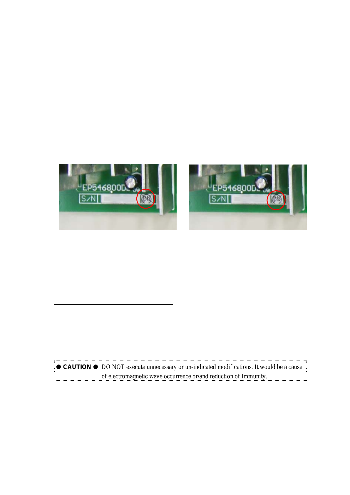
Use the label shown above for products
containing only RoHS compliant mounted
components that are soldered using lead-free
solder
Use the label shown above for products that
contain some RoHS compliant mounted
components that are soldered using lead-free
solder.
1-15 EMC and EMI
EMC (Electro-Magnetic Compatibility):
In order to apply EMC standard, following two Electromagnetic interference must have balance and
compatibility.
EMI (Electro Magnetic interferences): An interferences generated from electronic and electrical
equipment.
Immunity: Tolerance against external Electromagnetic interferences.
CAUTION DO NOT execute unnecessary or un-indicated modifications. It would be a cause
of electromagnetic wave occurrence or/and reduction of Immunity.
1 - 7
MN2-2075 Rev.0
Chapter 1 Introduction
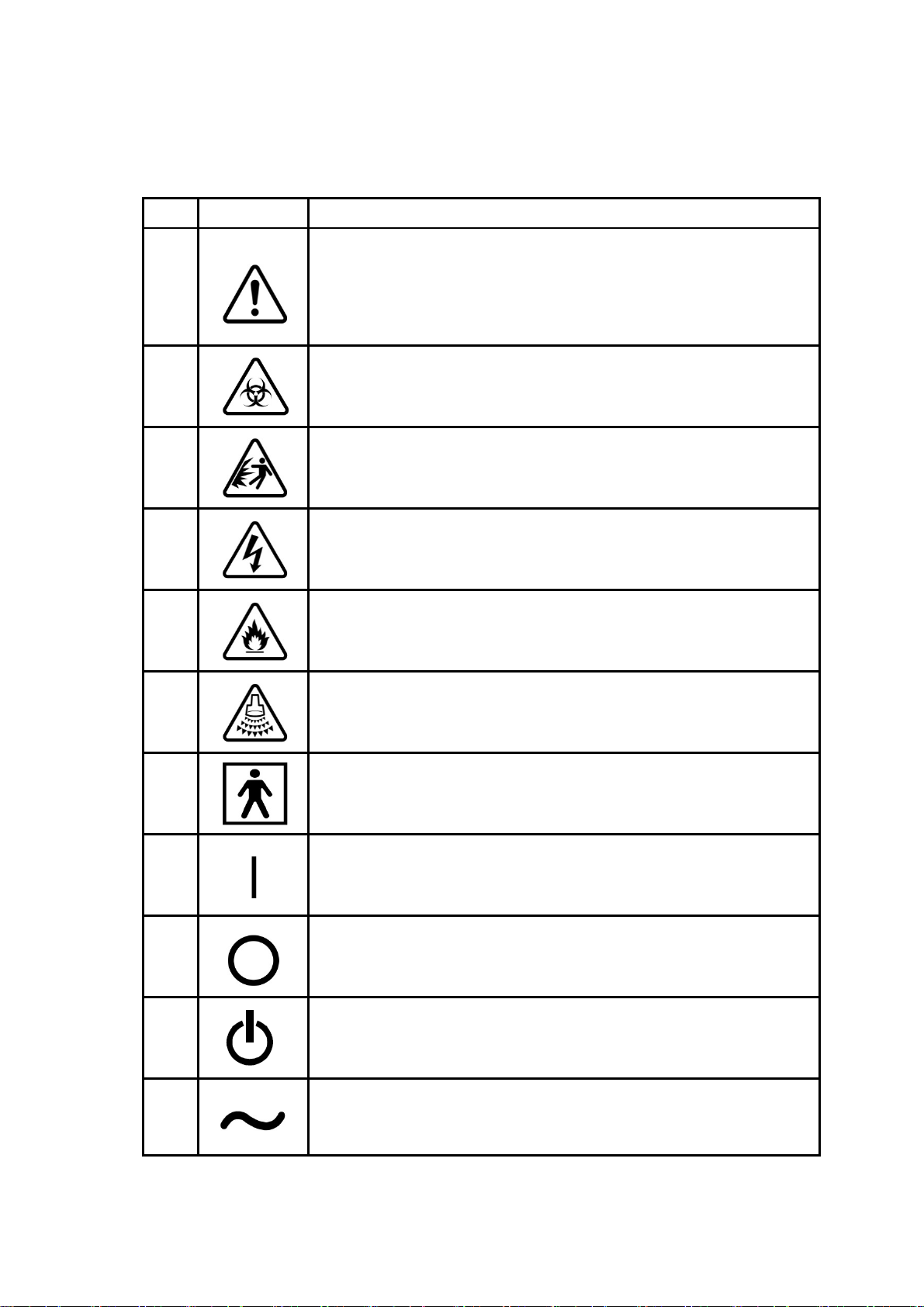
1-16 System Symbols
Symbols used by Aloka are described below, together with reference to IEC publication(s).
No. Symbol Meaning
1
2
Danger
Carefully read the pertinent items in the operation manual, and handle the
equipment with great care.
ANSI standard Z535.3
IEC60601-1, Attached table D
BS 5378 PART1, Appendix A
Biohazard
ANSI standard Z535.3
ISO7000 No.0659
BS 5378 PART1, Appendix A
3
4
5
6
7
8
Be careful of explosion
Be careful of electric shock
ANSI standard Z535.3
BS 5378 PART1, Appendix A
Be careful of fire
BS 5378 PART1, Appendix A
Be careful of acoustic power
Type BF applied part
IEC60601-1, Attached table D
Indicates the ON position of the switch.
IEC60417-5007
9
10
11
Indicates the OFF position of the switch.
IEC60417-5008
Indicates the STAND BY position of the switch.
IEC60417-5009
Alternating current
IEC60417-5032
1 - 8

No. Symbol Meaning
MN2-2075 Rev.0
Chapter 1 Introduction
12
13
14
Potential equalization terminal
IEC60417-5021
Protected against the effects of continuance immersion in water
Labeled on Foot Switch MP-2345B, MP-2614B
IEC60529
Electrostatic discharge (ESD) symbol:
Follow the ESD guide line
1 - 9

MN2-2075 Rev.0
Chapter 1 Introduction
ank Page)
(Bl
1 - 10

Chapter 2
SERVICE PROCESS
APPENDIX


MN2-2075 Rev.0
Chapter 2 Service Process
2-1 Repair work on the description of Service Manual
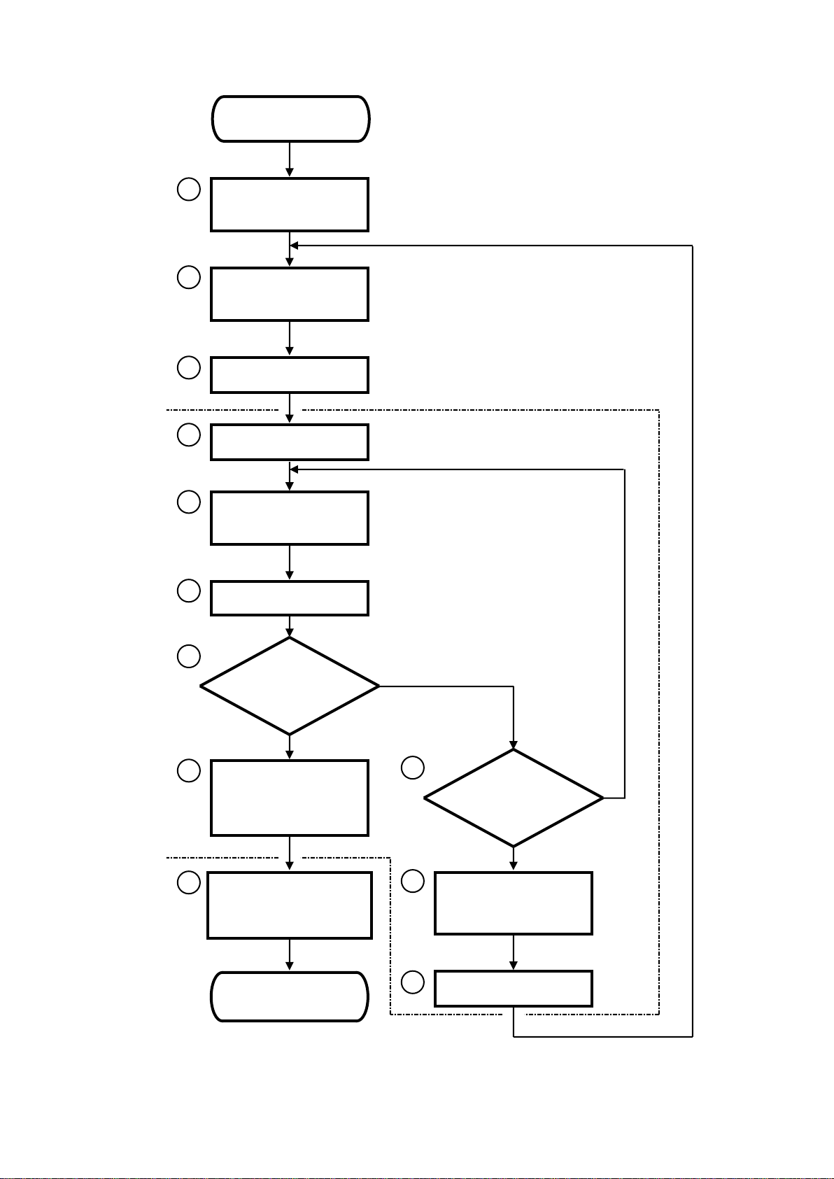
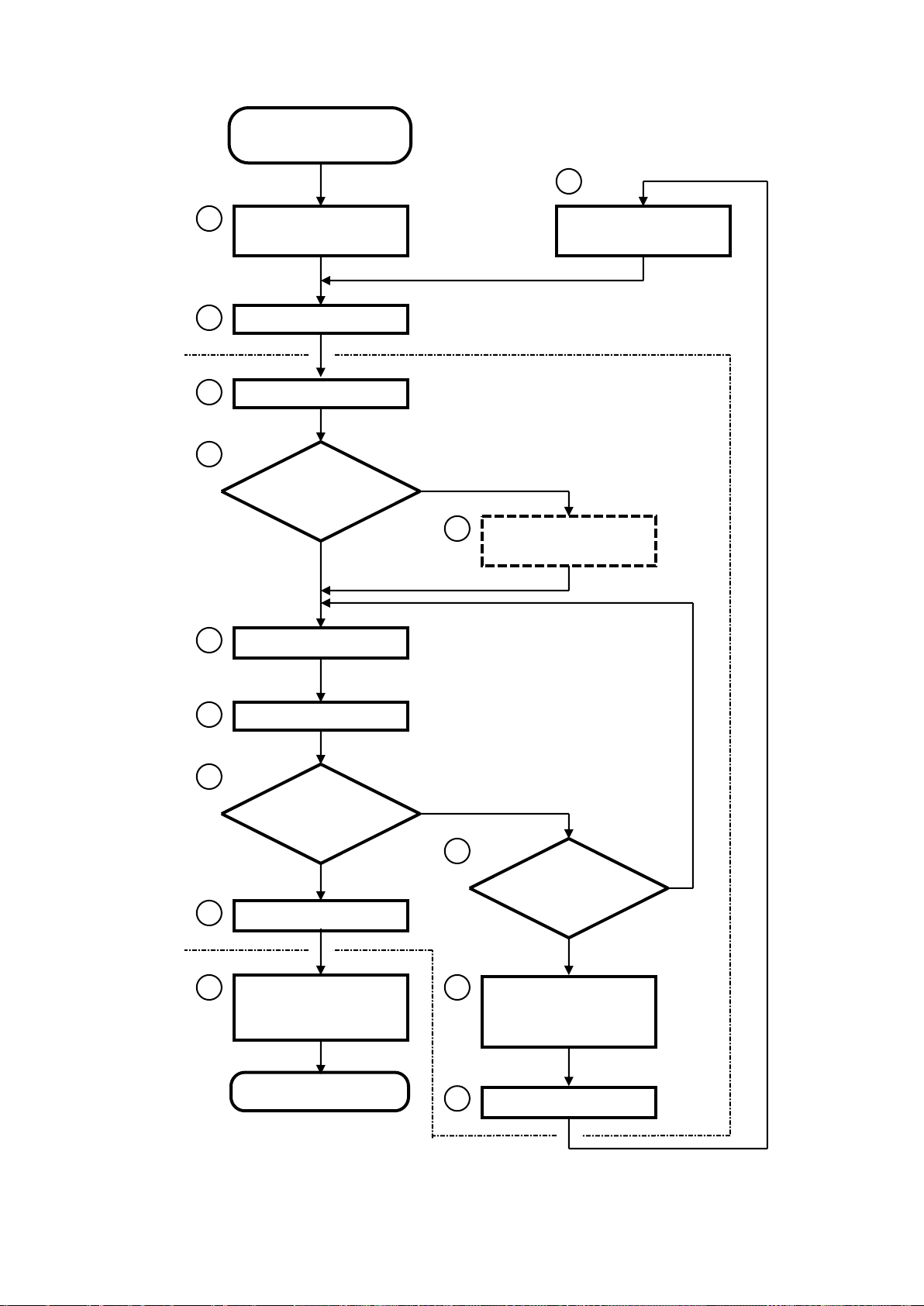
The typical processes for the repair work are shown as the Flow Chart on the next page. Do the repair
work according to this procedure. In the case of modification of the Technical Bulletin, Technical Notes
or Upgrade Kit, see the next item 2-2.
Each procedures of flow chart are numbered to refer its detail shown from page 2-3. Fur thermore, the
Flow Chart and its explanation show the time when each section of service manual are required on
repair work. This is a guide for the usage of service manual.
The service manual is very important for the repair work, especially readjustment and performance
check after completion of repair work. This is to keep the safety and quality of equipment. If you make
them, you have to describe that the treatment has been done according to the applied section of service
manual, on the repair report or the like.
The circled numbers shown in the Flow Chart on next page are corresponded to the procedure number
shown from page 2-3.
2 - 1
MN2-2075 Rev.0
At your site
At Customer side
4 3 2 1 No
No
Yes
Yes
(START)
Present repair report
Show comments of the
the equipment
(END)
VOLUME 1 Chapter 4, 5
VOLUME 2 Chapter 1, 2, 3
VOLUME 1 Chapter 5
VOLUME 2 Chapter 5
Technical Bulletin, Technical Notes
History
VOLUME 1 Chapter 2
VOLUME 1 Chapter 1, 5
VOLUME 2 Chapter 4
VOLUME 1 Chapter 6
5 6 7 8 9
11
10
12
Chapter 2 Service Proces s
Demand of repair
Reception and
Investigation
Selection and order of
Required part(s)
Preparation
Confirmation
Repair and adjustment
Operation check
Work as normal?
Check by customer
Fill repair report
Approve by customer
Demand to repair the
defective part(s)
Repair again
prohibition to use on
Completion
Report to customer
2 - 2

MN2-2075 Rev.0
Chapter 2 Service Process
Procedure 1 Reception of repair and investigation
Accept the repair request from the customer or distributor. A t this time, the following points have to be
confirmed and checked,
• Model name/number, and serial number
• Name of customer (Hospital), address, phone number, and name of person in charge
• Configuration of the connection of peripheral devices
• Software version or the like shown on the Maintenance display (if possible)
• Detail of phenomenon appeared on the function of equipment
Make an examination what circuit may be defective as the function of equipment based on the above
information. If you need to know about the basic operation and special information for the maintenance,
refer to the following sections, or ask to the Technical Support,
♦ VOLUME 1 Chapter 4 SYSTEM OVERVIEW
♦ VOLUME 1 Chapter 5 TROUBLESHOOTING
♦ VOLUME 2 Chapter 1 SYSTEM OPERATION
♦ VOLUME 2 Chapter 2 SCHEMATICS
♦ VOLUME 2 Chapter 3 SERVICE INFORMATION
The reported phenomenon may be the original problem on the equipment. Because, refer to the
Technical Bulletin or the Technical Notes separately issued to check it whether defectiveness or not. If it
has been reported as the original problem, make a work according to the Technical Bulletin or the
Technical Notes.
* The Technical Bulletin and the Technical Notes are released for Service Engineer who has taken
appropriate training.
Procedure 2 Selection of required parts and order
If you find the doubtful circuit, order the necessary parts. Then check the delivery date and decide the
date to visit on the consultation with the customer.
For the selection and order of parts, refer to the following sections
♦ VOLUME 1 Chapter 5 TROUBLE SHOOTING
♦ VOLUME 2 Chapter 5 PARTS LIST
For the electrical parts such as UNIT, check the history information on the HISTORY of this equipment
separately issued.
* The HISTORY of this equipment is released for Service Engineer who has taken appropriate
training.
2 - 3

MN2-2075 Rev.0
Chapter 2 Service Proces s
Procedure 3 Preparation of visiting the customer
Check the required tools, measuring devices and parts to be replaced before the visiting the customer.
Then check the special information for the equipment reference with the following section,
♦ VOLUME 1 Chapter 2 SERVI CE PRO CE SS
Procedure 4 Confirmation of phenomenon
Confirm the appeared phenomenon and condition to happen it with the customer. If you don’t know
about the operation of equipment, refer to the Operation Manual attached to the equipment.
Procedure 5 Repair and readjustment
Repair the defective circuit with the brought parts. For the repair work, read the following section
carefully,
♦ VOLUME 1 Chapter 1 INTRODUCTION
♦ VOLUME 1 Chapter 2 SERVI CE PRO CE SS
And, examine the trouble reason depending on the situation with following section,
♦ VOLUME 1 Chapter 5 TROUBLESHOOTING
The electrical or mechanical readjustment may be requested depending on the replaced parts. Because,
refer to the following section after completion of repair,
♦ VOLUME 2 Chapter 4 ADJUSTMENT
Procedure 6 Operation check
Check the system behavior to keep its condition as same as before in trouble, reference with the
following section. Be sure to do according to the description because check items are depending on the
portion to be treated.
♦ VOLUME 1 Chapter 6 PERFORMANCE CHECK
2 - 4

MN2-2075 Rev.0
Chapter 2 Service Process
Procedure 7 Judgment of the operation quality
If the result of “Procedure 6” is passed to the all standards, do the next “Procedure 8”. On the other side,
if not, make a judgment of “Procedure 10”.
Procedure 8 Confirm by customer, make repair report and approve
Reconfirm the solution of trouble phenomenon with the customer. Then make a repair report and obtain
approval of customer.
The repair report shows not only the treatment but also the method of readjustment and operation check.
If they have been done according to the service manual, the followings have to be shown,
“Readjusted according to the VOLUME 2 Chapter 4 of service manual.”
“Checked according to the VOLUME 1 Chapter 6 of service manual, and passed.”
Procedure 9 Presentation of report and order to repair parts
Fill the repair report with necessary item, and present it according to the certain procedure.
If the defective parts that trouble cause included is available to use again by repair, make an order to do.
If you cannot judge whether the part can be used again or not, ask to the Technical Support.
Procedure 10 Judgment of possibility to repair again
As the result of judgment on “Procedure 7”, if the trouble is not solved, judge the possibility to make
the repair work again.
If available, return to “Procedure 5” and continue to work.
If unavailable, go to “Procedure 11”.
Procedure 11 Indication of the prohibition to use
As the result of judgment on “Procedure 10”, if you judge that it is impossible to continue the repair
work at this time, indicate that the equipment is still out of order, and also show the prohibition to use,
on the equipment.
Procedure 12 Report to the customer
Report the reason why the trouble cannot be solved to the customer. Then consult about the plan of next
repair work.
And do the same way from “Procedure 2”.
2 - 5

MN2-2075 Rev.0
Chapter 2 Service Proces s
2-2 Upgrade work on the description of Service Manual
The typical processes for the upgrade work are shown as the Flow Chart on the next page. Do the
upgrade work according to this procedure. In the case of repair work, see the previous item 2-1.
Each procedures of flow chart are numbered to refer its detail shown from page 2-8. Fur thermore, the
Flow Chart and its explanation show the time when each section of service manual are required on
upgrade work. This is a guide for the usage of service manual.
The service manual is very important for the upgrade work, especially readjustment and performance
check after completion of upgrade work. This is to keep the safety and quality of equipment.
The circled numbers shown in the Flow Chart on next page, are corresponded to the procedure number
shown from page 2-8.
2 - 6
MN2-2075 Rev.0
Yes
No
Yes
At your site
At customer site
4 3 2 1 No
No
Yes
Selection and order of
requires parts/kits
Preparation
Upgrade
Show comments of the
the equipment
Completion (END)
Technical Bulletin
VOLUME 1 Chapter 2
5 6 7 8 9
11
12
Operation Check
VOLUME 1 Chapter 6
Do the repair work,
according to item 2-1
Operation check
Installation Procedure
Installation Procedure
Check by customer
Return unnecessary
Consultation with
Technical Support
10
13
14
Report to customer
Demand of Upgrade
(START)
Chapter 2 Service Process
Technical Notes
Installation Procedure
Work as normal?
Work as normal?
parts, and report of
upgrade.
VOLUME 1 Section 3
VOLUME 1 Section 6
Can recover?
prohibition to use on
2 - 7

MN2-2075 Rev.0
Chapter 2 Service Proces s
Procedure 1 Selection of required parts / kits and order
Accept the upgrade request from the customer, distributor or person in charge of sales. At this time, the
following points have to be confirmed and checked to decide the parts and kits,
• Document name that announced the upgrade or kit requested
• Model name/number, and serial number
• Name of customer (Hospital), address, phone number, and name of person in charge
• Configuration of the connection of peripheral devices
• Software version or the like shown on the Maintenance display
Make an examination what parts or kits are required based on the above information. For the selection,
refer to the following document separately issued, or ask to the
♦ Technical Bulletin
♦ Technical Notes
To confirm the detail of upgrade, see the Installation Procedure attached with applied Technical Bulletin
or T echnical Notes.
Technical Support,
Depending on the upgrade, hardware, or software, the other upgrade may be required. Check it with
the
Technical Bulletin or Technical Notes.
Then, confirm the delivery date of required parts or kits, and decide the date to visit on the consultation
with the customer.
* The Technical Bulletin and the Technical Notes are released for Service Engineer who has taken
appropriate training.
Procedure 2 Preparation of visiting the customer
Check the required tools, measuring devices and parts or kits to be used before the visiting the customer.
Then check the special information for the equipment reference with the following section and
document,
♦ VOLUME 1 Chapter 1 INTRODUCTION
♦ VOLUME 1 Chapter 2 SERVI CE PRO CESS
♦ Technical Bulletin, Technical Notes and/or Installation Procedure
2 - 8
 Loading...