

Page 1
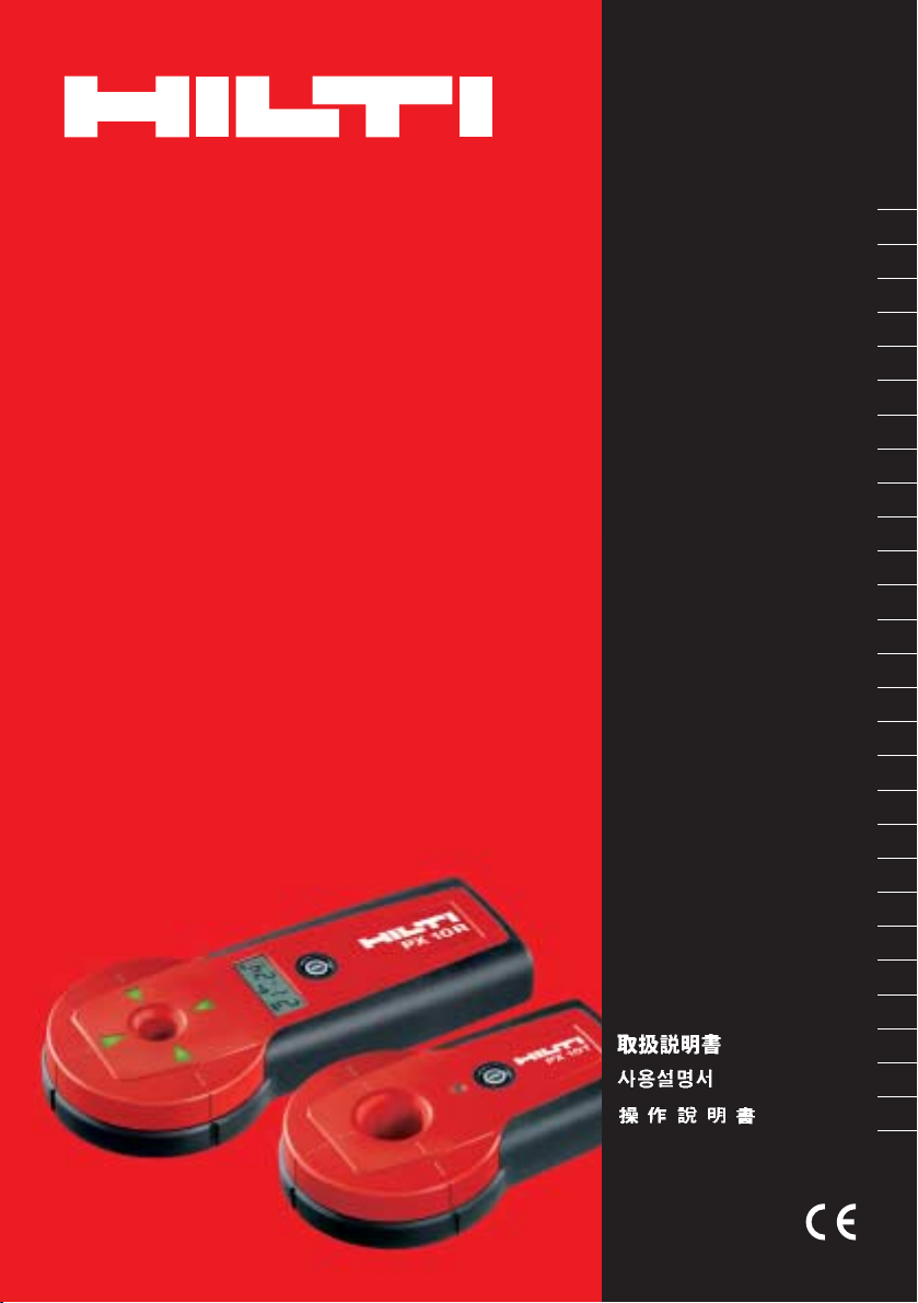
PX 10
Bedienungsanleitung de
Operating instructions en
Mode d’emploi fr
Manual de instrucciones es
Istruzioni d’uso it
Gebruiksaanwijzing nl
Brugsanvisning da
Bruksanvisning no
Bruksanvisning sv
Käyttöohje fi
Manual de instruções pt
Οδηγιες χρησεως
el
Használati utasítás hu
Návod k obsluze cs
Návod na obsluhu sk
Instrukcja obsługi pl
Upute za uporabu hr
Navodila za uporabo sl
Ръководство за обслужване bg
Инструкция по зксплуатации ru
Instrucţiuni de utilizare
ro
Lietoßanas pamåcîba lv
Instrukcija lt
Kasutusjuhend et
Kulllanma Talimat› tr
ja
ko
zh
Page 2

PX 10TPX 10T
PX 10RPX 10R
cm
9
0
°
9
0
°
4
0
°
80
°
70°
6
0°
5
0
°
40
°
1
23
4
7
+}
"±
"“
"“
"“
+#
+Ç
9
8+[ +≠ +±+“
4
4
6
5
+|
"≠
+{
"#
"Ç
+]
PXA 70
PX 10R
PX 10T
PUA 91
PUA 92
1
Page 3
PX 10 transpointer
It is essential that the operating instructions
are read before the tool is operated for the
first time.
Always keep these operating instructions
together with the tool.
Ensure that the operating instructions are
with the tool when it is g iven to other
persons.
Contents Page
1. General information 13
2. Description 14
3. Consumables 15
4. Technical data 15
5. Safety rules 16
6. Before use 17
7. Operation 17
8. Care and maintenance 20
9. Troubleshooting 21
10. Disposal 21
11. Manufacturer’s warranty - tools 22
12. FCC statement / IC statement 22
13. EC declaration of conformity 23
Operating controls and indicators 1
PX 10T transmitter
@
On/off button
;
Status indicator
=
Indentations for adhesive putty
%
Battery compartment
&
Eye for hand strap
(
PX 10R receiver
)
On/off button
+
Direction arrows
§
Battery status
/
Signal status
:
Units
·
Distance
$
Marking notch
£
Battery compartment
|
Eye for hand strap
¡
PXA 70 slope adapter
Q
Holder for PX 10R
W
Scale showing angle of measurement
E
Tilting plate
R
Marking hole
T
Marking notch
Z
PUA 91 adhesive putty
U
PUA 92 adhesive strips
I
en
1. General information
1.1 Safety notices and their meaning
CAUTION
Draws attention to a potentially dangerous situation
that could lead to slight personal injury or damage to
the equipment or other property.
NOTE
Used to draw attention to an instruction or other
useful information.
1.2 Explanation of the pictograms and other
information
Warning signs
General
warning
13
Page 4
Symbols
en
Read the
operating
instructions
before use.
Return waste
material for
recycling.
Disposal of
batteries as
municipal
wasteisnot
permissible.
1 These numbers refer to thecorresponding illustrations. The illustrations can be found on the fold-out
cover pages. Keep these pages open while studying
the operating instructions.
In these operating instructions, the designation “PX
10 transpointer” refersto the systemconsisting oftwo
components: the PX 10T (referredto as “thetransmitter”) and the PX 10R (referred to as “the receiver”).
In these operating instructions, the designation “the
tool” always refers to the PX 10 transpointer.
2. Description
Location of identification data on the tool
The type designation and serial number can be found
on the type identification plate on the PX 10T transmitter.Makeanoteofthisdatainyouroperating
instructions and always refer to it when making an
enquiry to your Hilti representative or service department.
Type:
Serial no.:
Location of identification data on the tool
The type designation and serial number can be found
onthetypeidentificationplate on the PX 10R receiver.
Makeanoteofthisdatainyouroperatinginstructions
andalwaysrefertoitwhenmakinganenquirytoyour
Hilti representative or service department.
Type:
Serial no.:
2.1 Use of the product as directed
The Hilti PX 10 transpointer is a measuring system
consisting of the PX 10T transmitter and PX 10R
receiver. It is used to bring the receiver into alignment
with the preset position of the transmitter and to
determine the distance between the two units.
The system is capable of doing this through walls and
floors. The user can thus transfer reference points
from one side of a wall to the other and, at the same
time, measure its thickness. This makes it easier to
determine at which point the drill bit will come out
on the other side of a wall or floor when drilling a
through-hole from a marked hole-starting point. The
system transfers positions from one side of a wall
or floor to the other and helps the user to determine
the required drill bit or core bit length. In conjunction
with the slope adapter, the transpointer can be used
to determine the exit point from a given reference
point and angle or, alternatively, the angle between
two given points.
14
2.2 Items supplied
1 PX 10T transmitter
1 PX 10R receiver
2 PDA 60 hand straps
2 9 volt batteries
1 PUA 91 adhesive putty
1 PUA 92 adhesive strips
1 Operating instructions
2 Manufacturer’s certificates
1 Hilti toolbox
1 PXA 70 slope adapter
10 PUA 70 markers
NOTE
Depending on the version purchased, the slope adapter and markers may not be included among the
items supplied.
Page 5
2.3 Measuring principle 2
The transmitter generates a magnetic field. T his magnetic field is capable of penetrating, bricks, wood,
concrete and steel reinforced concrete. The receiver
is calibrated insuch a way that it finds the center point
of the projected field and determines the applicable
distance by measuring the strength of the magnetic
field between the two units of the tool. The slope
adapter has been designed for use together with the
transpointer so that the magnetic field can be meas-
ured even when the receiver is placed at an angle to
the transmitter.
NOTE
The PX 10 transpointer is influenced by metal objects.
Whereas symmetrically arranged steel reinforcement
in concrete presents virtually no problem, welded
reinforcement, reinforcing mesh, flat sheet metal or
solid metal columns have a very negative effect on
the performance of the system.
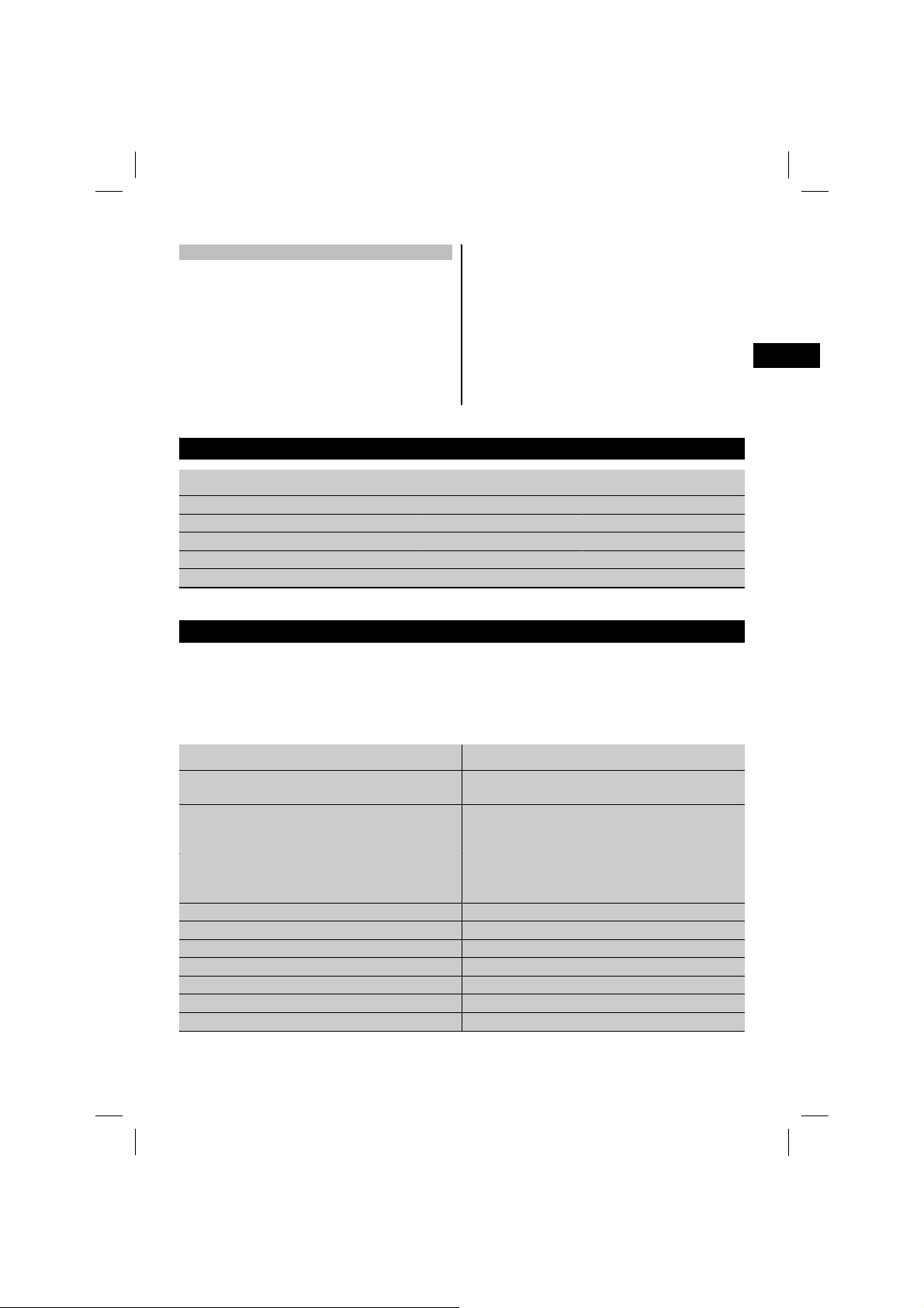
3. Consumables
Accessories Designation Item number
Adhesive putty PUA 91 273131
Adhesive strips PUA 92 273132
Hand strap PDA 60 282389
Slope adapter
Markers PUA 70 340806
PXA 70 273130
4. Technical data
NOTE
The proximity of welded reinforcement, sheet metal or metal framing to the tool may have a considerable
negative effect on its accuracy. When wall thickness measurements are made through welded reinforcing
mesh, the distance displayed is approx. 20% greater. At temperatures below -10 °C (14 °F) considerable
inaccuracy may occur with wall thicknesses greater than 50 cm (1.64 ft).
en
Technical data Values
Position-finding accuracy, standard (up to max. 1
m/3ft3in)
Position-finding accuracy, maximum (up to maximum 1 m / 3 ft 3 in, without influence by metal
objects)
Wall thickness measurement accuracy (up to
maximum1m/3ft3in,exceptwhenusingthe
slope adapter)
Measurement range (standard)
Operating temperature (PX10T,PX10R,PUA91) ‑20 to 55°C (-4 °F to +131 °F)
Operatingtemperature(PUA92) 10to40°C(+50°Fto+104°F)
Storage temperature ‑25to70°C(-13°Fto+158°F)
Power source (PX 10T, PX 10R)
Battery life (PX 10T, PX 10R) Temperature 21°C (+70°F): 17 h
Automatic cut-out, PX 10T 17 min
Temperature 21°C (+70°F), per Wall thickness 200mm:
±8 mm (7.87 in: 0.32 in)
Temperature 21°C (+70°F), per Wall thickness 200mm:
±2 mm (7.87 in: 0.08 in)
Temperature 21°C (+70°F): ±5 %
0.05to1.35m(2into4ft5in)
One 9 V battery in each
15
Page 6

Technical data Values
Automatic cut-out, PX 10R Without change in signal: 3 min, With change in
signal: 8 min
Low battery indication (PX 10T)
Low battery indication (PX 10R) Battery status indicator in display shows blinking
en
Protection class (except battery compartment) IP 56 protection against dust and water jets
Weight with battery (PX 10T) 0.24 kg (0.53 lb)
Weight with battery (PX 10R) 0.275 kg (0.61 lb)
Dimensions (PX 10T) 160 mm x 95 mm x 33 mm (6.3" x 3.8" x 1.3")
Dimensions (PX 10R) 210 mm x 95 mm x 33 mm (6.3" x 3.8" x 1.3")
Slope adapter range
Slope adapter maximum accuracy
Status indicator blinks: Remaining operating time:
Min. 2 h
frame: Remaining operating time: Min. 2 h
90 to 45° (or 0° to 45°)
±2°
5. Safety rules
5.1 General safety rules
Read and understand all instructions. Failure to
follow all instructions listed below may result in
serious personal injury.
In addition to the information relevant to safety given
in eachof the sections of these operating instructions,
the following points must be strictly observed at all
times.
5.2 Basic information concerning safety
a) Modification of the tool or tampering with its parts
is not permissible.
b) Observe the information printed in the operating
instructions concerning operation, care and main-
tenance.
c) Keep the measuring tool out of reach of children.
d) Have the tool repaired only at a Hilti service center.
e) Take the influences o f the surrounding area into
account.Donotusethetoolwherethereisarisk
of fire or explosion.
f) Check that the tool functions correctly each time
before use.
g) Operation of the tool in the proximity of pregnant
women is not permissible.
h) Avoid bringingPUA 91 into contact with the skinor
eyes. If PUA 91 comes into contact with the eyes,
rinse the eyes thoroughly with water and consult a
doctor. If PUA 91 comes intocontact with the skin,
wash the skin immediately with soap and plenty of
water.
5.3 Intended use
a) The PX 10 does not detect objects present in
a wall and therefore cannot guarantee that the
user, when drilling, will not contact electric cables,
water or gas pipes or other objects. Accordingly,
the greatest care and attention must always be
exercised while working.
5.4 Proper organization of the workplace
a) Avoid unfavorable body positions when working
on ladders or scaffolding. Make sure you work
from a safe stance and stay in balance at all times.
5.5 Electromagnetic compatibility
a) Although the tool complies with the strict require-
ments of the applicable directives, Hilti cannot
entirely rule out the possibility of the tool being
subject tointerference caused bypowerful electromagnetic radiation, leading to incorrect operation.
Check the accuracy of the tool by taking measurements by other means when working under such
conditions or if you are unsure. Likewise, Hilti
cannot rule out the possibility of interference with
other devices (e.g. aircraft navigation equipment).
16
Page 7

5.6 General safety precautions
a) Check the condition of the tool before use. If the
tool is found to be damaged, have it repaired at a
Hilti service center.
b) The user must check the accuracy of the tool
after it has been dropped or subjected to other
mechanical stresses.
c) Check that the PX 10T transmitter is well secured
when attached to a working surface.
d) Although the tool is designed for the tough con-
ditions of jobsite use, as with other measuring
instruments it should be treated with care.
6. Before use
6.1 Inserting the batteries 1
CAUTION
Do not use damaged batteries.
7. Operation
e) Although the tool is designed to prevent entry of
dampness, itshould be wiped dry eachtime before
being put away in its transport container.
5.7 Electrical
a) Keep the batteries out of reach of children.
b) Do not allow the batteries to overheat and do not
expose them to fire. The batteries may explode or
release toxic substances.
c) Do not charge the batteries.
d) Do not solder the batteries into the tool.
e) Do not discharge the batteries by short circuiting
as this may cause them to overheat and swell up.
f) Do not attempt to open the batteries and do not
subject them to excessive mechanical stress.
1. Remove the batteries from the packaging and
insert them in the tool.
2. Check that the battery terminals are positioned
correctly as shown on the underside of each tool.
en
7.1 Switching the tool off and on
Press the on/off button.
7.2 Changing the measurement units
If you wish to change the measurement unit displayed
(switch between “cm” and “inch”), proceed as follows: With the tool switched on, press and hold the
transmitter on/off button for approx. 5 sec. until the
symbol changes.
The selected measuring unit remains active each time
thetoolisswitchedon.
7.3 Setting up the transmitter 13
Use the center hole or the outer marks to align the
transmitter with the reference point and then fix it
in position. Two different adhesive aids are supplied
with the tool for this purpose.
NOTE
- It is recommended that the adhesive putty is used
wherever possible. Nevertheless, neither the adhesive
putty nor the adhesive strips are able to guarantee an
absolutely secure hold.
-Itisrecommendedthatthetoolisadditionally
secured by way of the hand strap and a nail or screw
or some similar means of mechanical attachment.
- To further increase its security, the tool can be held
by a second person.
Check to ensure that the transmitter is always set up
parallel to the surface.
7.3.1 PUA 91 adhesive putty for general use
NOTE
The adhesive putty adheres to various surfaces. The
surface should be dry and free from dust and grease.
This will ensure that best results are achieved.
NOTE
The adhesive putty can be reused. It is recommended
that the putty balls are reformed when reused.
NOTE
Theadhesiveputtycanbereuseduntilasecurehold
is no longer obtained due to the dirt and dust it has
collected.
17
Page 8

NOTE
The adhesive putty leaves marks on the surface to
which it is applied and may pull fragments away
from it when removed. If this presents a problem, an
alternative means of attachment should be employed.
The adhesive putty is used to attach the transmitter
en
to a wall or ceiling.
1. Form three balls of approximately equal size, i.e.
1 cm (0.4 in) in diameter.
NOTE Depending on the type of surface, it may
be necessary to adjust the quantity of putty used.
2. Place these in the indentations on the underside
of the transmitter.
3. Attach the transmitter securely to the wall or
ceiling by pressing it against the surface.
7.3.2 PUA 92 adhesive strips for interior use
NOTE
The adhesive strips adhere to various surfaces. The
surface must be dry and free from dust and grease.
This will ensure that best results are achieved.
NOTE
Use the adhesive strips within the ambient temperature range of 10 to 40 °C (+50 °F to +104 °F).
The adhesive strips are used to attach the transmitter
to a wall or ceiling.
1. Apply two strips(top andbottom) tothe underside
of the transmitter.
NOTE The red side should be applied to the
transmitter and the black side to the wall or
ceiling.
NOTE The end should be allowed to project about
a finger width beyond the side of the tool.
NOTE Use of two strips is recommended. It may
be necessaryto useseveral strips on certain types
of surface.
2. Press the transmitter firmly against the wall or
ceiling.
3. When removing the adhesive strips, pull them
away slowly, parallel to the surface.
NOTE The adhesive strips may pull fragments
away from the surface when removed.
7.4 Working with the receiver
CAUTION
Check that no other PX 10T transmitter is in operation
in the immediate vicinity of the transmitter you are
using.
NOTE
The receiver m ust always be positioned parallel to the
transmitter.
The signal statussymbol inthe displaylights when the
receiver is within range of the transmitter (typically
1.35 m / 4.43 ft). The direction arrows help guide the
user to the mid point of the magnetic field generated
by the transmitter. The mid point has been found
when all arrows light up. The position of the receiver
may bemarked eitherthrough the hole in thecenter of
the tool or using the external marking notches. When
at or near to the mid point, the display is illuminated
and t he distance between the devices is shown as a
minimum and maximum (not an absolute value).
7.4.1 Improving measurement accuracy in case
of influence by metal
NOTE
Do not measure in corners or immediately adjacent
to concrete walls containing steel reinforcement. In
order to avoid influence by metal objects, it is recommended that the actual measurements are made at
points offset from the reference point by a defined
distance (for example, 200 mm / 8 in).
Check that the PX 10T is secured in position and then
use the receiver to make measurements from four
sides (from above, below, right, left). Mark the points
found and then determine the geometrical center.
Where a large mass of metal is present or where
measurements are to be made close to an adjacent wall, several measurements should be made at
a known distance and the geometrical center subsequently determined, e.g. four measurements in a
square with sides 100 mm (4 in) in length.
NOTE
Workingonaroughsurfacecanbemadeeasierby
laying a sheet of nonmetallic material between the
receiver and the surface.
7.5 Working with the slope adapter
The slope adapter is used to determine the drill bit
exit point from a given entry point and angle, or to
determine the angle between two given points.
The transmitter is used as described in the section
“Setting up the transmitter”.
CAUTION
The surfaces of thewall must lieparallel to each other.
18
Page 9

NOTE
The display shows the direct distance between the
receiver and the transmitter, not the thickness of
the wall or floor. Depending on the angle and wall
thickness, angle measurements may not be possible
in some situations where the maximum range of the
tool is exceeded.
Check that the receiver is securely attached to the
slope adapter.
7.5.1 Finding a point from a given reference
point at a given angle 4
1. Set up the transmitter parallel to the surface at
the reference point.
2. Set the slope adapter to the desired angle.
3. To find the center point, rotate the slope adapter
according to the direction of slope to the point to
be found.
4. Take care to ensure that the adaptor base plate
remains parallelto theunderside ofthe transmitter
on the other side of the wall while using the
direction arrows to search for the center point,
as described in the section “Working with the
receiver”.
5. Use the marking notches or the marking hole in
the slope adapter base plate to mark the position
of the point found.
7.5.2 Finding the angle between two points 5
1. Set up the transmitter parallel to the surface at
the reference point.
2. Set up the base plate of the slope adapter on the
second reference point on the other side of the
wall.
NOTE The slope adapter should be adjusted so
that the tilting plate coincides with the direction
of inclination between the points.
3. Take care to ensurethat thebase plate of the slope
adapter remains parallel to that of the t ransmitter
at all times.
4. Move the slope adapter, keeping it perpendicular
to the angle to be determined, until both direction
indicator arrows for this axis light up. The perpendicular offset to this angle is then displayed.
5. Adjust the angle of the tilting plate carrying the
receiver until both direction arrows for the angle
axis light up.
6. Read the angle from the scale at the side.
NOTE The angle reading corresponds to the effective drilling angle and not the visually perceived
angle.
7.6 Possible applications 678
The PX 10 transpointer can be used for general
alignment tasks. The user is responsible for deciding
whether the tool achieves the accuracy required for
each application.
7.6.1 Preparing for drilling
Locating the drill bit exit point from a given entry
point (hole-starting point).
Determining the required drill bit length.
Measuring the angle between two points with the aid
of the slope adapter.
7.6.2 Reducing damage
Determining the starting point on the side from which
drillingis tobe carriedout, dependingonthe situation:
The finished surfacesof walls(cladding, tiles, etc.) are
often damaged when drilled through from the inside.
The PX 10 transpointer can be used, for example, to
transfer the hole-starting point from the inside of the
building to the outside.
This ensures that no surface-mounted objects (such
as risers, s tandpipes, etc.) are drilled into from the
other side of the wall.
7.6.3 Transferring marks
Transferring reference pointsormarksforalignment
work through walls, ceilings or floors.
7.6.4 Measuring wall thickness
Determining the thickness of walls, ceilings or floors.
7.7 Measurements to check accuracy 9
NOTE
Check the accuracy of the tool before making important measurements or if the instrument has been
dropped.
NOTE
Do not measure in corners or immediately adjacent
to concrete walls containing steel reinforcement. In
order to avoid influence by metal objects, it is recommended that the actual measurements are made at
en
19
Page 10

points offset from the reference point by a defined
distance (for example, 200 mm / 8 in).
1. Choose a wall with a thickness of approx. 50 cm
(1.64 ft) that isknown tocontain no reinforcement
and with surfaces that are known to be parallel.
2. Check that the PX 10T is secured in position
en
and then use the receiver to make measurements
from four sides (from above, below, right, left).
Mark the points found and then determine the
geometrical center.
NOTE Calibration at a Hilti service center is
necessary if a deviation of more than 6 mm (0.24
in) is found.
8. Care and maintenance
3. If you doubt whether the surfaces of the wall are
parallel, swap the positions of the transmitter and
receiver on each side of the wall and repeat the
steps described previously. Set up the transmitter
on the previously determined geometrical center.
If the second geometrical centerdoes not coincide
with theoriginal reference point, thenthesurfaces
of the wall are not parallel.
8.1 Cleaning and drying
Use only a clean, soft cloth for cleaning. If necessary,
moisten the cloth slightly with pure alcohol or a little
water.
NOTE
Do not use any other liquids as these may damage
the plastic components.
8.2 Storage
Unpack the tool i f it has become wet. The tool, its
carrying case and accessories should be cleaned and
dried (at maximum 40°C).Repack theequipment only
once it is completely dry.
Check the accuracy of the equipment before it is used
after a long period of storage or transportation.
Remove the batteries from the tool before storing it
for a long period.
NOTE
- Leaking batteries may damage the tool.
- Observe the temperature limits when storing your
equipment, especially in winter / summer if the equipment is kept inside a motor vehicle (-25°C to +70°C;
-13°Fto+158°F).
8.3 Transport
Use the Hilti toolbox orpackaging of equivalentquality
for transporting or shipping your equipment.
CAUTION
Always remove the batteries before shipping the tool.
8.4 Hilti calibration service
We recommend that the tool is checked by the Hilti
calibration service at regular intervals in order to
verify its reliability in accordance with standards and
legal requirements.
Use can be made of the Hilti calibration service
at any time, but checking at least once a year is
recommended.
The calibration service provides confirmation that the
tool is in conformance, on the day it is checked, with
the specifications given in the operating instructions.
After checking, a calibration sticker applied to the tool
and a calibrationcertificate providewritten verification
that the tool is operating in accordance with the
manufacturer’s specification.
Calibration certificates are always required by companies certified according to ISO 900x.
Your localHilti Center orrepresentative will be pleased
to provide further information.
20
Page 11

9. Troubleshooting
Fault Possible cause Remedy
The receiver is
switched on but no
signal is indicated
on the display.
The transmitter
cannot be switched
on or switches
itself off after a
short time.
The receiver cannot
be switched on or
switches itself off
after a short time.
Measurements are
inaccurate.
The direction indicator arrows flicker
at random.
The adhesive putty
doesn’t hold properly.
The transmitter has switched off automatically after 17 minutes.
The PX 10T transmitter battery is dead.
The maximum measuring range has been
exceeded.
Thesignalisscreenedbysheetmetal.
The battery is dead.
The battery is dead.
The influence exerted by metal is too
strong.
The tool is faulty.
Microphoniaeffect due to strong vibration
of the receiver.
Interference fields, e.g. caused by cordless telephones, switched-on computer
screens etc.
The adhesive putty has been used too
often.
The contact surfaces are not clean. Clean the contact surfaces.
Switch on the transmitter.
Change the battery.
Make the measurements where the wall
is less thick and then measure the offset
to the drilling position.
If possible, make the measurements at
an area where there is no sheet metal.
Change the transmitter battery.
Change the receiver battery.
Check accuracy by making measurements
“in the air” or on a wall containing no
steel reinforcement.
Have the tool checked at a Hilti service
center if the measuring tolerance is
exceeded.
Keep the receiver steady.
Switch off the source of all interference
fields.
Use new adhesive putty.
en
10. Disposal
CAUTION
Improper disposal of the equipment may have serious consequences: The burning of plastic components
generates toxic fumes which may present a health hazard. Batteries may explode if damaged or exposed to
very high temperatures, causing poisoning, burns, acid burns or environmental pollution. Careless disposal
may permit unauthorized and improper use of the equipment. This may result in serious personal injury, injury
to third parties and pollution of the environment.
21
Page 12

Most of the materials from which Hiltitools or appliances are manufactured can be recycled. The materials must
be correctly separated before they can be recycled. In many countries, Hilti has already made arrangements
for taking back old tools and appliances for recycling. Ask Hilti customer service or your Hilti representative
en
for further information.
For EC countries only
Disposal of electric tools together with municipal waste is not permissible.
In observance of European Directive 2002/96/EC on waste electrical and electronic equipment
and its implementation in accordance with national law, electric tools that have reached the end
of their life must be collected separately and returned to an environmentally compatible recycling
facility.
Dispose of the batteries in accordance with national regulations.
11. Manufacturer’s warranty - tools
Hilti warrants that the tool supplied is free of defects
in material and workmanship. T his warranty is valid
so long as the tool is operated and handled correctly,
cleaned and serviced properly and in accordance with
the Hilti Operating Instructions, and the technical
system is maintained. This means that only original
Hilti consumables, components and spare parts may
be used in the tool.
This warranty provides the free-of-charge repair or
replacement of defective parts only over the entire
lifespan of the t ool. Parts requiring repair or replacement as a result of normal wear and tear are not
covered by this warranty.
Additional claims are excluded, unless mandatory national regulations prohibit such exclusion. In
particular, Hilti is not obligated for direct, indirect, incidental or consequential damages, losses
or expenses in connection with, or by reason of, the
use of, or inability to use the tool for any purpose.
Implied warranties of merchantability or fitness for
a particular purpose a re specifically excluded.
For repair or replacement, send the tool or related
parts immediately upon discovery of the defect to
the address of the local Hilti marketing organization
provided.
This constitutes Hilti’s entire obligation with regard
to warranty and supersedes all prior or contemporaneous comments and oral or written agreements
concerning warranties.
12. FCC statement / IC statement
CAUTION
This equipment has been tested and found to comply
with the limits for a class B digital device, pursuant
to part 15 of the FCC rules. These limits are designed
to provide reasonable protection against harmful interference in a residential installation. This equipment
22
generates, uses, and can radiate radiofrequency energy and, if not installed and used in accordance with
the instructions, may cause harmful interference to
radio communications.
Page 13

However, there is no guarantee that interference will
not occur in a particular installation. If this equipment
does cause harmful interference to radio or television
reception, which can be determined by turning the
equipment on and off, the user is encouraged to try
to correct the interference by one or more of the
following measures:
- Re-orient or re-locate the receiving antenna.
- Increase the distance between the equipment and
receiver.
- Connect the equipment to an outlet on a circuit
different from that to which the receiveris connected.
2) this device must accept any interference received,
including interference that may cause undesired operation.
This device complies with the requirements defined
in RSS-210 of IC.
Operation is subject to the following two conditions:
1) this device may not cause harmful interference,
and
2) this device must accept any interference received,
including interference that may cause undesired operation.
en
- Consult the dealer or an experienced TV/radio technician for assistance.
NOTE
Changes or modifications not expressly approved by
the party responsible for compliance could void the
user’s authority to operate the equipment.
This device complies with part 15 of the FCC Rules.
Operation is subject to the following two conditions:
1) this device may not cause harmful interference,
and
13. EC declaration of conformity
Designation: Transpointer
Type: PX 10
Year of design:
We declare, on our sole responsibility, that this
product complies with the following directives and
standards: EN 300 330‑2, EN 301 489‑3 V1.4.1,
EN 60950‑1:2001 / IEC 60950‑1:2001.
2006
Made in Germany
Hilti = registered trademark of Hilti Corporation, Schaan, LI
This device complies with Part 15 of
the FCC Rules. Operation is subject
to the following two conditions: (1)
this device may not cause harmful interference, and, (2)
this device must accept any interference received,
including interference that may cause undesired operation.
Made in Germany
Hilti = registered trademark of Hilti Corporation, Schaan, LI
This device complies with Part 15 of
the FCC Rules. Operation is sudject
to the following two conditions: (1)
this device may not cause harmful interference, and, (2)
this device must accept any interference received,
including interference that may cause undesired operation.
PX 10 T
Power: 9V nominal / 30mA
Serial No.:
Manufact.:
Item No.:
FCC ID:SDL-PX1XTR1
IC: 5228A-PX1XR1
N4025
PX 10 R
Power: 9V nominal / 35mA
Serial No.:
Manufact.:
Item No.:
IC: 5228A-PX1XR1
N4025
319973
319974
Hilti Corporation
Matthias Gillner Dr. Heinz‑Joachim Schneider
Head BU Measuring Systems Executive Vice President
BU Measuring Systems Business Area Electric
03 2006 03 2006
Tools & Accessories
23
Page 14

2
PX 10R
PX 10T
3
90˚
PX 10R
PX 10R
PX 10TPX 10T
90˚
4
4
0
50
6
0
70
80
90
a = ?
PX 10T
PX 10R
6
4
0
5
0
6
0
7
0
80
9
0
8
4
0
50
6
0
70
8
0
9
0
70˚
PX 10T
PX 10R
?
5
7
4
0
50
6
0
70
80
90
PX 10RPX 10T
Page 15

500 m
m
[
1.64 ft
]
1
500 mm
[
1.64 ft
]
500 mm
[
1.64 ft
]
500 mm
[
1.64 ft
]
2
3
1
1
3
3
2
2
4
4
4
max. 6 mm
[
max. 0.24 inc
h
]
9
Page 16

*319931*
319931
Hilti Corporation
LI-9494 Schaan
Tel.: +423/ 2342111
Fax: +423 /234 2965
www.hilti.com
Hilti = registered trademark of Hilti Corp., Schaan W 3155 0506 00-Pos. 1 1 Printed in Liechtenstein © 2006
Right of technical and programme changes reserved S. E. & O.
319931 / B
 Loading...