

Page 1

Access Controller
Quick Start Guide
Page 2

DS-K2600 Series Access Controller
i
Quick Start Guide
COPYRIGHT © 2017 Hangzhou Hikvision Digital Technology Co., Ltd.
ALL RIGHTS RESERVED.
Any and all information, including, among others, wordings, pictures, graphs are the
properties of Hangzhou Hikvision Digital Technology Co., Ltd. or its subsidiaries
(hereinafter referred to be “Hikvision”). This user manual (hereinafter referred to
be “the Manual”) cannot be reproduced, changed, translated, or distributed,
partially or wholly, by any means, without the prior written permission of Hikvision.
Unless otherwise stipulated, Hikvision does not make any warranties, guarantees or
representations, express or implied, regarding to the Manual.
About this Manual
This Manual is applicable to Access Controller
Product Name
Serials
Access Controller
DS-K2601 Serials Access Controller
DS-K2602 Serials Access Controller
DS-K2604 Serials Access Controller
The Manual includes instructions for using and managing the product. Pictures,
charts, images and all other information hereinafter are for description and
explanation only. The information contained in the Manual is subject to change,
without notice, due to firmware updates or other reasons. Please find the latest
version in the company website (http://overseas.hikvision.com/en/).
Please use this user manual under the guidance of professionals.
Trademarks Acknowledgement
and other Hikvision’s trademarks and logos are the properties of
Hikvision in various jurisdictions. Other trademarks and logos mentioned below are
the properties of their respective owners.
Page 3

DS-K2600 Series Access Controller
ii
Legal Disclaimer
TO THE MAXIMUM EXTENT PERMITTED BY APPLICABLE LAW, THE PRODUCT
DESCRIBED, WITH ITS HARDWARE, SOFTWARE AND FIRMWARE, IS PROVIDED “AS
IS”, WITH ALL FAULTS AND ERRORS, AND HIKVISION MAKES NO WARRANTIES,
EXPRESS OR IMPLIED, INCLUDING WITHOUT LIMITATION, MERCHANTABILITY,
SATISFACTORY QUALITY, FITNESS FOR A PARTICULAR PURPOSE, AND
NON-INFRINGEMENT OF THIRD PARTY. IN NO EVENT WILL HIKVISION, ITS
DIRECTORS, OFFICERS, EMPLOYEES, OR AGENTS BE LIABLE TO YOU FOR ANY
SPECIAL, CONSEQUENTIAL, INCIDENTAL, OR INDIRECT DAMAGES, INCLUDING,
AMONG OTHERS, DAMAGES FOR LOSS OF BUSINESS PROFITS, BUSINESS
INTERRUPTION, OR LOSS OF DATA OR DOCUMENTATION, IN CONNECTION WITH
THE USE OF THIS PRODUCT, EVEN IF HIKVISION HAS BEEN ADVISED OF THE
POSSIBILITY OF SUCH DAMAGES.
REGARDING TO THE PRODUCT WITH INTERNET ACCESS, THE USE OF PRODUCT
SHALL BE WHOLLY AT YOUR OWN RISKS. HIKVISION SHALL NOT TAKE ANY
RESPONSIBILITES FOR ABNORMAL OPERATION, PRIVACY LEAKAGE OR OTHER
DAMAGES RESULTING FROM CYBER ATTACK, HACKER ATTACK, VIRUS INSPECTION,
OR OTHER INTERNET SECURITY RISKS; HOWEVER, HIKVISION WILL PROVIDE TIMELY
TECHNICAL SUPPORT IF REQUIRED.
SURVEILLANCE LAWS VARY BY JURISDICTION. PLEASE CHECK ALL RELEVANT LAWS
IN YOUR JURISDICTION BEFORE USING THIS PRODUCT IN ORDER TO ENSURE THAT
YOUR USE CONFORMS THE APPLICABLE LAW. HIKVISION SHALL NOT BE LIABLE IN
THE EVENT THAT THIS PRODUCT IS USED WITH ILLEGITIMATE PURPOSES.
IN THE EVENT OF ANY CONFLICTS BETWEEN THIS MANUAL AND THE APPLICABLE
LAW, THE LATER PREVAILS.
0101011060901
Page 4

DS-K2600 Series Access Controller
iii
Regulatory Information
FCC Information
Please take attention that changes or modification not expressly approved by
the party responsible for compliance could void the user’s authority to operate
the equipment.
FCC compliance: This equipment has been tested and found to comply with the
limits for a Class B digital device, pursuant to part 15 of the FCC Rules. These
limits are designed to provide reasonable protection against harmful
interference in a residential installation. This equipment generates, uses and
can radiate radio frequency energy and, if not installed and used in accordance
with the instructions, may cause harmful interference to radio communications.
However, there is no guarantee that interference will not occur in a particular
installation. If this equipment does cause harmful interference to radio or
television reception, which can be determined by turning the equipment off
and on, the user is encouraged to try to correct the interference by one or more
of the following measures:
—Reorient or relocate the receiving antenna.
—Increase the separation between the equipment and receiver.
—Connect the equipment into an outlet on a circuit different from that to
which the receiver is connected.
—Consult the dealer or an experienced radio/TV technician for help.
FCC Conditions
This device complies with part 15 of the FCC Rules. Operation is subject to the
following two conditions:
1. This device may not cause harmful interference.
Page 5
DS-K2600 Series Access Controller
iv
2. This device must accept any interference received, including interference
that may cause undesired operation.
EU Conformity Statement
This product and - if applicable - the supplied accessories
too are marked with "CE" and comply therefore with the
applicable harmonized European standards listed under the
R&TTE Directive 1999/5/EC, the EMC Directive 2014/30/EU,
the LVD Directive 2014/35/EU, the RoHS Directive 2011/65/EU.
2012/19/EU (WEEE directive): Products marked with this
symbol cannot be disposed of as unsorted municipal waste
in the European Union. For proper recycling, return this
product to your local supplier upon the purchase of
equivalent new equipment, or dispose of it at designated
collection points. For more information see:
www.recyclethis.info.
2006/66/EC (battery directive): This product contains a
battery that cannot be disposed of as unsorted municipal
waste in the European Union. See the product
documentation for specific battery information. The battery
is marked with this symbol, which may include lettering to
indicate cadmium (Cd), lead (Pb), or mercury (Hg). For
proper recycling, return the battery to your supplier or to a designated
collection point. For more information see: www.recyclethis.info.
Industry Canada ICES-003 Compliance
This device meets the CAN ICES-3 (B)/NMB-3(B) standards requirements.
Page 6
DS-K2600 Series Access Controller
v
Preventive and Cautionary Tips
Before connecting and operating your device, please be advised of the
following tips:
• Ensure unit is installed in a well-ventilated, dust-free environment.
• Keep all liquids away from the device.
• Ensure environmental conditions meet factory specifications.
• Ensure unit is properly secured to a rack or shelf. Major shocks or jolts to the unit as a
result of dropping it may cause damage to the sensitive electronics within the unit.
• Use the device in conjunction with an UPS if possible.
• Power down the unit before connecting and disconnecting accessories and peripherals.
• A factory recommended HDD should be used for this device.
• Improper use or replacement of the battery may result in hazard of explosion. Replace
with the same or equivalent type only. Dispose of used batteries according to the
instructions provided by the manufacturer.
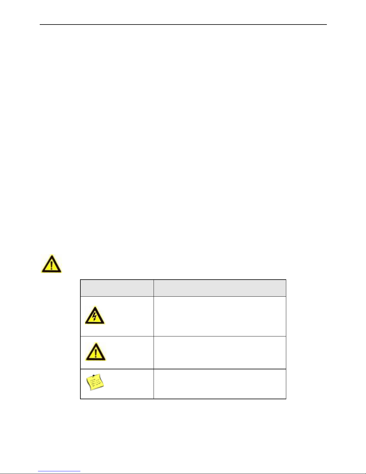
Safety Information
Signs
Description
Warning
Follow these safeguards to prevent
serious injury or death.
Note
Follow these precautions to prevent
potential injury or material damage.
Tips
The additional information as a
complimentary of the contents.
Page 7

DS-K2600 Series Access Controller
vi
Warnings:
Please adopt the power adapter from the legitimate factory which can meet the safety extra
low voltage (SELV) standard.
Do not install, wiring, or uninstall when the power is still on.
To reduce the risk of fire or electrical shock, do not expose this product to rain or moisture.
This installation should be made by a qualified service person and should conform to all the
local codes.
If the product does not work properly, please contact your dealer or the nearest service
center. Never attempt to disassemble the camera yourself. (We shall not assume any
responsibility for problems caused by unauthorized repair or maintenance.)
Note:
Please do not drop the objects on hard surface, and keep the equipment from the magnetic
field. Avoid install the equipment to the vibrated or vulnerable places.
Please do not install the device in the extreme temperature (higher than 65℃ or lower than
-20℃)
Keep ventilation.
Do not operate in humid environment.
Do not operate in explosive environment.
Keep the device clean and dry.
Avoid bare electrical wire.
Page 8

DS-K2600 Series Access Controller
1
Table of Contents
1 Product Description ............................................................................................ 3
1.1 Overview .......................................................................................................................... 3
1.2 Main Feature ................................................................................................................... 3
2 Appearance ........................................................................................................ 5
2.1 Component Description ................................................................................................... 5
2.1.1 Access Controller Component Schematic Diagram ................................................... 5
3 Terminal Connection ........................................................................................... 7
3.1 Terminals Description ...................................................................................................... 7
3.1.1 DS-K2601Terminal Description .................................................................................. 7
3.1.2 DS-K2602Terminal Description ................................................................................ 11
3.1.3 DS-K2604 Terminal Description ............................................................................... 16
4 Card Reader Installation ................................................................................... 22
4.1 External Terminal ........................................................................................................... 22
4.1.1 DS-K2601 External Terminals .................................................................................. 22
4.1.2 DS-K2602 External Terminals .................................................................................. 22
4.1.3 DS-K2604 External Terminals .................................................................................. 22
4.2 Card Reader Installation ................................................................................................ 23
4.2.4 The Connection of Wiegand Card Reader ............................................................... 23
4.2.5 RS485 Card Reader Connection ............................................................................... 24
4.3 Installing E-Lock ............................................................................................................. 25
4.3.1 Installation of Cathode Lock .................................................................................... 25
4.3.2 Installation of Anode Lock ....................................................................................... 25
4.4 Connecting the External Alarm Device .......................................................................... 26
4.5 Door Button Wiring Diagram ......................................................................................... 26
4.6 The Connection of Magnetics Detection ....................................................................... 27
4.7 Connecting Power Supply .............................................................................................. 27
Page 9

DS-K2600 Series Access Controller
2
4.8 Arming Region Input Terminal ....................................................................................... 28
4.8.1 Connecting Normally Open Detector ...................................................................... 28
4.8.2 Connecting Normally Closed Detector .................................................................... 28
4.9 Fire Alarm Module Wiring ............................................................................................. 29
5 Settings ............................................................................................................ 30
5.1 Initializing the Hardware................................................................................................ 30
5.2 Relay Input NO/NC ........................................................................................................ 30
5.2.1 Lock Relay Output ................................................................................................... 30
5.2.2 Alarm Relay Output Status ...................................................................................... 31
6 Activating Device .............................................................................................. 37
6.1 Activation via SADP Software ........................................................................................ 37
6.2 Activation via Client Software ........................................................................................ 39
Page 10

DS-K2600 Series Access Controller
3
1 Product Description
1.1 Overview
DS-K2600 is a powerful and stable access controller, using the logical architecture design.
DS-K2600 is designed with TCP/IP network interface and its signal processed with special
encryption and can be run offline. Anti-tampering function is also supported.
1.2 Main Feature
The access controller is equipped with 32-bit high-speed processor
Supports TCP/IP and GPRS network communication, Ehome accessing. The
communication data is specially encrypted to relieve the concern of privacy leak
Support recognition and storage of card number with maximum length of 20
The access controller can store 100 thousand legal cards (97 thousand normal
cards and 3 thousand visitor cards) and 300 thousand card swiping records
Supports multi-door interlock function, anti-passback function, multi-card function,
first card open function, super card and super password function, M1 card
encryption, online upgrade function and remote control of the doors
Supports tamper-proof alarm for card reader, alarm for door not secured, force
opening door alarm, alarm for door opening timeout, duress card and code alarm,
blacklist alarm and alarm for illegal card swiping attempts reaching the limit
The alarm input of controller supports short circuit protection function and
cut-proof function
Multiple event upload methods: channel, center group, and listening
50 event and card linkages
IP address conflict detection
Cross-controller anti-passing back function (For cross-controller anti-passing back
based on card, wire the card reader with RS-485. For cross-controller anti-passing
back based on network, connect the server and device properly. Up to 5000 cards’
Page 11

DS-K2600 Series Access Controller
4
swiping records can be stored in the selected server.) and inner-device
anti-pass-back function
Supports RS485 interface and Wiegand interface for accessing card reader. RS485
interface adopts dual-interface design and supports loop breakpoint detection and
redundancy function; Wiegand interface supports W26, W34 and is seamlessly
compatible with third-party card reader with Wiegand interface
Supports various card types as normal/ disabled/ blacklist/ patrol/ guest/ duress/
super card, etc.
Various indicators to show different status
Supports time synchronization via NTP, manual or automatic method
Supports record storage function when it is offline and insufficient storage space
storage alarm function
The access controller has backup battery design, watchdog design and
tamper-proof function
Data can be permanently saved after the access controller is powered off.
Supports I/O linkage, and event linkage
Supports Ehome protocol, and inter-network communication
500 groups of password under the authentication mode of card and password
Page 12
DS-K2600 Series Access Controller
5
2 Appearance
2.1 Component Description
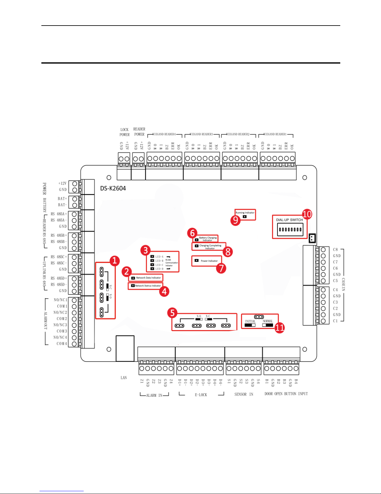
2.1.1 Access Controller Component Schematic Diagram
Take DS-K2604 as an example, the component schematic diagram is shown below.
Figure 2-1 DS-K2604 Component Schematic Diagram
Page 13

DS-K2600 Series Access Controller
6
Table 2-1 DS-K2600 Component Description
No.
Component Description
DS-K2601
DS-K2602
DS-K2604
1
Alarm Relay Output Status (NC/NO)
2
Network Data Indicator
3
RS-485 Communication Indicator
4
Network Status Indicator
5
Door Relay Output Status (NC/NO) Choice
6
Battery Charging Indicator
7
Power Indicator
8
Charging Completing Indicator
9
Running Indicator
10
Hardware Initialization and Normal Working
Choice
11
Main board dial-up switch/ Reserved
Page 14
DS-K2600 Series Access Controller
7
3 Terminal Connection
3.1 Terminals Description
3.1.1 DS-K2601Terminal Description
Figure 3-1 DS-K2601 Terminals
Page 15

DS-K2600 Series Access Controller
8
Table 3-1 DS-K2601 Terminal Description
No.
DS-K2601
A1
Lock Power
GND
Grounding
A2
+12V
Power Output of the Lock
A3
Card Reader
Power
GND
Grounding
A4
+12V
Power Output of the Head Read
A5
Wiegand
Card Reader
2
GND
Grounding
A6
W0
Wiegand Head Read Data Input Data0
A7
W1
Wiegand Head Read Data Input Data1
A8
BZ
Card Reader Buzzer Control Output
A9
ERR
Indicator of Card Reader Control Output
(Invalid Card Output)
A10
OK
Indicator of Card Reader Control Output
(Valid Card Output)
A11
Wiegand
Card Reader
1
GND
Grounding
A12
W0
Wiegand Head Read Data Input Data0
A13
W1
Wiegand Head Read Data Input Data1
A14
BZ
Card Reader Buzzer Control Output
A15
ERR
Indicator of Card Reader Control Output
(Invalid Card Output)
A16
OK
Indicator of Card Reader Control Output
(Valid Card Output)
B1
Arming
Region
Input
Z1
Arming Region Access Terminal 1 (Only for
Linkage of Alarm Relay Output)
B2
GND
Grounding
Page 16

DS-K2600 Series Access Controller
9
No.
DS-K2601
B3
Z2
Arming Region Access Terminal 2 (Only for
Linkage of Alarm Relay Output)
B4
Z3
Arming Region Access Terminal 3 (Only for
Linkage of Alarm Relay Output)
B5
GND
Grounding
B6
Z4
Arming Region Access Terminal 4 (Only for
Linkage of Alarm Relay Output)
B7
E-Lock
D1+
Door 1 Door Relay Input (Dry Contact)
B8
D1-
B9
Door
Contact
Input
S1
Door 1 Door Contact Detector Input
B10
GND
Grounding
B11
Door Open
Button
B1
Door 1 Door Open Button Input
B12
GND
Grounding
C1
Power
+12V
DC12V Cathode
C2
GND
DC12V Grounding Input
C3
Battery
BAT+
DC12V Battery Cathode
C4
BAT-
DC12V Battery Anode
C5
485 Card
Reader
RS
485A+
Card Reader RS485+ Access
C6
RS 485A-
Card Reader RS485- Access
C7
GND
Grounding
C8
RS
485B+
Card Reader RS485+
C9
RS 485B-
Card Reader RS485-
Page 17

DS-K2600 Series Access Controller
10
No.
DS-K2601
C10
GND
Grounding
C11
Access
Controller
RS485
Interface
RS
485C+
Uplink RS485+Communication
C12
RS 485C-
Uplink RS485-Communication
C13
GND
Grounding
C14
RS
485D+
Reserved
C15
RS 485D-
C16
GND
C17
Alarm
Output
NO/NC1
Alarm Relay 1 Output (Dry Contact)
C18
COM1
C19
NO/NC2
Alarm Relay 2 Output (Dry Contact)
C20
COM2
D1
Event Input
C2
Event Alarm Input 2
D2
GND
Grounding
D3
C1
Event Alarm Input 1
Page 18

DS-K2600 Series Access Controller
11
3.1.2 DS-K2602Terminal Description
Figure 3-2 DS-K2602 Terminal Description
Page 19

DS-K2600 Series Access Controller
12
Table 3-2 DS-K2602 Terminal Description
No.
DS-K2602
A1
Power for
E-Lock
GND
Grounding
A2
+12V
Power Output of the Lock
A3
Power for
Card Reader
GND
Grounding
A4
+12V
Power Output of the Head Read
A5
Wiegand
Card Reader
4
GND
Grounding
A6
W0
Wiegand Head Read Data Input Data0
A7
W1
Wiegand Head Read Data Input Data1
A8
BZ
Card Reader Buzzer Control Output
A9
ERR
Indicator of Card Reader Control Output
(Invalid Card Output)
A10
OK
Indicator of Card Reader Control Output (Valid
Card Output)
A11
Wiegand
Card Reader
3
GND
Grounding
A12
W0
Wiegand Head Read Data Input Data0
A13
W1
Wiegand Head Read Data Input Data1
A14
BZ
Card Reader Buzzer Control Output
A15
ERR
Indicator of Card Reader Control Output
(Invalid Card Output)
A16
OK
Indicator of Card Reader Control Output (Valid
Card Output)
A17
Wiegand
Card Reader
GND
Grounding
A18
W0
Wiegand Head Read Data Input Data0
Page 20

DS-K2600 Series Access Controller
13
No.
DS-K2602
A19 2 W1
Wiegand Head Read Data Input Data1
A20
BZ
Card Reader Buzzer Control Output
A21
ERR
Indicator of Card Reader Control Output
(Invalid Card Output)
A22
OK
Indicator of Card Reader Control Output (Valid
Card Output)
A23
Wiegand
Card Reader
1
GND
Grounding
A24
W0
Wiegand Head Read Data Input Data0
A25
W1
Wiegand Head Read Data Input Data1
A26
BZ
Card Reader Buzzer Control Output
A27
ERR
Indicator of Card Reader Control Output
(Invalid Card Output)
A28
OK
Indicator of Card Reader Control Output (Valid
Card Output)
B1
Arming
Region
Z1
Arming Region Access Terminal 1 (Only for
Linkage of Alarm Relay Output)
B2
GND
Grounding
B3
Z2
Arming Region Access Terminal 2 (Only for
Linkage of Alarm Relay Output)
B4
Z3
Arming Region Access Terminal 3 (Only for
Linkage of Alarm Relay Output)
B5
GND
Grounding
B6
Z4
Arming Region Access Terminal 4 (Only for
Linkage of Alarm Relay Output)
B7
E-Lock1
D1+
Door 1 Door Relay Input (Dry Contact)
Page 21

DS-K2600 Series Access Controller
14
No.
DS-K2602
B8
D1-
B9
E-Lock2
D2+
Door 2 Door Relay Input (Dry Contact)
B10
D2-
B11
Door
Magnetics
Detector
S1
Door 1 Magnetic Detector Input
B12
GND
Signal Grounding
B13
S2
Door 2 Magnetic Detector Input
B14
Door
Button
B1
Door 1 Door Button Input
B15
GND
Signal Grounding
B16
B2
Door 2 Door Button Input
C1
Power
+12V
DC12V Cathode
C2
GND
Grounding
C3
Battery
BAT+
DC12V Battery Cathode
C4
BAT-
DC12V Battery Anode
C5
Card Reader
485
Interface
RS
485A+
Card Reader RS485+ Access
C6
RS 485A-
Card Reader RS485- Access
C7
GND
Grounding
C8
RS
485B+
Card Reader RS485+
C9
RS 485B-
Card Reader RS485-
C10
GND
Grounding
C11
RS-485
Interface
RS
485C+
Uplink RS485+Communication
C12
RS 485C-
Uplink RS485-Communication
Page 22

DS-K2600 Series Access Controller
15
No.
DS-K2602
C13
GND
Grounding
C14
RS
485D+
Reserved
C15
RS 485D-
C16
GND
C17
Alarm
Output
NO/NC1
Alarm Relay 1 Output (Dry Contact)
C18
COM1
C19
NO/NC2
Alarm Relay 2 Output (Dry Contact)
C20
COM2
C21
NO/NC3
Alarm Relay 3 Output (Dry Contact)
C22
COM3
C23
NO/NC4
Alarm Relay 4 Output (Dry Contact)
C24
COM4
D1
Event Input
C4
Event Alarm Input 4
D2
GND
Grounding
D3
C3
Event Alarm Input3
D4
C2
Event Alarm Input 2
D5
GND
Grounding
D6
C1
Event Alarm Input 1
Page 23

DS-K2600 Series Access Controller
16
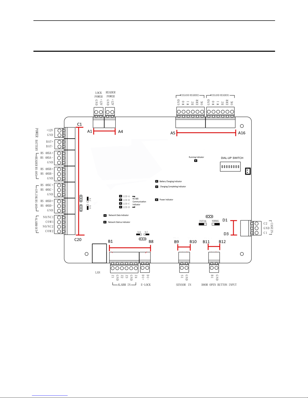
3.1.3 DS-K2604 Terminal Description
Figure 3-3 DS-K2604 Access Controller Terminals
Table 3-3 DS-K2604 Port Description
No.
DS-K2604
A1
Power
Supply of
E-Lock
GND
Grounding
A2
+12V
Power Supply of E-Lock Output
A3
Power
Supply of
Card Reader
GND
Grounding
A4
+12V
Power Supply of Card Reader Output
Page 24

DS-K2600 Series Access Controller
17
No.
DS-K2604
A5
Wiegand
Card Reader
4
GND
Grounding
A6
W0
Wiegand Card Reader Data Input Data0
A7
W1
Wiegand Card Reader Data Input Data1
A8
BZ
Buzzer of Card Reader Control Output
A9
ERR
Cresset of Card Reader Control Output
(Invalid Card Output)
A10
OK
Cresset of Card Reader Control Output (Valid
Card Output)
A11
Wiegand
Card Reader
3
GND
Grounding
A12
W0
Wiegand Card Reader Data Input Data0
A13
W1
Wiegand Card Reader Data Input Data1
A14
BZ
Buzzer of Card Reader Control Output
A15
ERR
Cresset of Card Reader Control Output
(Invalid Card Output)
A16
OK
Cresset of Card Reader Control Output (Valid
Card Output)
A17
Wiegand
Card Reader
2
GND
Grounding
A18
W0
Wiegand Card Reader Data Input Data0
A19
W1
Wiegand Card Reader Data Input Data1
A20
BZ
Buzzer of Card Reader Control Output
A21
ERR
Cresset of Card Reader Control Output
(Invalid Card Output)
A22
OK
Cresset of Card Reader Control Output (Valid
Card Output)
Page 25

DS-K2600 Series Access Controller
18
No.
DS-K2604
A23
Wiegand
Card Reader
1
GND
Grounding
A24
W0
Wiegand Card Reader Data Input Data0
A25
W1
Wiegand Card Reader Data Input Data1
A26
BZ
Buzzer of Card Reader Control Output
A27
ERR
Cresset of Card Reader Control Output
(Invalid Card Output)
A28
OK
Cresset of Card Reader Control Output (Valid
Card Output)
B1
Arming
Region
Input
Z1
Arming Region Access Terminal 1 (Only for
Linkage of Alarm Relay Output)
B2
GND
Grounding
B3
Z2
Arming Region Access Terminal 2 (Only for
Linkage of Alarm Relay Output)
B4
Z3
Arming Region Access Terminal 3 (Only for
Linkage of Alarm Relay Output)
B5
GND
Grounding
B6
Z4
Arming Region Access Terminal 4 (Only for
Linkage of Alarm Relay Output)
B7
E-Lock 1
D1+
Door 1 Door Relay Input (Dry Contact)
B8
D1-
B9
E-Lock 2
D2+
Door 2 Door Relay Input (Dry Contact)
B10
D2-
B11
E-Lock 3
D3+
Door 3 Door Relay Input (Dry Contact)
Page 26

DS-K2600 Series Access Controller
19
No.
DS-K2604
B12
D3-
B13
E-Lock 4
D4+
Door 4 Door Relay Input (Dry Contact)
B14
D4-
B15
Door
Magnetics
Input
S1
Door 1 Magnetic Detector Input
B16
GND
Signal Grounding
B17
S2
Door 2 Magnetic Detector Input
B18
S3
Door 3 Magnetic Detector Input
B19
GND
Signal Grounding
B20
S4
Door 4 Magnetic Detector Input
B21
Door Button
B1
Door 1 Door Button Input
B22
GND
Signal Grounding
B23
B2
Door 2 Door Button Input
B24
B3
Door 3 Door Button Input
B25
GND
Signal Grounding
B26
B4
Door 4 Door Button Input
C1
Power
+12V
DC12V Cathode
C2
GND
Grounding
C3
Battery
BAT+
DC12V Battery Cathode
C4
BAT-
DC12V Battery Anode
C5
Card Reader
RS485
RS
485A+
Card Reader RS485A+
C6
RS 485A-
Card Reader RS485A-
C7
GND
Grounding
Page 27

DS-K2600 Series Access Controller
20
No.
DS-K2604
C8
RS 485B+
Card Reader RS485B+
C9
RS 485B-
Card Reader RS485B-
C10
GND
Grounding
C11
Access
Controller
RS485
RS 485C+
Uplink RS485+Communication
C12
RS 485C-
Uplink RS485-Communication
C13
GND
Grounding
C14
RS
485D+
Reserved
C15
RS 485D-
C16
GND
C17
Alarm
Output
NO/NC1
Alarm Relay 1 Output (Dry Contact)
C18
COM1
C19
NO/NC2
Alarm Relay 2 Output (Dry Contact)
C20
COM2
C21
NO/NC3
Alarm Relay 3 Output (Dry Contact)
C22
COM3
C23
NO/NC4
Alarm Relay 4 Output (Dry Contact)
C24
COM4
D1
Event Input
C8
Event Alarm Input 8
D2
GND
Grounding
D3
C7
Event Alarm Input 7
D4
C6
Event Alarm Input 6
D5
GND
Grounding
Page 28

DS-K2600 Series Access Controller
21
No.
DS-K2604
D6
C5
Event Alarm Input 5
D7
C4
Event Alarm Input 4
D8
GND
Grounding
D9
C3
Event Alarm Input3
D10
C2
Event Alarm Input 2
D11
GND
Grounding
D12
C1
Event Alarm Input 1
Note:
The Alarm input hardware interface is normally open by default. So only the normally
open signal is allowed. It can be linked to the buzzer of the card reader and access
controller, and the alarm relay output and open door relay output.
Arming region alarm input is only for the alarm relay output linkage.
RS485 card ID should be set as 1to 8. For example, the ID of door 1 is 1 and 2 standing
for in and out respectively.
For single-door access controller, the Wiegand card reader 1 and 2 respectively
correspond to the entering and exiting card readers of door 1. For two-door access
controller, the Wiegand card reader 1 and 2 respectively correspond to the entering
and exiting card readers of door 1 , and the Wiegand card reader 3 and 4 respectively
correspond to the entering and exiting card readers of door 2. For single-door access
controller, the Wiegand card reader 1, 2, 3 and 4 respectively correspond to the
entering card readers of door 1, 2, 3, and 4.
Page 29

DS-K2600 Series Access Controller
22
4 Card Reader Installation
4.1 External Terminal
4.1.1 DS-K2601 External Terminals
Figure 4-1 DS-K2601 External Terminals
4.1.2 DS-K2602 External Terminals
Figure 4-2 DS-K2602 External Terminals
4.1.3 DS-K2604 External Terminals
Figure 4-3 DS-K2604 External Terminals
Page 30

DS-K2600 Series Access Controller
23
4.2 Card Reader Installation
4.2.4 The Connection of Wiegand Card Reader
Figure 4-4 Wiring diagram of Wiegand card reader
Note:
You must connect the OK/ERR/BZ, if using access controller to control the LED and
buzzer of the Wiegand card reader.
Page 31

DS-K2600 Series Access Controller
24
4.2.5 RS485 Card Reader Connection
Figure 4-5 Wiring diagram of RS485
Note:
If the card reader is installed too far away from the access controller, you can use an external
power supply.
Page 32

DS-K2600 Series Access Controller
25
4.3 Installing E-Lock
4.3.1 Installation of Cathode Lock
Figure 4-6 Wiring diagram of cathode lock
4.3.2 Installation of Anode Lock
Figure 4-7 Wiring diagram of anode lock
Page 33

DS-K2600 Series Access Controller
26
4.4 Connecting the External Alarm Device
Figure 4-8 External Alarm Device Connection
4.5 Door Button Wiring Diagram
Figure 4-9 Power Button Connection
Page 34

DS-K2600 Series Access Controller
27
4.6 The Connection of Magnetics Detection
Figure 4-10 Magnetics Connection
4.7 Connecting Power Supply
Figure 4-11 Power Supply Connection
Page 35

DS-K2600 Series Access Controller
28
4.8 Arming Region Input Terminal
4.8.1 Connecting Normally Open Detector
Figure 4-12 Normally Open Status
4.8.2 Connecting Normally Closed Detector
Figure 4-13 Normally Closed Status
Page 36

DS-K2600 Series Access Controller
29
4.9 Fire Alarm Module Wiring
Figure 4-14 Fire Alarm Module Wiring
Page 37

DS-K2600 Series Access Controller
30
5 Settings
5.1 Initializing the Hardware
Option 1:
Steps:
1. Remove the jumper cap from the Normal terminal.
2. Disconnect the power and restart the access controller. The controller buzzer buzzes a
long beep.
3. When the beep stopped, plug the jumper cap back to Normal.
Option 2:
Steps:
1. Jump the jumper cap from Normal to Initial.
2. Disconnect the power and restart the access controller. The controller buzzer buzzes a
long beep.
3. When the beep stopped, jump the jumper cap back to Normal.
Figure 5-1 Initialization Dial-up
Note:
The initializing of the hardware will restore all the parameters to the default
setting and all the device events are wiping out.
5.2 Relay Input NO/NC
5.2.1 Lock Relay Output
Lock Relay Normally Open Status
Page 38

DS-K2600 Series Access Controller
31
Figure 5-2 Normally Open Status
Lock Relay Normally Closed Status
Figure 5-3 Normally Closed Status
5.2.2 Alarm Relay Output Status
Alarm Relay Output Normally Open
Figure 5-4 Alarm Relay Output Normally Open
Alarm Relay Output Normally Closed
Page 39

DS-K2600 Series Access Controller
32
Figure 5-5 Normally Closed Status
Work Flow of Software
For detailed information, please see the user manual of the client software.
Refer to the following work flow:
Figure 5-6 Software Client Work Flow
Page 40

DS-K2600 Series Access Controller
37
6 Activating Device
Purpose:
You are required to activate the control panel first before you can use the control panel.
Activation via SADP, and Activation via client software are supported.
6.1 Activation via SADP Software
SADP software is used for detecting the online device, activating the device, and resetting
the password.
Get the SADP software from the supplied disk or the official website, and install the SADP
according to the prompts. Follow the steps to activate the control panel.
Steps:
1. Run the SADP software to search the online devices.
2. Check the device status from the device list, and select an inactive device.
Figure 1-1 SADP Interface
3. Create a password and input the password in the password field, and confirm the
password.
Page 41

DS-K2600 Series Access Controller
38
STRONG PASSWORD RECOMMENDED– We highly recommend you create a
strong password of your own choosing (using a minimum of 8 characters,
including upper case letters, lower case letters, numbers, and special characters)
in order to increase the security of your product. And we recommend you reset
your password regularly, especially in the high security system, resetting the
password monthly or weekly can better protect your product.
4. Click Activate to activate the device.
5. Check the activated device. You can change the device IP address to the same network
segment with your computer by either modifying the IP address manually or checking
the checkbox of Enable DHCP.
Figure 1-2 Modify Network Parameters Interface
6. Input the password and click the Modify button to activate your IP address modification.
Page 42

DS-K2600 Series Access Controller
39
6.2 Activation via Client Software
The client software is versatile video management software for multiple kinds of devices.
Get the client software from the supplied disk or the official website, and install the software
according to the prompts. Follow the steps to activate the control panel.
Steps:
1. Run the client software and the control panel of the software pops up, as shown in the
figure below.
Figure 1-3 Control Panel Interface
2. Click the Device Management to enter the Device Management interface.
3. Check the device status from the device list, and select an inactive device.
Page 43

DS-K2600 Series Access Controller
40
Figure 1-4 List Selecting Interface
4. Click the Activate button to pop up the Activation interface.
5. In the pop-up window, create a password in the password field, and confirm the
password.
STRONG PASSWORD RECOMMENDED– We highly recommend you create a
strong password of your own choosing (using a minimum of 8 characters,
including upper case letters, lower case letters, numbers, and special characters)
in order to increase the security of your product. And we recommend you reset
your password regularly, especially in the high security system, resetting the
password monthly or weekly can better protect your product.
Figure 1-5 Password Interface
6. Click OK button to activate.
7. Click the Modify Netinfor button to pop up the Network Parameter Modification
interface.
8. Change the device IP address to the same network segment with your computer by
either modifying the IP address manually.
9. Input the password and click the OK button to save the settings.
Page 44

DS-K2600 Series Access Controller
41
UD05848B
 Loading...