

Page 1

(IP) Network Camera
User Manual
Page 2

IP Network Camera User Manual
Copyright 2018−2019 Hikvision USA Inc. and Hikvision Canada Inc.
Hikvision USA Inc., 18639 Railroad St., City of Industry, CA 91748, USA
Hikvision Canada, 4848 rue Levy, Saint Laurent, Quebec, Canada, H4R 2P1
Telephone: +1-909-895-0400 • Toll Free in USA: +1-866-200-6690
E-Mail: sales.usa@hikvision.com • www.hikvision.com
ALL RIGHTS RESERVED.
Any and all information, including, among others, wordings, pictures, graphs are the properties of Hangzhou Hikvision Digital Technology Co., Ltd. or its
subsidiaries (hereinafter referred to be “Hikvision”). This user manual (hereinafter referred to be “the Manual”) cannot be reproduced, changed, translated, or
distributed, partially or wholly, by any means, without the prior written permission of Hikvision. Unless otherwise stipulated, Hikvision does not make any
warranties, guarantees or representations, express or implied, regarding to the Manual.
About this Manual: The Manual includes instructions for using and managing the product. Pictures, charts, images and all other information hereinafter are for
description and explanation only. The information contained in the Manual is subject to change, without notice, due to firmware updates or other reasons.
Please find the latest version in the company Website (http://overseas.hikvision.com/en/).
Please use this user manual under the guidance of professionals.
Manual Illustrations and Features: Graphics (screen shots, product pictures, etc.) in this document are for illustrative purposes only. Your actual product may
differ in appearance. Your product might not support all features discussed in this document.
Trademarks Acknowledgement: and other Hikvision trademarks and logos are the properties of Hikvision in various jurisdictions. Other
trademarks and logos mentioned below are the properties of their respective owners.
Legal Disclaimer
TO THE MAXIMUM EXTENT PERMITTED BY APPLICABLE LAW, THE PRODUCT DESCRIBED, WITH ITS HARDWARE, SOFTWARE AND FIRMWARE, IS PROVIDED “AS IS,” WITH ALL
FAULTS AND ERRORS, AND HIKVISION MAKES NO WARRANTIES, EXPRESS OR IMPLIED, INCLUDING WITHOUT LIMITATION, MERCHANTABILITY, SATISFACTORY QUALITY,
FITNESS FOR A PARTICULAR PURPOSE, AND NON-INFRINGEMENT OF THIRD PARTY. IN NO EVENT WILL HIKVISION, ITS DIRECTORS, OFFICERS, EMPLOYEES, OR AGENTS BE
LIABLE TO YOU FOR ANY SPECIAL, CONSEQUENTIAL, INCIDENTAL, OR INDIRECT DAMAGES, INCLUDING, AMONG OTHERS, DAMAGES FOR LOSS OF BUSINESS PROFITS,
BUSINESS INTERRUPTION, OR LOSS OF DATA OR DOCUMENTATION, IN CONNECTION WITH THE USE OF THIS PRODUCT, EVEN IF HIKVISION HAS BEEN ADVISED OF THE
POSSIBILITY OF SUCH DAMAGES.
REGARDING TO THE PRODUCT WITH INTERNET ACCESS, THE USE OF PRODUCT SHALL BE WHOLLY AT YOUR OWN RISKS. HIKVISION SHALL NOT TAKE ANY RESPONSIBILITIES
FOR ABNORMAL OPERATION, PRIVACY LEAKAGE OR OTHER DAMAGES RESULTING FROM CYBER ATTACK, HACKER ATTACK, VIRUS INSPECTION, OR OTHER INTERNET SECURITY
RISKS; HOWEVER, HIKVISION WILL PROVIDE TIMELY TECHNICAL SUPPORT IF REQUIRED.
SURVEILLANCE LAWS VARY BY JURISDICTION. PLEASE CHECK ALL RELEVANT LAWS IN YOUR JURISDICTION BEFORE USING THIS PRODUCT IN ORDER TO ENSURE THAT YOUR
USE CONFORMS TO THE APPLICABLE LAW. HIKVISION SHALL NOT BE LIABLE IN THE EVENT THAT THIS PRODUCT IS USED FOR ILLEGITIMATE PURPOSES.
IN THE EVENT OF ANY CONFLICTS BETWEEN THIS MANUAL AND THE APPLICABLE LAW, THE LATTER PREVAILS.
Regulatory Information
FCC Information: Please take attention that changes or modification not expressly approved by the party responsible for compliance could void the user’s
authority to operate the equipment.
FCC Compliance: This equipment has been tested and found to comply with the limits for a Class A digital device, pursuant to part 15 of the FCC Rules. These
limits are designed to provide reasonable protection against harmful interference when the equipment is operated in a commercial environment. This
equipment generates, uses, and can radiate radio frequency energy and, if not installed and used in accordance with the instruction manual, may cause
harmful interference to radio communications. Operation of this equipment in a residential area is likely to cause harmful interference in which case the user
will be required to correct the interference at his own expense.
FCC Conditions: This device complies with part 15 of the FCC Rules. Operation is subject to the following two conditions:
•
This device may not cause harmful interference.
•
This device must accept any interference received, including interference that may cause undesired operation.
EU Conformity Statement
This product and, if applicable, the supplied accessories too are marked with “CE” and comply therefore with the applicable harmonized European
standards listed under the EMC Directive 2014/30/EU, the LVD Directive 2014/35/EU, the RoHS Directive 2011/65/EU.
2012/19/EU (WEEE Directive): Products marked with this symbol cannot be disposed of as unsorted municipal waste in the European Union. For proper
recycling, return this product to your local supplier upon the purchase of equivalent new equipment, or dispose of it at designated collection points.
For more information see: www.recyclethis.info
2006/66/EC (Battery Directive): This product contains a battery that cannot be disposed of as unsorted municipal waste in the European Union. See the
product documentation for specific battery information. The battery is marked with this symbol, which may include lettering to indicate cadmium
(Cd), lead (Pb), or mercury (Hg). For proper recycling, return the battery to your supplier or to a designated collection point. For more information see:
www.recyclethis.info
Industry Canada ICES-003 Compliance: This device meets the CAN ICES-3 (A)/NMB-3(A) standards requirements.
Hikvision North America Privacy Policy
Last Updated: December 2018
Hikvision USA Inc. and Hikvision Canada Inc. and its affiliates (collectively “HIKVISION”) provide the following services for use in conjunction with various HIKVISION
Internet-connected products (“Products”): a HIKVISION user Website and user accounts that may be accessed at
us.hikvision.com,
ca.hikvision.com,
https://distributors-us.hikvision.com/,
https://distributors-us.hikvision.com/guestLogin.htm,
https://ezviz-rma.hikvision.com/,
https://order-na.hikvision.com,
and all associated sites connected with us.hikvision.com (the “Website”); and any services available on the Website, Web Apps, and Mobile Apps (“Available
UM IP Network Camera 071619NA 2
Page 3

IP Network Camera User Manual
Services”). The term “HIKVISION Services” means the Website and Available Services.
This Privacy Policy explains how HIKVISION handles the collection, storage, and disclosure of information, including personal information, regarding our
HIKVISION Services. It also applies to any information we collect from the operation and use of Products we sell while connected to the HIKVISION Services (the
“Products), and any other HIKVISION Service that links to this Privacy Policy.
We may modify this Privacy Policy at any time, provided certain provisions of this Privacy Policy prove to be incomplete or outdated and further provided that
these changes are reasonable for you, taking into account your interests. If we make material changes to this Privacy Policy, we will notify you by the e-mail
address specified in your account or by means of notice on our Websites.
You can determine when this Privacy Policy was last revised by referring to the date it was “Last Updated” above.
What Information We Collect
In order to provide HIKVISION services to you, we will ask you to provide personal information that is necessary to provide those services to you. If you do not
provide your personal information, we may not be able to provide you with our products or services.
“Personal information” shall have the same meaning as “personal data” and shall include any information relating to an identified or identifiable natural person
(“data subject”); an identifiable person is one who can be identified, directly or indirectly, in particular by reference to an identification number or to one or
more factors specific to his physical, physiological, mental, economic, cultural, or social identity. Examples of personal information include your name,
telephone number, e-mail address, and physical address.
Personal information also includes information that alone cannot directly identify you, but with other information we have access to can identify you such as
product serial numbers, log data that automatically records information about your visit such as your browser type, domains, page views, the URL of the page
that referred you, the URL of the page you next visit, your IP address, and page navigation, unique device ID collected from Products and your mobile devices, data
from cookies, pixel tags, and Web beacons, video content files that do not contain personal visual identity information, the country and time zone of the
connected Product, geo-location, mobile phone carrier identification, and device software platform and firmware information.
How We Collect and Use Your Information
Here are some examples of the personal information we may collect and how we may use it:
•
When you create your account to use HIKVISION Services (“Account”), we will collect information including your name, phone number, and e-mail and
physical address. In addition, when you install and activate Products, we will collect certain basic information via our HIKVISION Services such as your
product name, the product’s verification code, and serial number, which are unique to the Product connected to the HIKVISION Services and associated with
your Account.
•
When you respond to our e-mails, contact our customer service, or use other customer support tools, we collect your information to provide you with
support, verify your identity with your Account profile information, and confirm your Product.
We may also use the information we collect for the following purpose:
•
send you reminders, technical notices, updates, alerts, support and administrative messages, service bulletins, and requested information; and
•
pursuant to our legitimate business interests:
˗ operate, maintain, improve, and develop our HIKVISION Services and Products;
˗ personalize your experience with our HIKVISION Services and Products;
˗ increase the safety of our HIKVISION Services and Products – for example, for user authentication, security protection, fraud detection, filing, and
backups;
˗ perform analytics and conduct customer research;
˗ communicate and provide to existing customers additional information that may be of interest to you about our products and services;
˗ manage our everyday business needs such as auditing, administration of our HIKVISION Services, forum management, fulfillment, analytics, fraud
prevention, and enforcement of our corporate reporting obligations and Terms of Service;
˗ enhance other information we have about you to help us better understand you and determine your interests; and
˗ in the context of a corporate transaction (e.g., corporate restructuring, sale or assignment of assets, merger) and to protect our rights or property, to
enforce our Terms of Service and legal notices and for the establishment, exercise, and defense of legal claims;
with your express consent to
˗ send you electronic communications in order to inform you about new products and services, unless you choose to unsubscribe;
˗ use certain non-essential cookies to better understand user behavior, in order to optimize user experience, perfect function design, and offers for
products and services from us or to provide better services;
•
meet a legal obligation, a court order or other binding decision(s); and accomplish a purpose unrelated to those described in this Privacy Policy by first
notifying you and, where required, offering you a choice as to whether or not we may use your Personal Information in this different manner.
Cookies and Other Technologies
We also use cookies, Web beacons, pixel tags, and other technologies to keep records, store your preferences, improve our advertising, and collect
information such as log data and device data. This allows us to better understand how you use our HIKVISION Services and Products, diagnose and troubleshoot
any problems you have, and otherwise administer and improve our HIKVISION Services and Products. For more information about cookies, please refer to our Use
of Cookies (https://order-na.hikvision.com/helpCenter/useOfCookies).
How We Share Your Information
HIKVISION may disclose personal information to cloud service provider, network service provider, and other service providers on the basis of non-disclosure
agreements.
The following are the limited situations where we may share personal information:
•
We share your personal information with HIKVISION affiliates, who are required to use that information in accordance with the purposes described in this
Privacy Policy.
•
We use service providers, vendors, technicians, and other third-parties to help us process, store, and protect some of your data and otherwise help us
administer our Products and HIKVISION Services effectively, provide a better user experience, process your purchases, and increase the quality of our Products
and HIKVISION Services. These third-parties are forbidden from using your personal information for non-HIKVISION purposes and are required to protect your
UM IP Network Camera 071619NA 3
Page 4

IP Network Camera User Manual
information in accordance with this Privacy Policy and applicable laws.
•
We may provide information to third-parties if we believe in good faith that we are required by mandatory law to do so. For example, to comply with legal orders
and government requests; response to a subpoena, or similar legal process, including to law enforcement agencies, regulators, and courts; to protect the
interests of our customers and users of the HIKVISION Service; to respond to claims that any content posted or displayed using the HIKVISION Service violates
the rights of third parties; in an emergency protect the health and safety of users of the HIKVISION Service or the general public; or to enforce compliance
with our Terms of Service.
•
If HIKVISION and/or all or part of our assets are ever sold or transferred, your personal information may be among the items sold or transferred. Under such
circumstance, we will notify you by the e-mail address specified in your account or by means of notice on us.hikvision.com and associated Websites of (i)
the identity and contact information of the purchaser or transferee, (ii) your right to revoke your consent to the provision of personal information, and (iii)
the means by which you may revoke such consent.
•
We share information to protect our own legitimate business interests when we believe in good faith that we are required or permitted by law to do so. For
example, we may share your personal information as needed to support auditing, compliance, and corporate governance functions; to combat fraud or
criminal activity; to protect our rights or those of our affiliates and users; or as part of legal proceedings affecting HIKVISION.
We may also disclose non-personal information (for example, aggregated or anonymized data) publicly or with third-parties, provided those data have been
rendered anonymous in such a way that the data subject is no longer identifiable. For example, we may share non-personal information:
•
for the same reasons we might share Personal information;
•
to better understand how our customers interact with our HIKVISION Services and Products, in order to optimize your experience, improve our products, or
provide better services;
•
for our own research and data analytics; or
•
to our vendors for their own analysis and research.
Securing Your Personal Information
HIKVISION has implemented commercially reasonable administrative, technical, and physical security controls that are designed to safeguard personal
information. We also conduct periodic reviews and assessments of the effectiveness of our security controls.
Notwithstanding the above, no method of transmission over the Internet, or method of electronic storage, is 100% secure. Therefore, HIKVISION cannot
guarantee that your personal information is under absolute security with the existing security technology. If you have any questions about the security of our
HIKVISION Services, you can contact us at the contact information below in Contact Us.
Accessing, Correcting, and Retention of Your Personal Information
HIKVISION generally stores your personal information on HIKVISION’s servers, which is established upon Amazon Servers, until you delete or edit it, or for as long
as you remain a HIKVISION customer in order to provide you with the most relevant offers.
Keeping your personal information current helps ensure that we provide you with the most relevant offers. You can access, update, or delete your personal
information via your Account profile. We are ready to assist you in managing your subscriptions, deactivating your account, and removing your active profile
and data. Your personal information might not be immediately deleted, as we are required to retain records relating to previous purchases through our HIKVISION
Services for financial reporting and compliance reasons pursuant to applicable laws. In addition, because of the way we maintain certain services, after you
delete certain information, we may temporarily retain backup copies of such information before it is permanently deleted.
We will retain your personal information for the period necessary to fulfill the purpose outlined in this Privacy Policy unless a longer retention period is required
or permitted by applicable law.
If you are located in the European Union, subject to limitations in applicable law, you have certain rights in respect to your personal information such as a right of
access, rectification, restriction, opposition, and portability. In order to exercise your rights please contact us at the contact information below in Contact Us.
You also have the right to withdraw your consent at all times, free of charge. You can do this by opting out from direct marketing and by rejecting the use of
cookies through your browser settings. If you have concerns about how we handle your personal information, you have the right to lodge a complaint with the
data protection authority in your country of residence.
Social Community Features and Social Networks
Social Community Features
Our HIKVISION Services may allow you to publicly post or share information, communicate with others, or otherwise make information accessible to others. Prior to
doing so, please read our Terms of Service carefully. All the information you post, share, or communicate may be accessible to anyone with Internet access, and
any personal information you include may be read, collected, and used by others.
Social Networks
You have the option to link social networks such as Facebook to your Account. You will be able to post HIKVISION activity to your social network. By proceeding
through any of the above steps, you grant HIKVISION permission to access elements of your social network profile information that you have made available to
be shared and to use it in accordance with the social network’s terms of use and this Privacy Policy.
Links to Other Websites
We may permit others to link to the HIKVISION services or to post a link to their Website. We do not endorse these Websites and are not responsible for other
Websites or their privacy practices. Please read their privacy policies before submitting information.
Your Choices
We think that you benefit from a more personalized experience when we know more about you and your preferences. However, you can limit the information you
provide to HIKVISION as well as the communications you receive from HIKVISION through your Account preferences.
Commercial E-mails
You will receive commercial e-mails from us only if you have granted prior express consent or if sending those e-mails is otherwise permitted, in accordance
with applicable laws.
You may choose not to receive commercial e-mails from us by following the instructions contained in any of the commercial e-mails we send or by logging into
your Account and adjusting your e-mail preferences. Please note that even if you unsubscribe from commercial e-mail messages, we may still e-mail you noncommercial e-mails related to your Account on the HIKVISION Services.
UM IP Network Camera 071619NA 4
Page 5

IP Network Camera User Manual
Device Data
You may manage how your mobile device and mobile browser share certain device data with HIKVISION by adjusting the privacy and security settings on your
mobile device. Please refer to instructions provided by your mobile service provider or the manufacturer of your device to learn how to adjust your settings.
Children’s Privacy
HIKVISION does not intend that any portion of its HIKVISION Services will be accessed or used by children under the age of 18, or equivalent minimum age in the
relevant jurisdiction and such use is prohibited. Our HIKVISION Services are designed and intended for adults. By using the HIKVISION Services, you represent
that you are at least 18 years old, or above the equivalent minimum age in the relevant jurisdiction and understand that you must be at least 18 years old, or
above the equivalent minimum age in the relevant jurisdiction in order to create an account and purchase the goods or services advertised through our
HIKVISION Services. If we obtain actual knowledge that an account is associated with a registered user who is under the age of 18 years old, or equivalent
minimum age in the relevant jurisdiction, we will promptly delete information associated with that account. If you are a parent or guardian of a child under the
age of 18, or equivalent minimum age in the relevant jurisdiction and believe he or she has disclosed personal information to us please contact us at the
contact information below in Contact Us. A parent or guardian of a child under the age of 18, or equivalent minimum age in the relevant jurisdiction may review
and request deletion of such child’s personal information as well as prohibit the use thereof.
Global Operations
We transfer and process your information globally both in our own facilities and with service providers, or partners, regardless of where you use our Services.
The laws, regulations, and standards of the country in which your information is stored or processed may be different from those of your own country.
California Privacy Rights:
personal information that companies with whom they have an established business relationship have shared with third parties for direct marketing purposes
during the proceeding calendar year. In particular, the law provides that companies must inform consumers about the categories of personal information that
have been shared with third parties, the names and addresses of those third parties, and examples of the types of services or products marketed by those third
parties. To request a copy of the information disclosure provided by HIKVISION pursuant to Section 1798.83 of the California Civil Code, please contact us at the
contact information below in Contact Us. Please allow 30 days for a response.
Contact Us
Please contact us if you have any questions or comments about our privacy practices or this Privacy Policy. You can always reach us through the below contact
information:
•
A&E Program: aepartners.usa@hikvision.com
•
Cybersecurity: security.usa@hikvision.com
•
Dealer Partner Program: partners.usa@hikvision.com
•
Marketing: marketing.usa@hikvision.com
•
OEM/ODM: oem.usa@hikvision.com
•
Sales: inside.usa@hikvision.com
•
Technical Support: techsupport.usa@hikvision.com
•
Canadian Technical Support: techsupport.ca@hikvision.com
•
Need Help with This Product/Product Detail feature: inside.usa@hikvision.com
•
A&E partner inquiries (user registration, new project support, etc.): aepartners.usa@hikvision.com
•
HDP partner inquiries (user registration, new partner registration, etc.): partners.usa@hikvision.com
•
US Hikcentral Trial Version Request: sales.usa@hikvision.com
•
Canada Hikcentral Trial Version Request: sales.canada@hikvision.com
•
Hikvision Robotics Division: robotics.USA@hikvision.com
•
Hikvision OEM/ODM Division: OEMODM.usa@hikvision.com
•
A&E partner registrations: sarkis.timourian@hikvision.com
•
RMA: rma.usa@hikvision.com
•
Customer Service: csr.usa@hikvision.com
•
Careers: hr.usa@hikvision.com
•
Hikvision B2B Portal: b2b.usa@hikvision.com
Please provide: (i) your name (or nickname), your country or region of residence and your preferred method of contact; and (ii) the details of your request or
comment along with any corresponding Website links.
Pursuant to Section 1798.83 of the California Civil Code, residents of California can obtain certain information about the types of
UM IP Network Camera 071619NA 5
Page 6
IP Network Camera User Manual
Symbol
Description
Indicates a potentially hazardous situation, which if not
avoided, could result in equipment damage, data loss,
Warnings
Cautions
Mandatory Electrical Requirements
Hikvision requires the following conditions and equipment for all of its electronic equipment:
•
Grounding: Ensure good conductivity for all ground paths; examine ground path contact surfaces for defects, dirt, corrosion, or non-conductive coatings
that may impede conductivity. Repair or clean contact surfaces as necessary to assure good metal-to-metal contact. Ensure fasteners are properly
installed and tightened.
•
Electrical Wiring: Ensure your outlets are properly wired. They can be checked with an electrical outlet tester.
•
Surge Suppressor (Required): Hikvision is not responsible for any damage to equipment caused by power spikes in the electrical power grid. Use of a surge
suppressor meeting the following specifications is mandatory for all Hikvision electronic equipment:
˗ Specifications
> Listed by Underwriter’s Laboratories, meeting the UL 1449 Voltage Protection Rating (VPR)
> Minimum protection of 1,000 joules or higher
> Clamping voltage of 400 V or less
> Response time of 1 nanosecond or less
˗ Usage
> Surge suppressors must not be daisy chained with power strips or other surge suppressors
˗ Maintenance
> Replace after a serious electrical event (e.g., lighting blew out a transformer down the street)
> Replace yearly in storm-prone areas
> Replace every two years as routine maintenance
Symbol Conventions: The symbols that may be found in this document are defined as follows.
Safety Instructions
•
Proper configuration of all passwords and other security settings is the responsibility of the installer and/or end user.
•
In the use of the product, you must be in strict compliance with the electrical safety regulations of the nation and region. Please refer to technical
specifications for detailed information.
•
Input voltage should meet both the SELV (Safety Extra Low Voltage) and the Limited Power Source with 100-240 VAC or 12 VDC according to the IEC60950-1
standard. Please refer to technical specifications for detailed information.
•
Do not connect several devices to one power adapter as adapter overload may cause overheating or a fire hazard.
•
Please make sure that the plug is firmly connected into the power socket.
•
If smoke, odor, or noise rise from the device, turn off the power at once, unplug the power cable, and then contact the service center.
Preventive and Cautionary Tips: Before connecting and operating your device, please be advised of the following tips:
•
Ensure unit is installed in a well-ventilated, dust-free environment.
•
Keep all liquids away from the device.
•
Ensure environmental conditions meet factory specifications.
•
Ensure unit is properly secured. Major shocks or jolts to the unit as a result of dropping it may cause damage to the sensitive electronics within the unit.
•
Power down the unit before connecting and disconnecting accessories and peripherals.
The precaution measure is divided into “Warnings” and “Cautions”:
•
Warnings: Serious injury or death may be caused if any of these warnings are neglected.
•
Cautions: Injury or equipment damage may be caused if any of these cautions are neglected.
performance degradation, or unexpected results
Indicates a hazard with a high level of risk, which if not avoided, will result in death or serious injury
Follow these safeguards to prevent serious injury or death.
Warnings:
•
Use a power adapter that can meet the safety extra low voltage (SELV) standard, and source with 12 VDC or 24 VAC (depending on models) according to the
IEC60950-1 and Limited Power Source standard.
•
This installation should be made by a qualified service person and should conform to all the local codes.
•
Please install blackout equipment into the power supply circuit to avoid interruption.
UM IP Network Camera 071619NA 6
Follow these precautions to prevent potential injury or material damage.
Page 7

IP Network Camera User Manual
•
Please make sure that the ceiling can support more than 50(N) Newton gravities if the camera is fixed to the ceiling.
•
If the product does not work properly, please contact your dealer or the nearest service center. Never attempt to disassemble the camera yourself. (We shall
not assume any responsibility for problems caused by unauthorized repair or maintenance.)
Cautions:
•
Make sure the power supply voltage is correct before using the camera.
•
Do not drop the camera or subject it to physical shock.
•
Do not touch sensor modules with fingers. If cleaning is necessary, use a clean cloth with a bit of ethanol and wipe it gently. If the camera will not be used
for an extended period of time, put on the lens cap to protect the sensor from dirt.
•
Do not aim the camera lens at a strong light such as the sun or an incandescent lamp. Strong light can cause fatal damage to the camera.
•
The sensor may be burned out by a laser beam, so when any laser equipment is being used, make sure that the surface of the sensor not be exposed to the
laser beam.
•
Do not place the camera in extremely hot, cold temperatures (refer to product specification for working temperature), dusty or damp environment, and do
not expose it to high electromagnetic radiation.
•
To avoid heat accumulation, ensure there is good ventilation to the device.
•
Keep the camera away from water and any liquids.
•
While shipping, pack the camera in its original, or equivalent, packing materials. Or packing the same texture.
•
Improper use or replacement of the battery may result in hazard of explosion. Please use the manufacturer recommended battery type.
NOTES: For cameras that support IR, you are required to pay attention to the following precautions to prevent IR reflection:
•
Dust or grease on the dome cover will cause IR reflection. Please do not remove the dome cover film until the installation is finished. If there is dust or
grease on the dome cover, clean the dome cover with clean soft cloth and isopropyl alcohol.
•
Make certain the installation location does not have reflective surfaces of objects too close to the camera. The IR light from the camera may reflect back
into the lens causing reflection.
•
The foam ring around the lens must be seated flush against the inner surface of the bubble to isolate the lens from the IR LEDs. Fasten the dome cover to
camera body so that the foam ring and the dome cover are attached seamlessly.
NOTE: If camera fails to synchronize local time with that of the network, you need to set up camera time manually. Visit the camera and enter system
setting interface for time setting.
UM IP Network Camera 071619NA 7
Page 8

IP Network Camera User Manual
Table of Contents
Chapter 1.
Chapter 2.
2.1.
2.1.1.
2.1.2.
System Requirements .............................................................................................................. 13
Network Connection ................................................................................................................ 14
Setting the Network Camera over the LAN ................................................................................. 14
Wiring over the LAN ...................................................................................................................... 14
Activating the Camera ................................................................................................................. 15
2.1.2.1. Activation via Web Browser ......................................................................................................... 15
2.1.2.2. Activation via SADP Software ...................................................................................................... 16
2.1.2.3. Activation via Client Software ..................................................................................................... 18
2.1.3.
(Optional) Setting Security Question .......................................................................................... 21
2.2.
2.2.1.
2.2.2.
Setting the Network Camera over the WAN ................................................................................ 21
Static IP Connection .................................................................................................................... 21
Dynamic IP Address Connection ................................................................................................. 22
2.2.2.1. Connecting Network Camera via a Router .................................................................................. 22
2.2.2.2. Connecting Network Camera via a Modem ................................................................................. 23
Chapter 3.
3.1.
3.2.
Access to the Network Camera................................................................................................ 24
Accessing by Web Browsers ....................................................................................................... 24
Accessing by Client Software ..................................................................................................... 25
Chapter 4.
4.1.
4.1.1.
4.1.2.
4.1.3.
4.2.
4.3.
Chapter 5.
5.1.
5.1.
5.2.
5.3.
5.4.
5.4.1.
5.4.2.
5.4.3.
Chapter 6.
Wi-Fi Settings .......................................................................................................................... 26
Configuring Wi-Fi Connection in Manage and Ad-Hoc Modes ................................................... 26
Wireless Connection in Manage Mode ........................................................................................ 26
Wireless Connection in Ad-Hoc Mode ........................................................................................ 27
Security Mode Description: .......................................................................................................... 28
Easy Wi-Fi Connection with WPS Function ................................................................................ 30
IP Property Settings for Wireless Network Connection ............................................................. 32
Live View .................................................................................................................................. 33
Live View Page .............................................................................................................................. 33
Live View Page Descriptions ....................................................................................................... 33
Starting Live View......................................................................................................................... 34
Recording and Capturing Pictures Manually .............................................................................. 34
Operating PTZ Control .................................................................................................................. 34
PTZ Control Panel ......................................................................................................................... 34
Setting/Calling a Preset .............................................................................................................. 35
Setting/Calling a Patrol ............................................................................................................... 36
Network Camera Configuration ................................................................................................ 38
6.1.
6.2.
6.2.1.
6.2.2.
6.2.3.
UM IP Network Camera 071619NA 8
Configuring Local Parameters ..................................................................................................... 38
Configure System Settings .......................................................................................................... 39
Configuring Basic Information ..................................................................................................... 39
Configuring Time Settings ........................................................................................................... 40
Configuring RS-232 Settings ....................................................................................................... 41
Page 9

IP Network Camera User Manual
6.2.4.
Configuring RS-485 Settings ....................................................................................................... 42
6.2.5.
Configuring DST Settings ............................................................................................................. 43
6.2.6.
Configuring External Devices ...................................................................................................... 43
6.2.7.
Configuring VCA Resource ........................................................................................................... 44
6.2.8.
Open Source Software License ................................................................................................... 44
6.3.
6.3.1.
6.3.2.
6.3.3.
6.4.
6.4.1.
6.4.2.
6.4.3.
6.5.
6.5.1.
6.5.2.
Maintenance................................................................................................................................. 45
Upgrade & Maintenance .............................................................................................................. 45
Log ................................................................................................................................................ 46
System Service ............................................................................................................................. 46
Security Settings .......................................................................................................................... 47
Authentication ............................................................................................................................. 47
IP Address Filter ........................................................................................................................... 47
Security Service ........................................................................................................................... 49
User Management Interface ........................................................................................................ 49
User Management ........................................................................................................................ 49
Security Question ......................................................................................................................... 50
6.5.2.1. Set Security Question .................................................................................................................. 51
6.5.2.2. Reset Admin Password ................................................................................................................ 51
6.5.3.
Online Users .................................................................................................................................. 51
Chapter 7.
7.1.
7.1.
7.1.1.
7.1.2.
7.1.3.
7.1.4.
7.2.
7.2.1.
7.2.2.
7.2.3.
7.2.4.
7.2.5.
7.2.6.
Network Settings ..................................................................................................................... 52
Configuring Basic Settings .......................................................................................................... 52
Configuring TCP/IP Settings ........................................................................................................ 52
Configuring DDNS Settings .......................................................................................................... 53
Configuring PPPoE Settings ......................................................................................................... 54
Configuring Port Settings ............................................................................................................ 55
Configure NAT (Network Address Translation) Settings ............................................................ 56
Configure Advanced Settings ..................................................................................................... 57
Configuring SNMP Settings .......................................................................................................... 57
Configuring FTP Settings ............................................................................................................. 59
Configuring E-Mail Settings ......................................................................................................... 60
Platform Access ........................................................................................................................... 62
Wireless Dial ................................................................................................................................. 63
HTTPS Settings ............................................................................................................................. 64
7.2.7.
Configuring QoS Settings ............................................................................................................. 66
7.2.8.
Configuring 802.1x Settings ........................................................................................................ 67
7.2.9.
Integration Protocol ..................................................................................................................... 68
7.2.9.1. CGI ................................................................................................................................................. 68
7.2.9.2. ONVIF ............................................................................................................................................. 68
7.2.10.
7.2.11.
Bandwidth Adaptation ................................................................................................................. 68
Network Service ........................................................................................................................... 68
7.2.11.1. WebSocket and WebSockets ...................................................................................................... 69
UM IP Network Camera 071619NA 9
Page 10

IP Network Camera User Manual
7.2.11.2. SDK Service and Enhanced SDK Service ..................................................................................... 69
7.2.12.
Chapter 8.
8.1.
8.1.1.
Smooth Streaming ....................................................................................................................... 69
Video/Audio Settings .............................................................................................................. 71
Configuring Video Settings .......................................................................................................... 71
Video Settings .............................................................................................................................. 71
8.1.1.1. H.264+ and H.265+ Video Compression ...................................................................................... 72
8.1.2.
Custom Video ............................................................................................................................... 73
8.1.3.
Configuring Audio Settings.......................................................................................................... 74
8.1.4.
Configuring ROI Encoding ............................................................................................................ 75
8.1.5.
Display Info. on Stream ................................................................................................................ 77
8.1.6.
Configuring Target Cropping ....................................................................................................... 77
Chapter 9.
9.1.
9.1.1.
Image Settings ......................................................................................................................... 79
Configuring Display Settings ....................................................................................................... 79
Day/Night Auto-Switch................................................................................................................ 79
9.1.1.1. Image Adjustment ........................................................................................................................ 79
9.1.1.2. Exposure Settings ........................................................................................................................ 80
9.1.1.3. Focus ............................................................................................................................................ 80
9.1.1.4. Day/Night Switch ......................................................................................................................... 80
9.1.1.5. Backlight Settings ....................................................................................................................... 81
9.1.1.6. White Balance .............................................................................................................................. 81
9.1.1.7. Image Enhancement .................................................................................................................... 82
9.1.1.8. Video Adjustment ......................................................................................................................... 82
9.1.2.
Day/Night Scheduled-Switch ..................................................................................................... 82
9.1.3.
Configuring OSD Settings ............................................................................................................. 83
9.1.4.
Configuring Privacy Mask ............................................................................................................. 85
9.1.5.
Configuring Picture Overlay ......................................................................................................... 85
Chapter 10. Event Settings ......................................................................................................................... 87
10.1.
Basic Events ................................................................................................................................. 87
10.1.1.
10.1.2.
10.1.3.
10.1.4.
10.1.5.
10.1.6.
Configuring Motion Detection ..................................................................................................... 87
Configuring Video Tampering Alarm ............................................................................................. 92
Configuring Alarm Input ............................................................................................................... 93
Configuring Alarm Output ............................................................................................................. 94
Handling Exception ...................................................................................................................... 94
Configuring Other Alarms ............................................................................................................. 95
10.1.6.1. Wireless Alarm .............................................................................................................................. 95
10.1.6.2. PIR Alarm ....................................................................................................................................... 96
10.1.6.3. Emergency Alarm ......................................................................................................................... 97
10.2.
Smart Events ................................................................................................................................ 97
10.2.1.
10.2.2.
10.2.3.
UM IP Network Camera 071619NA 10
Configuring Audio Exception Detection ...................................................................................... 98
Configuring Defocus Detection ................................................................................................... 99
Configuring Scene Change Detection ......................................................................................... 99
Page 11

IP Network Camera User Manual
10.2.4.
10.2.5.
10.2.6.
10.2.7.
10.2.8.
10.2.9.
Configuring Face Detection....................................................................................................... 100
Configuring Intrusion Detection ................................................................................................ 101
Configuring Line Crossing Detection ........................................................................................ 103
Configuring Region Entrance Detection ................................................................................... 105
Configuring Region Exiting Detection ....................................................................................... 107
Configuring Unattended Baggage Detection ........................................................................... 109
10.2.10. Configuring Object Removal Detection ..................................................................................... 111
10.3.
VCA Configuration ...................................................................................................................... 113
10.3.1.
10.3.2.
10.3.3.
10.3.4.
10.3.5.
10.3.6.
10.3.7.
Behavior Analysis ....................................................................................................................... 113
Face Capture .............................................................................................................................. 119
People Counting ......................................................................................................................... 122
Counting ..................................................................................................................................... 125
Heat Map ..................................................................................................................................... 127
Road Traffic ................................................................................................................................ 128
Queue Management ................................................................................................................... 129
Chapter 11. Storage Settings .................................................................................................................... 133
11.1.
Configuring Record Schedule .................................................................................................... 133
11.2.
Configure Capture Schedule ..................................................................................................... 135
11.2.1.
11.3.
11.4.
Configuring Net HDD ................................................................................................................... 136
Memory Card Detection .............................................................................................................. 138
Configuring Lite Storage ............................................................................................................ 140
Chapter 12. Playback ................................................................................................................................ 141
Chapter 13. Picture ................................................................................................................................... 143
Chapter 14. Application ............................................................................................................................. 144
14.1.
Face Capture Statistics ............................................................................................................. 144
14.2.
People Counting Statistics ........................................................................................................ 144
14.3.
Heat Map Statistics .................................................................................................................... 145
14.4.
Counting Statistics .................................................................................................................... 146
14.5.
Queue Management Statistics .................................................................................................. 146
14.5.1.
14.5.2.
14.5.3.
14.5.4.
Commonly Used Data Analysis .................................................................................................. 147
Queuing-Up Time Analysis ......................................................................................................... 147
Queue Status Analysis ............................................................................................................... 148
Raw Data ..................................................................................................................................... 148
Chapter 15. Appendices ............................................................................................................................ 149
15.1.
Appendix 1 SADP Software Introduction ................................................................................... 149
15.1.1.
15.1.2.
15.2.
Search Active Devices Online .................................................................................................... 149
Modify Network Parameters ...................................................................................................... 149
Appendix 2 Port Mapping ........................................................................................................... 151
UM IP Network Camera 071619NA 11
Page 12

IP Network Camera User Manual
UM IP Network Camera 071619NA 12
Page 13

IP Network Camera User Manual
Chapter 1. System Requirements
• Operating System: Microsoft Windows XP SP1 and above version
• CPU: 2.0 GHz or higher
• RAM: 1 GB or higher
• Display: 1024×768 resolution or higher
• Web Browser
˗ Cameras that Support Plug-In Free Live View: Internet Explorer 8–11, Mozilla Firefox 30.0 and
above, and Google Chrome 41.0 and above
NOTES: For Google Chrome 45 and above version or Mozilla Firefox 52 and above version, which are
plug-in free, Picture and Playback functions are hidden. To use mentioned functions via a Web
browser, change to a lower version or to Internet Explorer 8.0 and above version.
˗ Cameras that Do NOT Support Plug-In Free Live View: Internet Explorer 8–11, Mozilla Firefox 30.0–
51, and Google Chrome 41.0–44.
UM IP Network Camera 071619NA 13
Page 14
IP Network Camera User Manual
Chapter 2. Network Connection
You shall acknowledge that the use of the product with Internet access might be under network security
risks. For avoidance of any network attacks and information leakage, please strengthen your own
protection. If the product does not work properly, contact your dealer or the nearest service center.
To ensure the network security of the network camera, we recommend that you have the network camera
assessed and maintained periodically. Contact us if you need such service.
Before You Start
• If you want to set the network camera via a LAN (Local Area Network), refer to
Network Camera over the LAN.
Section 2.1, Setting the
• If you want to set the network camera via a WAN (Wide Area Network), refer to
Network Camera over the WAN
.
Section 2.2, Setting the
2.1. Setting the Network Camera over the LAN
Purpose
To view and configure the camera via a LAN, you need to connect the network camera to the same subnet
as your computer and install SADP or iVMS-4200 software to search and change the camera’s IP address.
NOTE: For detailed introduction to SADP, refer to
Appendix 1 SADP Software Introduction
.
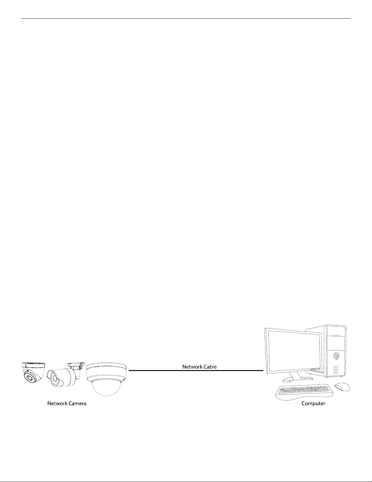
2.1.1. Wiring over the LAN
The following figures show the two ways for a cable connection between a network camera and a
computer.
Purpose
• To test the network camera, you can directly connect the network camera to the computer with a
network cable as shown.
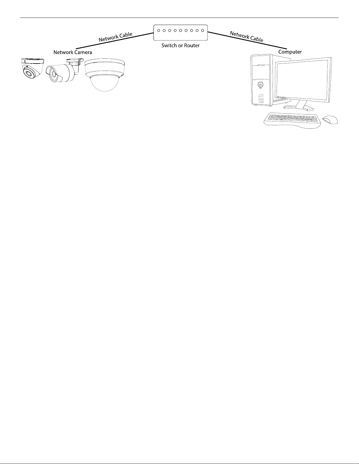
• Refer to figure to set a network camera over the LAN via a switch or a router.
Figure 1, Connecting Directly
UM IP Network Camera 071619NA 14
Page 15
IP Network Camera User Manual
Figure 2, Connecting via a Switch or a Router
2.1.2. Activating the Camera
You are required to activate the camera first by setting a strong password for it before first use.
Activation via Web browser, activation via Hikvision’s SADP (Search Active Device Protocol) software, and
activation via client software are all supported.
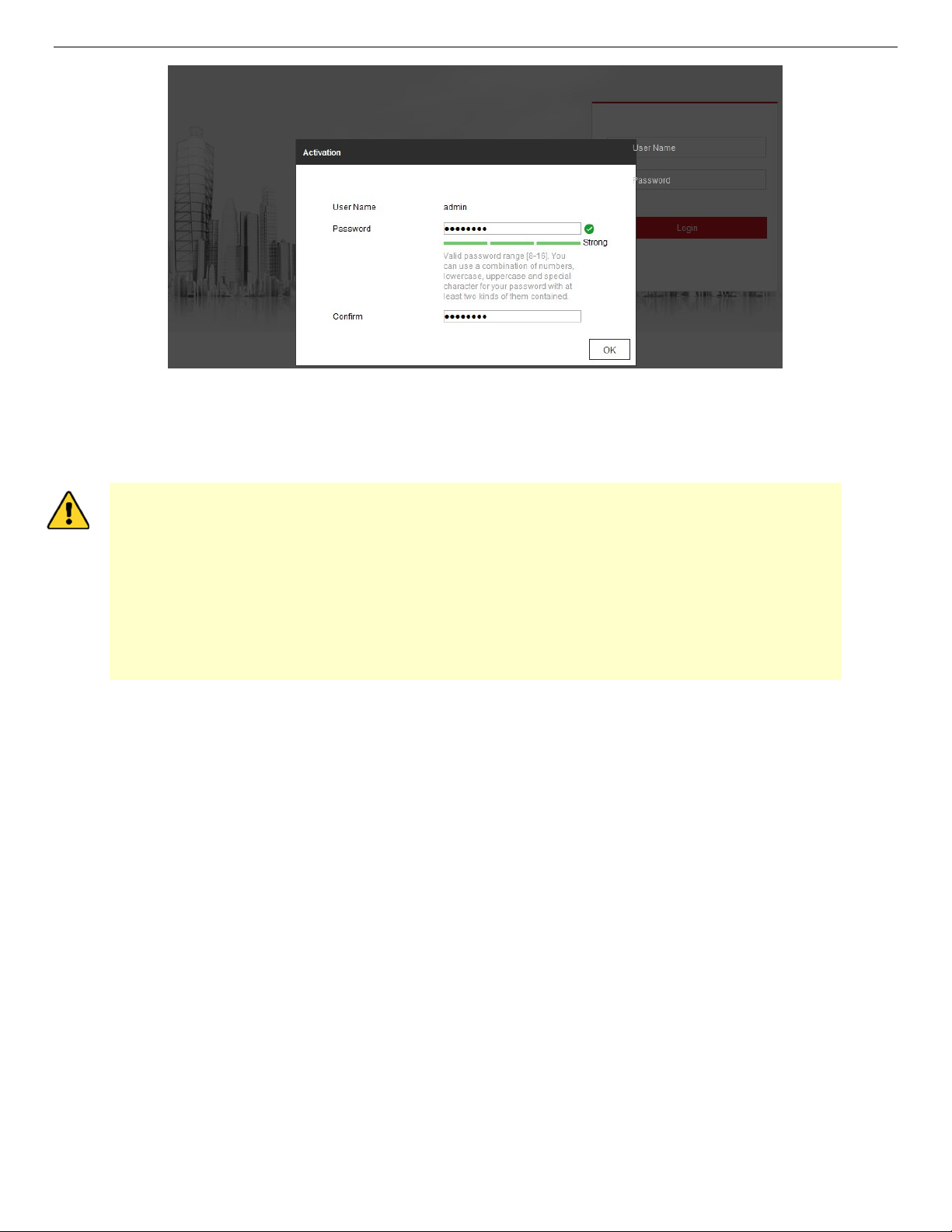
2.1.2.1. Activation via Web Browser
1. Power on the camera and connect the camera to the network.
2. Input the IP address into the Web browser address bar, and click Enter to enter the activation
interface.
NOTES: The default IP address of the camera is 192.168.1.64.
The computer and the camera should belong to the same subnet.
For cameras that enable DHCP by default, you must use the SADP software to search for the IP
address.
UM IP Network Camera 071619NA 15
Page 16
IP Network Camera User Manual
Figure 3, Activation via Web Browser
3. Create and input a password into the password field. A password containing the user name is not
allowed.
STRONG PASSWORD RECOMMENDED – We highly recommend that you create a strong password
of your own choosing (using a minimum of eight characters, including at least three of the
following categories: upper case letters, lower case letters, numbers, and special
characters) in order to increase the security of your product. We also recommend that you
reset your password regularly. Especially in high security systems, resetting the password
monthly or weekly can better protect your product.
Proper configuration of all passwords and other security settings is the responsibility of the
installer and/or end-user.
4. Confirm the password.
5. Click OK to save the password and enter the live view interface.
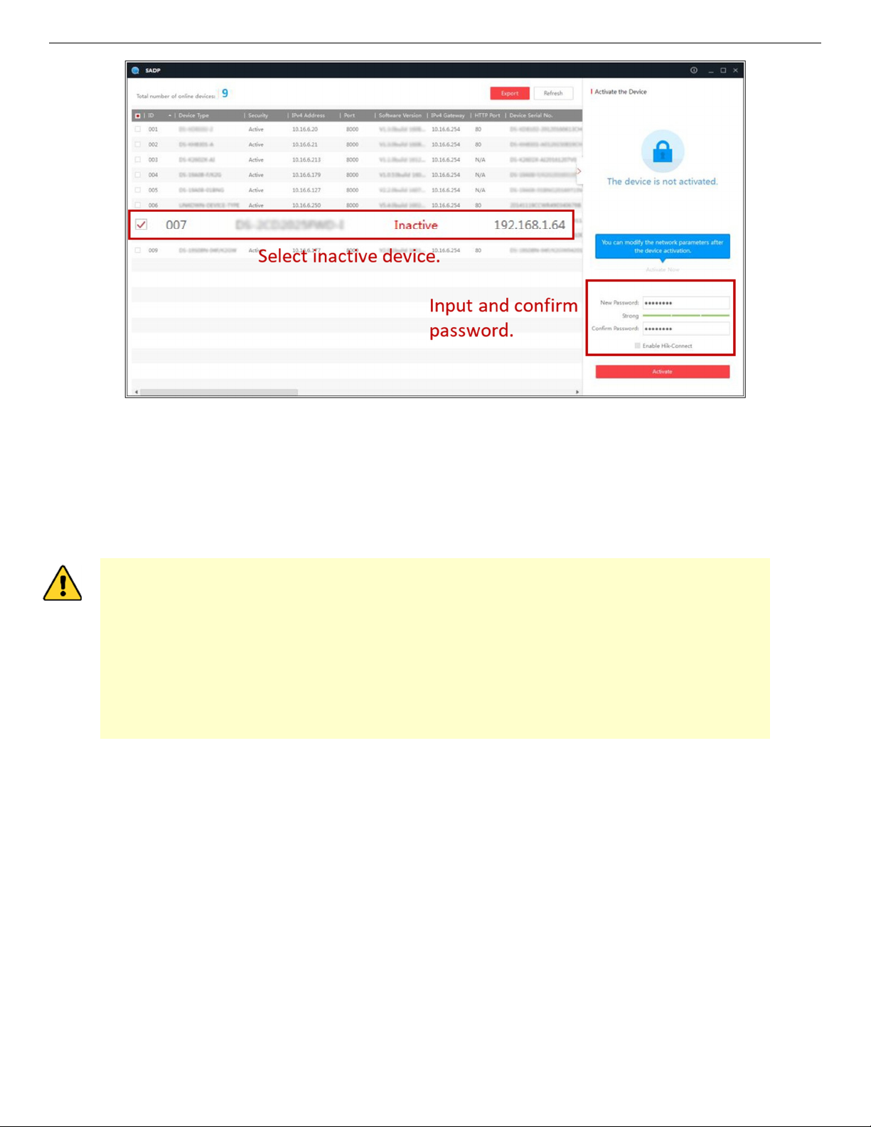
2.1.2.2. Activation via SADP Software
SADP software is used to detect the online device, activate the camera, and reset the password.
Get the SADP software from the supplied disk or the official Website, and install the SADP according to the
prompts. Follow these steps to activate the camera:
1. Run the SADP software to search for online devices.
1. Check the device status from the device list, and select the inactive device.
UM IP Network Camera 071619NA 16
Page 17
IP Network Camera User Manual
Figure 4, SADP Interface
NOTE: The SADP software supports activating the camera in batch. Refer to the SADP software user
manual for details.
2. Create and input the password in the password field, and confirm the password. A password
containing the user name is not allowed.
STRONG PASSWORD RECOMMENDED – We highly recommend that you create a strong password
of your own choosing (using a minimum of eight characters, including at least three of the
following categories: upper case letters, lower case letters, numbers, and special
characters) in order to increase the security of your product. We also recommend that you
reset your password regularly. Especially in high security systems, resetting the password
monthly or weekly can better protect your product.
Proper configuration of all passwords and other security settings is the responsibility of the
installer and/or end-user.
NOTE: You can enable the Hik-Connect service for the device during activation.
3. Click Activate to start activation.
NOTE: You can check whether the activation is completed on the pop-up window. If activation failed,
please make sure that the password meets the requirement and try again.
4. Change the device IP address to the same subnet as your computer by either modifying the IP address
manually or checking the Enable DHCP checkbox.
UM IP Network Camera 071619NA 17
Page 18
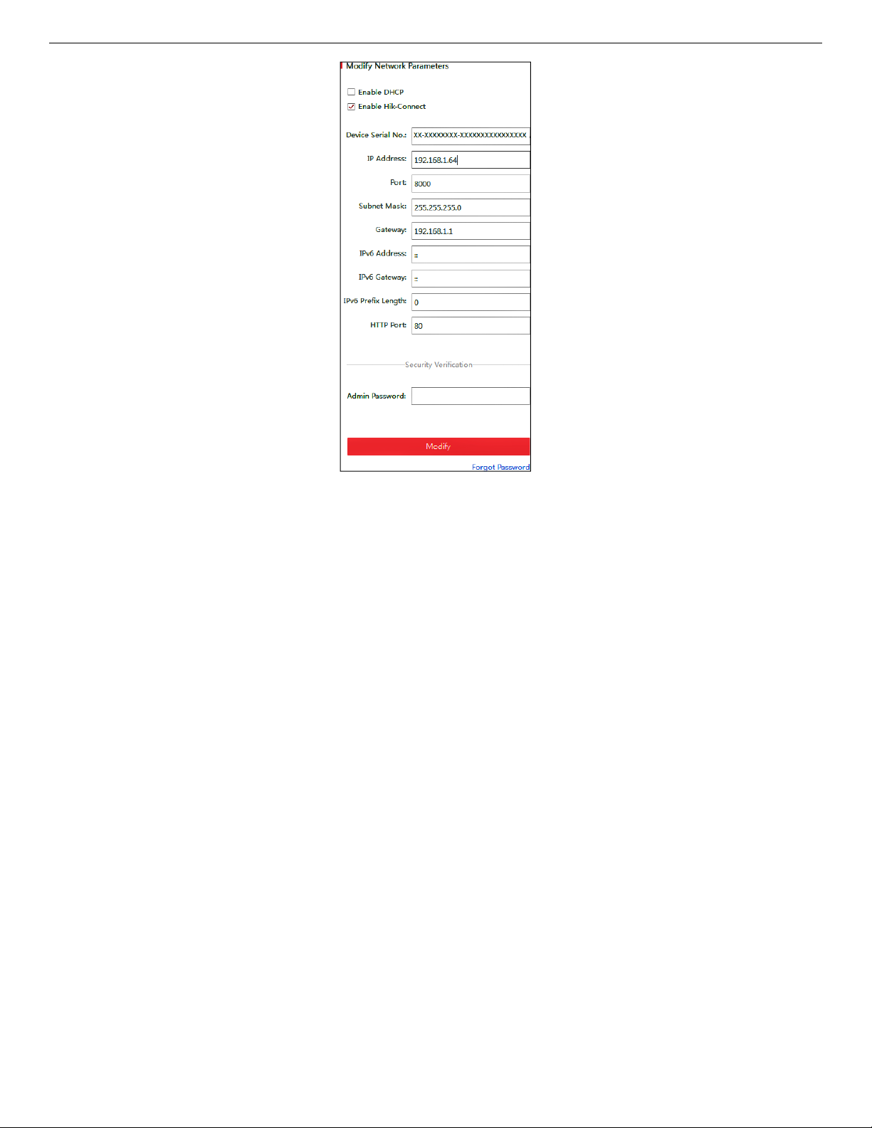
IP Network Camera User Manual
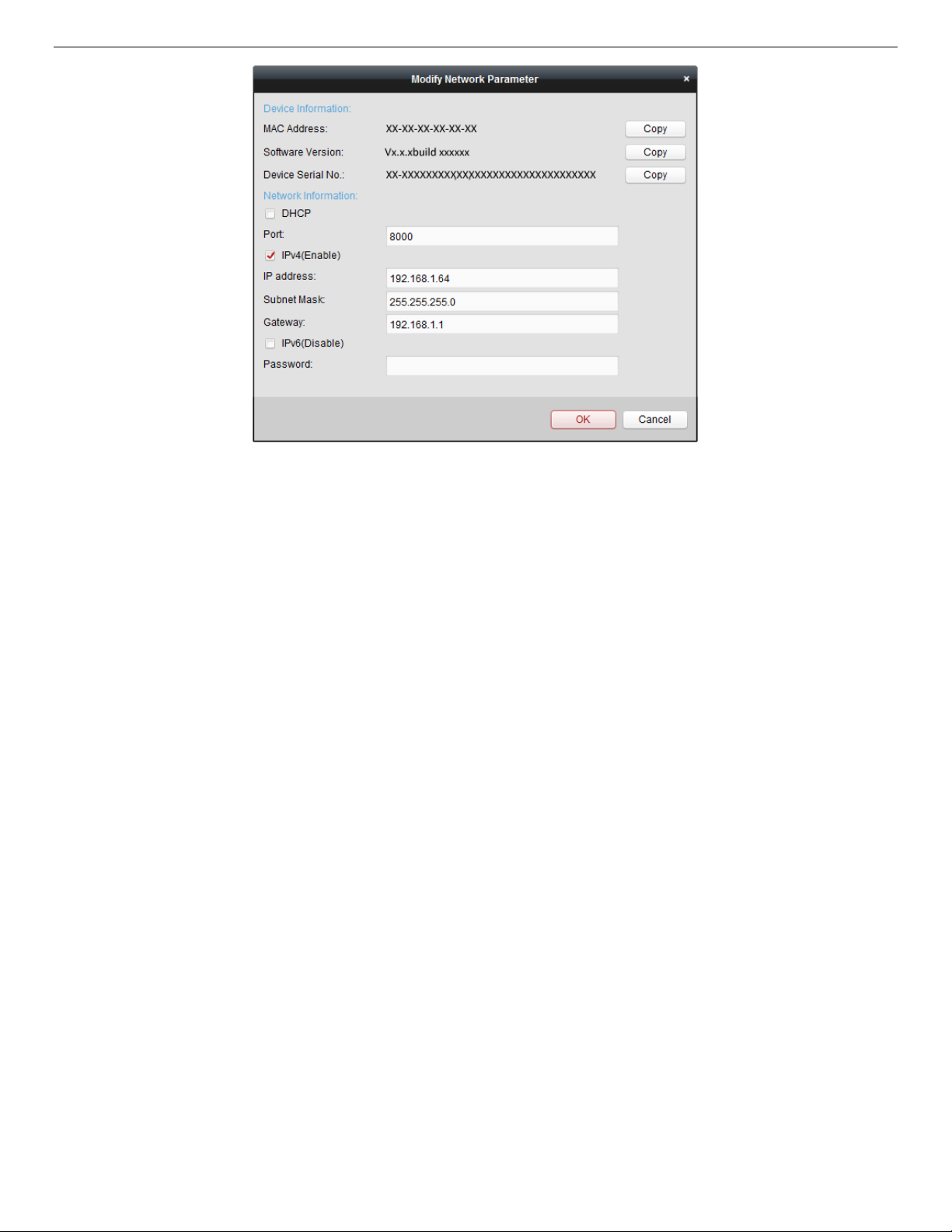
Figure 5, Modify the IP Address
5. Input the admin password and click Modify to activate your IP address modification.
NOTE: Batch IP address modification is supported by SADP. Refer to the SADP user manual for details.
2.1.2.3. Activation via Client Software
The client software is versatile video management software for multiple kinds of devices.
Get the client software from the supplied disk or the official Website, and install the software according
to the prompts. Follow the steps to activate the camera.
1. Run the client software, and the software control panel pops up, as shown below.
UM IP Network Camera 071619NA 18
Page 19
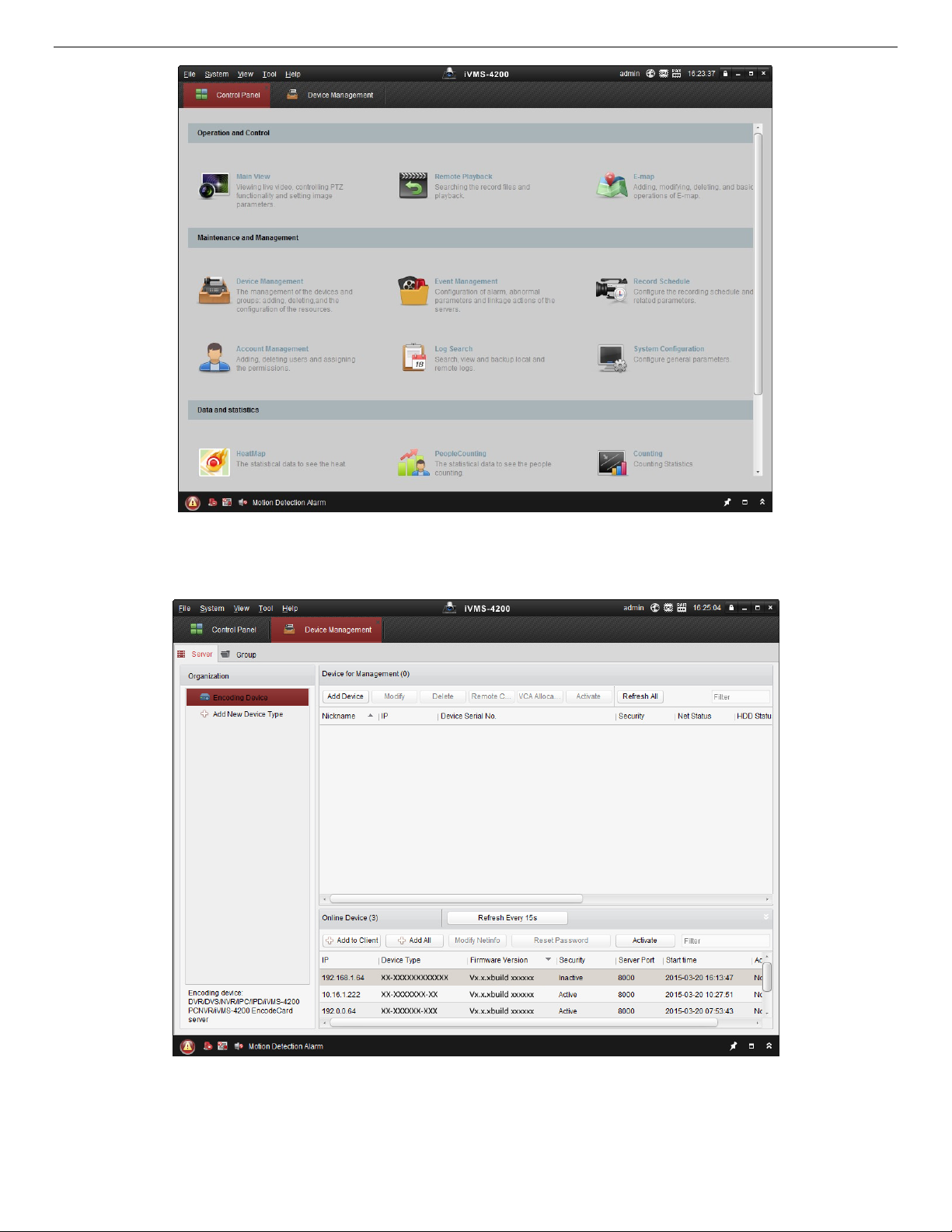
IP Network Camera User Manual
Figure 6, Control Panel
2. Click the Device Management icon to enter the Device Management interface, as shown below.
Figure 7, Device Management Interface
3. Check the device status from the device list, and select an inactive device.
4. Click the Activate button to pop up the Activation interface.
UM IP Network Camera 071619NA 19
Page 20
IP Network Camera User Manual
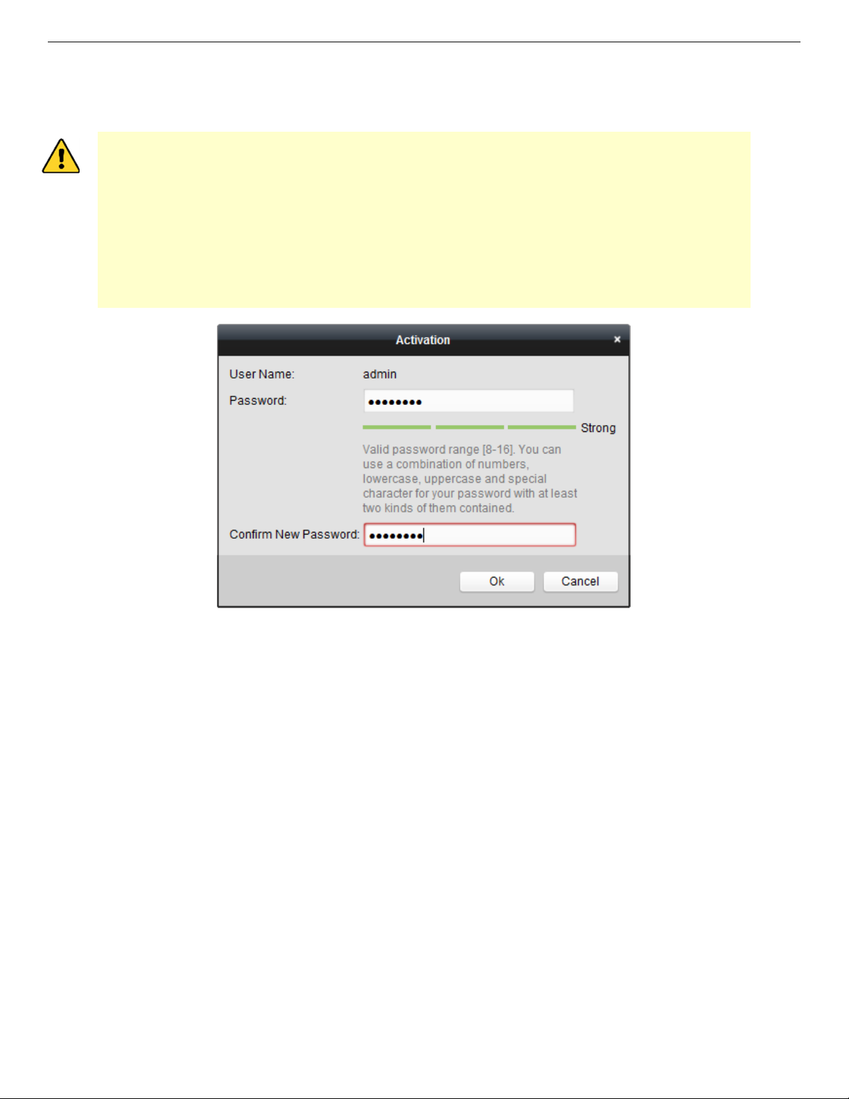
5. Create a password, input the password in the password field, and confirm the password.
NOTE: A password containing the user name is not allowed.
STRONG PASSWORD RECOMMENDED – We highly recommend that you create a strong password
of your own choosing (using a minimum of eight characters, including at least three of the
following categories: upper case letters, lower case letters, numbers, and special
characters) in order to increase the security of your product. We also recommend that you
reset your password regularly. Especially in high security systems, resetting the password
monthly or weekly can better protect your product.
Proper configuration of all passwords and other security settings is the responsibility of the
installer and/or end-user.
Figure 8, Activation Interface (Client Software)
6. Click the OK button to start activation.
7. Click the Modify Netinfo button to pop up the Network Parameter Modification interface, as shown in
the figure below.
UM IP Network Camera 071619NA 20
Page 21
IP Network Camera User Manual
Figure 9, Modifying the Network Parameters
8. Change the device IP address to the same subnet as your computer by either modifying the IP address
manually or checking the Enable DHCP checkbox.
9. Input the password to activate your IP address modification.
2.1.3. (Optional) Setting Security Question
Security question is used to reset the admin password when the admin user forgets the password.
Admin user can follow the pop-up window to complete the security question settings during camera
activation, or the admin user can go to the User Management interface to set up the function.
2.2. Setting the Network Camera over the WAN
Purpose
This section explains how to connect the network camera to the WAN with a static IP or a dynamic IP.
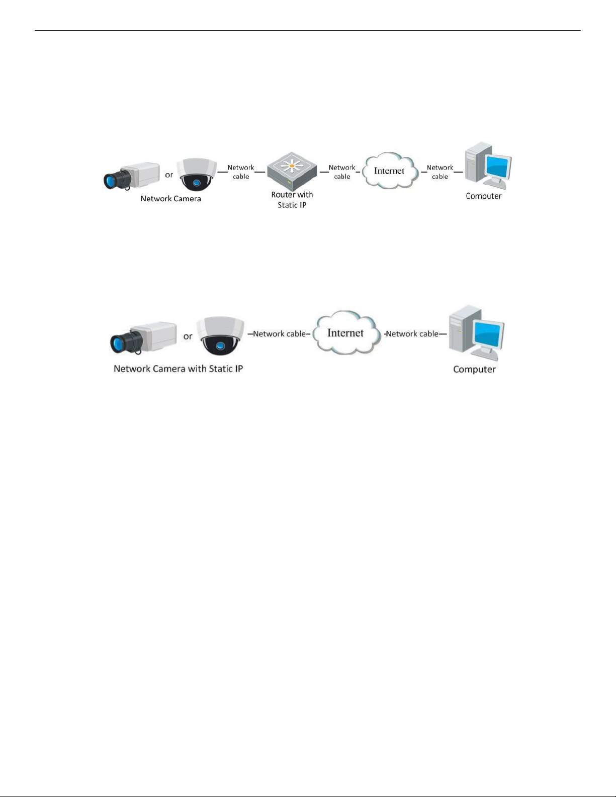
2.2.1. Static IP Connection
Before You Start
Apply a static IP from an ISP (Internet Service Provider). With a static IP address, you can connect the
network camera via a router or connect it to the WAN directly.
• Connecting the Network Camera via a Router
˗ Connect the network camera to the router.
˗ Assign a LAN IP address, the subnet mask, and the gateway.
˗ Save the static IP in the router.
UM IP Network Camera 071619NA 21
Page 22
IP Network Camera User Manual
˗ Set port mapping, e.g., 80, 8000, and 554 ports. The steps for port mapping vary by router. Please
call the router manufacturer for assistance with port mapping.
NOTE: Refer to
˗ Visit the network camera through a Web browser or the client software over the internet.
• Connecting Network Camera with Static IP Address Directly
You can also save the static IP address in the camera and directly connect it to the internet without
using a router. Refer to
Appendix 2
Figure 10, Accessing the Camera through a Router with a Static IP Address
for detailed information about port mapping.
Section 2.1.2
for detailed IP address configuration of the network camera.
Figure 11, Accessing a Camera with a Static IP Address Directly
2.2.2. Dynamic IP Address Connection
Before You Start
Apply a dynamic IP address from an ISP. With a dynamic IP address, you can connect the network camera
to a modem or a router.
2.2.2.1. Connecting Network Camera via a Router
1. Connect the network camera to the router.
2. In the camera, assign a LAN IP address, the subnet mask, and the gateway. Refer to
detailed IP address configuration of the network camera.
3. In the router, set the PPPoE user name, password, and confirm the password.
4. Set port mapping. E.g. 80, 8000, and 554 ports. The steps for port mapping vary by router. Contact your
router manufacturer for assistance with port mapping.
NOTE: Refer to
Appendix 2
for detailed information about port mapping.
Section 2.1.2
for
5. Apply a domain name from a domain name provider.
6. Configure the DDNS settings in the setting interface of the router.
7. Visit the camera via the applied domain name.
UM IP Network Camera 071619NA 22
Page 23
IP Network Camera User Manual
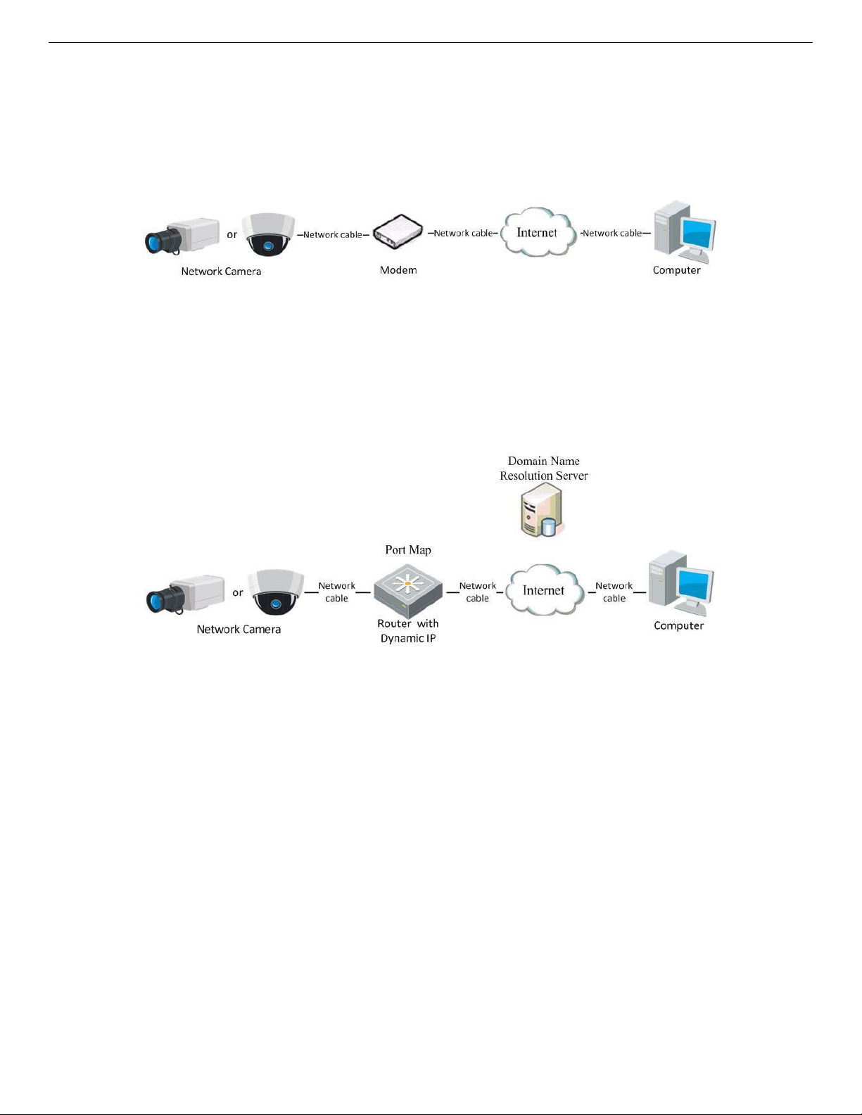
2.2.2.2. Connecting Network Camera via a Modem
Purpose
This camera supports the PPPoE auto dial-up function. The camera gets a public IP address by ADSL dialup after the camera is connected to a modem. You need to configure the PPPoE parameters of the
network camera. Refer to
NOTE: The obtained IP address is dynamically assigned via PPPoE, so the IP address always changes
after rebooting the camera. To solve the inconvenience of a dynamic IP, you need to get a
domain name from the DDNS provider (E.g. DynDns.com). Please follow the steps below for
normal domain name resolution and private domain name resolution to solve the problem.
• Normal Domain Name Resolution
Section 7.1.3
Figure 12, Accessing a Camera with a Dynamic IP Address
Configuring PPPoE Settings for detailed configuration.
Figure 13, Normal Domain Name Resolution
˗ Apply a domain name from a domain name provider.
˗ Configure the DDNS settings in the DDNS Settings interface of the network camera. Refer to
7.1.1, Configuring DDNS Settings
˗ Visit the camera via the applied domain name.
for details.
Section
UM IP Network Camera 071619NA 23
Page 24
IP Network Camera User Manual
Chapter 3. Access to the Network Camera
3.1. Accessing by Web Browsers
NOTE: For certain camera models, HTTPS is enabled by default and the camera creates an unsigned
certificate automatically. When you access to the camera the first time, the Web browser
prompts a notification about the certificate issue.
To cancel the notification, install a signed-certificate to the camera. For detailed operation,
see
Section 7.2.6 HTTPS Settings.
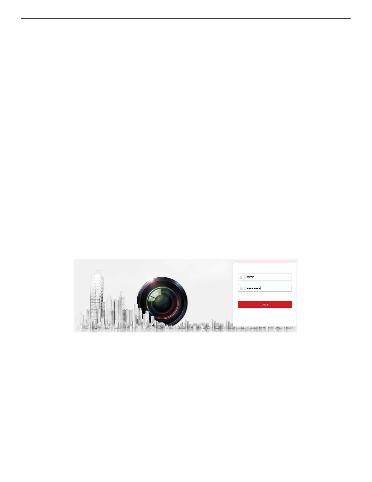
1. Open the Web browser.
2. In the browser address bar, input the network camera’s IP address, and press the Enter key to enter
the login interface.
NOTE: The default IP address is 192.168.1.64. It is recommended that you change the IP address to the
same subnet as your computer.
3. Input the user name and password and click Login.
The admin user should configure the device accounts and user/operator permissions properly. Delete
unnecessary accounts and user/operator permissions.
NOTE: The IP address locks if the admin user performs seven failed password attempts (five attempts
by a user/operator).
Figure 14, Login Interface
4. Click Login.
5. (Optional) Install the plug-in before viewing the live video and operating the camera. Follow the
installation prompts to install the plug-in.
NOTE: For cameras that support plug-in free live view, if you are using Google Chrome 45 and above or
Mozilla Firefox 52 and above, plug-in installation is not required. But Picture and Playback
functions are hidden. To use these functions via a Web browser, change to their lower version,
or change to Internet Explorer 8.0 and above version.
UM IP Network Camera 071619NA 24
Page 25
IP Network Camera User Manual
3.2. Accessing by Client Software
With iVMS-4200 client software (available on the Hikvision Website), you can view the live video and
manage the camera with the software.
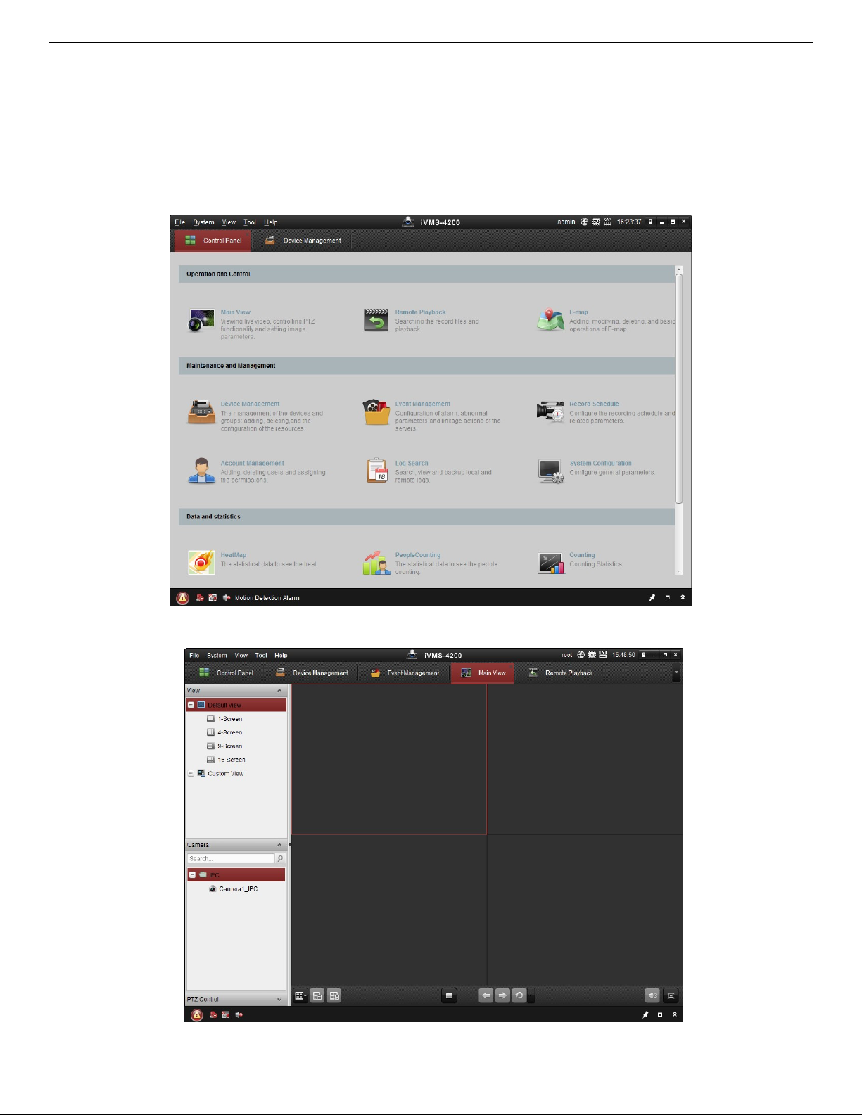
Follow the installation prompts to install the software. The iVMS-4200 client software live view interface
and control panel are shown below.
Figure 15, iVMS-4200 Control Panel
Figure 16, iVMS-4200 Main View
UM IP Network Camera 071619NA 25
Page 26
IP Network Camera User Manual
Chapter 4. Wi-Fi Settings
By connecting to the wireless network, you don’t need to use cables for the network connection, which is
very convenient for the actual surveillance application.
NOTE: This chapter is applicable only for cameras with a built-in Wi-Fi module.
4.1. Configuring Wi-Fi Connection in Manage and Ad-Hoc Modes
Purpose
Two connection modes are supported. Choose a mode as desired and perform the steps to configure the
Wi-Fi.
4.1.1. Wireless Connection in Manage Mode
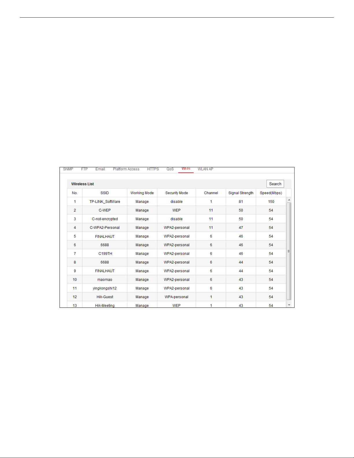
1. Enter the Wi-Fi configuration interface, Configuration> Network> Advanced Settings> Wi-Fi.
Figure 17, Wi-Fi List
2. Click Search to search the online wireless connections.
3. Click to choose a wireless connection on the list.
UM IP Network Camera 071619NA 26
Page 27
IP Network Camera User Manual
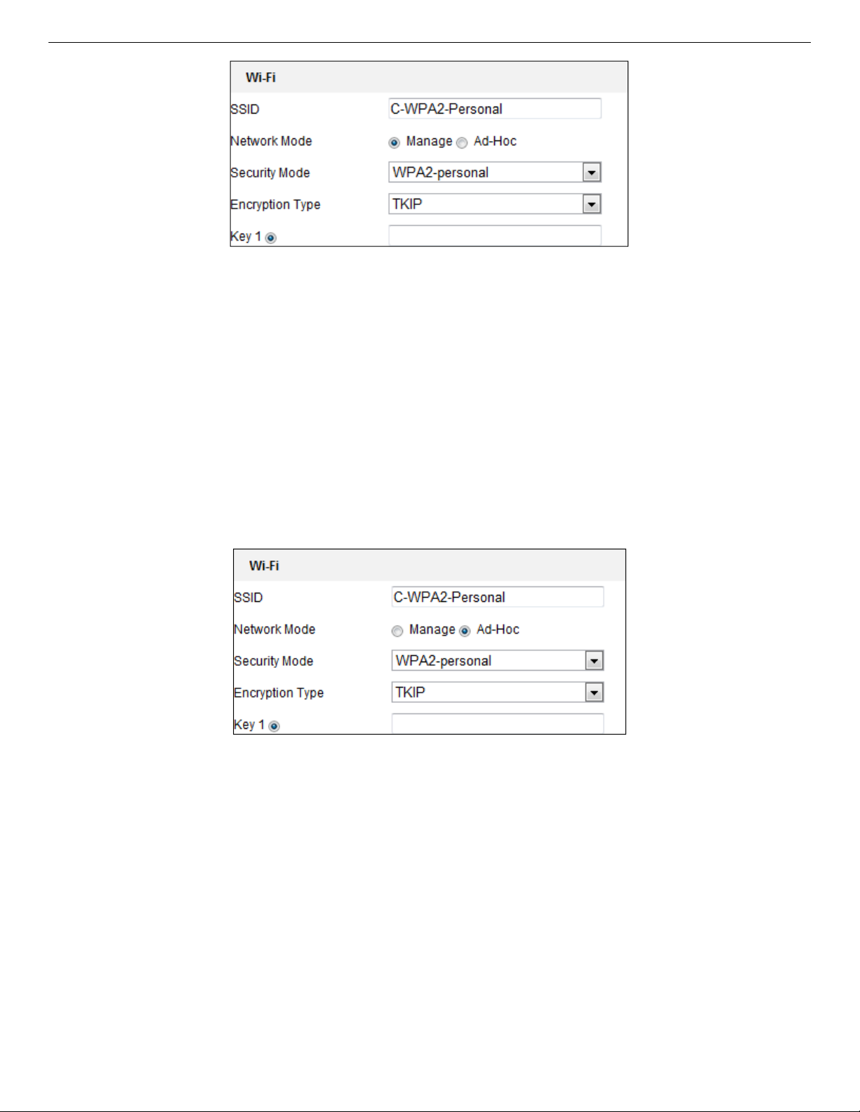
Figure 18, Wi-Fi Setting − Manage Mode
4. Check the radio button to set the Network Mode to Manage, and the network Security Mode is
automatically shown when you select the wireless network (don’t change it manually).
NOTE: These parameters are identical to those of the router.
5. Enter the key to connect the wireless network. The key should be that of the wireless network
connection you set on the router.
4.1.2. Wireless Connection in Ad-Hoc Mode
If you choose Ad-Hoc Mode, you don’t need to connect the wireless camera via a router. The scenario is
the same as connecting the camera and PC directly with a network cable.
Figure 19, Wi-Fi Setting − Ad-Hoc
1. Choose Ad-Hoc Network Mode.
2. Customize an SSID (Service Set IDentifier) to identify the camera access point (maximum 32
characters).
3. Choose the wireless connection Security Mode.
4. Enable Wi-Fi wireless network function on your PC.
5. On the PC, search the networks for the camera SSID.
UM IP Network Camera 071619NA 27
Page 28
IP Network Camera User Manual
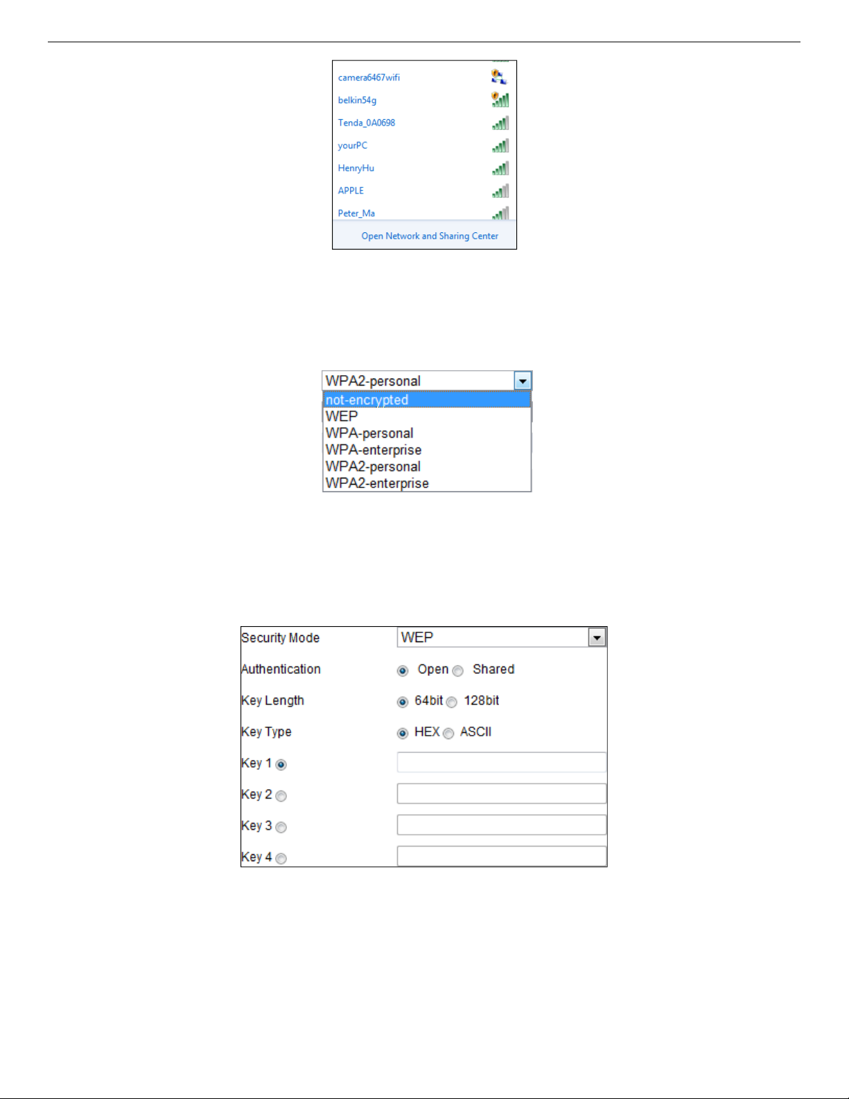
Figure 20, Ad-Hoc Connection Point
6. Choose the camera’s SSID and connect.
4.1.3. Security Mode Description:
Figure 21, Security Mode
You can choose the Security Mode as not-encrypted, WEP, WPA-personal, WPA-enterprise, WPA2personal, and WPA2-enterprise.
• WEP Mode
Figure 22, WEP Mode
˗ Authentication − Select Open or Shared Key System Authentication, depending on the method used
by your access point. Not all access points have this option, in which case they probably use Open
System, which is sometimes known as SSID Authentication.
˗ Key Length - This sets the length of the key used for the wireless encryption, 64 or 128 bits. The
encryption key length can sometimes be shown as 40/64 and 104/128.
UM IP Network Camera 071619NA 28
Page 29
IP Network Camera User Manual
˗ Key Type - The key types available depend on the access point being used. The following options
are available:
> HEX: Allows you to manually enter the hex key.
> ASCII: In this method the string must be exactly five characters for 64-bit WEP and 13
characters for 128-bit WEP.
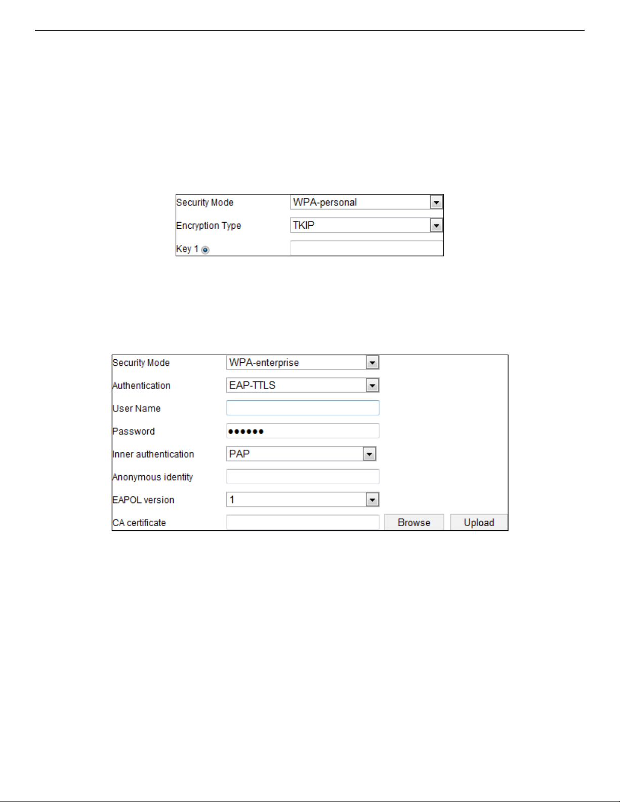
> WPA-personal and WPA2-personal Mode: Enter the required Pre-Shared Key for the access
point, which can be a hexadecimal number or a passphrase.
Figure 23, Security Mode − WPA-Personal
> WPA- enterprise and WPA2-enterprise Mode: Choose the type of client/server authentication
being used by the access point, EAP-TLS or EAP-PEAP.
• EAP-TLS
˗
Identity
˗
Private Key Password
˗
EAPOL Version
Figure 24, EAP-TLS
− Enter the user ID to present to the network.
− Enter the password for your user ID.
− Select the version used (1 or 2) in your access point.
˗
CA Certificates
− Upload a CA certificate to present to the access point for authentication.
• EAP-PEAP
˗
User Name
˗
Password
˗
PEAP Version
UM IP Network Camera 071619NA 29
− Enter the user name to present to the network.
− Enter the network password.
− Select the PEAP version used at the access point.
Page 30
IP Network Camera User Manual
˗
Label
− Select the label used by the access point.
˗
EAPOL Version
˗
CA Certificates
− Select version (1 or 2) depending on the version used at the access point.
− Upload a CA certificate to present to the access point for authentication.
STRONG PASSWORD RECOMMENDED – We highly recommend that you create a strong password
of your own choosing (using a minimum of eight characters, including at least three of the
following categories: upper case letters, lower case letters, numbers, and special
characters) in order to increase the security of your product. We also recommend that you
reset your password regularly. Especially in high security systems, resetting the password
monthly or weekly can better protect your product.
Proper configuration of all passwords and other security settings is the responsibility of the
installer and/or end-user.
4.2. Easy Wi-Fi Connection with WPS Function
Purpose
Setting a wireless network connection is never easy. To avoid the complexity of setting up the wireless
connection, you can enable the WPS function.
WPS (Wi-Fi Protected Setup) refers to an easy procedure to configure an encrypted connection between a
device and a wireless router. WPS makes it easy to add new devices to an existing network without
entering long passphrases. There are two modes of WPS connection, PBC mode and PIN mode.
NOTE: If you enable the WPS function, you do not need to configure parameters such as encryption
type, and you don’t need to know the wireless connection key.
Figure 25, Wi-Fi Settings - WPS
PBC Mode
PBC stands for Push-Button-Configuration, in which the user simply has to push a button, either an actual
or virtual one (as the button on the Internet Explorer browser configuration interface), on both
the Access Point (and a registrar of the network) and the new wireless client device.
1. Check the checkbox to enable WPS.
UM IP Network Camera 071619NA 30
Page 31
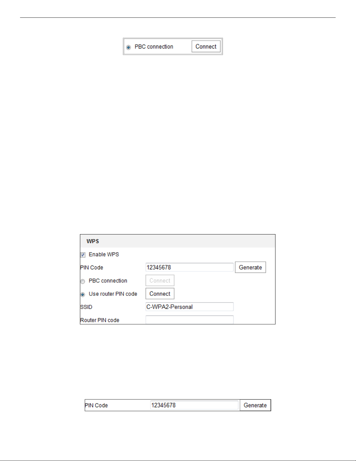
IP Network Camera User Manual
2. Set the connection mode to PBC.
NOTE: Both the Access Point and connecting device must support this mode.
3. Check the Wi-Fi router to see if there is a WPS button. If yes, press the button and you will see the
indicator near the button start flashing, which means the WPS function of the router is enabled. For
detailed operation, please see the router’s user guide.
4. Press the WPS button to enable the function on the camera.
NOTE: If there is no WPS button on the camera, you can also click the virtual button on the Web
interface to enable the PBC function.
5. Click the Connect button. If PBC Mode is enabled both in the router and on the camera, the camera and
the wireless network will connect automatically.
PIN Mode
PIN mode requires a Personal Identification Number (PIN) to be read from either a sticker or the display on
the new wireless device. This PIN must then be entered to connect to the network Access Point.
1. Choose a wireless connection on the list and the SSID is loaded automatically.
2. Choose Use route PIN code.
Figure 26, Use PIN Code
NOTE: If the PIN code is generated from the router, enter the PIN code you get from the router in the
Router PIN code field.
3. Click Connect, or generate the PIN code on the camera. The PIN code expiration time is 120 seconds.
4. Click Generate.
5. Enter the code to the router.
UM IP Network Camera 071619NA 31
Page 32

IP Network Camera User Manual
4.3. IP Property Settings for Wireless Network Connection
The default IP address of the wireless network interface controller is 192.168.1.64. Once you connect to
the wireless network, you can change the IP address.
1. Enter the TCP/IP configuration interface, Configuration > Network > Basic Settings > TCP/IP.
2. Select the Wlan tab.
Figure 27, Setting WLAN Parameters
3. Customize the IPv4 Address, the IPv4 Subnet Mask, and the Default Gateway. The setting procedure is
the same as that for a LAN.
NOTE: If you want to be assigned the IP address automatically, check the DHCP checkbox.
UM IP Network Camera 071619NA 32
Page 33

IP Network Camera User Manual
Chapter 5. Live View
Purpose
The live view page lets you view real-time video, capture images, control PTZ cameras, set/call presets,
and configure video parameters.
Log in the network camera to enter the live view page, or click Live View on the menu bar of the main
page.
Live View Page
5.1. Live View Page Descriptions
Figure 28, Live View Page
• Menu Bar: Click the relevant tab to enter Live View, Playback, Picture, Application, and Configuration
page respectively.
• Live View Window: Display live video.
• Toolbar: Toolbar allows you to adjust the live view window size, the stream type, and the plug-ins. It
also allows you to process the operations on the live view page (e.g., start/stop live view, capture,
record, audio on/off, two-way audio, start/stop digital zoom, etc.).
For IE (Internet Explorer) users, plug-ins such as Web Components and Quicktime are selectable. For nonIE users, Web Components, Quicktime, VLC, or MJPEG are selectable if they are supported by the Web
browser.
NOTE:
For cameras that support plug-in free live view, if Google Chrome 45 and above version or
Mozilla Firefox 52 and above version is used, plug-in installation is not required. But Picture and
Playback functions are hidden. To use these functions via a Web browser, change to their lower
versions, or use Internet Explorer 8.0 and above version.
UM IP Network Camera 071619NA 33
Page 34

IP Network Camera User Manual
Icon
Description
• PTZ Control: Perform camera panning, tilting, and zooming actions. Control the light and the wiper (only
available for cameras supporting PTZ function).
• Preset/Patrol Settings: Set/call/delete PTZ camera presets or patrols.
5.2. Starting Live View
In the live view window, click on the toolbar to start the camera’s live view.
Figure 29, Live View Toolbar
Table 5-1 Toolbar Descriptions
/ Start/stop live view
The window size is 4:3
The window size is 16:9
The original widow size
Self-adaptive window size
, , , etc.
/ Manually start/stop recording
/ Audio on and adjust volume/Mute
/ Turn on/off microphone
/
NOTE: The icons vary by camera.
Live view with the different video streams (supported video streams vary by camera model)
Click to select third-party plug-in
Manually capture the picture
Start/stop digital zoom function
5.3. Recording and Capturing Pictures Manually
In the live view interface, click on the toolbar to capture live pictures or click to record the live view.
The saving paths of the captured pictures and clips can be set on the Configuration > Local page.
NOTE: The captured image will be saved as a JPEG file or BMP file on your computer.
5.4. Operating PTZ Control
Purpose
In the live view interface, you can use the PTZ control buttons for pan/tilt/zoom control of the camera.
NOTE: For PTZ control, the camera connected to the network must support the PTZ function or have a
pan/tilt unit installed. Properly set the PTZ parameters on the RS-485 settings page (refer to
Section 6.2.4, Configuring RS-485 Settings).
5.4.1. PTZ Control Panel
UM IP Network Camera 071619NA 34
Page 35

IP Network Camera User Manual
Icon
Description
Zoom in/out
Focus near/far
Iris +/-
PTZ speed adjustment
Light on/off
Wiper on/off
Auxiliary focus
Initialize lens
Adjust speed of pan/tilt movements
Start Manual Tracking
Start 3D Zoom
1. On the live view page, click next to the right side of the live view window to show the PTZ control
panel (click to hide it).
2. Click the direction buttons to control the pan/tilt movements.
Figure 30, PTZ Control Panel
3. Click the zoom/focus/iris buttons for lens control.
NOTES: There are eight direction arrows ( , , , , , , , ) in the control panel. Click the
arrows to adjust the relative positions.
For cameras that support lens movements only, the direction buttons are invalid.
Table 5-2 Descriptions of PTZ Control Panel
5.4.2. Setting/Calling a Preset
• Setting a Preset
1. In the PTZ control panel, select a preset number from the preset list.
UM IP Network Camera 071619NA 35
Page 36

IP Network Camera User Manual
Figure 31, Setting a Preset
2. Use the PTZ control buttons to move the lens to the desired position.
• Pan the camera to the right or left
• Tilt the camera up or down
• Zoom in or out
• Refocus the lens
3. Click to finish setting the current preset.
4. You can click to delete the preset.
• Calling a Preset
This feature enables the camera to point to a predetermined preset scene manually or when an event
takes place.
You can call a defined preset at any time.
In the PTZ control panel, select a defined preset from the list and click to call it, or you can place the
mouse on the presets interface and call the preset by typing the preset no.
Figure 32, Calling a Preset
5.4.3. Setting/Calling a Patrol
NOTE: No less than two presets have to be configured before you can set a patrol.
1. Click to enter the patrol configuration interface.
UM IP Network Camera 071619NA 36
Page 37

IP Network Camera User Manual
2. Select a path no., and click to add the configured preset.
3. Select the preset, and input the patrol duration and patrol speed.
4. Click OK to save the first preset.
5. Follow the steps above to add other presets.
6. Click OK to save the patrol.
Figure 33, Add Patrol Path
7. Click to start the patrol, and click to stop it.
8. (Optional) Click to delete the patrol.
UM IP Network Camera 071619NA 37
Page 38

IP Network Camera User Manual
Chapter 6. Network Camera Configuration
6.1. Configuring Local Parameters
Purpose
Local configuration refers to live view, record file, and captured picture parameters. The record files and
captured pictures are the ones you record and capture using a Web browser and thus their saving paths
are on the PC running the browser.
1. Enter the Local Configuration interface: Configuration > Local.
2. Configure the following settings:
• Live View Parameters: Set the protocol type and live view performance.
- Protocol Type: TCP, UDP, MULTICAST, and HTTP are selectable
TCP: Ensures complete delivery of streaming data and better video quality, yet the real-time
transmission will be affected
UDP: Provides real-time audio and video streams
HTTP: Allows the same quality as TCP without setting specific ports for streaming under some
network environments
MULTICAST: It’s recommended to select MCAST type when using the Multicast function. For
detailed information about Multicast, refer to
- Play Performance: Set the live view performance to Shortest Delay, Balanced, Fluent, or Custom.
For Custom, you can set the live view frame rate.
- Rules: It refers to the rules on your local browser. Select enable or disable to display or not
display colored marks when motion detection, face detection, or intrusion detection is
triggered (e.g., enabled as the rules are, and the face detection is enabled as well, when a face
is detected, it will be marked with a green rectangle on live view).
- Display POS Information: If enabled, the detected target’s feature information is dynamically
displayed near the target in the live image. The feature information for different functions vary.
For example, ID and waiting time for Queue Management, height for People Counting, etc.
NOTE: Display POS Information is available only for certain camera models.
- Image Format: Choose the image format for picture capture.
Section 7.1, Configuring TCP/IP Settings.
UM IP Network Camera 071619NA 38
Page 39

IP Network Camera User Manual
Figure 34, Live View Parameters
• Record File Settings: Set the saving path of the recorded video files. Valid for the record files you
recorded with the Web browser.
- Record File Size: Select the packed size of the manually recorded and downloaded video files
to 256 MB, 512 MB, or 1 GB. After selection, the maximum record file size is the selected value.
• Save record files to: Set the saving path for the manually recorded video files.
- Save downloaded files to: Set the saving path for the downloaded video files in playback mode.
• Picture and Clip Settings: Set the saving paths of the captured pictures and clipped video files.
Valid for the pictures you capture with the Web browser.
- Save snapshots in live view to: Set the saving path of the manually captured pictures in live
view mode.
- Save snapshots when playback to: Set the saving path of the captured pictures in playback
mode.
- Save clips to: Set the saving path of the clipped video files in playback mode.
NOTE: You can click Browse to change the directory for saving the clips and pictures, and click Open to
open the set folder of clips and picture saving.
3. Click Save to save the settings.
6.2. Configure System Settings
Purpose
Follow the instructions below to configure the system settings, include System Settings, Maintenance,
Security, User Management, etc.
6.2.1. Configuring Basic Information
Enter the Device Information interface: Configuration > System > System Settings > Basic Information.
In the Basic Information interface, you can edit the Device Name and Device No. Other information of the
network camera, such as Model, Serial No., Firmware Version, Encoding Version, Number of Channels,
Number of HDDs, Number of Alarm Input, and Number of Alarm Output are displayed. The information
cannot be changed in this menu. It is the reference for future maintenance or modification.
UM IP Network Camera 071619NA 39
Page 40

IP Network Camera User Manual
6.2.2. Configuring Time Settings
Purpose
You can follow the instructions in this section to configure the time synchronization and DST settings.
1. Enter the Time Settings interface, Configuration > System> System Settings > Time Settings.
Figure 35, Time Settings
2. Select the Time Zone of your location from the drop-down menu.
3. Configure the NTP settings.
1) Click to enable the NTP function.
2) Configure the following settings:
•
Server Address: IP address of NTP server
•
NTP Port: Port of NTP server
•
Interval: The time interval between the two synchronizing actions with NTP server
3) (Optional) Click the Test button to test the time synchronization function via NTP server.
UM IP Network Camera 071619NA 40
Page 41

IP Network Camera User Manual
Figure 36, Time Sync by NTP Server
NOTE: If the camera is connected to a public network, use an NTP server that has a time
synchronization function such as the server at the National Time Center (IP Address:
210.72.145.44). If the camera is in a customized network, NTP software can be used to establish
an NTP server for time synchronization.
4. Configure the manual time synchronization.
1) Check Manual Time Sync. to enable the manual time synchronization function.
2) Click the icon to select the date and time on the pop-up calendar.
3) (Optional) Check Sync. with computer time to synchronize the device time with the local PC.
Figure 37, Time Sync Manually
5. Click Save to save the settings.
6.2.3. Configuring RS-232 Settings
The RS-232 port can be used in two ways:
• Parameters Configuration: Connect a computer to the camera through the serial port. Device
parameters can be configured by using software such as HyperTerminal. The serial port parameters
must be the same as the serial port parameters of the camera.
• Transparent Channel: Connect a serial device directly to the camera. The serial device will be
controlled remotely by the computer through the network.
UM IP Network Camera 071619NA 41
Page 42

IP Network Camera User Manual
1. Enter RS-232 Port Setting interface: Configuration > System > System Settings > RS232.
2. Configure the Baud Rate, Data Bit, Stop Bit, Parity, Flow Control, and Usage.
Figure 38, RS-232 Settings
NOTE: To connect the camera by the RS-232 port, the RS-232 parameters should be exactly the same
as the parameters you configured here.
3. Click Save to save the settings.
6.2.4. Configuring RS-485 Settings
Purpose
The RS-485 serial port is used to control the PTZ of the camera. Configure the PTZ parameters before you
control the PTZ unit.
1. Enter RS-485 Port Setting interface: Configuration > System > System Settings > RS485.
Figure 39, RS-485 Settings
UM IP Network Camera 071619NA 42
Page 43

IP Network Camera User Manual
2. Set the RS-485 parameters and click Save to save the settings.
3. By default, the Baud Rate is set to 9600 bps, the Data Bit is 8, the Stop Bit is 1, and the Parity and Flow
Control is None.
NOTE: The baud rate, PTZ protocol, and PTZ address parameters should be exactly the same as the PTZ
camera parameters.
6.2.5. Configuring DST Settings
Purpose
Daylight Saving Time (DST) is a way of making better use of the natural daylight by setting your clock
forward one hour during the summer months, and back again in the fall.
Configure DST according to your actual demand.
1. Enter the DST configuration interface, Configuration > System > System Settings > DST.
Figure 40, DST Settings
2. Select the start time and the end time.
3. Select DST Bias.
4. Click Save to activate the settings.
6.2.6. Configuring External Devices
Purpose
For devices that support external devices, including a housing wiper or LED light, you can control them via
the Web browser. External devices vary by camera model.
1. Enter the External Device configuration interface, Configuration > System > System Settings > External
Device.
UM IP Network Camera 071619NA 43
Page 44
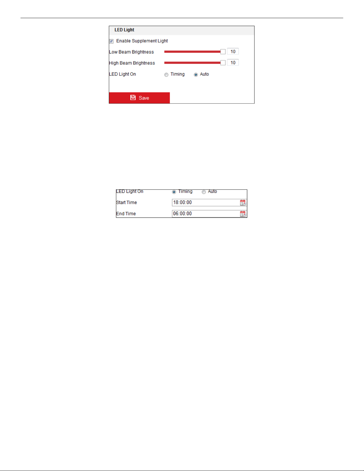
IP Network Camera User Manual
Figure 41, External Device Settings
2. Check the Enable Supplement Light checkbox to enable the LED light.
3. Move the slider to adjust the low beam brightness and high bean brightness.
4. Select the LED light mode. Timing and Auto are selectable.
• Timing: The LED will turn on by the schedule set. Set the Start Time and End Time.
Figure 42, Set Schedule
• Auto: The LED will turn on according to the environment illumination.
5. Click Save to save the settings.
6.2.7. Configuring VCA Resource
Purpose
VCA Resource offers you options to enable certain VCA functions according to actual need when several
VCA functions are available. It helps allocate more resources to the desired functions.
NOTE: DS-2CD2xx6G1 Series Cameras Only: Some Smart VCA functions (line crossing detection,
intrusion detection, region entrance/exit detection) are not functional when using third video
stream, H.265+ video compression, or motion detection.
1. Enter the VCA Resource interface, Configuration > System > System Settings > VCA Resource.
2. Select a desired VCA combination. Available VCA combinations vary by camera model.
3. Click Save to save the settings. A reboot is required after setting the VCA Resource.
NOTES: VCA combinations are mutually exclusive. When you activate one, the others are hidden.
The function may not be supported by some camera models.
6.2.8. Open Source Software License
UM IP Network Camera 071619NA 44
Page 45

IP Network Camera User Manual
Information about the open source software that applies to the IP camera can be checked if required. Go
to Configuration > System Settings > About.
6.3. Maintenance
6.3.1. Upgrade & Maintenance
Purpose
The Upgrade & Maintenance interface allows you to process operations, including reboot, partly restore,
restore to default, export/import the configuration files, and upgrade the device.
1. Enter the Maintenance interface: Configuration > System > Maintenance > Upgrade & Maintenance.
• Reboot: Restart the device.
• Restore: Reset all parameters, except IP parameters and user information, to the default settings.
• Default: Restore all the parameters to the factory default.
NOTE: After restoring the default settings, the IP address is also restored to the default IP address,
please be careful with this action.
For cameras that support Wi-Fi, wireless dial, or the wlan function, the Restore action does not
restore the related settings of mentioned functions to default.
• Information Export
• Device Parameters: Click to export the camera’s current configuration file. This operation requires
admin password to proceed.
For the exported file, you also have to create an encryption password. The encryption password is
required when you import the file to other cameras.
• Diagnose Information: Click to download log and system information.
• Import Config. File: Configuration file is used for batch configuration of the cameras.
1) Click Browse to select the saved configuration file.
2) Click Import and input the encryption password that you set during export.
NOTE: You need to reboot the camera after importing the configuration file.
• Upgrade: Upgrade the device to a particular version.
1) Select the firmware or the firmware directory to locate the upgrade file.
Firmware: Locate the exact path of the upgrade file.
Firmware Directory: Only the directory the upgrade file belongs to is required.
2) Click Browse to select the local upgrade file, and then click Upgrade to start remote upgrade.
UM IP Network Camera 071619NA 45
Page 46

IP Network Camera User Manual
NOTE: The upgrading process will take 1 to 10 minutes. Don't disconnect camera power during the
process. The camera will reboot automatically after the upgrade.
6.3.2. Log
Purpose
The camera’s operation, alarm, exception, and information can be stored in log files. You can also export
the log files on demand.
Before You Start
Configure network storage for the camera or insert an SD card in the camera.
1. Enter the log searching interface: Configuration > System > Maintenance > Log.
Figure 43, Log Searching Interface
2. Specify the log search conditions, including the Major Type, Minor Type, Start Time and End Time.
3. Click Search to search log files. The matched log files will be displayed on the log list interface.
Figure 44, Log Searching
4. To export the log files, click Export to save the log files.
6.3.3. System Service
UM IP Network Camera 071619NA 46
Page 47

IP Network Camera User Manual
Purpose
System service settings refer to the hardware service the camera supports. Supported functions vary by
camera. For cameras that support IR Light, ABF (Auto Back Focus), Auto Defog, or Status LED, you can
select to enable or disable the corresponding service according to your actual demand.
• ABF: When the ABF function is enabled, you can click on the PTZ control panel for auxiliary focus.
• Third Stream: For some models, third stream is not enabled by default. Check Enable Third Stream
checkbox to enable the function.
6.4. Security Settings
Configure the parameters, including Authentication, IP Address Filter, and Security Service on the security
interface.
6.4.1. Authentication
Purpose
You can specifically secure the live view stream data.
1. Enter the Authentication interface, Configuration > System > Security > Authentication.
Figure 45, Authentication
2. Set up authentication method for RTSP authentication and WEB authentication.
CAUTION: Digest is the recommended authentication method for better data security. You must be aware
of the risk if you adopt Basic as the authentication method.
3. Click Save to save the settings.
6.4.2. IP Address Filter
Purpose
This function makes access control possible.
1. Enter the IP Address Filter interface: Configuration > System > Security > IP Address Filter.
UM IP Network Camera 071619NA 47
Page 48

IP Network Camera User Manual
Figure 46, IP Address Filter Interface
2. Check the Enable IP Address Filter checkbox.
3. Select the type of IP Address Filter in the drop-down list, Forbidden and Allowed are selectable.
4. Set the IP Address Filter list.
• Add an IP Address
1) Click Add to add an IP address.
2) Input the IP Address.
Figure 47, Add an IP
3) Click OK to finish adding.
• Modify an IP Address
1) Left-click an IP address from filter list and click Modify.
2) Modify the IP address in the text filed.
Figure 48, Modify an IP
3) Click the OK to finish modifying.
UM IP Network Camera 071619NA 48
Page 49

IP Network Camera User Manual
• Delete one or more IP addresses
1) Select the IP address(es) and click Delete.
2) Click Save to save the settings.
6.4.3. Security Service
To enable remote login and improve data communication security, the camera provides security service
for better user experience.
1. Enter the security service configuration interface: Configuration > System > Security > Security Service.
Figure 49, Security Service
2. Check the Enable Illegal Login Lock checkbox.
NOTE: Illegal Login Lock limits user login attempts. Login attempt from the IP address is rejected if the
admin user performs seven failed user name/password attempts (five times for operator/user).
If the IP address is rejected, you can again try to log in to the device after 30 minutes.
6.5. User Management Interface
6.5.1. User Management
• As Administrator: The admin user can add, delete, or modify user accounts and grant permissions. We
recommend that you manage the user accounts and permissions carefully.
Enter the User Management interface, Configuration > System > User Management.
NOTE: Admin password is required for adding and modifying a user account.
Figure 50, User Management Interface
˗ Adding a User: The admin user has all permissions by default and can create/modify/delete other
accounts. The admin user cannot be deleted, and you can change only the
1. Click Add to add a user.
UM IP Network Camera 071619NA 49
admin
password.
Page 50

IP Network Camera User Manual
2. Input the Admin Password, User Name, select Level, and input Password.
NOTES: Up to 31 user accounts can be created.
Users of different levels have different default permissions. Operator and user are selectable.
STRONG PASSWORD RECOMMENDED – We highly recommend that you create a strong password
of your own choosing (using a minimum of eight characters, including at least three of the
following categories: upper case letters, lower case letters, numbers, and special
characters) in order to increase the security of your product. We also recommend that you
reset your password regularly. Especially in high security systems, resetting the password
monthly or weekly can better protect your product.
Proper configuration of all passwords and other security settings is the responsibility of the
installer and/or end-user.
3. You can check or uncheck the permissions for the new user.
4. Click OK to finish adding the user.
˗ Modifying a User
1. Left-click to select the user from the list, and click Modify.
2. Modify the User Name, Level, and Password.
STRONG PASSWORD RECOMMENDED – We highly recommend that you create a strong password
of your own choosing (using a minimum of eight characters, including at least three of the
following categories: upper case letters, lower case letters, numbers, and special
characters) in order to increase the security of your product. We also recommend that you
reset your password regularly. Especially in high security systems, resetting the password
monthly or weekly can better protect your product.
Proper configuration of all passwords and other security settings is the responsibility of the
installer and/or end-user.
3. Check or uncheck the permissions.
4. Click OK to finish the user modification.
˗ Deleting a User
1. Click to select the user you want to delete, and click Delete.
2. Click OK on the pop-up dialogue box to confirm the deletion.
• As Operator or User: Operator or user can modify passwords. Old password is required for this action.
6.5.2. Security Question
Purpose
Security question is used to reset the admin password when the admin user forgets the password.
UM IP Network Camera 071619NA 50
Page 51

IP Network Camera User Manual
6.5.2.1. Set Security Question
You can set the security questions during camera activation, or you can set the function in the User
Management interface.
Security question setting is not cleared when you restore the camera (not to default).
1. Enter setting interface, Configuration > System > User Management > User Management.
2. Click Security Question.
3. Input correct admin password.
4. Select questions and input answers.
5. Click OK to save the settings.
6.5.2.2. Reset Admin Password
Before You Start
The PC used to reset the password and the camera should be in the same IP address segment and LAN.
• Enter login interface via a Web browser.
• Click Forget Password.
• Answer security question.
• Create new password.
NOTE: User IP address locks for 30 minutes after seven failed attempts to answer the security
questions.
6.5.3. Online Users
Purpose
You can see the current users who are visiting the device through this interface. User information such as
user name, level, IP address, and operation time, is displayed in the User List.
1. Click Refresh to refresh the list.
Figure 51, View the Online Users
Follow the instructions in this chapter to configure the basic settings and advanced settings.
UM IP Network Camera 071619NA 51
Page 52

IP Network Camera User Manual
Chapter 7. Network Settings
Purpose
You can configure network parameters, including TCP/IP, DDNS, PPPoE, Port, and NAT, etc., by following
the instructions in this section.
Configuring Basic Settings
7.1. Configuring TCP/IP Settings
Purpose
TCP/IP settings must be properly configured before operating the camera over a network. The camera
supports both IPv4 and IPv6. Both versions can be configured simultaneously without conflicting with
each other, and at least one IP version must be configured.
1. Enter the TCP/IP Settings interface, Configuration > Network > Basic Settings > TCP/IP.
Figure 52, TCP/IP Settings
2. Configure the basic network settings, including NIC Type, IPv4 or IPv6 Address, IPv4 or IPv6 Subnet
Mask, IPv4 or IPv6 Default Gateway, MTU settings, and Multicast Address.
3. (Optional) Check the Enable Multicast Discovery checkbox, and then the online network camera can be
automatically detected by client software via private multicast protocol in the LAN.
4. Configure the DNS server. Input the preferred DNS server and alternate DNS server.
UM IP Network Camera 071619NA 52
Page 53

IP Network Camera User Manual
5. Click Save to save the above settings.
NOTES: The valid MTU value range is 1280 to 1500.
The Multicast sends a stream to the multicast group address and allows multiple clients to
acquire the stream at the same time by requesting a copy from the multicast group address.
Before using this function, enable the Multicast function of your router.
A reboot is required for the settings to take effect.
7.1.1. Configuring DDNS Settings
Purpose
If your camera is set to use PPPoE as its default network connection, you can use Dynamic DNS (DDNS) for
network access.
Before You Start
Registration on the DDNS server is required before configuring the camera’s DDNS settings.
1. Enter the DDNS Settings interface, Configuration > Network > Basic Settings > DDNS.
2. Check the Enable DDNS checkbox to enable this feature.
3. Select DDNS Type. Two DDNS types are selectable: DynDNS and NO-IP.
• DynDNS
(1) Enter DynDNS Server Address (e.g. members.dyndns.org).
(2) In the Domain text field, enter the domain name obtained from the DynDNS Website.
(3) Enter the User Name and Password registered on the DynDNS Website.
(4) Click Save to save the settings.
Figure 53, DynDNS Settings
UM IP Network Camera 071619NA 53
Page 54

IP Network Camera User Manual
• NO-IP
(1) Choose the DDNS Type as NO-IP.
Figure 54, NO-IP DNS Settings
(2) Enter the Server Address as www.noip.com
(3) Enter the Domain name you registered.
(4) Enter the User Name and Password.
(5) Click Save, and then you can view the camera by using the domain name.
NOTE: Reboot the device to have the settings take effect.
7.1.2. Configuring PPPoE Settings
1. Enter the PPPoE Settings interface, Configuration > Network > Basic Settings > PPPoE.
Figure 55, PPPoE Settings
2. Check the Enable PPPoE checkbox to enable this feature.
3. Enter User Name, Password, and Confirm password for PPPoE access.
UM IP Network Camera 071619NA 54
Page 55

IP Network Camera User Manual
NOTE: The User Name and Password should be assigned by your ISP.
STRONG PASSWORD RECOMMENDED – We highly recommend that you create a strong password
of your own choosing (using a minimum of eight characters, including at least three of the
following categories: upper case letters, lower case letters, numbers, and special
characters) in order to increase the security of your product. We also recommend that you
reset your password regularly. Especially in high security systems, resetting the password
monthly or weekly can better protect your product.
Proper configuration of all passwords and other security settings is the responsibility of the
installer and/or end-user.
4. Click Save to save and exit the interface.
NOTE: A reboot is required for the settings to take effect.
7.1.3. Configuring Port Settings
Purpose
You can set the port no. of the camera, e.g., HTTP port, RTSP port, and HTTPS port.
1. Enter the Port Settings interface, Configuration > Network > Basic Settings > Port.
Figure 56, Port Settings
2. Set the camera ports.
• HTTP Port: The default port number is 80, and it can be changed to any unoccupied port no.
• RTSP Port: The default port number is 554, and it can be changed to any port no. from 1 to 65535.
• HTTPS Port: The default port number is 443, and it can be changed to any unoccupied port no.
• Server Port: The default server port number is 8000, and it can be changed to any port no. from
2000 to 65535.
NOTE: If you use client software to visit the camera and you changed the server port number, you
have to input the correct server port number in the login interface to access the camera.
• WebSocket Port: The default port no. is 7681. It can be changed to any port no. from 1 to 65535.
UM IP Network Camera 071619NA 55
Page 56

IP Network Camera User Manual
• WebSockets Port: The default server port no. is 7682. It can be changed to any port no. from 1 to
65535.
NOTE: WebSocket and WebSockets protocol are used for plug-in free live view. For detailed
information, see
Section 7.2.11.1 WebSocket and WebSockets.
3. Click Save to save the settings.
NOTE: A reboot is required for the settings to take effect.
7.1.4. Configure NAT (Network Address Translation) Settings
Purpose
The NAT interface allows you to configure the UPnP™ parameters.
Universal Plug and Play (UPnP™) is a networking architecture that provides compatibility among networking
equipment, software, and other hardware devices. The UPnP protocol allows devices to connect
seamlessly and to simplify the implementation of networks in the home and corporate environments.
With the function enabled, you don’t need to configure port mapping for each port, and the camera is
connected to the Wide Area Network via the router.
Figure 57, UPnP Settings
1. Enter the NAT settings interface, Configuration > Network > Basic Settings > NAT.
2. Check the checkbox to enable the UPnP™ function.
NOTE: Only when the UPnP™ function is enabled are the camera ports active.
3. Choose a friendly name for the camera, or you can use the default name.
4. Select the port mapping mode. Manual and Auto are selectable.
NOTE: If you select Auto, you enable the UPnP™ function on the router.
If you select Manual, you can customize the value of the external port and complete port
mapping settings on the router manually.
5. Click Save to save the settings.
UM IP Network Camera 071619NA 56
Page 57

IP Network Camera User Manual
7.2. Configure Advanced Settings
Purpose
You can configure the parameters, including SNMP, FTP, Email, HTTPS, QoS, 802.1x, etc., by following the
instructions in this section.
7.2.1. Configuring SNMP Settings
Purpose
You can set the SNMP function to get camera status, parameters, and alarm related information, and
manage the camera remotely when it is connected to the network.
Before You Start
Before setting the SNMP, download the SNMP software and manage to receive the camera information via
the SNMP port. By setting the Trap Address, the camera can send the alarm event and exception
messages to the surveillance center.
NOTE: The SNMP version you select should be the same as that of the SNMP software. You also need to
use a version according to the security level you require. SNMP v1 provides no security and
SNMP v2 requires a password for access. SNMP v3 provides encryption, and if you use the third
version, HTTPS protocol must be enabled.
STRONG PASSWORD RECOMMENDED – We highly recommend that you create a strong password
of your own choosing (using a minimum of eight characters, including at least three of the
following categories: upper case letters, lower case letters, numbers, and special
characters) in order to increase the security of your product. We also recommend that you
reset your password regularly. Especially in high security systems, resetting the password
monthly or weekly can better protect your product.
Proper configuration of all passwords and other security settings is the responsibility of the
installer and/or end-user.
1. Enter the SNMP Settings interface, Configuration > Network > Advanced Settings > SNMP.
UM IP Network Camera 071619NA 57
Page 58

IP Network Camera User Manual
Figure 58, SNMP Settings
2. Check the Enable SNMPv1, Enable SNMP v2c, Enable SNMPv3 checkbox to enable the feature
correspondingly.
3. Configure the SNMP settings.
NOTE: The settings of the SNMP software should be the same as the settings you configure here.
4. Click Save to save and finish the settings.
UM IP Network Camera 071619NA 58
Page 59

IP Network Camera User Manual
NOTES: A reboot is required for the settings to take effect.
To lower the risk of information leakage, enable SNMP v3 instead of SNMP v1 or v2.
7.2.2. Configuring FTP Settings
Purpose
You can configure the FTP server related information to enable the uploading of the captured pictures to
the FTP server. The captured pictures can be triggered by events or a timing snapshot task.
1. Enter the FTP Settings interface, Configuration > Network > Advanced Settings > FTP.
Figure 59, FTP Settings
2. Input the FTP address and port.
3. Configure the FTP settings; and the user name and password are required for the FTP server login.
STRONG PASSWORD RECOMMENDED – We highly recommend that you create a strong password
of your own choosing (using a minimum of eight characters, including at least three of the
following categories: upper case letters, lower case letters, numbers, and special
characters) in order to increase the security of your product. We also recommend that you
reset your password regularly. Especially in high security systems, resetting the password
monthly or weekly can better protect your product.
Proper configuration of all passwords and other security settings is the responsibility of the
installer and/or end-user.
4. Set the directory structure and picture filing interval.
• Directory: In the Directory Structure field, you can select the root directory, parent directory, and
child directory. If the parent directory is selected, you have the option to use the Device Name,
UM IP Network Camera 071619NA 59
Page 60

IP Network Camera User Manual
Device Number, or Device IP for the name of the directory, and if the child directory is selected, you
can use the Camera Name or Camera No. as the name of the directory.
• Picture Filing Interval: For better picture management, you can set the picture filing interval from 1
day to 30 days. Pictures captured in the same time interval will be saved in one folder named after
the beginning date and ending date of the time interval.
• Picture Name: Set the naming rule for captured picture files. You can choose Default in the drop-
down list to use the default rule, that is,
(e.g.,
10.11.37.189_01_20150917094425492_FACE_DETECTION.jpg
IP address_channel number_capture time_event type.jpg
), or you can customize it by
adding a Custom Prefix to the default naming rule.
5. Check the Upload Picture checkbox to enable the function.
• Upload Picture: To upload captured pictures to the FTP server.
• Anonymous Access to the FTP Server (in which case user name and password won’t be required):
Check the Anonymous checkbox to enable anonymous access to the FTP server.
NOTE: The anonymous access function must be supported by the FTP server.
6. Click Save to save the settings.
7.2.3. Configuring E-Mail Settings
Purpose
The system can be configured to send an e-mail notification to all designated receivers if an alarm event
is detected, e.g., motion detection event, video loss, video tampering, etc.
Before You Start
Configure the DNS Server settings under Configuration > Network > Basic Settings > TCP/IP before using
the e-mail function.
1. Enter the TCP/IP Settings, Configuration > Network > Basic Settings > TCP/IP, to set the IPv4 Address,
IPv4 Subnet Mask, IPv4 Default Gateway, and the Preferred DNS Server.
NOTE: Refer to
2. Enter the Email Settings interface, Configuration > Network >Advanced Settings > Email.
3. Configure the following settings:
Section 7.1,Configuring TCP/IP Settings
for detailed information.
• Sender: The name of the e-mail sender.
• Sender’s Address: The e-mail address of the sender.
• SMTP Server: IP address or host name (e.g., smtp.263xmail.com) of the SMTP Server.
• SMTP Port: The SMTP port. The default TCP/IP port for SMTP is 25 (not secured), and the SSL SMTP
port is 465.
UM IP Network Camera 071619NA 60
Page 61

IP Network Camera User Manual
• Email Encryption: None, SSL, and TLS are selectable. If you select SSL or TLS and disable STARTTLS,
e-mails will be sent after being encrypted by SSL or TLS.
The SMTP port should be set to 465 for this encryption method. When you select SSL or TLS and
enable STARTTLS, e-mails will be sent after being encrypted by STARTTLS, and the SMTP port should
be set to 25.
NOTE: To use STARTTLS, make sure that the protocol is supported by your e-mail server. If you check
the Enable STARTTLS checkbox when the protocol is not supported by your e-mail sever, your
e-mail will not be encrypted.
• Attached Image: Check the Attached Image checkbox if you want to send e-mails with attached
alarm images.
• Interval: The interval refers to the time between two actions of sending attached pictures.
• Authentication (Optional): If your e-mail server requires authentication, check this checkbox to use
authentication to log in to this server and input the login user name and password.
STRONG PASSWORD RECOMMENDED – We highly recommend that you create a strong password
of your own choosing (using a minimum of eight characters, including at least three of the
following categories: upper case letters, lower case letters, numbers, and special
characters) in order to increase the security of your product. We also recommend that you
reset your password regularly. Especially in high security systems, resetting the password
monthly or weekly can better protect your product.
Proper configuration of all passwords and other security settings is the responsibility of the
installer and/or end-user.
• Receiver Table: Select the receiver to which the e-mail is sent. Up to three receivers can be
configured.
- Receiver: The name of the user to be notified.
- Receiver’s Address: The e-mail address of user to be notified.
UM IP Network Camera 071619NA 61
Page 62

IP Network Camera User Manual
Figure 60, E-Mail Settings
4. Click Save to save the settings.
7.2.4. Platform Access
Purpose
Platform access provides you with an option to manage the devices via platform.
1. Enter the Platform Access settings interface, Configuration > Network > Advanced Settings > Platform
Access.
2. Check the Enable checkbox to enable the device’s platform access function.
3. Select the Platform Access Mode.
NOTE: Hik-Connect is an application for mobile devices. With the app, you can view live image of the
camera, receive alarm notification, etc.
To set Platform Access Mode to Hik-Connect:
1) Click and read “Terms of Service” and “Privacy Policy” in the pop-up window.
2) Create a verification code or change the verification code for the camera.
NOTE: The verification code is required when you add the camera to the Hik-Connect app.
For more information about the Hik-Connect app, see Hik-Connect Mobile Client User Manual.
UM IP Network Camera 071619NA 62
Page 63

IP Network Camera User Manual
4. You can use the default server address, or you can check the Custom checkbox on the right, and input
a desired server address.
5. Click Save to save the settings.
7.2.5. Wireless Dial
Purpose
Data stream of audio, video, and image can be transferred via a 3G/4G wireless network.
NOTES: The wireless dial function may not be supported by some camera models.
Cameras that support wireless dial do not support PPPoE.
1. Click the Wireless Dial tab to enter the Wireless Dial Configuration interface, Configuration >
Network > Advanced Settings > Wireless Dial.
2. Check the checkbox to enable the wireless dial settings.
3. Configure the dial parameters.
1) Select the dial mode from the drop-down list. Auto and Manual are selectable. If Auto is selected,
you can set the arming schedule for dialing; If Manual is selected, you can set the offline time and
manual dialing parameters.
2) Set the access number, user name, password, APN, MTU, and verification protocol. You can also
leave these parameters blank, and the device will use the default settings for dialing after other
parameters are configured.
3) Select the network mode from the drop-down list. Auto, 3G, and 4G are selectable. If Auto is
selected, the network selection priority comes as: 4G > 3G > Wired Network.
4) Input the offline time if Manual is selected as the dial mode.
5) Input the UIM Number (Mobile Phone Number).
6) Click the Edit button to set the arming schedule if Auto is selected as the dial mode.
7) Click Save to save the settings.
4. View the dial status.
1) Click the Refresh button to view the dial status including real-time mode, UIM status, signal
strength, etc.
2) If Manual is selected as the dial mode, you can also manually connect/disconnect the wireless
network.
5. Set the white list. A mobile phone number on the white list can receive an alarm message from the
device and reboot the device via SMS.
• Check the Enable SMS Alarm checkbox.
UM IP Network Camera 071619NA 63
Page 64

IP Network Camera User Manual
• Select the item on the white list, and click the Edit button.
• Input the mobile phone number for the white list, check the Reboot via SMS checkbox, select the
alarm for SMS push, and click OK.
NOTE: To reboot the device via SMS, send the message “reboot” to the device, and the device will reply
with the message, “reboot success” after rebooting succeeds.
• (Optional) Click Send Test SMS to send a message to the mobile phone as a test.
• Click Save to save the settings.
7.2.6. HTTPS Settings
Purpose
HTTPS authenticates a Web site and its Web server, which protects against Man-in-the-Middle attacks.
NOTE: For cameras that support plug-in free live view, if you use HTTPS to visit the camera, enable
Websockets for live view. Go to Configuration > Network > Advanced Settings > Network Service.
If HTTPS is enabled by default, the camera creates an unsigned certificate automatically. When
you visit the camera via HTTPS, the Web browser will send a notification about the certificate
issue. Install a signed-certificate to the camera to cancel the notification.
1. Enter the HTTPS settings interface, Configuration > Network > Advanced Settings > HTTPS.
2. Check Enable to access the camera via HTTP or HTTPS protocol.
3. Check Enable HTTPS Browsing to access the camera only via HTTPS protocol.
Figure 61, HTTPS Configuration Interface
4. Create the self-signed certificate or authorized certificate.
Figure 62, Create Self-Signed Certificate
UM IP Network Camera 071619NA 64
Page 65

IP Network Camera User Manual
• Create the self-signed certificate.
1. Select Create Self-signed Certificate as the Installation Method.
2. Click the Create button to enter the creation interface.
3. Enter the country, host name/IP, validity, and other information.
4. Click OK to save the settings.
NOTE: If you already had a certificate installed, the Create Self-signed Certificate is grayed out.
• Create the request and import the authorized certificate.
1. Select Create the certificate request first and continue the installation as the Installation
Method.
2. Click the Create button to create the certificate request. Fill in the required information in the
pop-up window.
3. Click Download to download the certificate request, and submit it to the trusted certificate
authority for signature.
4. After receiving the signed valid certificate, you can import the certificate in two ways:
a. Select Signed certificate is available, Start the installation directly. Click Browse and Install
to import the certificate to the device.
Figure 63, Import the Certificate (1)
b. Select Create the certificate request first and continue the installation. Click Browse and
Install to import the certificate to the device.
UM IP Network Camera 071619NA 65
Page 66

IP Network Camera User Manual
Figure 64, Import the Certificate (2)
5. There will be the certificate information after successfully creating and installing the certificate.
Figure 65, Installed Certificate
6. Export and save the certificate for verification when adding the device to client software.
NOTE: The exported certificate should be saved in the certificate folder of your client software before
adding the device to your PC client.
7. Click the Save button to save the settings.
7.2.7. Configuring QoS Settings
Purpose
QoS (Quality of Service) can help solve network delay and network congestion by configuring the priority of
sending data.
1. Enter the QoS Settings interface, Configuration > Network > Advanced Settings > QoS.
Figure 66, QoS Settings
UM IP Network Camera 071619NA 66
Page 67

IP Network Camera User Manual
2. Configure the QoS settings, including Video/Audio DSCP, Event/Alarm DSCP, and Management DSCP.
The valid value range of the DSCP is 0 to 63. The bigger the DSCP value is, the higher the priority is.
NOTE: DSCP refers to the Differentiated Service Code Point; and the DSCP value is used in the IP header
to indicate the priority of the data.
3. Click Save to save the settings.
NOTE: A reboot is required for the settings to take effect.
7.2.8. Configuring 802.1x Settings
Purpose
The IEEE 802.1x standard is supported by the network cameras, and when the feature is enabled, the
camera data is secured and user authentication is needed when connecting the camera to the network
protected by IEEE 802.1x.
Before You Start
The authentication server must be configured. Please apply and register a user name and password for
802.1x in the server.
STRONG PASSWORD RECOMMENDED – We highly recommend that you create a strong password
of your own choosing (using a minimum of eight characters, including at least three of the
following categories: upper case letters, lower case letters, numbers, and special
characters) in order to increase the security of your product. We also recommend that you
reset your password regularly. Especially in high security systems, resetting the password
monthly or weekly can better protect your product.
Proper configuration of all passwords and other security settings is the responsibility of the
installer and/or end-user.
1. Enter the 802.1X Settings interface, Configuration > Network > Advanced Settings > 802.1x.
Figure 67, 802.1x Settings
2. Check the Enable IEEE 802.1X checkbox to enable the feature.
3. Configure the 802.1x settings, including Protocol, EAPOL version, User Name, Password, and Confirm.
UM IP Network Camera 071619NA 67
Page 68

IP Network Camera User Manual
NOTE: The EAPOL version must be identical with that of the router or the switch.
4. Enter the user name and password to access the server.
5. Click Save to finish the settings.
NOTE: A reboot is required for the settings to take effect.
7.2.9. Integration Protocol
Purpose
If you need to access the camera through a third party platform, you can enable the CGI function. And if
you need to access to the device through ONVIF protocol, you can configure the ONVIF user in this
interface. Refer to ONVIF standard for detailed configuration rules.
7.2.9.1. CGI
Check the Enable Hikvision_CGI checkbox, then select the authentication method from the drop-down list.
NOTE: Digest is the recommended authentication method.
7.2.9.2. ONVIF
1. Check the Enable ONVIF checkbox to enable the function.
2. Add ONVIF users. Up to 32 users are allowed.
Set the user name and password, and confirm the password. You can set the user as media user,
operator, and administrator.
NOTE: The ONVIF user account is different from the camera user account. You have to set the ONVIF
user account independently.
3. Save the settings.
NOTE: ONVIF user settings are cleared when you restore the camera.
7.2.10. Bandwidth Adaptation
When you enable the function, live view fluency is taken as the priority of camera performance. The
camera adjusts video-related parameters automatically, and the pre-set video-related configuration is
invalid. A reboot is required for the function to take effect.
NOTE: Bandwidth adaptation is available only for certain camera models.
7.2.11. Network Service
You can control the ON/OFF status of certain protocols that the camera supports.
NOTE: Keep unused functions OFF for security concerns.
Supported functions vary by camera model.
UM IP Network Camera 071619NA 68
Page 69

IP Network Camera User Manual
7.2.11.1. WebSocket and WebSockets
WebSocket or WebSockets protocol should be enabled if you use Google Chrome 45 and above version or
Mozilla Firefox 52 and above version to visit your camera. Otherwise, live view, image capture, and digital
zoom function cannot be used.
• If the camera uses HTTP, enable WebSocket
• If the camera uses HTTPS, enable WebSockets
7.2.11.2. SDK Service and Enhanced SDK Service
To add the device to the client software, enable SDK Service or Enhanced SDK Service.
• SDK Service: SDK protocol is used.
• Enhanced SDK Service: SDK over TLS protocol is used. Communication between the device and the
client software is secured by using TLS (Transport Layer Security) protocol.
• TLS (Transport Layer Security): The device offers TLS 1.1 and TLS 1.2. Enable one or more protocol
versions according to your need.
7.2.12. Smooth Streaming
Purpose
If the network is unstable or high quality of video is required, you can enable the Smooth Streaming
function to view the live view smoothly via the client software or a Web Browser.
Before You Start
Add the device to your client software and select NPQ protocol in the client software before configuring
the smooth streaming function.
1. Enter the Smooth Streaming interface, Configuration > Network > Advanced Settings > Smooth Streaming.
Figure 68, Smooth Streaming Settings
2. Select the Stream Type.
3. Check Enable Smooth Streaming.
NOTE: Be sure the Bitrate Type is selected as Constant and the SVC is set to OFF before enabling this
function. Go to Configuration > Video/Audio > Video page to set the parameters.
4. Select the smooth streaming mode. There are three modes selectable: Auto, Resolution Priority, and
Error Correction.
UM IP Network Camera 071619NA 69
Page 70

IP Network Camera User Manual
• Auto: The resolution and bitrate will be adjusted automatically and resolution will take priority. The
upper limits of these two parameters will not exceed the values you set on the Video page. Go to
the Configuration > Video/Audio > Video page, set the Resolution and Max. Bitrate before you
enable the smooth streaming function. In this mode, the framerate will be adjusted to Max. value
automatically.
• Resolution Priority: The resolution stays the same as the set value in the Video page, and the
bitrate will be adjusted automatically. Go to the Configuration > Video/Audio > Video page, set
the Max. Bitrate before you enable the smooth streaming function. In this mode, the framerate will
be adjusted to Max. value automatically.
• Error Correction: The resolution and bitrate stay the same as the set values in the Video page.
When the bandwidth is sufficient, there is packet loss or bit error during transmission and these
situations will lead to video data error or loss. This mode is used to correct the data error during
transmission to ensure image quality. You can configure the error correction proportion from 0−100.
If the proportion is 0, the data error will be corrected by data retransmission. If the proportion is
higher than 0, the error data will be corrected via redundant data that is added to the stream and
data retransmission. The higher the value, the more redundant data will be generated, the more
the data error will be corrected, and the larger the bandwidth is required. When the proportion is
100, the redundant data will be as large as the original data, and twice the bandwidth is required.
NOTE: Be sure the bandwidth is sufficient in Error Correction mode.
5. Click Save to save the settings.
UM IP Network Camera 071619NA 70
Page 71

IP Network Camera User Manual
Chapter 8. Video/Audio Settings
Purpose
Follow the instructions to configure the video setting, audio settings, ROI, Display info. on Stream, etc.
8.1. Configuring Video Settings
For certain camera models, you can configure parameters for available video streams. For example, the
main stream, the sub-stream, etc. You can also customize additional video streams for further needs.
• On the Video page, set-up available video streams.
• On the Custom Video page, add extra video streams
8.1.1. Video Settings
1. Enter the Video Settings interface, Configuration > Video/Audio > Video.
Figure 69, Video Settings
2. Select the Stream Type. Supported stream types are listed in the drop-down list.
NOTE: DS-2CD2xx6G1 Series Cameras Only: Some Smart VCA functions (line crossing detection,
intrusion detection, region entrance/exit detection) are not functional when using third video
stream, H.265+ video compression, or motion detection.
NOTES: For some models, the Third Stream is not enabled by default. Going to System > Maintenance >
System Service> Software to enable the function is required.
The main stream is usually for recording and live view with good bandwidth, and the sub-
UM IP Network Camera 071619NA 71
Page 72

IP Network Camera User Manual
stream can be used for live view when the bandwidth is limited.
3. You can customize the following parameters for the selected stream type.
• Video Type: Set the stream type to Video stream, or Video & Audio composite stream. The audio
signal will be recorded only when the Video Type is Video & Audio.
• Resolution: Select the resolution of the video output.
• Bitrate Type: Select the bitrate type to constant or variable.
• Video Quality: When bitrate type is set to Variable, six levels of video quality are selectable.
• Frame Rate: Set the frame rate. The frame rate describes the frequency at which the video stream
is updated and is measured by frames per second (fps). A higher frame rate is advantageous when
there is movement in the video stream, as it maintains image quality throughout.
• Max. Bitrate: Set the max. bitrate from 32 to 16384 Kbps. The higher value corresponds to higher
video quality, but better bandwidth is required.
NOTE: The maximum limit of the max. bitrate value varies by camera platform. For certain cameras, the
maximum limit is 8192 Kbps or 12288 Kbps.
• Video Encoding: The camera supports multiple video encodings types such as H.264, H.265, MJPEG,
and MPEG4. Supported encoding type for different stream types may differ. H.265 is a new encoding
technology. Compared with H.264, it reduces the transmission bitrate under the same resolution,
frame rate and image quality.
NOTE: Selectable video encoding types may vary according to different camera modes.
8.1.1.1. H.264+ and H.265+ Video Compression
NOTE: DS-2CD2xx6G1 Series Cameras Only: Some Smart VCA functions (line crossing detection,
intrusion detection, region entrance/exit detection) are not functional when using third video
stream, H.265+ video compression, or motion detection.
• H.264+: If you set the main stream as the stream type, and H.264 as the video encoding, you will see
H.264+ available. H.264+ is an improved compression coding technology based on H.264. By enabling
H.264+, users can estimate the HDD consumption by its maximum average bitrate. Compared to H.264,
H.264+ reduces storage by up to 50% with the same maximum bitrate in most scenes.
• H.265+: If you set the main stream as the stream type, and H.265 as the video encoding, you will see
H.265+ available. H.265+ is an improved compression coding technology based on H.265. By enabling
H.265+, users can estimate the HDD consumption by its maximum average bitrate. Compared to H.265,
H.265+ reduces storage by up to 50% with the same maximum bitrate in most scenes.
NOTE: You need to reboot the camera if you want to turn on or turn off H.264+/H.265+. If you switch
from H.264+ to H.265+ directly, and vice versa, a reboot is not required by the system.
Upgrade your video player to the latest version if live view or playback does not work properly
UM IP Network Camera 071619NA 72
Page 73

IP Network Camera User Manual
due to compatibility.
With H.264+/H.265+ enabled, the parameters such as profile, I frame interval, video quality, and
SVC are greyed out.
With H.264+/H.265+ enabled, some functions are not supported. For those functions,
corresponding interfaces will be hidden.
H.264+/H.265+ can spontaneously adjust the bitrate distribution according the requirements
of the actual scene in order to realize the set maximum average bitrate in the long term. The
camera needs at least 24 hours to adapt to a fixed monitoring scene.
• Max. Average Bitrate: When you set a maximum bitrate, its corresponding recommended maximum
average bitrate will be shown in the Max. Average Bitrate box. You can also set the maximum average
bitrate manually from 32 Kbps to the value of the set maximum bitrate.
• Profile: When you select H.264 or H.265 as video encoding, you can set the profile. Selectable profiles
vary by camera model.
• I Frame Interval: Set I Frame Interval from 1 to 400.
• SVC: Scalable Video Coding is an extension of the H.264/AVC and H.265 standard. Select OFF/ON to
disable/enable the SVC function. Select Auto and the device will automatically extract frames from the
original video when the network bandwidth is insufficient.
• Smoothing: It refers to the smoothness of the stream. The higher value the smoothing is, the better
fluency the stream will be, although the video quality may not be so satisfactory. The lower value the
smoothing is, the higher quality the stream will be, although it might not appear fluent.
4. Click Save to save the settings.
NOTE: The video parameters vary by camera model. Refer to the actual display page for camera
functions.
8.1.2. Custom Video
You can set up additional video streams if required. For custom video streams, you can live view them, but
cannot record or play them back.
NOTES: Custom video function requires the support of the camera.
After a camera restore action (not restore to default setting), quantity of custom video streams
and their names are kept, but the related parameters are restored.
UM IP Network Camera 071619NA 73
Page 74

IP Network Camera User Manual
Figure 70, Custom Video Settings
1. Click to add a stream.
2. Change the stream name if needed.
NOTE: Up to 32 letters and symbols (except &, <, >, ', or ") are allowed for the stream name.
3. Customize the stream parameters (resolution, frame rete, max. bitrate, video encoding). For parameter
introduction, see
Section 8.1.1
.
4. (Optional) Add stream description is needed.
5. (Optional) If a custom stream is not needed, click to delete it.
6. Save the settings.
8.1.3. Configuring Audio Settings
1. Enter the Audio Settings interface: Configuration > Video/Audio > Audio.
UM IP Network Camera 071619NA 74
Page 75
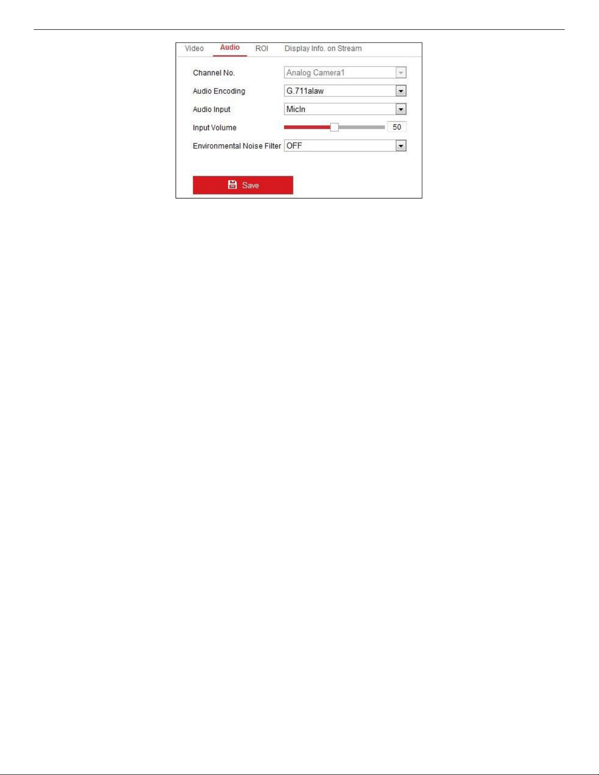
IP Network Camera User Manual
Figure 71, Audio Settings
2. Configure the following settings.
NOTE: Audio settings vary by camera model.
• Audio Encoding: G.722.1, G.711 ulaw, G.711 alaw, G.726, MP2L2, and PCM are selectable. For MP2L2,
the Sampling Rate and Audio Stream Bitrate are configurable. For PCM, the Sampling Rate can be
set.
• Audio Input: MicIn and LineIn are selectable for the connected microphone and pickup
respectively.
• Input Volume: 0−100 adjustable.
• Environmental Noise Filter: Set it to OFF or ON. When the function is enabled, the noise in the
environment can be filtered to some extent.
3. Click Save to save the settings.
8.1.4. Configuring ROI Encoding
Purpose
ROI (Region of Interest) encoding helps to discriminate between the ROI and background information in
video compression, which means the technology assigns more encoding resource to the region of
interest, thus increasing the quality of the ROI whereas the background information is less focused.
NOTE: The ROI function varies by camera model.
UM IP Network Camera 071619NA 75
Page 76

IP Network Camera User Manual
Figure 72, Region of Interest Settings
• Enter the ROI settings interface: Configuration > Video/Audio > ROI.
• Set the Stream Type for ROI encoding.
• Check the Enable checkbox under Fixed Region item.
• Set Fixed Region for ROI.
• Select the Region No. from the drop-down list.
• Check the Enable checkbox to enable ROI for the chosen region.
UM IP Network Camera 071619NA 76
Page 77
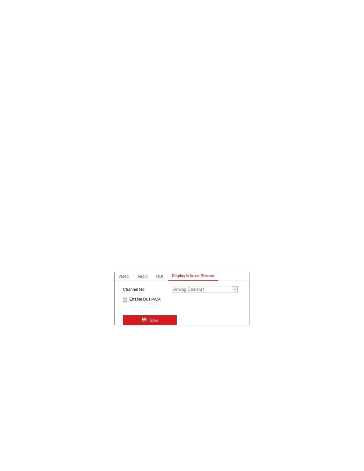
IP Network Camera User Manual
• Click Drawing. Click and drag the mouse on the view screen to draw a red rectangle as the ROI region.
You can click Clear to cancel former drawing. Click Stop Drawing when you finish.
• Select the ROI level.
• Enter a region name for the chosen region.
• Click Save to save the ROI settings for the chosen fixed region.
• Repeat steps (1) to (6) to setup other fixed regions.
• Set Dynamic Region for ROI.
• Check the checkbox to enable Face Tracking.
NOTE: To enable the face tracking function, the face detection function should be supported and
enabled.
• Select the ROI level.
• Click Save to save the settings.
NOTE: ROI level sets the image quality. The larger the value, the better the image quality.
8.1.5. Display Info. on Stream
Check the Enable Dual-VCA checkbox, and the object information (e.g., human, vehicle, etc.) will be
marked in the video stream. Then, you can set rules on the connected rear-end device to detect events,
including line crossing, intrusion, etc.
Figure 73, Display Info. on Stream
8.1.6. Configuring Target Cropping
Purpose
You can specify a target area on the live video, and the specified video area can be displayed via the third
stream in certain resolution, providing more details of the target area if needed.
NOTE: The target cropping function varies by camera model.
1. Enter the Target Cropping settings interface.
2. Check the Enable Target Cropping checkbox to enable the function.
UM IP Network Camera 071619NA 77
Page 78

IP Network Camera User Manual
3. Set Third Stream as the stream type.
4. Select the cropping resolution for the target area video display. A red rectangle is displayed on the live
video to mark the target area, and you can click-and-drag the rectangle to locate the target area as
desired.
5. Click Save to save the settings.
UM IP Network Camera 071619NA 78
Page 79
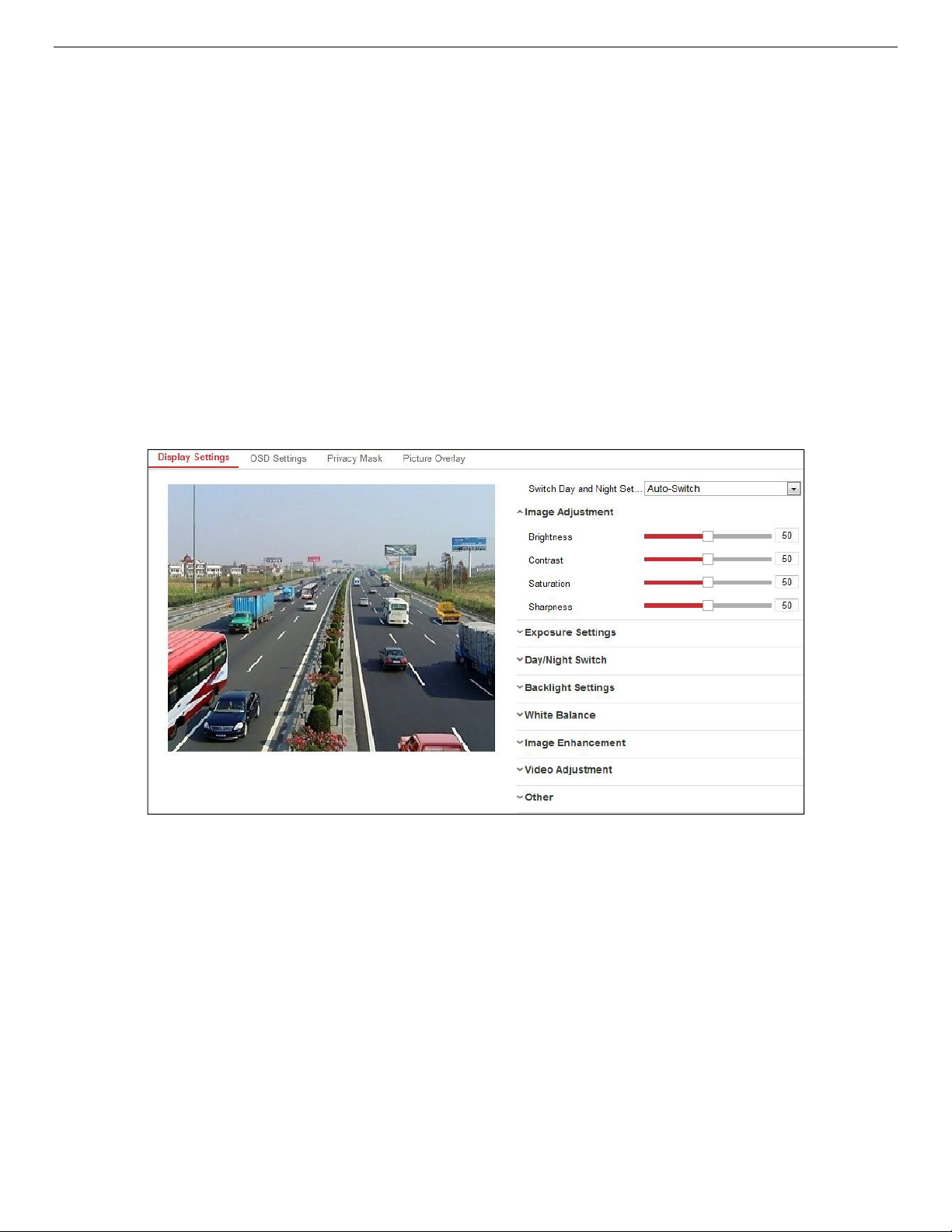
IP Network Camera User Manual
Chapter 9. Image Settings
Follow the instructions in this chapter to configure the image parameters, including display settings, OSD
settings, privacy mask, and picture overlay.
9.1. Configuring Display Settings
Purpose
Configure the image adjustment, exposure settings, day/night switch, backlight settings, white balance,
image enhancement, video adjustment, and other parameters in display settings.
NOTE: The display parameters vary by camera model. Please refer to the actual interface for details.
9.1.1. Day/Night Auto-Switch
1. Enter the Display Settings interface, Configuration > Image > Display Settings.
Figure 74, Display Settings of Day/Night Auto-Switch
2. Set the camera image parameters.
NOTE: In order to guarantee the image quality in different illumination, there are two sets of
parameters for users to configure.
9.1.1.1. Image Adjustment
• Brightness describes brightness of the image, which ranges from 1 to 100.
• Contrast describes the contrast of the image, which ranges from 1 to 100.
• Saturation describes the colorfulness of the image color, which ranges from 1 to 100.
• Sharpness describes the edge contrast of the image, which ranges from 1 to 100.
UM IP Network Camera 071619NA 79
Page 80

IP Network Camera User Manual
9.1.1.2. Exposure Settings
If the camera is equipped with a fixed lens, only Manual is selectable and the iris mode is not configurable.
If Auto is selected, you can set the auto iris level from 0 to 100.
Exposure Time refers to the electronic shutter speed, which ranges from 1 to 1/100,000s. Adjust it
according to the actual luminance condition.
Gain can also be manually configured from 0 to 100. The bigger the value, the brighter the image, and the
noise would also be amplified to a larger extent.
Figure 75, Exposure Settings
9.1.1.3. Focus
For cameras with a motor-driven lens, you can set the focus mode as Auto, Manual, or Semi-auto.
• Auto: Camera focus is adjusted automatically according to the actual monitoring scenario.
• Manual: You can control the lens by adjusting the zoom, focus, lens initialization, and auxiliary focus
manually.
• Semi-Auto: Camera will focus automatically when you adjust the zoom parameters.
9.1.1.4. Day/Night Switch
Select the Day/Night Switch mode according to different surveillance demand. Day, Night, Auto,
Scheduled-Switch, and Triggered by alarm input are selectable for day/night switch.
Figure 76, Day/Night Switch
• Day: Camera stays in day mode
• Night: Camera stays in night mode
• Auto: Camera switches between day mode and night mode according to the illumination automatically.
The sensitivity ranges from 0 to 7. The higher the value, the easier the mode switches.
UM IP Network Camera 071619NA 80
Page 81

IP Network Camera User Manual
• Filtering Time: The interval time between the day/night switch. You can set it from 5s to 120s.
• Scheduled-Switch: Set the start time and the end time to define the duration for day/night mode.
• Triggered by alarm input: The switch is triggered by alarm input. You can set the triggered mode to day
or night.
• Smart Supplement Light: Set the supplement light to ON, and Auto and Manual are selectable.
- Auto − Supplement light changes according to the actual luminance. E.g., if the current scene is
bright enough, then the supplement light adjusts itself to a lower power, and if the scene is not
bright enough, the light adjusts itself to a higher power.
- Manual − You can adjust the supplement by adjusting the distance. E.g., if the object is near the
camera, the device adjusts the supplement light to lower power, and the light is in higher power if
the object is far away.
9.1.1.5. Backlight Settings
• BLC Area: If you focus on an object against a strong backlight, the object will be too dark to be seen
clearly. BLC compensates light to the object in the front to make it clear. OFF, Up, Down, Left, Right,
Center, Auto, and Custom are selectable.
NOTE: If BLC mode is set as Custom, you can draw a red rectangle on the live view image as the BLC
area.
• WDR: Wide Dynamic Range can be used when there is a high contrast between the scene’s bright area
and dark area.
• HLC: High Light Compression function can be used when there are strong lights in the scene affecting
the image quality.
9.1.1.6. White Balance
White balance is the white rendition function of the camera used to adjust the color temperature
according to the environment.
Figure 77, White Balance
UM IP Network Camera 071619NA 81
Page 82

IP Network Camera User Manual
9.1.1.7. Image Enhancement
• Digital Noise Reduction: DNR reduces the noise in the video stream. OFF, Normal, and Expert are
selectable. Set the DNR level from 0 to 100 in Normal Mode. Set the DNR level from both space DNR level
[0−100] and time DNR level [0-100] in Expert Mode.
• Defog Mode: You can enable the defog function when the environment is foggy and the image is misty.
It enhances subtle details so that the image appears clearer.
• EIS (Electrical Image Stabilizer): EIS reduces the effects of vibration in a video.
• Grey Scale: You can choose the range of the grey scale as [0−255] or [16−235].
9.1.1.8. Video Adjustment
• Mirror: It mirrors the image so you can see it inversed. Left/Right, Up/Down, Center, and OFF are
selectable.
• Rotate: To make a complete use of the 16:9 aspect ratio, you can enable the rotate function when you
use the camera in a narrow view scene.
When installing, turn the camera 90 degrees or rotate the 3-axis lens to 90 degrees, and set the rotate
mode as on, you will get a normal view of the scene with 9:16 aspect ratio to ignore needless
information such as the wall, and get more meaningful information of the scene.
• Scene Mode: Choose the scene as indoor or outdoor according to the real environment.
• Video Standard: 50 Hz and 60 Hz are selectable. Choose according to the different video standards,
normally 50 Hz for PAL standard and 60 Hz for NTSC standard.
• Lens Distortion Correction: For cameras equipped with a motor-driven lens, image may appear
distorted to some extent. Turn on this function to correct the distortion.
• Others: Some camera models support CVBS, SDI, or HDMI output. Set the local output ON or OFF
according to the actual device.
9.1.2. Day/Night Scheduled-Switch
The Day/Night scheduled-switch configuration interface allows you to set the camera parameters for day
and night separately, guaranteeing the image quality in different illumination.
UM IP Network Camera 071619NA 82
Page 83

IP Network Camera User Manual
Figure 78, Day/Night Scheduled-Switch Configuration Interface
1. Click the calendar icon to select the start time and the end time of the switch.
NOTES: The start time and end time refer to the valid time for day mode.
The time period can start and end on two days in a row. For example, if you set start time as
10:00 and end time as 1:00, the day mode will be activated at 10 o'clock in the morning and
stopped at 1 o'clock early in the next morning.
2. Click the Common tab to configure the common parameters applicable to day mode and night mode.
NOTE: For the detailed information of each parameter, refer to
Section 9.1.1 Day/Night Auto-Switch.
3. Click the Day tab to configure the parameters applicable for day mode.
4. Click the Night tab to configure the parameters applicable for night mode.
NOTE: The settings are saved automatically if any parameter is changed.
9.1.3. Configuring OSD Settings
Purpose
You can customize the camera name, time/date format, display mode, and OSD size displayed on the live
view.
UM IP Network Camera 071619NA 83
Page 84

IP Network Camera User Manual
Figure 79, OSD Settings
1. Enter the OSD Settings interface: Configuration > Image > OSD Settings.
2. Check the corresponding checkbox to select the display of camera name, date, or week if required.
3. Edit the camera name in the Camera Name text field.
4. Select from the drop-down list to set the time format and date format.
5. Select from the drop-down list to set the time format, date format, display mode, OSD size, and OSD
color.
6. Configure the text overlay settings.
1) Check the checkbox in front of the textbox to enable the on-screen display.
2) Input the characters in the textbox.
NOTE: Up to eight text overlays are configurable.
7. Adjust the position and alignment of text frames.
• Left align, right align, and custom are selectable. If you select custom, you can use the mouse to
click and drag text frames in the live view window to adjust their positions.
NOTE: The alignment adjustment is applicable only to Text Overlay items.
8. Click Save to save the settings.
UM IP Network Camera 071619NA 84
Page 85

IP Network Camera User Manual
9.1.4. Configuring Privacy Mask
Purpose
Privacy mask enables you to cover certain areas on the live video to prevent certain spots in the
surveillance area from being live viewed and recorded.
1. Enter the Privacy Mask Settings interface: Configuration > Image > Privacy Mask.
2. Check the Enable Privacy Mask checkbox to enable this function.
3. Click Draw Area.
Figure 80, Privacy Mask Settings
4. Click and drag the mouse in the live video window to draw the mask area.
NOTE: You are allowed to draw up to four areas on the same image.
5. Click Stop Drawing to finish drawing or click Clear All to clear all areas you set without saving them.
6. Click Save to save the settings.
9.1.5. Configuring Picture Overlay
Purpose
Picture overlay allows you to overlay a picture on the image. This function enables a certain enterprise or
users to overlay their logo on the image.
1. Enter the Picture Overlay Settings interface, Configuration > Image > Picture Overlay.
UM IP Network Camera 071619NA 85
Page 86

IP Network Camera User Manual
2. Click Browse to select a picture.
Figure 81, Picture Overlay
3. Click Upload to upload it.
4. Check the Enable Picture Overlay checkbox to enable the function.
5. Set X Coordinate and Y Coordinate values to adjust the picture position on the image. Adjust Picture
Width and Picture Height to the desired size.
6. Click Save to save settings.
NOTE: The picture must be in RGB24 bmp format and the maximum picture size is 128*128.
UM IP Network Camera 071619NA 86
Page 87

IP Network Camera User Manual
Chapter 10. Event Settings
This section explains how to configure the network camera to respond to alarm events, including basic
events and smart events.
10.1. Basic Events
You can configure events by following the instructions in this section, including motion detection, video
tampering, alarm input, alarm output, exception, etc. These events can trigger linkage methods such as
Notify Surveillance Center, Send Email, Trigger Alarm Output, etc.
NOTE: Check the Notify Surveillance Center checkbox if you want the alarm information to be pushed
to a PC or mobile client software as soon as the alarm is triggered.
10.1.1. Configuring Motion Detection
Purpose
Motion detection detects moving objects in the configured surveillance area, and a series of actions can
be taken when the alarm is triggered.
In order to detect the moving objects accurately and reduce the false alarm rate, normal configuration
and expert configuration are selectable for different motion detection environments.
• Normal Configuration
Normal configuration adopts the same set of motion detection parameters in the day and at night.
˗ Task 1: Set the Motion Detection Area Steps
1. Enter the motion detection settings interface: Configuration > Event > Basic Event > Motion
Detection.
2. Check the Enable Motion Detection checkbox.
3. Check the Enable Dynamic Analysis for Motion checkbox to show detected objects with green
rectangles.
NOTE: Select Disable for Rules if you don’t want the detected objects displayed with green rectangles.
Select disable rules from Configuration > Local Configuration > Live View Parameters-rules.
UM IP Network Camera 071619NA 87
Page 88

IP Network Camera User Manual
Figure 82, Enable Motion Detection
4. Click Draw Area. Click and drag the mouse on the live video to draw a motion detection area.
Click Stop Drawing to finish drawing one area.
5. (Optional) Click Clear All to clear all of the areas.
6. (Optional) Move the slider to set the sensitivity of the detection.
˗ Task 2: Set the Arming Schedule for Motion Detection
UM IP Network Camera 071619NA 88
Page 89

IP Network Camera User Manual
Figure 83, Arming Schedule
1. Click Arming Schedule to edit the arming schedule.
2. Click on the time bar and drag the mouse to select the time period.
Figure 84, Arming Schedule
NOTE: Click on the selected time period, and you can adjust the time period to the desired time by
either moving the time bar or inputting the exact time period.
3. (Optional) Click Delete to delete the current arming schedule, or click Save to save the settings.
4. Move the mouse to the end of each day, a copy dialogue box pops up, and you can copy the
current settings to other days.
UM IP Network Camera 071619NA 89
Page 90

IP Network Camera User Manual
5. Click Save to save the settings.
NOTE: The time of each period can’t overlap. Up to eight periods can be configured for each day.
˗ Task 3: Set the Linkage Method for Motion Detection
Check the checkbox to select the linkage method. Audible Warning, Send Email, Notify Surveillance
Center, Upload to FTP/Memory Card/NAS, Trigger Channel, and Trigger Alarm Output are selectable.
You can specify the linkage method when an event occurs.
Figure 85, Linkage Method
NOTE: The linkage methods vary by camera model.
• Audible Warning: Trigger the audible warning locally. Supported only by devices that have audio
output.
• Notify Surveillance Center: Send an exception or alarm signal to remote management software
when an event occurs.
• Send Email: Send an e-mail with alarm information to a user or users when an event occurs.
NOTE: To send the e-mail when an event occurs, refer to
Section 7.2.3, Configuring E-Mail Settings
complete e-mail setup in advance.
• Upload to FTP/Memory Card/NAS: Capture the image when an alarm is triggered and upload the
picture to a FTP server.
NOTES: Set the FTP address and the remote FTP server first. Refer to
Settings
for detailed information.
to
Section 7.2.2, Configuring FTP
Go to Configuration > Storage > Schedule Settings> Capture > Capture Parameters, enable the
event-triggered snapshot, and set the capture interval and capture number.
The captured image can also be uploaded to an available SD card or network disk.
• Trigger Channel: The video will be recorded when motion is detected. You must set the recording
schedule to realize this function. Refer to
Section 11.1
for detailed information.
• Trigger Alarm Output: Trigger one or more external alarm outputs when an event occurs.
UM IP Network Camera 071619NA 90
Page 91

IP Network Camera User Manual
NOTE: To trigger an alarm output when an event occurs, refer to
Output
to set the related parameters.
Section 10.1.4, Configuring Alarm
• Expert Configuration: Expert mode is used mainly to configure the sensitivity and proportion of object
on each area for different day/night switch.
Figure 86, Expert Mode of Motion Detection
˗ Day/Night Switch OFF
1. Draw the detection area as in the normal configuration mode. Up to eight areas are supported.
2. Select OFF for Switch Day and Night Settings.
3. Select the area by clicking the area no.
4. Slide the cursor to adjust the sensitivity and proportion of object on the area for the selected
area.
5. Set the arming schedule and linkage method as in the normal configuration mode.
6. Click Save to save the settings.
˗ Day/Night Auto-Switch
1. Draw the detection area as in the normal configuration mode. Up to eight areas are supported.
2. Select Auto-Switch for Switch Day and Night Settings.
3. Select the area by clicking the area no.
4. Slide the cursor to adjust the sensitivity and proportion of object on the area for the selected
area in the daytime.
5. Slide the cursor to adjust the sensitivity and proportion of object on the area for the selected
area at night.
UM IP Network Camera 071619NA 91
Page 92

IP Network Camera User Manual
6. Set the arming schedule and linkage method as in the normal configuration mode.
7. Click Save to save the settings.
˗ Day/Night Scheduled-Switch
1. Draw the detection area as in the normal configuration mode. Up to eight areas are supported.
2. Select Scheduled-Switch for Switch Day and Night Settings.
3. Select the start time and the end time for the switch timing.
Figure 87, Day/Night Scheduled-Switch
4. Select the area by clicking the area no.
5. Slide the cursor to adjust the sensitivity and proportion of object on the area for the selected
area in the daytime.
6. Slide the cursor to adjust the sensitivity and proportion of object on the area for the selected
area at night.
7. Set the arming schedule and linkage method as in the normal configuration mode.
8. Click Save to save the settings.
10.1.2. Configuring Video Tampering Alarm
Purpose
You can configure the camera to trigger an alarm when the lens is covered and take certain alarm
response actions.
Detection area for this alarm is the whole screen.
1. Enter the Video Tampering Settings interface, Configuration > Event > Basic Event > Video Tampering.
2. Check the Enable Video Tampering checkbox to enable video tampering detection.
3. Click Edit to edit the video tampering arming schedule. The arming schedule configuration is the same
as setting the motion detection arming schedule. Refer to
Detection
4. Check the checkbox to select the linkage method taken for the video tampering. Refer to
the Linkage Method for Motion Detection
5. Click Save to save the settings.
UM IP Network Camera 071619NA 92
in
Section 10.1.1.
in
Section 10.1.1.
Task 2: Set the Arming Schedule for Motion
Task 3: Set
Page 93

IP Network Camera User Manual
10.1.3. Configuring Alarm Input
1. Enter the Alarm Input Settings interface: Configuration > Event > Basic Event > Alarm Input.
2. Choose the alarm input no. and the Alarm Type. The alarm type can be NO (Normally Open) and NC
(Normally Closed). Edit the name to set a name for the alarm input (optional).
Figure 88, Alarm Input Settings
3. Click Arming Schedule to set the arming schedule for the alarm input. Refer to
Schedule for Motion Detection
4. Click Linkage Method and check the checkbox to select the linkage method taken for the alarm input.
Refer to
5. You can copy your settings to other alarm inputs.
6. Click Save to save the settings.
Task 3: Set the Linkage Method for Motion Detection
in
Section 10.1.1.
in
Section 10.1.1.
Task 2: Set the Arming
UM IP Network Camera 071619NA 93
Page 94

IP Network Camera User Manual
10.1.4. Configuring Alarm Output
Figure 89, Alarm Output Settings
1. Enter the Alarm Output Settings interface: Configuration> Event > Basic Event > Alarm Output.
2. Select one alarm output channel in the Alarm Output drop-down list. You can also set a name for the
alarm output (optional).
3. The Delay time can be set to 5 sec, 10 sec, 30 sec, 1 min, 2 min, 5 min, 10 min, or Manual. The delay
time refers to the time duration that the alarm output remains in effect after alarm occurs.
4. Click Arming Schedule to enter the Edit Schedule Time interface. The time schedule configuration is
the same as the settings of the arming schedule for motion detection. Refer to
Schedule for Motion Detection
5. You can copy the settings to other alarm outputs.
6. Click Save to save the settings.
in
Section 10.1.1.
Task 2: Set the Arming
10.1.5. Handling Exception
The exception type can be HDD full, HDD error, network disconnected, IP address conflicted, and illegal
login to the cameras.
1. Enter the Exception Settings interface: Configuration > Event > Basic Event > Exception.
2. Check the checkbox to set the actions taken for the Exception alarm. Refer to
Method
UM IP Network Camera 071619NA 94
for Motion Detection
in
Section 10.1.1.
Task 3: Set the Linkage
Page 95

IP Network Camera User Manual
3. Click Save to save the settings.
10.1.6. Configuring Other Alarms
NOTE: Certain cameras support wireless alarms, PIR (passive infrared sensor) alarms, or emergency
alarms.
10.1.6.1. Wireless Alarm
Purpose
When a wireless alarm signal is sent to the camera from a detector such as a wireless door contact, the
wireless alarm is triggered and a series of response actions can be taken.
1. Enter the Wireless Alarm Settings interface, Configuration > Advanced Configuration > Basic Event >
Wireless Alarm.
Figure 90, Setting Wireless Alarm
2. Select the wireless alarm number. Up to eight channels of external wireless alarm input are supported.
3. Check the Enable Wireless Alarm checkbox to activate the wireless alarm.
4. Input the alarm name in the text field as desired.
5. Check the checkbox to select the linkage methods taken for the wireless alarm.
6. Click Save to save the settings.
7. Locate the external wireless device beside the camera, and go to Configuration > System > System
Settings > Remote Control to arm the camera and study the wireless alarm.
UM IP Network Camera 071619NA 95
Page 96

IP Network Camera User Manual
Figure 91, Configuring Wireless Alarm Settings
10.1.6.2. PIR Alarm
Purpose
A PIR (Passive Infrared) alarm is triggered when an intruder moves within the detector’s field of view. The
heat energy dissipated by a person, or any other warm blooded creature such as dogs, cats, etc., can be
detected.
1. Enter the PIR Alarm Settings interface, Configuration > Advanced Configuration> Basic Event> PIR
Alarm.
Figure 92, Setting PIR Alarm
2. Check the Enable checkbox to activate the PIR alarm function.
3. Input the alarm name in the text field as desired.
4. Check the checkbox to select the linkage methods for the PIR alarm.
5. Click the Edit button to set the arming schedule.
UM IP Network Camera 071619NA 96
Page 97

IP Network Camera User Manual
6. Click Save to save the settings.
7. Go to Configuration > Advanced Configuration> System> Remote Control to arm the camera.
Figure 93, Arming PIR Alarm
10.1.6.3. Emergency Alarm
Purpose
You can press the Emergency button on the remote control to trigger the Emergency Alarm in case of an
emergency.
NOTE: The remote control is required for the Emergency Alarm. Go to Configuration > System> System
Settings > Remote Control to study the remote control first.
1. Enter the Emergency Alarm Settings interface, Configuration > Event > Basic Event > Emergency Alarm.
Figure 94, Setting Emergency Alarm
2. Check the checkbox to select the linkage methods for the Emergency alarm.
3. Click Save to save the settings.
10.2. Smart Events
You can configure the smart events by following the instructions in this section, including audio
exception detection, defocus detection, scene change detection, intrusion detection, line crossing
detection, etc. These events can trigger linkage methods such as Notify Surveillance Center, Send Email,
Trigger Alarm Output, etc.
UM IP Network Camera 071619NA 97
Page 98

IP Network Camera User Manual
NOTE: DS-2CD2xx6G1 Series Cameras Only: Some Smart VCA functions (line crossing detection,
intrusion detection, region entrance/exit detection) are not functional when using third video
stream, H.265+ video compression, or motion detection.
10.2.1. Configuring Audio Exception Detection
Purpose
The Audio Exception detection function detects abnormal sounds in the surveillance scene such as
sudden increase/decrease in sound intensity, and certain actions can be taken when the alarm is
triggered.
NOTE: The Audio Exception detection function varies by camera model.
1. Enter the Audio Exception Detection settings interface, Configuration > Event > Smart Event > Audio
Exception Detection.
Figure 95, Audio Exception Detection
2. Check the Audio Loss Exception checkbox to enable the Audio Loss detection function.
3. Check the Sudden Increase of Sound Intensity Detection checkbox to detect a steep rise in the
surveillance scene’s sound. You can set the detection sensitivity and threshold.
4. Check the Sudden Decrease of Sound Intensity Detection checkbox to detect a steep drop in the
surveillance scene’s sound. You can set the detection sensitivity and threshold.
NOTES: Sensitivity: Range [1−100], the smaller the value, the more severe the change must be to
trigger the detection.
Sound Intensity Threshold: Range [1−100], can filter environment sound, the louder the
environment sound, the higher the value must be. Adjust it according to the real environment.
You can view the real-time sound volume on the interface.
UM IP Network Camera 071619NA 98
Page 99
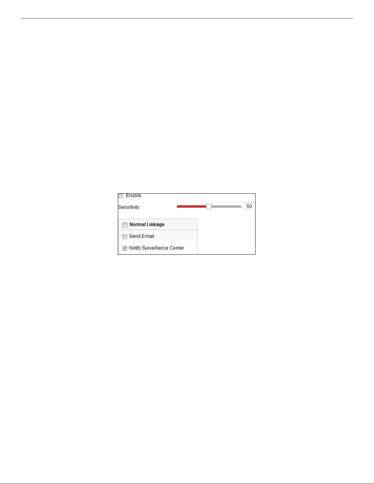
IP Network Camera User Manual
5. Click Arming Schedule to set the arming schedule. Refer to
Detection
6. Click Linkage Method and select the linkage methods for audio exception, including Notify Surveillance
Center, Send Email, Upload to FTP/Memory Card/NAS, Trigger Channel for recording, and Trigger Alarm
Output.
7. Click Save to save the settings.
in
Section 10.1.1
for detailed steps
.
Task 2 Set the Arming Schedule for Motion
10.2.2. Configuring Defocus Detection
Purpose
The image blur caused by lens defocus can be detected, and certain actions can be taken when the alarm
is triggered.
NOTE: The Defocus Detection function varies by camera model.
1. Enter the Defocus Detection settings interface, Configuration > Event > Smart Event > Defocus
Detection.
Figure 96, Configuring Defocus Detection
2. Check the Enable checkbox to enable the function.
3. Click-and-drag the slider to set the detection sensitivity. The sensitivity value ranges from 1 to 100,
and the higher the value, the more easily the defocus image will trigger the alarm.
4. Select the linkage method for defocus, including Notify Surveillance Center, Send Email, and Trigger
Alarm Output.
5. Click Save to save the settings.
10.2.3. Configuring Scene Change Detection
Purpose
Scene Change Detection detects the change of the surveillance environment affected by external factors
such as intentional rotation of the camera. Certain actions can be taken when the alarm is triggered.
NOTE: The Scene Change Detection function varies by camera model.
1. Enter the Scene Change Detection settings interface, Configuration > Event > Smart Event > Scene
Change Detection.
UM IP Network Camera 071619NA 99
Page 100

IP Network Camera User Manual
2. Check the Enable checkbox to enable the function.
Figure 97, Scene Change Detection
3. Click-and-drag the slider to set the detection sensitivity. The sensitivity value ranges from 1 to 100,
and the higher the value, the more easily the change of scene will trigger the alarm.
4. Click Arming Schedule to set the arming schedule. Refer to
Detection
5. Click Linkage Method to select the linkage method for scene change, including Notify Surveillance
Center, Send Email, Upload to FTP/Memory Card/NAS, Trigger Channel, and Trigger Alarm Output.
6. Click Save to save the settings.
in
Section 10.1.1
for detailed steps
.
Task 2: Set the Arming Schedule for Motion
10.2.4. Configuring Face Detection
Purpose
The Face Detection function detects faces that appear in the surveillance scene, and certain actions can
be taken when the alarm is triggered.
1. Enter the Face Detection settings interface, Configuration > Event > Smart Event > Face Detection.
2. Check the Enable Face Detection checkbox to enable the function.
3. Check the Enable Dynamic Analysis checkbox for Face Detection, and then a detected face will be
marked with a green rectangle on the live video.
NOTE: To mark the detected face on the live video, go to Configuration > Local to enable the Rules.
4. Click-and-drag the slider to set the detection sensitivity. The Sensitivity ranges from 1 to 5. The higher
the value, the more easily the face will be detected.
5. Click Arming Schedule to set the arming schedule. Refer to
Detection
UM IP Network Camera 071619NA 100
in
Section 10.1.1
for detailed steps
.
Task 2: Set the Arming Schedule for Motion
 Loading...