

Page 1

OPERATOR’S
MANUAL
VELOCITY SERIESTM PRESSURE FRYER
MODEL
PXE-100
REGISTER WARRANTY ONLINE AT WWW.HENNYPENNY.COM
REGISTER WARRANTY ONLINE AT WWW.HENNYPENNY.COM
Read instructions before operating the applianceOriginal Instructions
Page 2

Page 3

HENNY PENNY
ELECTRIC PRESSURE FRYER
SPECIFICATIONS
Pot Capacity 8 head of chicken - 24 lbs. (10.8 kg)
76 lbs. oil (34 Kg.)
Electrical 208 VAC, 3 Phase, 50/60 Hz, 17 KW, 47.2 Amps
240 VAC, 3 Phase, 50/60 Hz, 17 KW, 40.9 Amps
480 VAC, 3 Phase, 50/60 Hz, 17 KW, 20.5 Amps
Heating Two 8,500 watt electric immersion elements
A data plate, located on the back shroud behind the lid identies the fryer model, serial
number, warranty date, and other information. Also, the serial number is stamped on the
outside of the counter top. See gure below.
Serial No.
Page 4

PXE-100
DIMENSIONS
Page 5

HENNY PENNY
8 HEAD ELECTRIC PRESSURE FRYER
Fryer must be installed and used in such a way to prevent water from contacting the shortening.
This appliance is not intended to be operated by means of an external timer or a separate remote control
system.
This appliance is not intended for use by persons (including children) with reduced physical, sensory or
mental capabilities, or lack of experience and knowledge, unless they have been given supervision or
instruction concerning use of the appliance by a person responsible for their safety.
Page 6

TABLE OF CONTENTS
Section Page
Section 1. INTRODUCTION ..................................................................................................... 1
1-1 Safety ............................................................................................................. 1
1-2 Proper Care ....................................................................................................2
1-3 Assistance ...................................................................................................... 2
Section 2. INSTALLATION .......................................................................................................3
2-1 Introduction ................................................................................................... 3
2-2 Unpacking...................................................................................................... 3
2-3 Selecting the Fryer Location ......................................................................... 7
2-4 Leveling the Fryer ......................................................................................... 7
2-5 Ventilation of Fryer........................................................................................8
2-6 Electrical Requirements .................................................................................8
2-7 International Electrical Requirements ...........................................................9
Section 3. OPERATION .............................................................................................................11
3-1 Operating Components ..................................................................................11
3-2 Control Overview ..........................................................................................12
3-3 Display Options .............................................................................................14
3-4 4+Title Option ...............................................................................................14
3-5 5+Next Option ...............................................................................................15
3-6 6 Item Option .................................................................................................15
3-7 Drain Pan Assembly ...................................................................................... 16
3-8 Product Racking Recommendations ..............................................................17
3-9 Lid Operation.................................................................................................18
3-10 Start-up .......................................................................................................... 20
3-11 Filling the Oil Tank ........................................................................................ 21
3-12 Condensation T ank ........................................................................................21
3-13 Filter Pump Motor Protector-Manual Reset .................................................. 22
3-14 Regular Maintenance Schedule ..................................................................... 22
3-15 Initial Oil Fill ................................................................................................. 23
3-16 Basic Operation ............................................................................................. 24
3-17 Care of the Oil ............................................................................................... 25
3-18 Main Menu .................................................................................................... 25
3-19 Filtering Instructions ..................................................................................... 26
3-20 Bulk Dispose ................................................................................................. 30
3-21 Changing the Filter Envelope ........................................................................ 31
3-22 Clean-Out Mode ............................................................................................ 31
3-23 Preventive Maintenance ............................................................................... 36
Section 4. PROGRAMMING ........................................................................................................39
4-1 Program Menu ............................................................................................... 39
4-2 Product Programming ....................................................................................39
4-3 Special Programming ....................................................................................41
Section 5. TROUBLE SHOOTING ...............................................................................................44
5-1 Troubleshooting Guide ..................................................................................44
5-2 Error Codes ....................................................................................................45
Sept. 2014
Page 7

SECTION 1: INTRODUCTION
1-1
SAFETY
The instructions in this manual have been prepared to aid you in learning
the proper procedures for your equipment. Where information is of
particular importance or is safety related, the words NOTICE, CAUTION,
or WARNING are used. Their usage is described below.
If a problem occurs during the rst operation of a new unit, recheck the
Installation Section of the Operator’s Manual.
Before troubleshooting, always recheck the Operation
Section of the Operator’s Manual.
Where information is of particular importance or is safety related, the
words DANGER, WARNING, CAUTION, or NOTICE are used. Their
usage is described as follows:
SAFETY ALERT SYMBOL is used with DANGER, WARNING
or CAUTION which indicates a personal injury type hazard.
NOTICE is used to highlight especially important information.
CAUTION used without the safety alert symbol indicates a
potentially hazardous situation which, if not avoided, may result
in property damage.
CAUTION used with the safety alert symbol indicates a
potentially hazardous situation which, if not avoided, could result
in minor or moderate injury.
WARNING indicates a potentially hazardous situation which,
if not avoided, could result in death or serious injury.
DANGER INDICATES AN IMMINENTLY HAZARDOUS
SITUATION WHICH, IF NOT AVOIDED, WILL RESULT IN
DEATH OR SERIOUS INJURY.
March 2014
1
Page 8

1-1.
SAFETY
(CONT.)
Equipotential Ground Symbol
Waste Electrical and Electronic Equipment (WEEE) Symbol
1-2.
PROPER CARE
OR
OR
Shock Hazard Symbols
Hot Surface Symbols
As in all Henny Penny equipment, the unit requires care and
maintenance. Requirements for maintenance and cleaning are
contained in this manual and must be a regular part of the operation of the unit.
1-3.
ASSISTANCE
March 2014
Should you require outside assistance, call your local distributor in your area, or call 1-800-417-8405 or 1-937-456-8405.for
Henny Penny Technical Support.
2
Page 9

SECTION 2: UNPACKING / INSTALLATION
2-1.
INTRODUCTION
2-2.
UNPACKING
This section provides the installation and unpacking instructions.
• Any shipping damage should be noted in the
presence of the delivery agent and signed prior to
his or her departure.
• Installation of this unit should be performed only
by a qualied service technician.
• Take care when moving the fryer to
prevent personal injury. The fryer weighs
approximately 877 lbs.(398 Kg).
• Do not puncture the fryer with any objects
such as drills or screws as electrical shock or
component damage could result.
March 2014
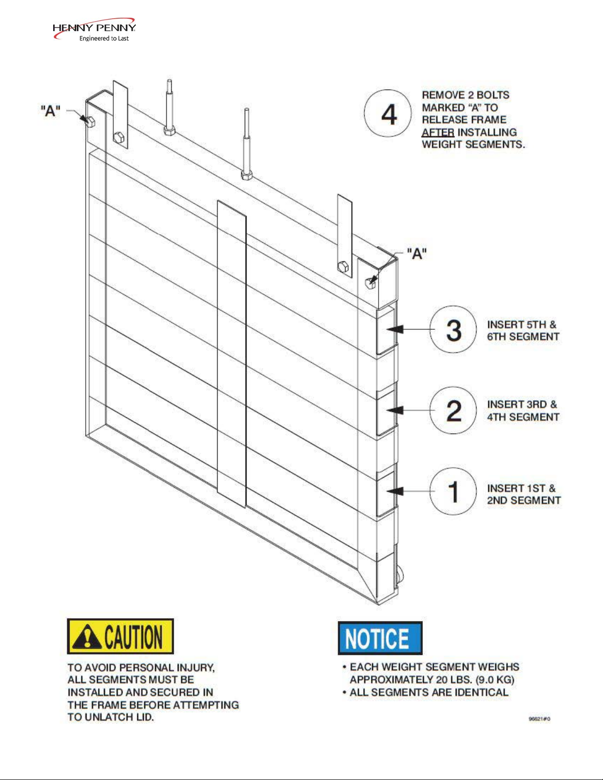
To avoid personal injury, all counter-weights must be
installed and secured before attempting to unlatch
the lid.
1. Cut and remove the plastic bands from the main box.
2. Remove the box lid and lift the main box off the fryer.
3. Remove corner packing supports (4).
4. Cut the stretch lm from around the carrier/rack box and
remove it from the top of the fryer lid.
5. Cut and remove the metal bands holding the fryer to the
pallet.
6. Remove the fryer from the pallet. See one unloading
method described on 6.
3
Page 10

2-2.
UNPACKING
(CONT.)
Do not drop counterweights , or personal injury could
result. Each counterweight weighs approximately
20 lbs. (9 kg.) each.
7. Remove the counterweights from the pallet, which are strapped
to the pallet, under the fryer.
8. Remove rear service cover.
9. Load the six weights into the counterweight assembly. See
page 7.
10. Replace rear service cover.
To avoid personal injury and assure safe
operation of unit, rear service cover must
be in place.
11. Cut warning tags from the lid assembly. The lid may now be
unlatched.
12. Remove the accessories from inside the lter drain pan.
13. Remove the protective paper from the fryer cabinet. Clean
exterior surface with a damp cloth.
March 2014
4
Page 11

Ramp Unloading
1. Front casters are xed in the forward position.
2. Pry off the rail on either side of the pallet.
3. Prop up a ramp for each caster on the selected side.
If ramp is not being used, rest the selected side’s casters onto the ground and move to step 4.
4. Tilt and roll the unit off the pallet onto the ramp (if available). The front casters will slide onto the ramp.
Pull the pallet from under the unit and set the unit onto the ground.
5. Remove the weights from the pallet.
6. Remove the rear cover. The weight segments must be installed per instructions contained therein before attempting to
unlatch the lid.
Dec. 2013
5
Page 12
Dec. 2013
6
Page 13

2-3.
SELECTING THE
LOCATION
The proper location of the fryer is very important for operation, speed,
and convenience. Choose a location which provides easy loading and
unloading without interfering with the nal assembly of food orders.
Operators nd that frying from raw to nish, and holding the product
in a warmer provides fast continuous service. Landing or dumping
tables should be provided next to the fryer. The best efciency will be
obtained by a straight line operation, i.e. raw in one side and nish out
the other side. Order assembly can be moved away with only a slight
loss of efciency.
To properly service the fryer, 24 inches (60.96 cm) of clearance is
needed on all sides of the fryer. Access for servicing by removing a
side panel.
To avoid re and ruined supplies, the area under the
fryer should not be used to store supplies.
2-4.
LEVELING THE
FRYER
To prevent severe burns from splashing hot oil, position
and install fryer to prevent tipping or movement.
Restraining ties may be used for stabilization.
For proper operation, level the fryer from side to side and front to back.
Use level on the at areas around the frypot collar.
F AILURE T O FOLLOW THESE LEVELING
INSTRUCTIONS CAN RESULT IN OIL
OVERFLOWING THE FRYPOT WHICH COULD
CAUSE SERIOUS BURNS, PERSONAL INJURY,
FIRE AND/OR PROPERTY DAMAGE.
March 2014
7
Page 14

2-5.
VENTILATION OF
FRYER
The fryer should be located with provision for venting into adequate exhaust
hood or ventilation system to permit efcient removal of steam exhaust and
frying odors. The exhaust canopy must be designed to avoid interference
with the operation of the fryer. Consult a local ventilation or heating
company to help in designing an adequate system.
Ventilation must conform to local, state,
and national codes. Consult your local re
department or building authorities.
2-6.
ELECTRICAL
REQUIREMENTS
The electric fryer requires 208, 240 or 480 volt, three phase, 50/60 Hertz
service. The power cord may be already attached to the fryer, or provided at
installation. Check the data plate to determine the correct power supply.
This fryer must be adequately and safely grounded (earthed) or
electrical shock could result. Refer to local electrical codes for
correct grounding (earthing) procedures or in absence of local codes,
with The National Electrical Code, ANSI/NFPA No. 70-(the current
edition). In Canada, all electrical connections are to be made in
accordance with CSA C22.1, Canadian Electrical Code Part 1, and/or
local codes. To avoid electrical shock, this appliance must be equipped
with an external circuit breaker which will disconnect all ungrounded
(unearthed) conductors. The main power switch on this appliance
does not disconnect all line conductors
A separate disconnect switch meeting overvoltage category III conditions
with proper capacity fuses or breakers must be installed at a convenient
location between the fryer and the power source. It should be an insulated
copper conductor rated for 600 volts and 90o C. For runs longer than 50 feet
(15.24 m), use the next larger wire size.
Aug. 2014
8
Page 15

2-7.
INTERNATIONAL
ELECTRICAL
REQUIREMENTS
Units being used outside the United States may not be shipped with the
power cord attached to the unit because of the different wiring codes.
The fryers are available from the factory wired for 200, 240, 380 and
415 volts, 3 phase, 50 Hertz service. A terminal block is mounted
inside the fryer for the cable wiring.
• CE units require a minimum wire size of 4mm to be wired to
the terminal block. If a exible power cord is used, it must be
HO7RN type.
• The supply power cords shall be oil-resistant, sheathed exible
cable, no lighter than ordinary polychloroprene or other
equivalent synthetic elastomer-sheathed cord.
• It is recommended that a 30 mA rated protective device such
as a residual current circuit breaker (RCCB), or ground fault
circuit interrupter (GFCI), be used on the fryer circuit.
(FOR EQUIPMENT WITH CE MARK ONLY!) To prevent electric
shock hazard this appliance must be bonded to other appliances or
touchable metal surfaces in close proximity to this appliance with an
equipotential bonding conductor. This appliance is equipped with an
equipotential lug for this purpose. The equipotential lug is marked
with the following symbol
March 2014
9
Page 16

BOIL-OVER PREVENTION IN HENNY PENNY FRYER
FAILURE TO FOLLOW THESE INSTRUCTIONS CAN RESULT
IN OIL OVERFLOWING THE FRYPOT WHICH COULD CAUSE SERIOUS
BURNS, PERSONAL INJURY, FIRE AND/OR PROPERTY DAMAGE.
• THE OIL MAY BE STIRRED ONLY DURING THE MORNING START UP
PROCEDURE. DO NOT STIR THE OIL AT ANY OTHER TIME.
• BRUSH ALL CRACKLINGS FROM FRYPOT SURFACES DURING THE
POT CLEAN OUT PROCESS.
• MAKE SURE THE FRYER IS LEVEL.
• BE CERTAIN THE OIL IS NEVER ABOVE THE UPPER FRYPOT “FILL”
LINE.
• BE CERTAIN THAT THE GAS CONTROL VALVE AND BURNERS ARE
PROPERLY ADJUSTED. (GAS UNITS ONLY)
• USE RECOMMENDED PRODUCT LOAD SIZE (MAXIMUM 24 LB).
FOR ASSISTANCE CALL THE HENNY PENNY SERVICE DEPARTMENT AT
1-800-417-8405.
OR
1-937-456-8405
Dec. 2013
10
Page 17

3-1.
OPERATING
COMPONENTS
SECTION 3: OPERATION
1
3
2
4
5
Item
No.
1 Steam-Stack Houses the dead-weight. Releases steam when pressurized
2 Fresh Oil Tank Tops the pot off with fresh oil when low
3 Power Switch Turns power to the unit ON/ OFF
4 Condensation Pan Reservoir that hold excess condensation that drains from the pot
5 Oil Drain Pan Oil is drained into this pan and then is pumped through lters to help
Description Function
prolong the use of the oil
Dec. 2013
11
Page 18

3-2.
CONTROL
OVERVIEW
This section gives a control board overview and explains all the
buttons, displays and features.
1
Figure 3-1
4
1
32
March 2014
Figure 3-2 Figure 3-3
5
6
Figure 3-4
12
Page 19

3-2.
CONTROL
OVERVIEW
(CONT.)
Fig.
3-1 1 Buttons
3-2 2 Menu Button
3-3 3 Info Button
3-4 4 Arrow Displays
3-4 5 Plus Display
3-4 6 Minus Display
Item
No.
Description Function
When the light is illuminated next to the button, this indicates this button
has a product or action that can be reached by pressing.
Pressing and holding this button will access the “MAIN” menu which
includes features such as lter, info mode, and programming.
• Press this button once to display the pressure and temperature
• Press this button twice to activate the “WIPE” feature
• Press this button three times to get “LAST FILTER” information
When an arrow is displayed, this indicates there is another screen or option.
To access the next option/screen, press the button next to the desired arrow.
The plus sign is displayed when the value of the time/temp/letters can be
changed. Pressing the button next to the plus sign will increase the value.
Will be represented in the manual by: +
The minus sign is displayed when the value of the time/temp/letters can be
changed. Pressing the button next to the minus sign will decrease the value.
Sept. 2014
Will be represented in the manual by: -
13
Page 20

3-3.
DISPLAY OPTIONS
3-4.
4+TITLE OPTION
This section describes the three (3) cook display options that this
unit is equipped with. The three options are as listed below:
• 4+TITLE
• 5+NEXT
• 6 ITEMS
To change the display option, see SPECIAL PROGRAM section.
The 4+TITLE option shows up to four cook items along with the
title of the particular menu you are in.
When in a cook menu, the title of the menu will be displayed in
the top section.
Pressing the either arrow button will allow you to scroll right or
left through each menu option.
Pressing the button next to the item you want to cook starts the
heating process. ”DROP>” will be displayed when unit is ready
to cook the selected item.
March 2014
14
Page 21
3-5.
5+NEXT OPTION
3-6.
6 ITEMS OPTION
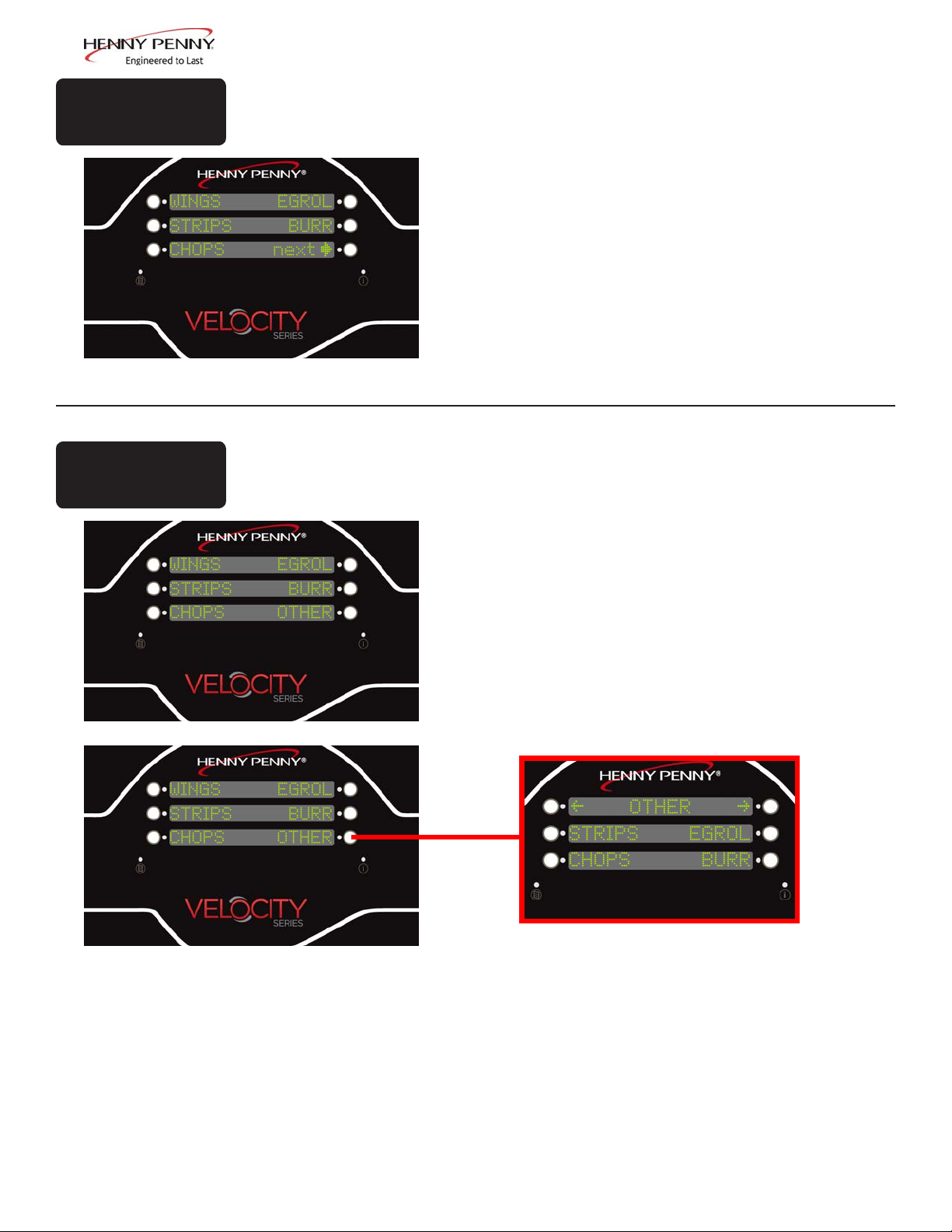
The 5+NEXT option ashows up to ve cook items, along with a
button that steps to the next cook menu.
All the cook options are displayed on the screen with the bottom-right reading “next>”. Pressing the button next to “next>”
will access the next set of cook options.
The 6 ITEM option lets the user control all six items on the cook
menu. If there is more than one cook menu, the user must program navigation links to other menus.
If there are more than 6 products that will be cooked, and this
option is selected, one of the buttons must be designated as a
link to a sub-menu, or those options will not be accessible in this
option.
See the programming section for information on setting up
menus.
March 2014
15
Page 22
3-7.
DRAIN PAN
ASSEMBLY
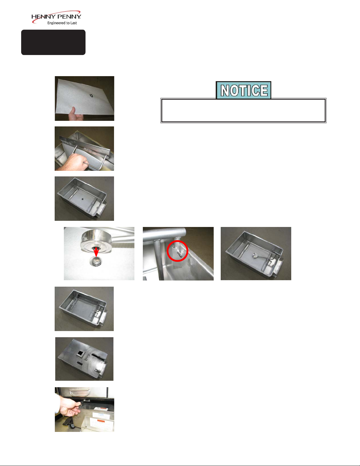
1. Slide a lter envelope onto the lter screen so the plug is protruding through the hole.
During assembly, be sure to apply oil to all O-rings to lubricate to
2. Slide the two handle clamps onto the ends of the lter screen assembly with the handles facing the same direction of the plug.
3. Place the lter screen into the bottom of the drain pan with the
plug side up.
4. Lining up the hole of the pickup tube with the plug of the lter
screen, press the tube down.
5. Position the pick up tube so that the guides slide into the notches
located on the holder in the front of the drain pan. Press down on
the pick up tube to conrm it is fully engaged on the lter screen
plug and in the holder.
help prevent tears and loss.
Dec. 2013
6. Place the crumb catcher into the drain pan so the legs straddle the
lter screen.
7. Place lid onto drain pan.
8. Push the drain pan into place and lock it into place using the locking latch.
9. To remove the drain pan for cleaning, reverse this procedure.
16
Page 23

3-8.
PRODUCT RACKING
RECOMMENDATIONS
e bottom position is to be avoided on small loads because
it is closer to the cold zone. (e oil is cooler at the bottom
of the frypot and hotter at the top.) With bigger loads,
however, there is generally enough turbulence in the oil that
the bottom rack gets sucient heat.
e top position is to be avoided on small loads because
of insucient oil coverage. With bigger loads, the top rack
has good oil coverage because the volume of product on the
lower racks raises the overall oil level.
4
3
2
1
Fully loaded with 8-head (all 4 racks used)
8-Head: Load all four racks as shown.
6-Head: Load only racks 1, 2 and 3.
4-Head: Load only racks 2 and 3.
2-Head: Load only rack 2.
March 2014
17
Page 24

3-9.
LID OPERATION
• LID MUST BE FULLY LATCHED PRIOR TO
STARTING COOK CYCLE OR PRESSURIZED
OIL AND STEAM MAY ESCAPE FRYPOT.
SEVERE BURNS WILL RESULT.
• TO AVOID SERIOUS PERSONAL INJURY, DO
NOT OPERATE WITHOUT LID COVER IN
PLACE AND ALL COMPONENTS INSTALLED.
1
To close lid:
• TO AVOID SERIOUS PERSONAL INJURY, DO
NOT TAMPER WITH ANY COMPONENT OF
LID LOCKING MECHANISM.
1. Lower the lid until lid latches into place.
2
2. Pull lid handle forward until it stops.
3
3. Lift up on the lid handle until it stops.
4
5
March 2014
4. Bring lid handle out towards you until it stops.
5. Push lid handle down, latching lid in place.
18
Page 25

3-9.
LID OPERATION
(CONT.)
DO NOT LIFT HANDLE OR FORCE LID LATCH OPEN
BEFORE THE CONTROL ALARM SOUNDS, AND IS
BLINKING “DONE” IN DISPLAY.
To open lid:
1
1. Gently raise handle until it stops.
2. Push handle back until it stops.
2
Lower the handle before attempting to raise the
lid, or damage to the lid could result.
3. Lower handle.
4. Push handle back.
3
5. Unlatch the front lid latch and raise the lid.
4
5
March 2014
If lid becomes difcult to operate, stop using the fryer and call for
service. Cables need replaced.
19
Page 26

3-10.
START-UP
If the oil is below 180o F (82o C), with the Main Power switch in
the ON position, the display will ash “START UP” “AUTO-
MELT”. The oil heats slowly to prevent scorching of the oil.
The heat cycles on and off to slowly heat the oil. When the oil
temperature reaches 215°F (102°C), Auto-Melt mode terminates
and the fryer begins heating up to the Auto-Mix temperature of
360°F (182°C).
During Start-up, the display will inform the user by displaying
a bar graph to represent the stages of the start-up process. These
stages consist of the following:
• Melt (“Mlt”)-Auto-Melt mode.
• Mix (“Mix”)-Automatic lter to ensure oil is mixed to
prevent cold pockets.
• Top Off (“Top”)- Checks to see if oil level is lled to the
proper mark. If the unit senses the oil level is low, it will run
an Auto-T op Off.
• Polish (“Pol”)-The unit will run a polish cycle.
During each stage, the bar graph will ll as each stage nears
completion. The duration of each stage depends on the
temperature of the oil at the initial start and the set-points that the
unit has in place.
Once the start-up is complete, the display will go to the main
cook menu and is ready for operations.
March 2014
20
Page 27

3-11.
FILLING THE OIL
TANK
The fresh oil tank automatically tops off the oil in the frypot
when it senses the oil level is low. User should add fresh oil to
the tank as needed. DO NOT add fresh oil directly to the frypot.
1. Pull the fresh oil tank out of the front of the fryer.
2. Open the fresh oil tank lid and locate the marks on the inside
wall of the tank.
3. Use fresh oil, ll the fresh oil tank to the marks on the inside
of the tank.
4. Shut the lid and slide back into position.
If the fresh oil tank runs low or is empty, the display will read
“FILL OIL TANK” and the left image in the middle display will
ash to represent the location of the tank on the fryer.
3-12.
CONDENSATION
TANK
This prompt will appear when the unit attempts to top off the oil
three times and is unsuccessful.
Follow the above steps to ll the tank. Once the tank is lled
press the button next to “√OK”.
Excess condensation from the pot drains into the condensation
tank. The tank is equipped with a weep hole to indicate the tank
is full and needs to be emptied.
To empty, slide the condensation tank completely out of the unit
and empty into a drain or sink.
Place back into fryer after emptying.
March 2014
21
Page 28
3-13.
FILTER PUMP
MOTOR
PROTECTOR-
MANUAL RESET
The lter pump motor is equipped with a manual reset button
located on the rear of the motor. Wait about 5 minutes before
attempting to reset this protective device to allow motor to cool.
Remove the condensation pan to reveal the reset button. It takes
some effort to reset, and a screwdriver can be used to help reset
the button.
To prevent burns caused by splashing oil, turn the unit’s
main power switch to the OFF position before resetting the
lter pump motor’s manual reset protection device.
3-14.
REGULAR
MAINTENANCE
SCHEDULE
As in all food service equipment, the Henny Penny pressure
fryer does require care and proper maintenance. The table below
provides a summary of scheduled maintenance. The following
paragraphs provide preventive maintenance procedures to be
performed by the operator.
Procedure Frequency
Changing of oil ................................... As indicated
Changing the lter envelope
Cleaning the frypot
Cleaning the Nylatrons
Lubricate Carriage Wheels.................. Annually-see Preventive Maintenance
Cleaning the deadweight assy.
Inspect Counter-Weight Cables........... Annually-see Preventive Maintenance
............................. Daily
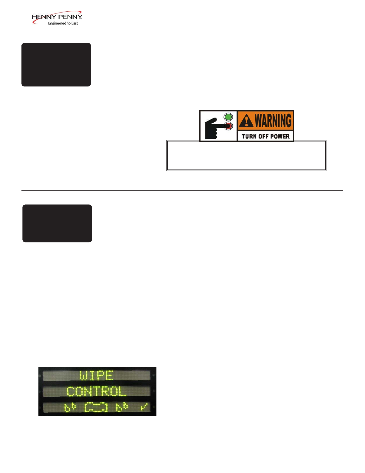
This unit is equipped with a WIPE mode. This mode gives
10 seconds to wipe the control board clean of any debris
without activating the buttons.
1. Press the (i) two times.
.............. Daily
....................... Monthly-see Preventive Maintenance
........... Monthly-see Preventive Maintenance
Aug. 2014
2. Press the button next to the √ to conrm.
3. The control board will start a count down timer for 10
seconds.
4. Once the 10 seconds expires, the control will return to
the previous screen.
22
Page 29

3-15.
INITIAL OIL FILL
The oil level must always be above the heating elements when the fryer
is heating and at the frypot level indicators on the rear of the frypot
(Figure 3-3). Failure to follow these instructions could result in a re
and/or damage to the fryer.
Before lling the pot, the oil lines need purged in order to ensure
all water or dirty oil is cleared.
1. Access the “FILTER MENU” (see section 3-19 FILTER
INSTRUCTIONS).
2. Select “6. FILL FROM OIL TANK”.
3. Push and hold the “FILL” button until fresh oil enters the
pot. Release the button.
4. Use a towel to wipe the pot clean of water and dirty oil.
5. It is recommended that a high quality frying oil be used in
the pressure fryer. Some low grade oils have a high moisture
content and cause foaming and boiling over.
Figure 3-3
To avoid severe burns when pouring hot oil
into frypot, wear gloves and take care to
avoid splashing.
6. The electric model requires 76 lbs. (34.5 kg.) of oil. The
frypot has 2 level indicator lines inscribed on the rear wall
of the frypot which show when the heated oil is at the proper
level. Figure 3-3.
7. Cold oil should be lled to the lower indicator.
BE CERTAIN THE OIL IS NEVER ABOVE THE UPPER LEVEL
INDICATOR LINE. FAILURE TO FOLLOW THESE INSTRUC-
TIONS CAN RESULT IN OIL OVERFLOWING THE FRYPOT
CAUSE SERIOUS BURNS, PERSONAL INJURY, FIRE AND/OR
PROPERTY DAMAGE.
Aug. 2014
23
Page 30

3-16.
BASIC OPERATION
Follow the procedure below on the initial start-up of the fryer,
and each time the fryer is brought from a cold, or shut down
condition, back into operation. These are basic, general
instructions.
DO NOT OVERLOAD, OR PLACE PRODUCT WITH EXTREME
MOISTURE CONTENT INTO THE RACKS. 24 LBS. (10.9 KG.) IS
THE MAXIMUM AMOUNT OF PRODUCT PER FRYPOT. FAILURE
TO FOLLOW THESE INSTRUCTIONS CAN RESULT IN OIL
OVERFLOWING THE FRYPOT WHICH COULD CAUSE SERIOUS
BURNS, PERSONAL INJURY, FIRE AND/OR PROPERTY DAMAGE.
1. Make sure the frypot is lled to the proper level with oil, to
the lower level indicator.
2. Turn the POWER switch to the ON position
3. Allow fryer to heat until set point.
The heat cycles on and off approximately 10 degrees before the
setpoint temperature, to help prevent overshooting the setpoint
Push the (i) button to see set point and true
temperature of oil
temperature. (proportional control)
4. Select product button and allow the temperature to reach set
point. Once set point has been reached, the display will read
“DROP”.
5. Before loading product onto the racks, lower racks into the
hot oil to keep the product from sticking to the racks.
March 2014
6. Slide racks of breaded product into carrier on the lid,
starting with the bottom tier, to prevent damaged product.
7. Lower and lock the lid down and press the start button.
24
Page 31

3-16.
BASIC OPERATION
8. At the end of the cycle, pressure begins venting
automatically, alarm sounds, and the display shows
“DONE”. At this time, press the “DONE” button.
(CONT.)
3-17.
CARE OF THE OIL
9. Unlock and raise the lid cautiously.
10. Use the rack handles, remove the racks of product from the
carrier, starting with the top rack.
FOLLOW THE INSTRUCTIONS BELOW TO AVOID
OIL OVERFLOWING THE FRYPOT, WHICH COULD
RESULT IN SERIOUS BURNS, PERSONAL INJURY,
FIRE, AND/OR PROPERTY DAMAGE.
1. To protect the oil when the fryer is not in immediate use,
the fryer should be put into the Cool Mode by selecting a
product menu.
2. Frying breaded products requires ltering to keep the oil
clean.
3-18.
MAIN MENU
3. The proper level of cooking oil is automatically maintained.
See Filling the Oil Tank for procedures for lling the fresh
oil tank.
4. Do not overload the racks with product (24 lbs. (10.9 kgs.)
maximum), or place product with extreme moisture content
into racks.
The Main Menu is activated by pressing and holding the
Menu button (lower left corner of the control). Once the menu
actipotes, release the button.
The Main Menu options are displayed as follows:
1. FILTER
2. INFO MODE
3. USB/DATA
4. PROGRAM
5. CLOCK SET
x. EXIT MENU
March 2014
25
Page 32

3-19.
FILTERING
INSTRUCTIONS
WITH PROLONGED USE, THE FLASHPOINT OF OIL
IS REDUCED. DISCARD OIL IF IT SHOWS SIGNS OF
EXCESSIVE SMOKING OR FOAMING. SERIOUS BURNS,
PERSONAL INJURY, FIRE, AND/OR PROPERTY DAMAGE
COULD RESULT.
e Henny Penny electric 8 head fryer the fryer automatically
performs a polish during morning startup, automatically lters aer
every cook cycle, and requires a single “Daily” maintenance lter each
day; aer lunch rush and at the end of the day.
Filter oil immediately following a Cook Cycle when the oil
temperature is in the Cool Mode.
Drain the oil at 250° F (121° C) or less. Higher temperatures cause
cracklings to burn on the steel frypot surfaces after the oil has drained.
1. Push and hold until the display reads *MAIN*.
2. Press 1 to enter the “Filter” menu. Use the buttons next to the
arrows on the display to access the next set of options.
3. Push the menu button again to cycle to next set of options.
Filter Options:
1. QUICK
2. DAILY
3. POLISH
4. DRAIN TO PAN
5. FILL FROM PAN
6. FILL FROM OIL TANK
7. DISPOSE
8. CLEAN-OUT
9. FILL FROM BULK
x. EXIT MENU
Sept. 2014
26
Page 33

3-19.
FILTERING
INSTRUCTIONS
(CONT.)
Quick Filter
Option 1 allows you to perform a quick lter of the oil. After every
cook cycle, the fryer will automatically run a quick lter. You can
choose to do one at any time by selecting this option.
1. Once you have pressed 1 for “QUICK FILTER”, a “CONFIRM”
prompt will appear on display. You can cancel by pressing the
button next to the X or conrm by pressing the button next
to the √.
2. Once you have conrmed YES, the drain will open automatically
and the oil will start to drain. The display will show arrows
pointing down indicating it is draining.
During this lter cycle, the oil will not fully drain. It
maintains a constant level during lter. The display will
show the arrows pointing up and down with a sequence
of tracing light to indicate it is still ltering.
3. After a few moments, the drain will close and the oil will return
to the pot. As it is close to being lled, the display will make
a chirp sound and a timer will start counting down on the lower
left hand side. The display will show arrows pointing up to show
it is lling.
4. In some circumstances, the fryer might not detect the oil
returning to the pot, and may ask “IS Pot FILLED?”.
5. Check the oil level to conrm all oil has returned to pot. If oil
is at the correct level mark located in pot, press “YES”. If oil
is not at the level marker, press “NO” and pump will continue
pumping.
Dec. 2013
27
Page 34

3-19.
FILTERING
INSTRUCTIONS
(CONT.)
Daily Filter
Option 2 allows you to perform a daily lter of the oil. This lter
cycle will drain the pot completely enabling the user to clean the pot.
1. Once you have pressed 2 for “DAILY FILTER”, a “CONFIRM”
prompt will appear on display. You can cancel by pressing the
button next to the X or conrm by pressing the button next
to the √.
2. Once you have conrmed YES, the drain will open
automatically and the oil will start to drain. The display will
show arrows pointing down indicating it is draining.
3. As the oil is draining, a brush symbol appears to remind you to
scrub the pot. Use a brush, scrub the walls and bottom of pot. .
4. Three prompts will appear on the display. “Fill”, “Wash”,
“Drain”.
• To wash all the crumbs down the drain, select the
“WASH”option and unit will start the wash cycle. Display
will show “WASHING”. Once completed, display will show
previous display with options.
• You can stop the wash cycle any time by pressing the button
next to “STOP”.
5. Once pot is scrubbed and washed, press “FILL” to return the oil
to the pot.
6. After a few moments, the drain will close and the oil will return
to the pot. As it is close to being lled, the display will make
a chirp sound and a timer will start counting down on the lower
left hand side. The display will show arrows pointing up to show
it is lling.
7. Once the timer has counted down, the display will prompt “IS
Pot FILLED?”
8. Check the oil level to conrm all oil has returned to pot. If oil
is at the correct level mark located in pot, press “YES”. If oil
is not at the level marker, press “NO” and pump will continue
pumping.
March 2014
28
Page 35

3-19.
FILTERING
INSTRUCTIONS
(CONT.)
Polish
Option 3 allows you to polish oil.
1. Once you have pressed 3 for “POLISH”, a “CONFIRM” prompt
will appear on display. You can cancel by pressing the button
next to the X or conrm by pressing the button next to the √.
2. Once you have conrmed YES, the drain will open automatically
and the oil will start to drain. The display will show arrows
pointing down indicating it is draining.
3. A timer will start at the bottom left corner of the display for
15:00 minutes. This will cycle the oil until the timer expires.
4. Once polish is complete, the display will indicate the oil is
returning to the pot.
5. After a moment, the display will make a chirp sound and a timer
will start.
6. Once the timer has counted down, the display will prompt “IS
Pot FILLED?”
7. Check the oil level to conrm all oil has returned to pot. If oil is
at the correct level mark located in pot, press “YES”. If oil is not
at the level marker, press “NO” and pump will continue pumping.
March 2014
29
Page 36

3-20.
BULK DISPOSE
Option 7 will access “DISPOSE”. The bulk dispose option allows the oil to be discarded to an external discard tank from the
drain pan.
Conrm controls are set to the particular set up in the location.
See Special Programming for further detail on set up.
1. Display will read “DRAIN Pot?”. Press the button next to
“√” for “YES”. The display will read “DRAINING” while to
oil drains to the drain pan.
If at any point “DRAINING” needs to be canceled, pressing the “x!” button will stop draining and give the options to
either “Fill”, “RESUME”, or “QUIT”.
“FILL” - Returns what oil has drained back to the pot.
“RESUME” - Continue draining
“QUIT” - Return the “FILTER” menu
2. Next, the display will prompt to “PURGE”. This step is to
clear the lines of any old oil.
Press and hold the “PUMP” button on the display while
watching the pot. Once clean oil starts to come out of the
jets, release the button. Allow a few moments for the old oil
to fully drain in to the pan.
3. Press the “NEXT” button once all the old oil has been
purged.
4. The display reads “DISPOSE”. Press and release the
“PUMP” button. The old oil in the drain pan will now start
to dispose.
5. Once the drain pan is empty of old oil, press the “STOP”
button to shut off the pump motor.
6. Conrm all oil is cleared from the drain pan. If further
pumping is required, press “PUMP” to continue. Then press
“STOP” when completed.
7. Press “done” and the display will read “EXIT?”. Press
“√YES” when completed.
8. If the fryer’s power switch is on, the display says “TURN
OFF UNTIL FILLED”. This display continues until the fryer
is turned off.
9. Be sure to rell the fryer with new oil before turning it on
again.
March 2014
30
Page 37

3-21.
CHANGING THE
FILTER ENVELOPE
The lter envelope should be changed daily, or whenever it becomes
clogged with crumbs.
Refer back to the Drain Pan Assembly section for instructions.
Use protective cloth or glove when disconnecting the
lter union or severe burns could result. If the lter
pan is moved while full of oil, use care to prevent
splashing, or severe burns could result.
Be sure that the lter screens, crumb catcher and
lter clips are thoroughly dry before assembly of the
lter envelope or water will dissolve the lter paper.
3-22.
CLEAN-OUT MODE
Do not use steel wool, other abrasive cleaners or cleaners/sanitizer containing chlorine,
bromine, iodine or ammonia chemicals, as these will deteriorate the stainless steel material and
shorten the life of the unit.
Do not use a water jet (pressure sprayer) to clean the unit, or component damage could result.
Do not bang brushes or scrapers on the pot band. Damage to the pot band may cause gaps
around the gasket and will not build pressure properly.
Make sure the inside of the frypot, the drain
valve opening, and all parts that come in
contact with the new oil are as dry as possible.
Sept. 2014
DO NOT CLOSE LID WITH WATER AND/
OR CLEANER IN FRYPOT. WATER UNDER
PRESSURE BECOMES SUPERHEATED. WHEN
LID IS OPENED, ESCAPING WATER AND STEAM
WILL RESULT IN SEVERE BURNS.
31
Page 38

3-22.
CLEAN-OUT MODE
(CONT.)
After the initial installation of the fryer, as well as before every
change of oil, the frypot should be thoroughly cleaned as
follows:
1. Be sure the oil is disposed properly. If the unit has bulk oil,
see Bulk Dispose (Section 3-20) for instructions.
2. Turn the POWER switch to OFF position.
Moving the fryer or lter drain pan while containing hot oil is
not recommended. Hot oil can splash out and severe burns could
result. The lter drain pan must be as far back under fryer as it
will go, and the cover in place. Be sure the hole in the cover lines
up with the drain before opening the drain. Failure to follow
these instructions causes splashing of oil and could result in
personal injury.
3. Raise lid, remove the racks and carrier from lid, and tilt lid
back, so that the lid won’t interfere with cleaning.
4. Fill the pot with warm water half way between the bottom and
the oil level indicators.
5. Add 8 to 10 ounces of fryer cleaning solution.
Always wear chemical splash goggles or face shield and protec-
tive rubber gloves when cleaning the frypot as the cleaning solu-
tion is highly alkaline. Avoid splashing or other contact of the
solution with your eyes or skin. Severe burns and possible blind-
ness will result. Carefully read the instructions on the cleaner. If
solution comes in contact with your eyes, rinse thoroughly with
cool water and see a physician immediately.
6. Fill the pot with more warm water so that the water reaches
the crumb ring on the side of the pot.
7. Depending on the preferred cleaning method, see the
appropriate section below to continue the Clean-Out mode.
Options:
• Cold-Soak Clean Out
• Heated Clean-Out
Sept. 2014
Cold-Soak Clean-Out
If unit is set to Cold-Soak mode (See SP-22 in the Special
Program section), follow the following steps.
8. If the unit is not turned off, the control will prompt “TURN
FRYER OFF.”
32
Page 39

9. With the fryer off, the display will read, “-OFF-” “(soaking)”
with “done√” in the bottom right-hand display.
3-22.
CLEAN-OUT MODE
(CONT.)
10. Use a scrub brush to periodically scrub the vat walls to loosen
any crumbs or debris.
11. Once the desired time, according to the uses discretion, has
expired, press the button next to “done√”.
12. The display will show “DONE SOAKING?” “YES” “NO”.
If not done soaking, press “NO” to return to the “OFF”
“(soaking)” screen.
If completed with the soaking process, press the button next
to “YES” to continue to the CLEAN-OUT: DRAINING THE
WATER section.
Heated Clean-Out
If unit is set to Heated Clean-Out mode (See SP-22 in the Special
Program section), follow the following steps.
8. If the unit is not turned on, the control will prompt “TURN
FRYER ON.”
9. Once the unit is powered on, “==CLEAN OUT==””heating”
along with the current temperature of the water will show in
the display. The unit starts heating to the preset temperature
(see SP-23 in the Special Program section).
At any point that Clean-Out mode needs to be canceled, press the
button next to the “x!”. This will skip the heating phase and go
straight to the CLEAN-OUT: DRAINING THE WATER section.
10. Once the temperature preset is reached, “==CLEAN
OUT==””cleaning” along with the preset time (see SP-24
in the Special Program section). The time will start to count
down.
11. When the “cleaning” phase is completed, “*DONE*” ashes
in the display then prompts to “TURN FRYER OFF”.
12. Power the unit OFF and the display shows “OFF” and the
current temperature of the water.
Allow the water time to cool before proceeding to the next steps
or burns may result.
Press the button next to “next►” to proceed to draining the water.
See CLEAN-OUT: DRAINING THE WATER section.
Sept. 2014
33
Page 40

3-22.
CLEAN-OUT MODE
(CONT.)
Clean-Out: Draining the Water
The display with read “IS CART OR PAN IN PLACE?”. A
bucket, tub or the drain pan needs to be in place under the drain
before proceeding to draining.
If using the drain pan, remove all the internal parts so the pan is
empty. DO NOT put the lid onto the pan. Must remain open for
this procedure.
When placing the drain pan under the unit, DO NOT push it all
the way back. Slide it under the unit so that it is under the drain
and can still see into the pan.
13. Once a bucket, tub or drain pan is in place, press the button
next to “YES√”.
14. The display will show “▼DRAN (hold)”. Press and hold
the illuminated button. The water will start to drain into the
bucket/tub/pan.
15. Once the level of the water is at a comfortable level, release
the button and the water will stop draining.
16. Remove the bucket/tub/pan from under the fryer and dispose.
17. Repeat the following steps until the pot is empty.
18. Once the pot is empty, press the button next to “next►”.
19. The display will ask “IS POT EMPTY?”. Conrm that all the
water is cleared from the pot. Press “√YES” if so,. Otherwise,
press “NOx” and continue the draining process.
Rinse Pot with Clean Water
20. Place the bucket/tub/pan in place under the drain.
21. The screen will read “▼OPEN DRAIN”. Press the button to
fully open the drain.
22. With the drain open, use clean water to rinse the side walls
and bottom of the pot.
Be sure not to over ll the receiving container.
Sept. 2014
23. When completed with rinsing, Press the button next to
“►◄CLOSE DRN” to close the drain.
24. Remove the container from under the fryer and dispose.
34
Page 41

3-22.
CLEAN-OUT MODE
(CONT.)
25. Repeat the following steps as needed to ensure all the cleaner
is out of the pot.
26. Once the pot is rinsed clean of all chemical water, press the
button next to “next►”.
Purge Oil Lines
This step is to clear the oil lines of any remaining water that may
be left over from cleaning or rinsing.
Conrm the Fresh Oil Tank has new oil in it.
27. The display will read “=PURGE=””►PUMP”.
28. Press and hold the button next to “►PUMP” until clean, fresh
oil comes through the jets in the bottom of the pot.
29. To clear the oil from the pot, refer back to the Rinse Pot with
Clean Water section.
30. Once pat is rinsed, press the button next to “next►”.
Wipe Pot
31. The display will read “==WIPE==””▼OPEN DRAIN”.
32. Place a bucket, tub, or drain pan under the fryer.
33. Press the button next to “▼OPEN DRAIN” to open the drain.
34. Use a clean towel to wipe the sides and bottom of the pot.
Guide all the remaining water and debris down the drain.
35. Press the button next to “►◄CLOSE DRN” to close the
drain.
36. Remove the bucket/tub/pan and discard the contents.
37. Press the button next to “next►”.
Exit Conrmation
38. The displace will read “EXIT CLEAN-OUT?”.
Sept. 2014
39. If the clean-out process is completed, press the button next to
“√YES”.
40. If the drain is open, the control will automatically close the
drain.
41. The display will read “KEEP OFF UNTIL FILLED”.
35
Page 42

3-22.
CLEAN-OUT MODE
(CONT.)
3-23.
PREVENTIVE
MAINTENANCE
42. If the power switch is in the ON position, move it to the OFF
position to power off the unit.
43. Fill the pot with fresh oil to the lower indicator.
44. Once the pot is lled with fresh oil, the fryer is ready for
normal operations.
Cleaning slides (Nylatrons) - Monthly
1. Spray Henny Penny biodegradable, food safe, foaming degreaser
(part no. 12226) on Nylatrons.
2. Raise lid up and down several times to spread the degreaser.
3. Wipe Nylatrons to remove food soil, grease, and degreaser
residue.
Lubricating Carriage Wheels - Annually
The carriage wheels, in the back of the fryer, should be lubricated at
least once a year, to allow the lid easy movement.
1. Remove the back shroud of the fryer.
2. Use spindle lube, part number 12124, place a small amount of
lube on all four (4) wheels, both top and bottom wheels. Make
sure to lube both left and right rollers.
Sept. 2014
36
Page 43

3-23.
PREVENTIVE
MAINTENANCE
(CONT.)
Cleaning DeadWeight-Monthly
DO NOT REMOVE DEADWEIGHT ASSEMBLY
WHILE FRYER IS OPERATING OR SEVERE
BURNS OR OTHER INJURIES WILL RESULT.
Allow the steam stack enough time to cool before
proceeding with the following steps.
1. Loosen the 3 thumb screws that secure the steam stack to the top of
the fryer. Do NOT fully remove the screws from the steam stack.
2. Pull the steam stack out of the fryer revealing the deadweight.
3. Use a towel to wipe any build up from the dead-weight.
4. Place the gasket onto the factory location, aligning the 3 screw
holes.
5. Place the steam stack back into place and tighten the 3 thumb
screws.
Dec. 2013
37
Page 44
3-23.
PREVENTIVE
MAINTENANCE
(CONT.)
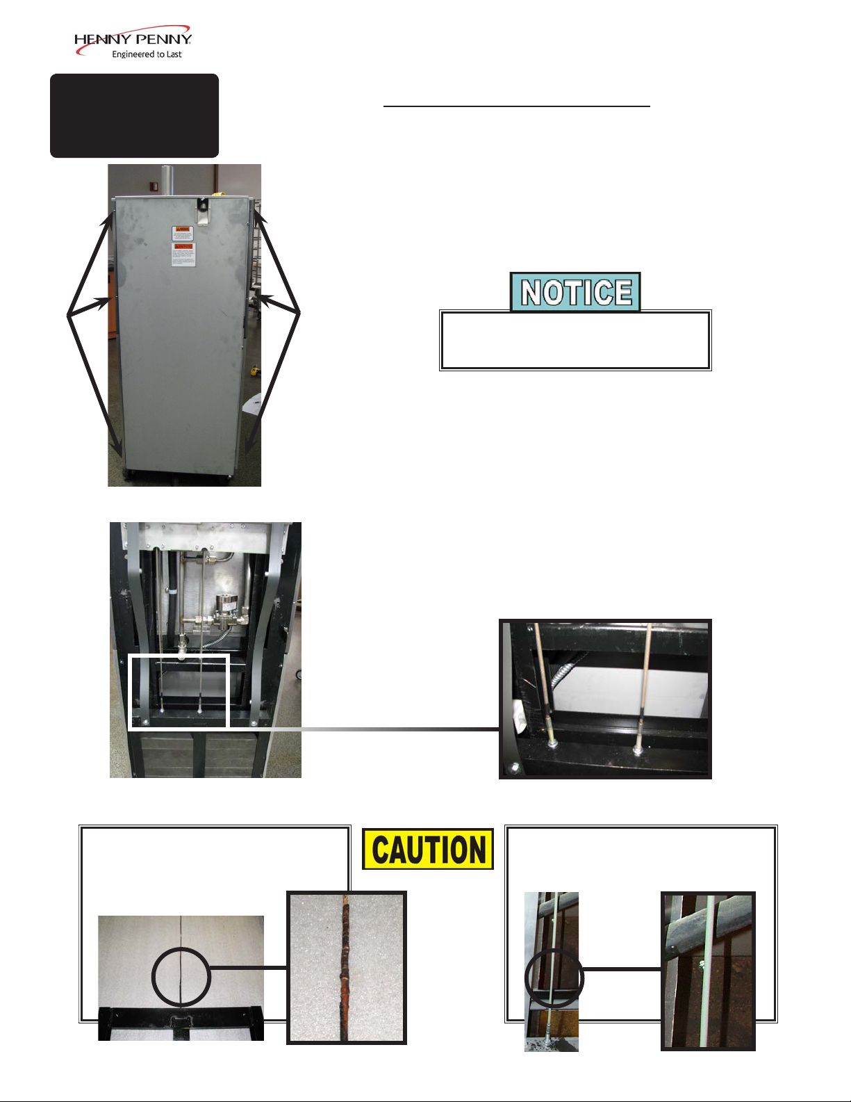
Inspect Counter-weight Cables-Annually
Henny Penny 8 head fryers use two cables in the counter-weight
mechanism that helps in the raising and lowering of the lid. Cables
should be visually inspected yearly, either as part of a planned
maintenance program or during a routine service call. Cables
more than 10 years old should be replaced regardless of inspection
results.
If lid becomes difcult to operate, stop using
the fryer and call for service. Cables need
replaced.
1. Use a 3/8” socket, remove the 6 keps nuts around exterior of
rear cover, shown in Figure 1.
2. Lift up on the rear cover and pull out at the bottom to clear
Figure 1
View of the counter-weights
with cover removed
NOT OK-REPLACE
Cracks in jacket are obvious signs
of wear
threaded studs.
3. Inspect the counter-weight cables. If cables have cracks in the
jacket, missing pieces in the jacket, or other obvious signs of
wear, call for service to have both cables replaced.
OK
No signs of wear or cracking
Dec. 2013
38
Page 45

4-1.
PROGRAM MENU
SECTION 4: PROGRAMMING
This section shows how to access the programming
(“PROG”) menu that access the products, cook and special
program.
1.PRODUCTS
2.COOK MENUS
3.SPCL PROG
4.DATA COMM
5.HEAT CTRL
6.FLTR CTRL
4-2.
PRODUCT
PROGRAMMING
1
2
3
7.TECH MODE
8.STATS MODE
9.LANGUAGE
x.EXIT MENU
1. PRODUCTS
2. COOK MENUS
3. SPECIAL PROGRAM
4. DATA COMM
5. HEAT CONTROL
This section describes how to program a new product into an
empty slot or over ride a current product.
1. Press and hold the button until *MAIN* shows in the
display.
2. Select “4. PROG”.
3. Select “1. PRODUCTS”.
4. Enter code 1,2,3 and the display will show what is the
current layout with the products.
6. FILTER CONTROL
7. TECH MODE
8. STATS MODE
9. LANGUAGE
x. EXIT MENU
5. Select an empty slot or any product that is desired to
override by pressing the button next to it. Use the buttons next to the + or - to scroll through the list of products.
6. Once the desired product or /BLANK is in the middle
display, pressing the right arrow will advance to the rst
step in programming that product.
7. Press the button next to “<-change” to proceed to changing the name. The name is what is displayed in the title
section of the display.
8. Using the buttons next to the + or - to change the letter in
the name. Once the correct letter is displayed, press the
button next the arrows to move to the next letter.
To delete any letters or numbers that may be left over
during an override or placed accidently, press the arrow
buttons unit you reach the letter or number you desire to
delete. Using the + or - buttons, advance the letters until
a blank is displayed.
March 2014
39
Page 46

4-2.
PRODUCT
PROGRAMMING
(CONT.)
9. Press the button next to the √ to conrm complete.
10. Press the right-arrow button to advance to “LINK ID”. The
Link ID is what is displayed in the cook menu. This is used as
an abbreviation or short name.
Press the button next to “<-change” to proceed with changing
the Link ID.
11. Using the buttons next to the + or - to change the letters.
Once complete, press the right-arrow button to advance to the
“COOK TIME”.
12. Using the buttons next to the left set of + or - to change the
minutes in the timer. The right set of + or - are used to change
the seconds. Once complete, press the right-arrow button to
advance to “TEMP 1”.
13. Using the buttons next to the + or - to change the numbers in
the temperature. Once complete, press the right-arrow button
to advance to “PRESSURE”.
14. Using the buttons next to the + or - to change it to either “ON”
or “OFF”. Press the right arrow to advance to the “STEP 2
AT” options.
15. “STEP 2 AT” will determine at what time the next set or
temperature and pressure settings will actipote. Use the + or
- to change the time then press the right arrow to advance to
“TEMP 2”.
16. Use the + or - to adjust the temperature then press the right arrow to advance to “PRESSURE 2” to wither “ON” or “OFF”.
17. Using the + or - buttons to select either “ON “ or “OFF”. Re-
peat these steps until complete cook cycle is set. One the nal
pressure is set, advance to the next step.
18. Once complete, enter 0:00 in the time and this will automatically be the end of the cook cycle.
March 2014
40
Page 47

4-3.
SPECIAL
PROGRAMMING
This section shows how to access the Special Program area of
the controls in order to program cook menus, clock, and other
features.
1. Push and hold until the display reads *MAIN*.
2. Enter the code: 1, 2, 3
3. Press the again to access the next set of options.
4. Press 4 to enter the “PROG” menu. Use the buttons next to
the arrows on the display to access the next set of options.
Special Programming consist of the following:
5. Use the left or right arrows to navigate through the options.
SP-1 • TEMP UNITS
SP-2 • LANGUAGE
SP-3 • SYSTEM INIT
SP-4 • RADIO SYSTEM ENABLED?
SP-5 • AUDIO VOL (Loudness)
SP-6 • AUDIO TONE (Frequency)
SP-7 • MELT CYCLE
SP-8 • START-UP POLISH ENABLED?
SP-9 • START-UP GO WHERE?
SP-10 • COOK MENUS OPTION
SP-11 • COOK MENU BUTTONS
SP-12 • COOK DONE GO WHERE?
SP-13 • AUTO-MENU MINUTES
SP-14 • AUTO-MENU GO WHERE?
SP-15 • COOL TEMP
SP-16 • PROD PROG T1>T2>T3)?
SP-17 • BULK DISPOSE?
SP-18 • BULK SUPPLY?
SP-19 • COOKING: SHOW PSI?
SP-20 • CHANGE MGR CODE
SP-21 • CHANGE USAGE CODE
SP-22 • CLEAN-OUT TYPE
SP-23 • CLEAN-OUT TEMP
SP-24 • CLEAN-OUT MINUTES
SP-1 • TEMPERATURE DISPLAY UNITS
1. Use the + or - to change between Fahrenheit (F°) or Celsius
(C°).
SP-2 • OPERATION LANGUAGE
1. Use the + or - buttons to scroll through the list of languages.
SP-3 • SYSTEM INITIALIZE
Sept. 2014
1. Press and hold the button next to “hold->” for three seconds.
2. System will re-initialize back to default settings.
SP-5 • AUDIO VOLUME (Loudness)
1. Use the + or - buttons will adjust the volume of the speaker
between 0-10.
2. Press the button next to “test” on the display.
41
Page 48

4-3.
SPECIAL
PROGRAMMING
(CONT.)
SP-6 • AUDIO TONE (Frequency)
1. Press the + or - to adjust the frequency setting,
2. Press the button next to “test” on the display.
SP-7 • MELT CYCLE
Specify the desired Melt Mode heating cycle.
1. Use the + or - to select wither “Solid” or “Liquid”.
SP-8 • START-UP POLISH ENABLED?
Specify whether or not an automatic polish operation should be
performed as part of the normal, morning startup process.
1. Use the + or - to select either “YES” or “NO”.
SP-9 • START-UP GO WHERE?
Specify where the control should go after exiting Melt. Choices
are “STAY PROD”, “PREV MENU”, or go specically to any of
the ten Cook Menus.
1. Use + or - to navigate through options.
SP-10 • COOK MENUS (Cook Menu Conguration)
1. Use the + or - buttons to navigate through cook menu
options.
• “4+TITLE”
• “5+NEXT”
• “6 ITEMS”
See MENU OPTIONS for descriptions and examples.
SP-17 • BULK DISPOSE?
1. Use the + or - buttons to navigate through the three options:
• “NONE”
• “FRONT”
• “REAR”
2. “NONE”- Oil dispose is by draining into a disposal cart or
shuttle.
Sept. 2014
3. “FRONT”- Dispose by pumping through the front hose
connection by press and holding the illuminated button.
4. “REAR”- Dispose by pumping through the rear plumbing
connection.
42
Page 49

4-3.
SPECIAL
PROGRAMMING
(CONT.)
SP-18 • BULK OIL SUPPLY?
1. Use the + or - buttons to select either “YES” or “NO” for
whether or not a bulk oil supply is available for relling the
ATO oil tank and vat with fresh oil.
SP-22 • CLEAN-OUT TYPE
This section list the two options for Clean Out Modes
• Cold-Soak
• Heater
1. Use te + or - to change the options.
SP-23 • CLEAN-OUT TEMP
NOT AVAILABLE FOR COLD-SOAK OPTION
Set the desired temperature for the water during Clean Out Mode.
1. Use the + or - to change the temperature.
SP-24 • CLEAN-OUT MINUTES
NOT AVAILABLE FOR COLD-SOAK OPTION
Set the desired time for the Clean-Out Mode.
1. Use the + or - to change the minutes.
Sept. 2014
43
Page 50

4-4.
FILTER CONTROL
Filter Control Mode allows the parameters during a lter cycle to
be modied for the best results depending on the oil type being
used.
Each parameter are grouped into sections that control a particular
settings. The section are grouped as follows. See the next page
for the full list of Filter Control programs.
• Quick Filter Settings
• Daily Filter Settings
• Polish Settings
• Auto-Top Off Settings
• Start-Up Mode Settings
• Cook Mode Auto Mix Settings
• Miscellaneous Settings
To access Filter Control:
1. Press and hold the button until *MAIN* shows in the
display.
2. Select “4. PROG”.
3. Select “6. FLTR CTRL”.
4. Enter code 1,2,3.
5. Use the left or right arrows to navigate through the options.
March 2014
44
Page 51

4-4.
FILTER CONTROL
(CONT.)
Quick Filter Settings
FC-1 “QUICK FILTER: AFTER ‘X’ COOKS”
FC-2 “QUICK FILTER: DROP OIL: TIME”
FC-3 “QUICK FILTER: DROP OIL: DRAIN OPENING”
FC-4 “QUICK FILTER: FILTER: TIME”
FC-5 “QUICK FILTER: FILTER: DRAIN OPENING”
FC-6 “QUICK FILTER: FILL: DETECT AT LEVEL PROBE, KEEP PUMPING”
FC-7 “QUICK FILTER: NORMAL FILL TIME”
FC-8 “QUICK FILTER: FILL: NO DETECT: MAX PUMP”
Daily Filter Settings
FC-9 “DAILY FILTER: DROP OIL TIME”
FC-10 “DAILY FILTER + POLISH: FILL: DETECT AT LEVEL PROBE, KEEP PUMPING”
FC-11 “DAILY FILTER: FILL: NO DETECT: MAX PUMP”
Polish Settings
FC-12 “POLISH: DROP OIL: TIME”
FC-13 “POLISH: DROP OIL: DRAIN OPENING”
FC-14 “POLISH: FILTER: TIME”
FC-15 “POLISH: FILTER: DRAIN OPENING”
FC-16 “POLISH: NORMAL FILL TIME”
FC-17 “POLISH: FILL: NO DETECT: MAX PUMP”
Auto-Top Off Settings
FC-18 “AUTO-TOPOFF: ENABLED?”
FC-19 “AUTO-TOPOFF: PUMP TIME”
FC-20 “AUTO-TOPOFF: REPEAT”
FC-21 “AUTO-TOPOFF: AFTER X ATTEMPTS, CHECK A TO”
FC-22 “COOK MODE - FORCED ATO CHECK AFTER ‘X’ COOKS”
Start-Up Mode Settings
FC-23 “START-UP: NEEDED IF TEMP < X”
FC-24 “START-UP MIX: ENABLED?”
FC-25 “START-UP MIX: PRE-HEAT MAX TEMP”
FC-26 “START-UP MIX: DROP OIL: TIME”
FC-27 “START-UP MIX: FILTER: TIME”
FC-28 “START-UP MIX: NORMAL FILL TIME”
FC-29 “START-UP MIX: FILL: NO DETECT: MAX PUMP”
FC-30 “START-UP ATO CHECK: ENABLED?”
FC-31 “START-UP ATO CHECK: PRE-HEAT MAX TEMP”
FC-32 “START-UP POLISH: ENABLED?”
FC-33 “START-UP POLISH: PRE-HEAT MAX TEMP”
Cook Mode Auto Mix Settings
FC-34 “COOK MODE AUTO-MIX: ENABLED?”
FC-35 “COOK MODE AUTO-MIX: DROP OIL: TIME”
FC-36 “COOK MODE AUTO-MIX: FILTER: TIME”
FC-37 “COOK MODE AUTO-MIX: NORMAL FILL TIME”
FC-38 “COOK MODE AUTO-MIX: FILL: NO DETECT: MAX PUMP”
FC-39 “COOK MODE AUTO-MIX: DESIRED BOTTOM TEMP”
FC-40 “COOK MODE AUTO-MIX: MIN REQUIRED OIL TEMP”
FC-41 “COOK MODE AUTO-MIX: MIN REPEAT”
FC-42 “COOK MODE TIMED AUTO-MIX, IF BAD BOTTOM PROBE”
Dispose Settings
FC-43 “DISPOSE: DROP OIL: DRAIN OPENING”
March 2014
Miscellaneous Settings
FC-44 “ALWAYS ASK ‘IS POT FILLED?’”
FC-45 “ANY FILL: NOT FILLED, EXTRA PUMP TIME”
45
Page 52

4-4.
FILTER CONTROL
(CONT.)
Quick Filter Settings
These parameters control the Quick Filter operation, which
activates automatically after a cook cycle, and may also be
initiated manually from the Filter Menu.
The Quick Filter has three basic steps:
1. DROP: Opens the drain and drops the oil level by a certain
amount. Depending on settings, could drop the oil level just a
few inches during this phase, or could drain the entire pot.
2. FILTER: Runs the lter pump with the drain partially open
for a given time, pumping the oil through the lter paper
to clean the oil. This operation typically holds a relatively
constant oil level in the pot.
3. FILL: Closes the drain fully and runs the lter pump to
rell the pot. Watches for a temperature rise on the upper
temperature probe (level probe) to indicate that the pot has
relled. Runs the pump a bit longer to get the last of the oil
out of the lter pan, then turns the pump off.
The Start-up Mix and the Cook Mode Auto-Mix operations are
specialized versions of the Quick Filter, and share some of the
Quick Filter programmable parameters. For example, both of the
Mix operations use the Quick Filter’s “Max Pump Time” setting.
FC-1 “QUICK FILTER: AFTER ‘X’ COOKS”
Controls automatic activation of the Quick Filter after the
specied number of cook cycles.
1. Enter a new value by using the product numbers.
2. Press the button next to √ to accept the new value.
3. Press the button next to X to return to default or previous
setting.
March 2014
46
Page 53

4-4.
FILTER CONTROL
(CONT.)
FC-2 “QUICK FILTER: DROP OIL: TIME”
FC-3 “QUICK FILTER: DROP OIL: DRAIN
OPENING”
For the “Drop” phase: how long to spend dropping the oil level,
and how far to open the drain valve during this step.
1. Enter a new value by using the product numbers.
2. Press the button next to √ to accept the new value.
3. Press the button next to X to return to default or previous
setting.
For very thin (low viscosity) cooking oils, drain opening setting
may need to reduce from the default value.
FC-4 QUICK FILTER: FILTER TIME
FC-5 QUICK FILTER: FILTER DRAIN POSITION
At the end of“Drop” (drop oil level) phase, the drain closes
down to a partially open position and the lter pump runs for the
specied “Filter Time”.
1. Enter a new value by using the product numbers.
2. Press the button next to √ to accept the new value.
3. Press the button next to X to return to default or previous
setting.
For very thin (low viscosity) cooking oils, you might need to
reduce the drain opening setting from the default value.
FC-6 QUICK FILTER: FILL--DETECT AT LEVEL
PROBE, KEEP PUMPING
When relling the pot, species how long to keep pumping after
the oil initially reaches or splashes on the upper probe and the
expected temperature rise is observed.
1. Enter a new value by using the product numbers.
2. Press the button next to √ to accept the new value.
March 2014
3. Press the button next to X to return to default or previous
setting.
47
Page 54

4-4.
FILTER CONTROL
(CONT.)
FC-7 QUICK FILTER: FILL--NO DETECT: MAX
PUMP
The expected time it takes to rell the vat at the end of a Quick
Filter.
1. Enter a new value by using the product numbers.
2. Press the button next to √ to accept the new value.
3. Press the button next to X to return to default or previous
setting.
FC-8 “QUICK FILTER: FILL: NO DETECT: MAX
PUMP”
If the fryer pumps for this amount of time during the Fill phase
without observing a temperature rise on the upper temperature
probe, the control turns the pump off, and asks “IS POT
FILLED?”.
1. Enter a new value by using the product numbers.
2. Press the button next to √ to accept the new value.
3. Press the button next to X to return to default or previous
setting.
For 50 Hz systems, or if the control routinely gives up before the
pot is relled, you might need to increase the “max pump” time
from the default value. 50 Hz pumps may run more slowly than
60 Hz pumps.
Daily Filter Settings
FC-9 “DAILY FILTER: DROP OIL: TIME”
Controls the time duration of the initial draining of the pot.
1. Enter a new value by using the product numbers.
2. Press the button next to √ to accept the new value.
3. Press the button next to X to return to default or previous
setting.
March 2014
48
Page 55

4-4.
FILTER CONTROL
(CONT.)
FC-10 “DAILY FILTER + POLISH: FILL: DETECT
AT LEVEL PROBE, KEEP PUMPING”
When relling the pot, species how long to keep pumping after
the oil reaches the upper probe and the expected temperature rise
is observed.
1. Enter a new value by using the product numbers.
2. Press the button next to √ to accept the new value.
3. Press the button next to X to return to default or previous
setting.
In a Daily Filter, a Fill operation can be stopped by the user at
any time.
FC-11 “DAILY FILTER: FILL: NO DETECT: MAX
PUMP”
If the fryer pumps for this amount of time during the Fill phase
without observing a temperature rise on the upper temperature
probe, the control turns the pump off, and asks “IS POT
FILLED?”. If pot is not lled completely, press “NO” and the
pump will attempt to ll further.
1. Enter a new value by using the product numbers.
2. Press the button next to √ to accept the new value.
3. Press the button next to X to return to default or previous
setting.
For 50 Hz systems, or if the control routinely gives up before the
pot is relled, you might need to increase the “max pump” time
from the default value. 50 Hz pumps run more slowly than 60 Hz
pumps.
March 2014
49
Page 56

Polish Settings
4-4.
FILTER CONTROL
(CONT.)
FC-12 “POLISH: DROP OIL: TIME”
FC-13 “POLISH: DROP OIL: DRAIN OPENING”
For the “Drop” phase: how long to spend dropping the oil level,
and how far to open the drain valve during this step.
1. Enter a new value by using the product numbers.
2. Press the button next to √ to accept the new value.
3. Press the button next to X to return to default or previous
setting.
For very thin (low viscosity) cooking oils, you might need to
reduce the drain opening setting from the default value.
FC-14 “POLISH: FILTER: TIME”
FC-15 “POLISH: FILTER: DRAIN OPENING”
At the end of the “Drop” (drop oil level) phase, the drain closes
down to a partially open position and the lter pump runs for the
specied “Filter Time”.
1. Enter a new value by using the product numbers.
2. Press the button next to √ to accept the new value.
3. Press the button next to X to return to default or previous
setting.
For very thin (low viscosity) cooking oils, you might need to
reduce the drain opening setting from the default value.
FC-16 “POLISH: NORMAL FILL TIME”
The expected time it takes to rell the vat at the end of a Polish
operation. When relling the vat, if the fryer pumps for one and
a half times this expected time, the “Slow Filling” warning is
activated, alerting that the fryer is pumping more slowly than
expected.
1. Enter a new value by using the product numbers.
2. Press the button next to √ to accept the new value.
March 2014
3. Press the button next to X to return to default or previous
setting.
50
Page 57

4-4.
FILTER CONTROL
(CONT.)
FC-17 “POLISH: FILL: NO DETECT: MAX PUMP”
If the fryer pumps for this amount of time during the Fill phase
without observing a temperature rise on the upper temperature
probe, the control turns the pump off, and asks “IS POT
FILLED?”. If pot is not lled completely, press “NO” and the
pump will attempt to ll further.
1. Enter a new value by using the product numbers.
2. Press the button next to √ to accept the new value.
3. Press the button next to X to return to default or previous
setting.
For 50 Hz systems, or if the control routinely gives up before the
pot is relled, you might need to increase the “max pump” time
from the default value. 50 Hz pumps run more slowly than 60 Hz
pumps.
Auto-Top Off Settings
FC-18 “AUTO-TOPOFF: ENABLED?”
Enables or disables all Auto-Topoff (ATO) operations.
1. Press the + or - to select either “YES” or “NO”.
Disabling the Auto-Topoff feature would normally be done only
if the topoff system itself has failed, in order to avoid the “Fill
Oil Tank” messages that occur if the fryer doesn’t detect oil at
the proper level after 3 attempts.
FC-19 “AUTO-TOPOFF: PUMP TIME”
Species how long the ATO pump runs for each individual ATO
pulse.
1. Enter a new value by using the product numbers.
2. Press the button next to √ to accept the new value.
3. Press the button next to X to return to default or previous
setting.
This setting may be manually adjusted as needed. Ideally, each
ATO pulse pumps about 1/8” to 3/16” (5 mm) of fresh oil into
the pot.
March 2014
51
Page 58

4-4.
FILTER CONTROL
(CONT.)
FC-20 “AUTO-TOPOFF: REPEAT”
Species how long the control waits before assessing the oil
level and generating a second ATO pulse if the oil level is still
low.
1. Enter a new value by using the product numbers.
2. Press the button next to √ to accept the new value.
3. Press the button next to X to return to default or previous
setting.
FC-21 “AUTO-TOPOFF: AFTER X A TTEMPTS,
CHECK A TO”
After each ATO pulse, the control monitors the level probe
temperature to see if the oil has been brought up to the proper
level. If not, a second ATO pulse is given. After a certain number
of pulses, as specied by this setting, if the oil level still has
not been brought up to the proper level, the control beeps and
displays “FILL OIL TANK”.
1. Enter a new value by using the product numbers.
2. Press the button next to √ to accept the new value.
3. Press the button next to X to return to default or previous
setting.
If “X” pulses of oil haven’t brought the level up, the control
assumes that the oil tank is empty -- that no oil is being pumped
into the pot -- and displays the “Fill Oil Tank” message.
If the fryer is congured to use a Bulk Oil Supply system, the
message displayed is “CHECK BULK OIL SUPPLY” rather
than “FILL OIL TANK”. In this case, it is possible that the
remote bulk supply tank is empty, that the bulk supply plumbing
connection is not connected to the fryer, or that the bulk supply
electrical connection is not connected.
FC-22 “COOK MODE - FORCED ATO CHECK
AFTER ‘X’ COOKS”
1. Enter a new value by using the product numbers.
March 2014
2. Press the button next to √ to accept the new value.
3. Press the button next to X to return to default or previous
setting.
52
Page 59

Start-Up Mode Settings
4-4.
FILTER CONTROL
(CONT.)
FC-23 “START-UP: NEEDED IF TEMP < X”
If the oil temperature is below 215°F when the fryer is turned
on, the fryer always executes a Melt Mode -- regardless of this
“Start-up Needed” setting. Melt Mode is important in assuring
gentle heating of the oil when it is thick and perhaps not yet
owing well.
1. Enter a new value by using the product numbers.
2. Press the button next to √ to accept the new value.
3. Press the button next to X to return to default or previous
setting.
FC-24 “START-UP MIX: ENABLED?”
Phase 2 of the morning startup procedure is to execute the Start-
up Mix operation: drop all of the oil into the drain pan, lter it
for a short time, and pump it back into the vat. This feature is
important in thermally mixing the oil to eliminate cold spots and
eliminate the milky oil in the bottom of the pot.
This setting controls whether or not the Mix operation is
performed automatically as part of morning start-up. It is
recommended that the Start-up Mix feature is always enabled.
1. Press the + or - to select either “YES” or “NO”.
FC-25 “START-UP MIX: PRE-HEAT MAX TEMP”
The Start-Up Mix procedure consists of two steps:
• Heat up the oil to the Mix Preheat temperature.
• Drop the oil, lter, and rell the pot.
1. Enter a new value by using the product numbers.
2. Press the button next to √ to accept the new value.
3. Press the button next to X to return to default or previous
setting.
March 2014
53
Page 60

4-4.
FILTER CONTROL
(CONT.)
FC-26 “START-UP MIX: DROP OIL: TIME”
This setting species how long the oil should drain during the
“Drop” phase of the Start-up Mix.
1. Enter a new value by using the product numbers.
2. Press the button next to √ to accept the new value.
3. Press the button next to X to return to default or previous
setting.
FC-27 “START-UP MIX: FILTER: TIME”
This setting species how long the oil should circulated during
the “Filter” phase of the Start-up Mix,
1. Enter a new value by using the product numbers.
2. Press the button next to √ to accept the new value.
3. Press the button next to X to return to default or previous
setting.
FC-28 “START-UP MIX: NORMAL FILL TIME”
The expected time it takes to rell the vat at the end of a Start-up
Mix operation.
1. Enter a new value by using the product numbers.
2. Press the button next to √ to accept the new value.
3. Press the button next to X to return to default or previous
setting.
FC-29 “START-UP MIX: FILL: NO DETECT: MAX
PUMP”
If the fryer pumps for this amount of time during the Fill phase
without observing a temperature rise on the upper temperature
probe, the control turns the pump off, and asks “IS POT
FILLED?”. If pot is not lled completely, press “NO” and the
pump will attempt to ll further.
1. Enter a new value by using the product numbers.
2. Press the button next to √ to accept the new value.
March 2014
3. Press the button next to X to return to default or previous
setting.
54
Page 61

4-4.
FILTER CONTROL
(CONT.)
FC-30 “START-UP ATO CHECK: ENABLED?”
Species whether or not the ATO (auto-topoff) Check -- the third
step of the Start-up Mode -- is enabled.
1. Press the + or - to select either “YES” or “NO”.
FC-31 “START-UP ATO CHECK: PRE-HEAT MAX
TEMP”
The Start-Up Auto-Polish procedure consists of two steps:
• Heat up the oil to the Polish Preheat temperature.
• Drop the oil, lter (for a long time), and rell the pot.
1. Enter a new value by using the product numbers.
2. Press the button next to √ to accept the new value.
3. Press the button next to X to return to default or previous
setting.
FC-32 “START-UP POLISH: ENABLED?”
Phase 4 of the morning startup procedure is to execute the Start-
up Auto-Polish: drop the oil into the drain pan, lter it for a long
time, and pump it back into the pot. This feature is important in
cleaning the oil and restoring clarity to it. Filter powder should
be added to the drain pan in order for the Polish operation to be
most effective.
1. Press the + or - to select either “YES” or “NO”.
FC-33 “START-UP POLISH: PRE-HEAT MAX
TEMP”
The Start-Up Auto-Polish procedure consists of two steps:
• Heat up the oil to the Polish Preheat temperature.
• Drop the oil, lter (for a long time), and rell the pot.
1. Enter a new value by using the product numbers.
2. Press the button next to √ to accept the new value.
3. Press the button next to X to return to default or previous
setting.
March 2014
55
Page 62

4-4.
FILTER CONTROL
(CONT.)
Cook Mode Auto Mix Settings
FC-34 “COOK MODE AUTO-MIX: ENABLED?”
This setting determines whether or not the Cook Mode Auto-Mix
feature is enabled.
1. Press the + or - to select either “YES” or “NO”.
FC-35 “COOK MODE AUTO-MIX: DROP OIL:
TIME”
This setting species how long the oil should drain during the
“Drop Oil” phase of the Cook Mode Auto-Mix.
1. Enter a new value by using the product numbers.
2. Press the button next to √ to accept the new value.
3. Press the button next to X to return to default or previous
setting.
FC-36 “COOK MODE AUTO-MIX: FILTER: TIME”
The Cook Mode Auto-Mix is a modied Quick Filter operation.
It consists of three phases: Drop (drop the oil level), Filter
(circulate it through the lter paper), and Fill (pump the oil back
into the pot).
1. Enter a new value by using the product numbers.
2. Press the button next to √ to accept the new value.
3. Press the button next to X to return to default or previous
setting.
FC-37 “COOK MODE AUTO-MIX: NORMAL FILL
TIME”
The expected time it takes to rell the vat at the end of an auto-
mix operation.
1. Enter a new value by using the product numbers.
2. Press the button next to √ to accept the new value.
3. Press the button next to X to return to default or previous
setting.
March 2014
56
Page 63

4-4.
FILTER CONTROL
(CONT.)
FC-38 “COOK MODE AUTO-MIX: FILL: NO
DETECT: MAX PUMP”
If the fryer pumps for this amount of time during the Fill phase
without observing a temperature rise on the upper temperature
probe, the control turns the pump off, and asks “IS POT
FILLED?”. If pot is not lled completely, press “NO” and the
pump will attempt to ll further.
1. Enter a new value by using the product numbers.
2. Press the button next to √ to accept the new value.
3. Press the button next to X to return to default or previous
setting.
FC-39 “COOK MODE AUTO-MIX: DESIRED
BOTTOM TEMP”
The purpose of the Cook Mode Auto-Mix operation is to attempt
to keep the bottom of the pot hot enough that crumbs don’t stick.
1. Enter a new value by using the product numbers.
2. Press the button next to √ to accept the new value.
3. Press the button next to X to return to default or previous
setting.
FC-40 “COOK MODE AUTO-MIX: MIN REQUIRED
OIL TEMP”
This is the minimum oil temperature required in order to activate
an Auto-Mix operation.
1. Enter a new value by using the product numbers.
2. Press the button next to √ to accept the new value.
3. Press the button next to X to return to default or previous
setting.
FC-41 “COOK MODE AUTO-MIX: MIN REPEAT”
This setting controls how often a bottom-temperature triggered
Auto-Mix can repeat.
March 2014
1. Enter a new value by using the product numbers.
2. Press the button next to √ to accept the new value.
3. Press the button next to X to return to default or previous
setting.
57
Page 64

4-4.
FILTER CONTROL
(CONT.)
FC-42 “COOK MODE TIMED AUTO-MIX, IF BAD
BOTTOM PROBE”
This option is used only if the temperature probe on the bottom
of the pot has failed or is disconnected.
1. Enter a new value by using the product numbers.
2. Press the button next to √ to accept the new value.
3. Press the button next to X to return to default or previous
setting.
Dispose Settings
FC-43 “DISPOSE: DROP OIL: DRAIN OPENING”
This setting species the drain opening to be used when draining
the oil to a disposal cart, shuttle, or bucket for disposal. (Does
not apply to Bulk Dispose operations.)
1. Enter a new value by using the product numbers.
2. Press the button next to √ to accept the new value.
3. Press the button next to X to return to default or previous
setting.
Miscellaneous Settings
FC-44 “ALWAYS ASK ‘IS POT FILLED?’ ”
This option can be engaged to always ask -- at the end of each
Quick Filter, Auto-Mix, and Polish operation -- if the pot is
lled. Normally, the control asks “Is Pot Filled?” only if it
has pumped for a long time attempting to ll the pot, but no
temperature rise was observed on the upper temperature probe.
1. Press the + or - to select either “YES” or “NO”.
FC-45 “ANY FILL: NOT FILLED, EXTRA PUMP
TIME”
When relling the pot at the end of a Quick Filter, Auto-Mix,
or Polish operation, the control closes the drain and runs the
pump until a suitable temperature rise is observed on the upper
temperature probe (the level probe). If no temperature rise is
seen after pumping for a reasonable maximum pumping time,
the control stops, turns the pump off, and asks “Is Pot Filled?”.
March 2014
1. Enter a new value by using the product numbers.
2. Press the button next to √ to accept the new value.
3. Press the button next to X to return to default or previous
setting.
58
Page 65

SECTION 5: TROUBLESHOOTING
5-1.
TROUBLESHOOTING
GUIDE
PROBLEM CAUSE CORRECTION
Power switch on but fryer
completely inoperative
Pressure not exhausting at
end of Cook Cycle
• Open circuit • Fryer plugged in
• Check breaker or fuse at wall
• Solenoid or exhaust line clogged • Turn off and allow fryer to cool
to release the pressure in frypot;
have all lines, solenoid and
exhaust tank cleaned
Relief valve vents
Pressure does not build
Oil not heating
Foaming or boiling over
Oil not draining
• Operating pressure too high
• Deadweight clogged
• Not enough product in frypot
• Metal shipping spacer not removed
from deadweight assy.
• Pressure not programmed
• Lid gasket leaking
• Drain valve open
• High temperature limit tripped
• See Boil-Over chart on fryer and
beginning of Operation Section in
this manual
• Drain valve clogged • Push cleaning rod through open
• Turn off and allow fryer to cool
to release the pressure in frypot;
clean deadweight; see Preventive
Maintenance Section
• Place full capacity product in
frypot when Use fresh oil.
• Remove shipping spacer; see
Unpacking Instructions Section
• Check programming
• Reverse or replace lid gasket
• Close drain valve.
• Reset high temperature limit; see
Operating Components Section
• Follow Boil-Over procedures from
chart
drain valve
Filter motor won’t run
More detailed troubleshooting information is available in the Technical Manual, available at www.
Dec. 2013
• Motor overheated • Reset motor; see Filter Pump
Motor Protector-Manual Reset
Section
hennypenny.com, or 1-800-417-8405 or 1-937-456-8405.
59
Page 66

5-2.
ERROR CODES
DISPLAY CAUSE CORRECTION
“E-4”
“CPU TOO HOT”
“E-5”
“OIL TOO HOT”
In the event of a control system failure, the digital display will show an “Error
Message”. These messages are coded: “E04”, “E05”, “E06”, “E41”. A constant
tone is heard when an error code is displayed, and to silence this tone, press any of
the product buttons.
Turn switch to OFF position, then turn switch
back to ON; if display still shows “E04”, the
Control board overheating
board is getting too hot; check for signs of
overheating behind the control panel; once
panel cools down the controls should return to
normal; if “E04” persists, replace the control
Turn switch to OFF position, then back to
ON; if display shows “E05”, the heating
Oil overheating
circuits and temperature probe should be
checked; once the unit cools down, the
controls should return to normal; if “E05”
persists, replace the control.
“E-6A”
“MAIN TEMP
PROBE FAILED”
(Open Circuit)
“E-6B”
“MAIN TEMP
PROBE FAILED”
(Shorted)
“E-10”
Temperature probe failure
High limit tripped (Software
prior to version 1.60)
Turn switch to OFF position, then back
to ON; if the display shows “E06”, the
temperature probe should be checked; once
the temperature probe is repaired, or replaced,
the controls should return to normal; if “E06”
persists, replace the control.
Check the error log to nd out the fry pot
temperature at the time the high limit tripped.
If this temperature was very low, this could
be a sign that the fry pot was turned on with
low or no oil. If this was the case, ll the pot
with oil and reset the high limit. If the trip
temperature was several degrees above the
oil set point temperature, test for a sticking
contactor and replace if faulty. If the high
limit tripped at an oil temperature, inspect the
high limit thermocouples for carbon build up
and clean if necessary. If no carbon found,
see high limit troubleshooting.
Nov. 2016
60
Page 67

DISPLAY CAUSE CORRECTION
Check the error log to nd out the fry pot
temperature at the time the high limit tripped.
If this was several degrees above the oil set
“E-10A”
“HIGH LIMIT
TRIPPED”
“E-10B”
“HIGH LIMIT
TRIPPED”
High limit tripped while vat
main probe temperature was at
or above 300°F.
High limit tripped while vat
main probe temperature was
below 300°F.
point temperature, test for a sticking contactor
and replace if faulty. If the trip temperature
was near the oil set point temperature, inspect
the high limit thermocouples for carbon build
up and clean if necessary. If no carbon found,
see high limit troubleshooting.
Check the error log to nd out the fry pot
temperature at the time the high limit tripped.
If this temperature was very low, this could
be a sign that the fry pot was turned on with
low or no oil. If this was the case, ll the pot
with oil and reset the high limit. If the high
limit tripped at a higher temperature, inspect
the high limit thermocouples for carbon build
up and clean if necessary. If no carbon found,
see high limit troubleshooting.
“E-10C”
“HIGH LIMIT
TRIPPED”
“E-10D”
“HIGH LIMIT
TRIPPED”
High limit tripped while actually
cooking (Not simply in cook
mode, but actually with cook
cycle running).
High limit tripped less than 5
minutes after fryer was
performing an AutoFilter or
Quick Filter and the control
returned to cook mode on its
own after detecting that the oil
was pumped up (based on
temperature rise on level probe).
Check the error log to nd out the fry pot
temperature at the time the high limit tripped.
If this was several degrees above the oil set
point temperature, test for a sticking contactor
and replace if faulty. If the trip temperature
was near the oil set point temperature, inspect
the high limit thermocouples for carbon build
up and clean if necessary. If no carbon found,
see high limit troubleshooting.
Check the error log to nd out the fry pot
temperature at the time the high limit tripped.
If this was several degrees above the oil set
point temperature, test for a sticking contactor
and replace if faulty. If the trip temperature
was near the oil set point temperature, inspect
the high limit thermocouples for carbon build
up and clean if necessary. If no carbon found,
see high limit troubleshooting.
Nov 2016
61
Page 68

DISPLAY CAUSE CORRECTION
Check the error log to nd out the fry pot
temperature at the time the high limit tripped.
If this was several degrees above the oil set
point temperature, test for a sticking contactor
and replace if faulty. If the trip temperature
was near the oil set point temperature, inspect
the high limit thermocouples for carbon build
up and clean if necessary. If no carbon found,
see high limit troubleshooting.
Check the error log to nd out the fry pot
temperature at the time the high limit tripped.
If this temperature was very low, this could
be a sign that the fry pot was turned on with
low or no oil. If this was the case, ll the pot
with oil and reset the high limit. If the high
limit tripped at a higher temperature, inspect
the high limit thermocouples for carbon build
up and clean if necessary. If no carbon found,
see high limit troubleshooting.
“E-10F”
“HIGH LIMIT
TRIPPED”
“E-10M”
“HIGH LIMIT
TRIPPED”
High limit tripped while
ltering (including AutoFilter,
Daily Filter, Polish, Dispose,
Drain to Pan, Fill from Pan, etc.).
High limit tripped while fryer
was in Melt Mode.
“E-10S”
“HIGH LIMIT
TRIPPED”
“E-10Y”
“HIGH LIMIT
TRIPPED”
High limit tripped while vat
was in Start-up Mode (not incl.
Melt mode), but not while it was
executing one of the lter
operations.
High limit tripped less than 5
minutes after user responded
“YES” to an “Is Pot Filled?”
question.
Check the error log to nd out the fry pot
temperature at the time the high limit tripped.
If this temperature was very low, this could
be a sign that the fry pot was turned on with
low or no oil. If this was the case, ll the pot
with oil and reset the high limit. If the high
limit tripped at a higher temperature, inspect
the high limit thermocouples for carbon build
up and clean if necessary. If no carbon found,
see high limit troubleshooting.
“E-13” Pressure transducer failed
Nov 2016
• Replace pressure transducer
62
Page 69

DISPLAY CAUSE CORRECTION
“E-14”
“PRESSURE TOO
HIGH”
“E-15C”
“DRAIN VALVE
ERROR”
“E-15P”
“DRAIN VALVE
ERROR”
Pressure is too high within the
frypot
The control energized the drain
valve to close it, and waited a
reasonable amount of time, but
didn’t see the expected feedback
signal that would have conrmed
that the drain valve was fully
closed.
The control energized the drain
valve to open it, and waited a
reasonable amount of time, but
didn’t see the expected feedback.
signal that would have conrmed
that the drain valve was fully
open.
• Check deadweight chamber for any
obstruction
• Check the steam exhaust passage for
obstruction
Check the drain valve for obstruction.
Carefully remove any obstruction found.
If no obstruction, check to make sure both
connections to the drain valve are plugged in
securely. If connections are secure, operate
the drain valve using the drain valve test in
tech mode. If no drain valve movement,
test to make sure the drain valve is getting
24VDC from control board when testing both
directions (open and closed) from connector
P9 pins 3&4. If voltage is present and no
movement, replace drain valve motor. If no
DC voltage, replace control board
Check to make sure both connections to
the drain valve are plugged in securely. If
connections are secure, operate the drain
valve using the drain valve test in tech mode.
If no drain valve movement, test to make sure
the drain valve is getting 24VDC from control
board when testing both directions (open
and closed) from connector P9 pins 3&4. If
voltage is present and no movement, replace
drain valve motor. If no DC voltage, replace
control board
“E-18A”
“LEVEL SENSOR
FAILED”
(Open Circuit)
“E-18B”
“LEVEL SENSOR
FAILED”
(Shorted)
“E-41P”
“-1- LOST”
Nov 2016
The oil level probe has failed
System data lost. Both the RAM
copy and stored copy of the
settings have been lost. Settings
are reset to default
63
• If circuit is open, check connection
• Replace probe
• Replace control board if occures
repeatedly
Page 70

DISPLAY CAUSE CORRECTION
“E-41S”
“SYSTEM DATA
LOST’
“E-46C”
“INTERNAL SD
MEM ERR”
“E-46W”
“DATA SAVE
FAILED”
“E-47”
“ANALOG
SYSTEM OR 12
VOLT FAILED”
System data lost. Both the RAM
copy and stored copy of the
settings have been lost. Settings
are reset to default
Issue with microSD chip
Unable to communicate and save
data to the microSD chip
Corrupt le
Problem reading the A-to-D
Analog to Digital converter
inputs
• Replace control board if occures
repeatedly
• Check to ensure chip is not ejected from
slot
• Replace control board if occures
repeatedly
• Initialize the CPU board
• Replace control board
“E-48”
“INPUT SYSTEM
ERROR”
“E-54C”
“MAIN TEMP
CIRCUIT
FAILURE”
“E-54D”
“MAIN TEMP DSC
ERROR”
“E-70A”
“FAN JUMP
MISSING”
Failure of the CPU board • Replace control board
• Initialize the CPU board
Fault on the CPU board
• Replace control board
• Initialize the CPU board
Fault on the CPU board
• Replace control board
Jumper wire is loose or missing
from 15 pin connector
• Check connector for loose connection
Nov 2016
64
Page 71

DISPLAY CAUSE CORRECTION
“E-70B”
“PWR SWITCH
OR WIRES
FAILED”
“E-70C”
“DRN JUMPER
MISSING”
“E-84”
“E-85A”
“LID LOCK
EXT SWITCH
MISSING”
Short in wires/ loose connection
Power switch may be faulty
Loose connection on the 15 pin
connector
• Check connection
• Replace power switch
Check connection
Should you require outside assistance, call your
local distributor in your area, or call 1-800-4178405 or 1-937-456-8405.
Should you require outside assistance, call your
local distributor in your area, or call 1-800-4178405 or 1-937-456-8405.
“E-85B”
“LID LOCK EXT
SWITCH STUCK
ON”
“E-85C”
“LID LOCK RET
SWITCH STUCK
ON”
“E-85D”
“LID LOCK RET
SWITCH STUCK
ON”
“E-85E”
“LID LOCK
CABLE ERROR”
Should you require outside assistance, call your
local distributor in your area, or call 1-800-4178405 or 1-937-456-8405.
Should you require outside assistance, call your
local distributor in your area, or call 1-800-4178405 or 1-937-456-8405.
Should you require outside assistance, call your
local distributor in your area, or call 1-800-4178405 or 1-937-456-8405.
Should you require outside assistance, call your
local distributor in your area, or call 1-800-4178405 or 1-937-456-8405.
“E-93”
“24V DC SUPPLY”
Nov 2016
Should you require outside assistance, call your
local distributor in your area, or call 1-800-4178405 or 1-937-456-8405.
65
Page 72

*FM05-108-D Henny Penny Corp., Eaton, Ohio 45320, Revised 10-15-16
Henny Penny Corporation
P.O.Box 60
Eaton,OH 45320
1-937-456-8400
1-937-456-8402 Fax
Toll free in USA
1-800-417-8417
1-800-417-8434 Fax
www.hennypenny.com
 Loading...