

Page 1

TECHNICAL MANUAL
CFA Electric Open Fryer
Henny Penny
Model OFE-321
Model OFE-322
Page 2

Model OFE-321,322
TABLE OF CONTENTS
Section Page
Section 1. TROUBLESHOOTING...................................................................................................1-1
1-1. Introduction.............................................................................................................1-1
1-2. Safety ......................................................................................................................1-1
1-3. Troubleshooting......................................................................................................1-2
1-4. Warnings and Error Messages ................................................................................1-5
Section 2. MAINTENANCE .............................................................................................................2-1
2-1. Introduction.............................................................................................................2-1
2-2. Maintenance Hints ..................................................................................................2-1
2-3. Complete Control Panel Replacement....................................................................2-1
2-4. Power Switch ..........................................................................................................2-2
2-5. Transformer.............................................................................................................2-2
2-6. I/O Power Supply Boards Assembly ......................................................................2-3
2-7. Drain Microswitch ..................................................................................................2-3
2-8. Filter Switch............................................................................................................2-4
2-9. Heating Elements....................................................................................................2-5
2-10. Heating Contactors .................................................................................................2-8
2-11. Speaker Assembly...................................................................................................2-10
2-12. High Temperature Limit Control............................................................................2-10
Wiring Diagrams.....................................................................................................2-13
Section 3. PARTS INFORMATION .................................................................................................3-1
3-1. Introduction.............................................................................................................3-1
3-2. Genuine Parts..........................................................................................................3-1
3-3. When Ordering Parts...............................................................................................3-1
3-4. Prices.......................................................................................................................3-1
3-5. Delivery ..................................................................................................................3-1
3-6. Warranty .................................................................................................................3-1
FM06-004
Revised 04-01-05
405 i
Page 3
Model OFE-321,322
SECTION 1. TROUBLESHOOTING
1-1. INTRODUCTION This section provides troubleshooting information in the form of
an easy to read table.
If a problem occurs during the first operation of a new fryer,
recheck the Installation Section of the Operator’s Manual.
Before troubleshooting, always recheck the Operation Section of
the Operator’s Manual.
1-2. SAFETY Where information is of particular importance or is safety related,
the words DANGER, WARNING, CAUTION, or NOTE are used.
Their usage is described on the next page:
SAFETY ALERT SYMBOL is used with DANGER,
WARNING or CAUTION which indicates a personal
injury type hazard.
NOTICE is used to highlight especially important
information.
CAUTION used without the safety alert symbol indicates a
potentially hazardous situation which, if not avoided, may
result in property damage.
CAUTION used wih the safety alert symbol indicates a
potentially hazardous situation which, if not avoided,
could result in minor or moderate injury.
WARNING indicates a potentially hazardous situation
which, if not avoided, could result in death or serious
injury.
DANGER INDICATES AN IMMINENTLY
HAZARDOUS SITUATION WHICH, IF NOT
AVOIDED, WILL RESULT IN DEATH OR
405 1-1
SERIOUS INJURY.
Page 4
Model OFE-321,322
1-3. TROUBLESHOOTING To isolate a malfunction, proceed as follows:
1. Clearly define the problem, or symptom and when it
occurs.
2. Locate the problem in the troubleshooting table.
3. Review all possible causes, then one at a time, work
through the list of corrections until the problem is solved.
If maintenance procedures are not followed correctly,
injuries and/or property damage could result.
PROBLEM CAUSE CORRECTION
With the switch in • Open circuit • Check to see if unit is plugged in
the POWER position,
fryer is completely • Check breaker or fuse at supply box
inoperative
• Check POWER switch per Power Switch
Section; replace if defective
• Check voltage at wall receptacle
• Check cord and plug
Shortening will not • Faulty contactor • Check contactor per Heating Contactors
heat but lights are on (elec. model) Section
• Faulty temperature • Check temperature probe per Temperature
probe Probe Replacement Section; “E-6A or B”
• Faulty high limit • Check high limit per the appropriate High
Temperature Limit Control Section; “E-10”
• Faulty drain switch • Check drain switch per Drain Microswitch
Section; “E-15"
1-2 405
Page 5

Model OFE-321,322
1-3. TROUBLESHOOTING(Continued)
PROBLEM CAUSE CORRECTION
Heating of • Low or improper • Use a meter and check the receptacle
shortening too voltage (elec. unit) voltage against the data plate
slow
• Weak or burnt out • Check heating elements per Heating
elements (elec. unit) Elements Section
• Wire(s) loose • Tighten
• Burnt or charred • Replace wire and clean connectors
wire connection
• Faulty contactor • Check contactor per Heating Contactors
Section
Shortening • Temperature probe • Calibrate temperature probe if ± 10° off;
overheating needs calibration if more than ± 10° off, replace temperature
probe
• Mercury contactor • Check mercury contactor for not opening;
stuck closed replace if necessary (elec. unit)
• Bad control board • Replace control board if heat indicator stays
on past ready temperature
Foaming or boiling • Water in shortening • At end of cook cycle, drain shortening and
over of shortening clean
• Improper or bad • Use recommended shortening
shortening
• Improper filtering • Refer to the Filtering the Shortening
Section in Operator’s Manual
• Improper rinsing • Clean and rinse the frypot; then dry
after cleaning fryer thoroughly
405 1-3
Page 6

Model OFE-321,322
1-3. TROUBLESHOOTING
(Continued)
PROBLEM CAUSE CORRECTION
Shortening will not • Drain valve clogged • Open valve, force cleaning brush through
drain from frypot with crumbs drain
• Drain valve will not • Replace cotter pins in valve coupling
open by turning
handle
Filter motor runs • Pump clogged • Remove pump cover and clean
but pumps shortening
slowly • Filter line connection • Tighten all filter line connections
loose
• Solidified shortening • Clear all filter lines of solidified shortening
in lines
Filter switch on but • Defective switch • Check/replace switch per Filter Switch
motor does not run Section
• Defective motor • Check/replace motor
• Motor thermal • Reset thermal switch on filter motor
protector tripped
Motor hums but • Clogged lines or • Remove and clean pump and lines
will not pump pump
• Replace pump seal, rotor and rollers
1-4 405
Page 7
Model OFE-321,322
1-4. WARNINGS AND The controls monitor procedure problems and system failures
ERROR MESSAGES with warnings and error codes. The display shows the
warning or error code, and an alarm sounds.
Pressing cancels most warnings and pressing any
control button stops most error code alarms. But there are
some exceptions (see below). The display shows the error
until the situation is corrected.
WARNINGS
DISPLAY CAUSE CORRECTION
“W-1” Incoming supply voltage too low Have voltage at plug and receptacle checked
“LOW
VOLTAGE”
“W-2” Faulty components or connections Have elements, connections, and contactors
“SLOW checked
HEAT-UP”
“W-3” Product loaded into frypot Wait until shortening is at proper temperature
“WAS NOT before lights before loading product
READY”
“W-4” Too much product Do not overfill frypot
“SLOW in frypot
COOKING”
“W-5 Product loaded into frypot Wait until shortening is at proper temperature
“SLOW before lights before loading product
COOKING”
“W-6” Faulty components or connections Have elements, connections, and contactors
“SLOW checked
COOKING”
“W-7” Faulty components or connections Have elements, connections, and contactors
“LOW AMPS” checked
“W-9” Product overcooked. (may Discard product immediately
“DISCARD appear after a “SLOW COOKING”
PRODUCT” warning)
“OIL TOO Didn’t allow shortening to drop Cancel button stops this warning; once the
HOT” to current product’s setpoint shortening drops to setpoint temperature,
temperature the alarm automatically stops
405 1-5
Page 8

Model OFE-321,322
1-4. WARNINGS AND
ERROR MESSAGES
(Continued)
ERROR CODES
DISPLAY CAUSE CORRECTION
“E-4” PC board too hot Check ventilation louvers on side of fryer
“CPU TOO for obstructions; if louvers are clear,
HOT” have PC board checked
“E-5” Controls sensing 405°F Have heat components and temperature
“FRYER TOO or above probe checked
HOT”
“E-6” (A or B) Faulty temperature probe or Have temperature probe and connection
“FRYER connection checked
TEMP
SENSOR
FAILED”
“E-10” Shortening temperature too hot, Reset high limit (see Operating Components
“HIGH LIMIT drain valve opened while heat was Section); check shortening temperature for
TRIPPED” on, or faulty high limit overheating; have heat components checked
if high limit continues to trip.
“E-15” Drain is open or faulty microswitch Close drain; have drain microswitch
“DRAIN IS checked if error code persists
OPEN”
“E-25” Wrong or faulty elements or wiring Have electrical supply, wiring, and elements
“HEAT AMPS problem checked
WERE TOO
HIGH”
Because of the seriousness of this
error code, turn the POWER switch
off and back on to cancel
“E-26” Faulty contactors or PC board Have the contactors and PC board checked
“HEAT AMPS
ARE LOCKED
ON”
This error code could be displayed
even with the POWER switch turned
off. Unplug fryer or shut off the
wall circuit breaker to disconnect
electrical power to fryer.
1-6 405
Page 9
Model OFE-321,322
3-5. WARNINGS AND
ERROR MESSAGES
(Continued)
ERROR CODES
DISPLAY CAUSE CORRECTION
“E-41” Memory scrambled; an individual Turn the POWER switch off and back
“SYSTEM product program may be scrambled: on; if error code persists, have the
DATA LOST” Ex: “E-41 -2- DATA LOST”; this PC board checked or re-initialized
means product #2 program is
scrambled
“E-46” Faulty eprom or PC board Turn the POWER switch OFF and back
“DATA SAVE on; if error code persists, have the
FAILED” PC board checked or re-initialized
“E-47” Failure of 12 volt DC supply Turn the COOK/PUMP switch OFF and back
“ANALOG on the I/O board to COOK; if the and DO NOT
SYSTEM
OR 12 VOLT light up when the 8888’s are displayed, have the
FAILED” I/O board replaced
Amp sensors plugged in backwards Have positions of amp sensors checked
Faulty PC board Have control panel replaced
“E-48”
INPUT on the I/O board to COOK; if the and DO NOT
SYSTEM
ERROR” light up when the 8888’s are displayed, have the
I/O board replaced
“E-70” Faulty POWER switch Have POWER switch checked, along
“PWR SW or switch wiring; faulty with its wiring; have I/O board checked
OR WIRES I/O board
FAILED”
“E-92” Blown 24 volt controller fuse, or Have the 14-pin cable connector checked or
“24 VOLT bad 14-pin cable connection have the fryer checked for a short to ground
FUSE” in components such as the drain switch,
or high limit and wiring
405 1-7
Failure of 12 volt DC supply Turn the COOK/PUMP switch OFF and back
Faulty PC board Have control panel replaced
Page 10
Model OFE-321,322
SECTION 2. MAINTENANCE
2-1. INTRODUCTION This section provides procedures for the checkout and replacement
of the various parts used within the fryer. Before replacing any
parts, refer to the Troubleshooting Section. It will aid you in
determining the cause of the malfunction.
2-2. MAINTENANCE HINTS 1. You may need to use a multimeter to check the electric
components.
2. When the manual refers to the circuit being closed, the
multimeter should read zero unless otherwise noted.
3. When the manual refers to the circuit being open, the
multimeter will read infinity.
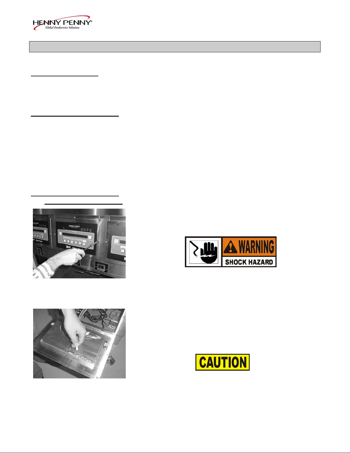
2-3. COMPLETE CONTROL
PANEL REPLACEMENT Should the control board become inoperative, follow these
instructions for replacing the board.
1. Remove electrical power supplied to the unit.
To avoid electrical shock or property damage, move the
POWER switch to OFF and disconnect main circuit
breaker, or unplug cord at wall receptacle.
2. Remove the four screws securing the control panel and lift
out.
3. Unplug the wire connectors going to the control board.
4. Install new control panel in reverse order.
When plugging connectors onto new control panel, be sure
the connectors are inserted onto all of the pins, and that the
connectors are not forced onto the pins backwards. If not
connected properly, damage to the board could result.
2-1 405
Page 11
Model OFE-321,322
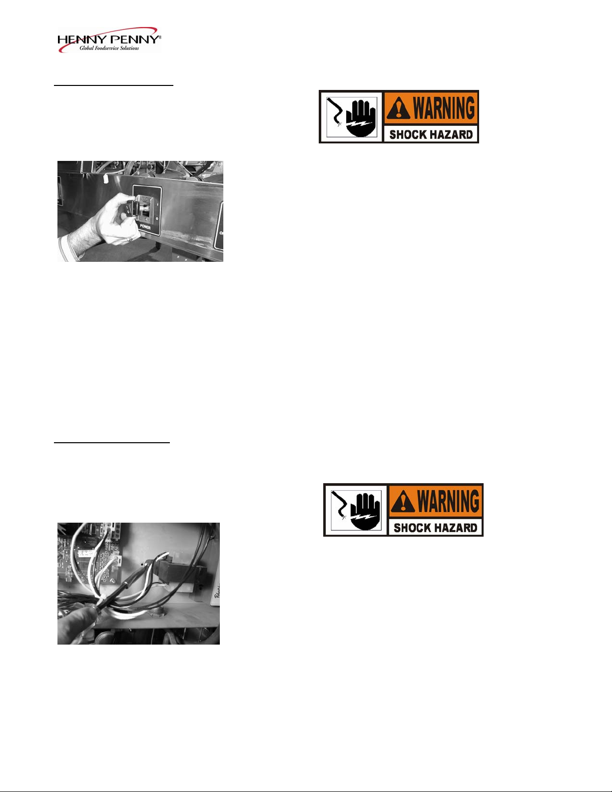
2-4. POWER SWITCH 1. Remove electrical power supplied to fryer.
To avoid electrical shock or property damage, move the
POWER switch to OFF and disconnect main circuit
breaker, or unplug cord at wall receptacle.
2. Remove control panel.
3. Label and remove the wires from the switch. With test
instrument, check across the terminals of the switch with
the switch in the ON position, then in the OFF position.
With the switch in the ON position, the circuit should be
closed. With the switch in the OFF position, the circuit
should be open. If the switch checks defective, replace by
continuing with this procedure.
4. With control panel removed, and the wires off the switch, push
in on tabs on the switch to remove from panel.
5. Replace with new switch, and reconnect wires to switch.
6. Replace the control panel.
2-5. TRANSFORMER The transformer reduces voltage down to accommodate those
components with low voltage.
1. Remove electrical power supplied to the unit.
To avoid electrical shock or property damage, move the
POWER switch to OFF and disconnect main circuit
breaker, or unplug cord at wall receptacle.
2. Remove the control panel as discussed in Complete Control Panel
Replacement Section.
3. Squeeze on the wire connector at the I/O board assembly to
disconnect the wires from the transformer.
4. Using a Phillips head screwdriver, remove the two screws
securing the transformer to the shroud.
5. Install the new transformer in reverse order.
405 2-2
Page 12
Model OFE-321,322
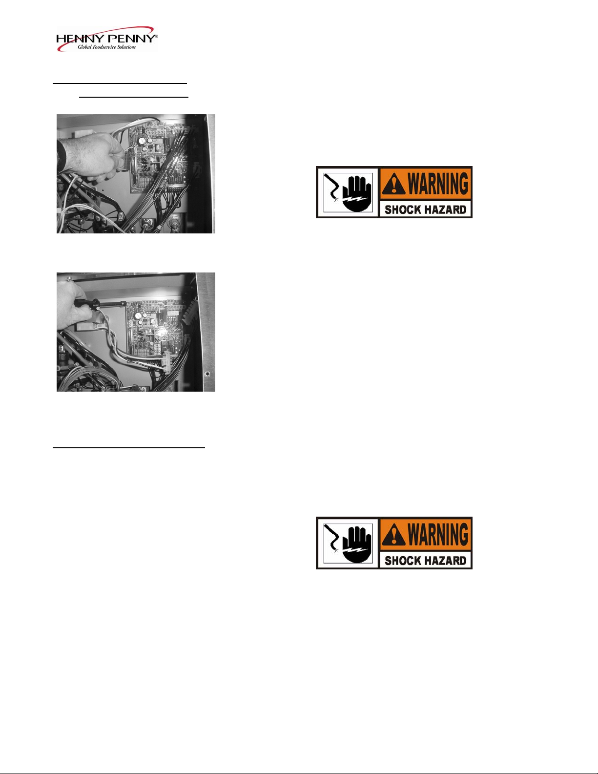
2-6. I/O POWER SUPPLY
BOARD ASSEMBLY The input/output power supply board assembly distributes
voltage to the various components in the fryer. The board also
receives information from components in the fryer.
1. Remove electrical power supplied to the unit.
To avoid electrical shock or property damage, move the
POWER switch to OFF and disconnect main circuit
breaker, or unplug cord at wall receptacle.
2. Remove the control panel as discussed in Complete Control
Panel Replacement Section.
3. Disconnect the wire assemblies from the board.
4. Using a nut driver or wrench, remove the four keps nuts
securing the board to the shroud.
5. Install the new I/O board assembly in reverse order.
2-7. DRAIN MICROSWITCH
Upon turning the drain handle, the drain microswitch circuit
should open, cutting off the pilot flame. This will prevent the fryer
from heating while shortening is being drained from the frypot.
1. Remove electrical power supplied to the unit.
To avoid electrical shock or property damage, move the
POWER switch to OFF and disconnect main circuit
breaker, or unplug cord at wall receptacle.
2-3 405
Page 13

2-7. DRAIN MICROSWITCH
(Continued)
2. The following check should be made to determine if the drain
3. Replace switch in reverse order.
2-8. FILTER SWITCH
1. Remove electrical power supplied to the unit.
Model OFE-321,322
microswitch is defective.
a. Remove the two screws securing the microswitch to the
drain rod valve bracket.
b. Remove wires from the switch.
c. Check for continuity across the two outside terminals of the
drain switch. If the circuit is open, the drain switch is
defective. The circuit should only be opened by pressing on
the actuator of the drain switch.
To avoid electrical shock or property damage, move the
POWER switch to OFF and disconnect main circuit
breaker, or unplug cord at wall receptacle.
2. Remove the control panel above the switch.
3. Label and remove the wires from the switch. With test
instrument, check across the terminals of the switch with the
switch in the ON position, and then in the OFF position. With
the switch in the ON position, the circuit should be closed.
With the switch in the OFF position, the circuit should be open.
If the switch checks defective, replace it by continuing with
this procedure.
4. With wires removed from the switch, push in on tabs on the
switch and remove switch from the panel.
5. Push new switch into panel and reconnect wires.
405 2-4
Page 14

2-9. HEATING ELEMENTS
Model OFE-321,322
Heating elements are available for 208 and 230 volts. Check
data plate to determine correct voltage.
Checkout:
If the shortenings temperature recovery is very slow or at a slower
rate than required, this may indicate defective heating element(s).
An ohmmeter will quickly indicate if the elements are shorted or
open.
1. Remove electrical power supplied to the frypot to be worked on.
To avoid electrical shock or property damage, move the
POWER switch to OFF and disconnect main circuit
breaker, or unplug cord at wall receptacle, to the frypot
to be worked on. Be aware the other controls will have
power.
2. Remove control panel.
3. Perform an ohm check on one element at a time, with wires
disconnected from element. If the resistance is not within
tolerance, replace the element.
Voltage Wattage Resistance Ohms (cold)
208 4800 9
230 4800 11
Replacement:
Refer to figure 2-2.
1. Drain the shortening from the frypot.
2. Remove the high limit bulb holder from the heating element
inside the frypot.
2-5 405
Page 15

Model OFE-321,322
2-9. HEATING ELEMENTS
(Continued) 3. Remove the heating element wires from the terminals by
removing the nuts and washers. Label each so it can be
replaced on the new element in the same position.
4. Remove the bolts from the five element spreaders. The
element spreaders will now pull off the elements.
5. Remove the brass nuts and washers which secure the ends of
the elements through the frypot wall.
6. Remove the heating elements from the frypot as a group by
lifting the far end and sliding them up and out toward the
rear of the frypot.
Always install new rubber O-rings when installing heater
elements.
7. Install new heating elements with the new O-rings, terminal
end first at approximately a 45° angle, slipping the terminals
through the front wall of the frypot.
8. Replace the brass nuts and washers on the element terminals.
Tighten the brass nuts to 30 foot lbs. of torque.
9. Evenly space the element spreaders on the sides of the
elements and reinstall bolts. Place the fifth spreader in the
front of the elements as to protect the temperature probe.
(Fig.2-1
10. Replace the high limit bulb holder on the top element, and
position the bulb between the top and second element
midway from side to side, and tighten screw that holds the
bulb in place.
11. Reconnect the wires to the appropriate terminal as labeled
when they were removed.
Temperature Spreader
Probe
Fig. 2-1 12. Replace the front control panel.
405 2-6
Page 16

Model OFE-321,322
2-9. HEATING ELEMENTS
(Continued) 13. Connect the power cord to the wall receptacle or close wall
circuit breaker.
Heating elements should never be energized without
shortening in the frypot, or damage to the elements could
result.
14. Replace the shortening in the frypot.
Fig. 2-2
2-7 405
Page 17

Model OFE-321,322
2-10. HEATING
CONTACTORS
Each well of an electric fryer requires two switching contactors.
The first in line is the primary contactor and the second in line is
the heat contactor. When open, the primary contactor does not
allow power to flow to the heat contactor. When closed, the
primary supplies voltage to the heat contactor. When the heat
contactor is open, no voltage is supplied to the heating elements.
When the heat contactor closes, voltage is supplied to the heating
elements.
Checkout (Power Removed)
1. Remove electrical power supplied to the frypot to be worked on.
To avoid electrical shock or property damage, move the
POWER switch to OFF and disconnect main circuit
breaker, or unplug cord at wall receptacle, to the frypot
to be worked on. Be aware the other controls will have
power.
2. Remove the control panel.
30 31 32 3. Perform a check on the contactor as follows:
From 30 to 34 open circuit
From 31 to 35 open circuit
33
From 32 to 36 open circuit
From 33 to 37 ohm reading 1700
Test Points Results
37
Wires should be removed and labeled to obtain an accurate check
of contactors.
34 35 36
Mercury Contactor
405 2-8
Page 18

Model OFE-321,322
2-10. HEATING Checkout (Power Supplied)
CONTACTORS
(Continued)
To avoid electrical shock, make connections before
applying power, take reading, and remove power before
removing meter leads. The following checks are
performed with the wall circuit breaker closed and the
main power switch in the ON position.
1. Re-apply power to unit and turn POWER switch ON.
2. Using illustrations from previous page, check voltage as
follows:
Test Points Results
From terminal 34 to 35 The voltage should read
From terminal 35 to 36 the same at each terminal
From terminal 34 to 36
Replacement:
If either contactor is defective it must be replaced as follows:
To avoid electrical shock or property damage, move the
POWER switch to OFF and disconnect main circuit
breaker, or unplug cord at wall receptacle, to the frypot
to be worked on. Be aware the other controls will have
power.
1. Remove only the wires directly connected to the contactor being
replaced. Label the wires for replacement.
2. Loosen the screws securing the contactor bracket to the shroud.
3. Remove the contactor from the bracket.
4. Reinstall in reverse order.
2-9 405
Page 19

Model OFE-321,322
2-11. SPEAKER ASSEMBLY
The speaker assembly emits audible signals to let the operator
know when cooking and hold times are finished.
1. Remove electrical power supplied to unit.
To avoid electrical shock or property damage, move the
POWER switch to OFF and disconnect main circuit
breaker, or unplug cord at wall receptacle.
2. Remove control panel.
3. Follow the speaker wire and disconnect from control board.
4. Remove the screws securing the speaker bracket to the shroud.
5. Remove the speaker from the bracket.
6. Reinstall in reverse order.
2-12. HIGH TEMPERATURE
LIMIT CONTROL The electric units, model OFE-321/2/3/4, use the same high
temperature control limits as the gas units, OFG-321/2/3/4, but
the mounting of the capillary tube is different on the electric
units compared to the gas units.
Checkout:
Use the same procedure as in the High Limit Temperature Control
(Gas) Section.
Replacement:
To avoid electrical shock or property damage, move the
POWER switch to OFF and disconnect main circuit
breaker, or unplug cord at wall receptacle, to the frypot
to be worked on. Be aware the other controls will have
power.
405 2-10
Page 20

Model OFE-321,322
2-12. HIGH TEMPERATURE 1. Drain the shortening from the frypot.
LIMIT CONTROL
(Continued)
2. Remove control panel.
3. Loosen small inside screw nut on capillary tube.
4. Remove capillary bulb from bulb holder inside the frypot.
5. Straighten the capillary tube.
6. Remove larger outside nut that threads into pot wall.
7. Remove the two screws that secure the high limit to the high
limit bracket.
8. Remove the defective control from the control panel area.
9. Insert new control and replace screws.
10. Uncoil capillary tube, starting at control, and insert through
pot fitting.
To avoid electrical shock or other injury, run the capillary
line under and away from all electrical power wires and
terminals. The tube must NEVER be in such a position
where it could accidentally touch the electrical power
terminals.
11. Carefully bend the capillary bulb and tube toward bulb holder
on heating elements.
12. Slip capillary bulb into bulb holder on heating elements.
Pull excess capillary line from pot and tighten nut into frypot
wall.
2-11 405
Page 21

Model OFE-321,322
2-12. HIGH TEMPERATURE
LIMIT CONTROL
(Continued)
Be sure capillary bulb of high limit is located behind
capillary bulb of thermostat. Both capillary bulbs
and bulb holders should be positioned as not to interfere
with basket or when cleaning the frypot wall, or damage to
capillary tube could result.
13. With excess capillary line pulled out, tighten smaller nut hand
tight, then ¼ turn with wrench.
14. Replace front panel.
15. Refill with shortening.
405 2-12
Page 22

Model OFE-321,322
2-13 405
Page 23

Model OFE-321,322
405 2-14
Page 24

Model OFE-321,322
LIMITED WARRANTY FOR HENNY PENNY APPLIANCES
Subject to the following conditions, Henny Penny Corporation makes the following limited warranties to the
original purchaser only for Henny Penny appliances and replacement parts:
NEW EQUIPMENT:
defective in material or workmanship within two (2) years from date of original installation, will be
repaired or replaced without charge F.O.B. factory, Eaton, Ohio, or F.O.B. authorized distributor. To
validate this warranty, the registration card for the appliance must be mailed to Henny Penny within ten
(10) days after installation.
REPLACEMENT PARTS:
be defective in material or workmanship within ninety (90) days from date of original installation will be
repaired or replaced without charge F.O.B. factory, Eaton, Ohio, or F.O.B. authorized distributor.
The warranty for new equipment and replacement parts covers only the repair or replacement of the defective
part and does not include any labor charges for the removal and installation of any parts, travel or other expenses
incidental to the repair or replacement of a part.
EXTENDED FRYPOT WARRANTY:
workmanship issues for a period of up to seven (7) years from date of manufacture. This warranty shall not cover
any frypot that fails due to any misuse or abuse, such as heating of the frypot without shortening.
0 TO 3 YEARS:
issues will be replaced at no charge for parts, labor, or freight. Henny Penny will either install a
new frypot at no cost or provide a new or reconditioned replacement fryer at no cost.
3 TO 7 YEARS:
issues will be replaced at no charge for the frypot only. Any freight charges and labor costs to
install the new frypot as well as the cost of any other parts replaced, such as insulation,
temperature temperature probes, high limits, fittings, and hardware, will be the responsibility of
the owner.
Any part of a new appliance, except lamps and fuses, which proves to be
Any appliance replacement part, except lamps and fuses, which proves to
Henny Penny will replace any frypot that fails due to manufacturing or
During this time, any frypot that fails due to manufacturing or workmanship
During this time, any frypot that fails due to manufacturing or workmanship
Any claim must be represented to either Henny Penny or the distributor from whom the appliance
was purchased. No allowance will be granted for repairs made by anyone else without Henny Penny’s
written consent. If damage occurs during shipping, notify the sender at once so that a claim may be
filed.
THE ABOVE LIMITED WARRANTY SETS FORTH THE SOLE REMEDY AGAINST HENNY PENNY
FOR ANY BREACH OF WARRANTY OR OTHER TERM. BUYER AGREES THAT NO OTHER REMEDY
(INCLUDING CLAIMS FOR ANY INCIDENTAL OR CONSQUENTIAL DAMAGES) SHALL BE
AVAILABLE.
The above limited warranty does not apply (a) to damage resulting from accident, alteration, misuse, or abuse;
(b) if the equipment’s serial number is removed or defaced; or (c) for lamps and fuses. THE ABOVE LIMITED
WARRANTY IS EXPRESSLY IN LIEU OF ALL OTHER WARRANTIES, EXPRESS OR IMPLIED,
INCLUDING MERCHANTABILITY AND FITNESS, AND ALL OTHER WARRANTIES ARE EXCLUDED.
HENNY PENNY NEITHER ASSUMES NOR AUTHORIZES ANY PERSON TO ASSUME FOR IT ANY
OTHER OBLIGATION OR LIABILITY.
Page 25

Model OFE-321,322
SECTION 3. PARTS INFORMATION
3-1. INTRODUCTION
OFE-321 & 322 Open Fryers.
3-2. GENUINE PARTS
lesser quality or substitute design may result in damage to the unit
or personal injury.
3-3. WHEN ORDERING
PARTS
Once the parts that you want to order have been found in the parts
list, write down the following information:
Item Number 8
Part Number 31561 Example:
Description On/Off Switch
From the data plate, list the following information:
Product Number 01400
Serial Number 0001 Example:
Voltage 208
3.4 PRICES
Your distributor has a price parts list and will be glad to inform
you of the cost of your parts order.
3.5 DELIVERY
Commonly replaced items are stocked by your distributor and will
be sent to you when your order is received. Other parts will be
ordered, by your distributor, from Henny Penny Corporation.
Normally, these will be sent to your distributor within three
working days.
3.6 WARRANTY
All replacement parts (except lamps and fuses) are warranted for
90 days against manufacturing defects and workmanship. If
damage occurs during shipping, notify the carrier at once so that
a claim may be properly filed. Refer to warranty in the front of this
manual for other rights and limitations.
405 3-1
This section lists the replaceable parts of the Henny Penny
Use only genuine Henny Penny parts in your fryer. Using a part of
Page 26

Model OFE-321,322
Figure 3-1. Electric Heat Controls
3-2 405
Page 27

Model OFE-321,322
FIGURE & PART NO. DESCRIPTION QTY. PER UNIT
ITEM NO. 321 322
3-1 ELECTRIC HEAT CONTROLS
1 26863 SPEAKER ASSY 1 2
2 24916 SPEAKER BRACKET ASSY. 1 2
3 60536 24V/230V TRANSFORMER ASSY. 1 2
4 27286RB I/O BOARD ASSY. 1 2
5 60241 425° HIGH LIMIT ASSY. 1 2
6 EF02-006 20A 250V FUSE HOLDER 2 4
6 EF02-007 15 AMP FUSE 2 4
7 14331 PROBE ASSY. 1 2
8 29510 24V MERCURY CONTACTOR 2 4
9 60810* I/O BOARD TO CONTROL CABLE - 4 PIN 1 2
10 60838* TRANSFORMER -480V TO 240V -
OFE-322 - 2
11 60847* TRANSFORMER MOUNTING BRACKET - 2
12 19923* TRANSFORMER-LARGE--480V-240V -
OFE-321 1 -
13 60722 BLOCK – 60 AMP FUSE (208-240V FRYERS) 1 2
14 EF02-122 FUSE – 45 AMP (208-240V FRYERS) 3 6
15 24347 ASSEMBLY – CURRENT SENSE XFORMERS 1 2
* Not Shown
405 3-3
Page 28

Model OFE-321,322
Figure 3-2. Side, Top, & Rear Panels
3-4 405
Page 29

Model OFE-321,322
FIGURE & PART NO. DESCRIPTION QTY. PER UNIT
ITEM NO. 321 322
3-2 SIDE, TOP, AND REAR PANELS
1 60293
2 FP01-082 CONNECTOR - 3/8 TUBE TO ½ NPT SS
3 FP01-087 ELBOW
TUBE, OIL RETURN LINE – OFE-322 - 1
– OFE-322 - 2
– OFE-322 - 1
4 NS02-002 NUT, END PANEL RETAINING 6 6
5 WA01-002 FLAT WASHER 6 6
6 SC01-216 SCREW 6 6
7 60552 SIDE PANEL, RH 1 1
8 59042 TOP REAR COVER (2 WELL) - 1
8 59043 TOP REAR COVER (1 WELL) 1 -
9 SC03-005 SCREW, BOX RETAINING 2 2
10 63097 TERMINAL BLOCK – 2 POLE 1 1
11 60312 CASTER 4 IN. W/O BRAKE 2 2
12 60551 SIDE PANEL, LH 1 1
405 3-5
Page 30

Model OFE-321,322
Figure 3-3. Oil Filtering System
3-6 405
Page 31

Model OFE-321,322
FIGURE & PART NO. DESCRIPTION QTY. PER UNIT
ITEM NO. 321 322
3-3 OIL FILTERING SYSTEM
1 66005 FRONT PLATE 1 -
2 17320 PIPE, FRONT 1 -
3 55152 DRAIN VALVE & COUPLING ASSY. 1 2
4 60736 DRAIN VALVE EXT. (ELECT.) (SN: GM024JB
& BELOW) 1 2
4 24643 DRAIN VALVE EXT. (ELECT.) (SN: GM025JB
& ABOVE) 1 2
5 16239 ELBOW, FILTER PUMP 1 -
6 67589 ASSY – FILTER PUMP & MOTOR 1 1
6 67583 FILTER PUMP MOTOR, 1/2 HP 1 1
7 17437 FILTER PUMP 1 1
8 26966 ASSY – POT TO PUMP TUBE – OFE-321 1 -
9 16809 NUT, FILTER TO VALVE TUBE 2 -
10 16808 FERRULE, FILTER TO VALVE TUBE 2 -
11 17407 ELBOW, FILTER PUMP TUBE 1 -
12 17306 TEE 1 -
13 50715 NIPPLE 1 -
14 17308 VALVE, FILTER 1 -
15 17334 QUICK CONNECT FITTING 1 -
16 SC03-005 SCREW, PLATE RETAINING 2 -
405 3-7
Page 32

Model OFE-321,322
Figure 3-4. Door, Switches, Menu Card, & Control Board
3-8 405
Page 33

Model OFE-321,322
FIGURE & PART NO. DESCRIPTION QTY. PER UNIT
ITEM NO. 321 322
3-4 DOOR, SWITCHES, MENU CARD, & CONTROL BOARD
1 67924RB 12 TIMER CONTROL BOARD ASSY. 1 2
2 60442 FILTER TO PUMP TUBE ASSY. 1 1
3 60501 RIGHT DOOR ASSY. (2 WELL) - 1
4 52064 4 IN. SWIVEL CASTER W/ BRAKE 2 2
5 60609 DECAL, FILTER POWER SWITCH 1 1
6 60844 SWITCH GUARD, FILTER SWITCH 1 1
7 43768 FILTER SWITCH 1 1
8 60608 DECAL, MAIN POWER SWITCH 1 2
9 60844 SWITCH GUARD, POWER SWITCH 1 2
10 43768 POWER SWITCH ASSY. 1 2
11 18227 DRAIN MICROSWITCH 1 2
12 NS02-005 NUT 2 4
13 18818 DRAIN VALVE EXTENSION ROD 1 2
13 66123 DRAIN VALVE HANDLE (SN HN048JC & ABOVE) 1 2
14 SC01-058 SCREWS, COVER & BRACKET RETAINING
(6-32 X 1.5 IN.) 2 4
15 SC03-005 SCREWS, BRACKET RETAINING 2 4
16 66008 DRAIN SWITCH BRACKET (OFE-322) - 2
16 66005 DRAIN SWITCH BRACKET (OFE-321) 1 17 60502 LEFT DOOR ASSY. (2 WELL) - 1
17 60542 DOOR ASSY. (1 WELL) 1 -
18 61724 CFA MENU CARD 1 2
19 69289 ASSY – FILTER UNION 1 1
20 18911* FILTER VALVE HANDLE (OFE-321) 1 -
* Not Shown
405 3-9
Page 34

Model OFE-321,322
Figure 3-5. Baskets and Return Faucet
3-10 405
Page 35

Model OFE-321,322
FIGURE & PART NO. DESCRIPTION QTY. PER UNIT
ITEM NO. 321 322
3-5 BASKETS AND RETURN FAUCET
1 26873 FRYPOT COVER 1 2
2 21033 HALF SIZE BASKET 2 4
2 69085 HALF SIZE BASKET – FRONT & REAR HOOK 2 4
3 FP01-087 ELBOW, MALE, 3/8 IN. 1 1
4 17333 FEMALE DISCONNECT 1 1
5 17334 MALE DISCONNECT 1 1
6 45402 RETURN FAUCET ONLY WITHOUT 17343
(322 & 324) 1 1
405 3-11
Page 36

Model OFE-321,322
Figure 3-6. Shrouds and Pot & Counter Top
3-12 405
Page 37

Model OFE-321,322
FIGURE & PART NO. DESCRIPTION QTY. PER UNIT
ITEM NO. 321 322
3-6 SHROUDS AND POT & COUNTER TOP
1 SC03-005 SCREW, BRACKET RETAINING, BOTTOM 2 2
2 SC01-034 SCREW, BRACKET RETAINING, TOP 2 2
3 60340 BRACKET, REAR SHROUD 1 2
4 63700 REAR SHROUD ASSY. 1 -
4 26870 REAR SHROUD ASSY. - 1
5 24899 POT & COUNTERTOP ASSY. (OFE-321) 1 -
5 24896 POT & COUNTERTOP ASSY. (OFE-322) - 1
6 60322 SHROUD CONTROL VERTICAL RH 1 1
7 60328 SHROUD CONTROL UPPER MIDDLE - 2
8 SC04-003 SCREW 4 9
9 60326 SHROUD CONTROL DIVIDER - 1
10 60605 BOTTOM SWITCH GUARD 1 -
10 60606 BOTTOM SWITCH GUARD - 1
11 SC1-034 SCREW 2 2
12 NS02-007 NUT 2 2
13 60324 SHROUD CONTROL VERTICAL LH 1 1
14 SC03-005 SCREW, SHROUD RETAINING 4 4
15 N02-006 NUT, SHROUD RETAINING 4 6
16 N02-006 NUT, RETAINER SECURING - 2
17 33261 REAR SHROUD RETAINER - 1
405 3-13
Page 38

Model OFE-321,322
Figure 3-7. Electric Heater
3-14 405
Page 39

Model OFE-321,322
FIGURE & PART NO. DESCRIPTION QTY. PER UNIT
ITEM NO. 321 322 323
3-7 ELECTRIC HEATER
1 30292-2 HEATING ELEMENT – 208V 7333W 3 6 9
1 30292-1 HEATING ELEMENT – 480V 7333W 3 6 9
2 26917 FRY BASKET SUPPORT 1 2 3
3 18720 HI LIMIT REAR CLAMP 1 2 3
3 18248 HI LIMIT FRONT CLAMP 1 2 3
4 SC01-053 CLAMP SCREW (#8-32 X 1/2 IN.) 1 2 3
5 SC01-055 SPREADER SCREW (#10-32 X 3/4 IN.) 10 20 30
6 LW02-005 LOCKWASHER, #10 INTERNAL 10 20 30
7 51931 SPREADER BAR ASSY. 5 10 15
405 3-15
Page 40

Model OFE-321,322
Figure 3-8. Drain Pan, Screen, and Cover
3-16 1104
Page 41

Model OFE-321,322
FIGURE & PART NO. DESCRIPTION QTY. PER UNIT
ITEM NO. 321 322 323
3-8 DRAIN PAN, SCREEN, & COVER
1 14673 KIT – 32X SS FILTER SCREEN ASSY 1 1 1
2 65211 CRUMB CATCHER 1 1 1
3 65447 BOTTOM FILTER SCREEN 1 1 1
4 17505 FILTER ENVELOPE CLIPS 2 2 2
5 69118 ASSY-32X SS FILTER SCREEN PIPE 1 1 1
6 69289 ASSY – FILTER UNION 1 1 1
7 60377 STANDPIPE TUBE 1 1 1
8 65208 NUT, FILTER 1 1 1
9 12102 FILTER ENVELOPE PAPER 5 5 5
10 21064 DRAIN PAN COVER (321) 1 - 10 24596 DRAIN PAN COVER (322, SN: GN046JB
AND ABOVE) - 1 10 60460 DRAIN PAN COVER (322, SN: GN045JB
AND BELOW) - 1 11 21088 DRAIN PAN (321) 1 - 11 66522 DRAIN PAN (322) - 1 12 03003 RINSE HOSE ASSY. 1 1 1
13 03495 ASSESSORY – DRAIN PAN DOLLY – 321 1 - 13 03496 ASSESSORY – DRAIN PAN DOLLY – 322 - 1 -
If unit has 3 filter screens, use part no. 14673
405 3-17
Page 42

Model OFE-321,322
Figure 3-9. Autolift Feature
3-18 405
Page 43

Model OFE-321,322
FIGURE &. PART NO. DESCRIPTION QTY. PER UNIT
ITEM NO. 321 322
3-12 AUTOLIFT FEATURE
1 50814 FRYPOT COVER, AUTOLIFT 1 2
2 50750 FILTER VALVE, OIL RETURN 1 1
3 50764 MICROSWITCH, RIGID LEVER 1 2
4 50716 ACTUATOR, AUTOLIFT, 24V MOTOR (SN: EN040JB)
& BELOW) 1 2
4 63602 ACTUATOR, AUTOLIFT, 24V MOTOR (SN: EN041JB
& ABOVE) 1 2
5 50780 TUBE, UNION TO WELL 2, FILTER SYSTEM - 1
6 50779 TUBE, UNION TO WELL 1, FILTER SYSTEM - 1
7 FP01-129 UNION, TEE, 3/8 IN. TUBE SS, FILTER SYSTEM - 1
8 50778 TUBE, PUMP TO UNION, FILTER SYSTEM - 1
9 50776 PIN, ACTUATOR CLEVIS 2 4
10 50865 BASKET HANGER ASSY. 2 4
11 31421 ...BEARING WITH SCREW 4 8
12 FP01-128 CONNECTOR (3/8 IN. TUBE TO 3/8 IN. NPT SS),
FILTER SYSTEM - 1
13 NS03-023* ...NUT, 1/4-20 ACORN CAP 4 8
14 50785 TUBE, OIL RETURN, LONG, FILTER SYSTEM - 1
14 60611 RETURN FAUCET ASSY. (
WITH 17334 DISCONNECT) 1 1
15 60796RB GM 12 BUTTON CONTROL (321) 1 2
16 61562 MENU CARD, AUTOLIFT 2 4
17 NS02-005 NUT 4 8
18 50290 BASKET LIFT PCB ASSY. 1 2
19 ME50-024 SPACER 4 8
20 30614 TRANSFORMER (208/240V-PRI, 24V-SEC.) 1 2
21 59721 RETURN VALVE HANDLE - 2
22 50704 1/2 SIZE BASKET 2 4
23 50703 FULL SIZE BASKET 1 2
24 60293 TUBE, OIL RETURN LINE 1 -
25 50786* TUBE, 2.00 NIPPLE, FILTER SYSTEM - 1
26 FP01-082 CONNECTOR (3/8 TUBE TO ½ NPT SS) 1 -
27 FP01-087 ELBOW 1 1
28 17333 DISCONNECT – FEMALE (USED W/60611) 1 1
* Not Shown
405 3-19
 Loading...