

559-734-7451 800-367-5480 FAX 559-734-7460
INSTALLATION INSTRUCTIONS
ADDA LEAF HELPER SPRING
Toyota Tacoma 4X4 with TRD 3 leaf spring
Thank you for purchasing a quality Hellwig Product.
PLEASE READ THIS INSTRUCTION SHEET COMPLETELY BEFORE STARTING YOUR INSTALLATION
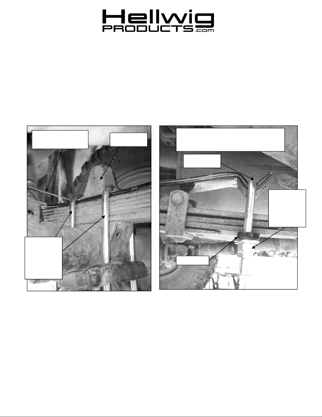
Spring is installed under
emergency brake cable
Toyota TRD
models with 3+
leaves —
replace Factory
U-bolts with Ubolts provided
Bump Stop
U-bolt Adjustment
All sides EXCEPT Driver’s side front.
See Important Note for Driver’s Side Front
U-Bolt
Adjust nuts to
desired tension
and double nut
to lock adjustment.
Crossbar
(979) 12/16/2011
559-734-7451 800-367-5480 FAX 559-734-7460
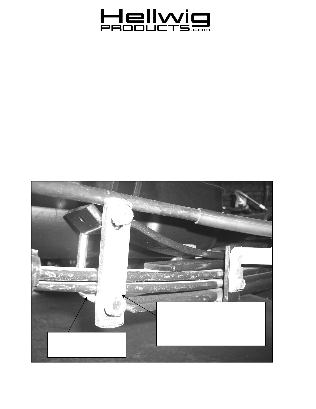
IMPORTANT NOTE
05-11 TOYOTATACOMA
APPLICATIONS
INSTALLATION OF THIS KIT ON 2005-11
TOYOTA TACOMAAPPLICATIONS REQUIRES
INSTALLATION OF SHACKLE KITAS
SHOWN ON DRIVER’S SIDE FRONT SPRING
NEXT TO FUEL TANK.
Compress spring with C-Clamp.
Install crossbar on outboard side of
spring and attach with lock nuts as
shown. Torque locknuts to 20-25 ft-
Install U-bolt as shown
with legs pointing out-
(979) 12/16/2011

559-734-7451 800-367-5480 FAX 559-734-7460
TORQUE TABLE
BOLT SIZE: 3/8” = 20-30 ft. lbs. – 7/16” =35-45 ft. lbs. – ½” = 50-70 ft. lbs. – 9/16” = 70-90 ft. lbs.
NOTE: Your spring may have a small hole in the end, this is for our manufacturing process and will not
be used.
1. On the driver’s side rear spring, remove U-bolts and bump stop at axle and place the helper spring on top of the main
spring and orient spring for best fit. DO NOT REMOVEU– BOLTS FROM BOTH SIDES AT THE SAME TIME.
2. Replace bumps top and fasten with 9/16” dia X 7-1/2” long U-bolts and nuts provided. Tighten U-bolts to 80-90 ft-
lb. Repeat process for passenger side.
3. Driver’s side front U-bolt— Compress spring with C-clamp and attach U-bolt as shown in Important Note # 50155
included in this kit.
4. Install adjustment U-bolts and install the crossbars with the washers and nuts.
5. Return the vehicle to the ground and adjust the U-bolts to desired height and tension. Double nut the U-bolts after
adjusting. The clearance between the helper spring and the truck spring should be no less than 1/4 inch.
6. Bounce the vehicle checking for clearance on all undercarriage components, brake lines, fuel lines, wiring, etc
IMPORTANT NOTE: This unit is designed to increase the level load carrying capacity of your vehicle. Never
load the vehicle this unit is installed on beyond the manufacturer’s maximum gross vehicle weight rating.
ATTENTION INSTALLER: BE SURE THE CUSTOMER RECEIVES THIS INSTRUCTION SHEET, ALL
IMPORTANT NOTE CARDS, WARNING CARDS, AND THE WARRANTY FORM.
(979) 12/16/2011
 Loading...