

Page 1
559-734-7451 800-367-5480 FAX 559-734-7460
INSTALLATION INSTRUCTIONS
6090Air Suspension Kit (pat. pending)
1999-2006 Tahoe, Suburban, Avalanche, Yukon
Thank you for purchasing a quality Hellwig Product.
PLEASE READ THIS INSTRUCTION SHEET COMPLETELYBEFORE STARTING
YOUR INSTALLATION
IMPORTANT NOTES
IF EQUIPPED WITH FACTORY PREMIUM RIDE OR
AUTOLEVELSUSPENSION, CONTACT HELLWIG
PRODUCTS CO. FOR FURTHER INSTRUCTIONS.
DO NOT INFLATE ANYAIR SPRINGASSEMBLY UNLESS IT HAS BEEN
PROPERLY INSTALLED ON VEHICLE.
DO NOT INFLATE AIR SPRINGS OVER 100 PSI
AMINIMUM OF 5-10 PSI MUSTBE MAINTAINED INAIR SPRINGS
AFTER INSTALLATION FOR WARRANTYTO BE VALID. FAILURE TO
KEEPMINIMUM PRESSURE INAIR SPRINGS WILLVOID WARRANTY.
THIS UNIT IS DESIGNED TO INCREASE THE LEVEL LOAD CARRYING
CAPACITY OF YOUR VEHICLE. NEVER LOAD THE VEHICLE THIS
UNIT IS INSTALLED ON BEYOND THE MANUFACTURER’S MAXIMUM
GROSS VEHICLE WEIGHT RATING.
OVERINFLATIONAND IMPROPER USE MAY RESULT IN PERSONAL
INJURYAND/OR DAMAGE TO YOUR VEHICLEAND PROPERTY.
6090 ( R-6090) 03/09/07
Page 2
559-734-7451 800-367-5480 FAX 559-734-7460
BEFORE STARTINGYOUR PROJECT
WHEN LIFTING A VEHICLE WITH A JACK, BE SURE TO SET THE PARKING BRAKE AND USE SAFETY STANDS.
ENSURE THAT THE INSTALLATION OF COMPONENTS WILL NOT CRUSH OR DAMAGE FUEL AND BRAKE
LINES OR ELECTRICAL HARNESSES.
BEFORE DRILLING ANYHOLES, ENSURE THAT ALL ELECTRICAL WIRES, FUELLINES, BRAKE LINES, BRAKE
HOSES AND ANY OTHER COMPONENTS ARE MOVED OR PROTECTED TO AVOID DAMAGE FROM DRILLING
ANY HOLES .
DO NOT ATTEMPT ANY MODIFICATIONS TO THE VEHICLE OTHER THAN THOSE OUTLINED IN THIS
INSTRUCTION SHEET. IF ANY INTERFERENCE WITH THEGAS TANK, FUEL LINES, BRAKE LINES, EXHAUST
PIPE, ETC. EXISTS, STOP YOUR INSTALLATIONAND CALL HELLWIG PRODUCTS FOR TECHNICAL HELP.
IF WHEELS ARE REMOVED FOR INSTALLATIONOF KIT, CHECK MANUFACTURERS SPECIFICATIONS FOR
PROPER LUG NUT TORQUE BEFORE REINSTALLING WHEELS.
WHEN CUTTING AIRBRAKE TUBING, A SQUARE CUT IS REQUIRED AND THE HOSE END MUST NOT BE
DEFORMED OR LEAKAGEMAY RESULT. IF DEFORMATION OF THE HOSE END OCCURS, THE HOSE END
MUST BE REWORKED SO THAT IT IS ROUND.
ENGAGEMENTOF THE SEALING O-RING WILL BE FELT WHEN THE AIR LINE HAS BEEN INSERTED
PROPERLY INTO THE FITTING. FITTINGS MAY BE DISCONNECTED IF REQUIREDBY PUSHING DOWN ON THE
OUTER RING WHILE PULLING FIRMLY ON THE AIR LINE.
ROUTE AIRLINES AWAY FROM EXHAUST PIPES OR ANY OTHER SOURCESOF HEAT AND ENSURE THAT THE
AIR LINES ARE PROTECTED FROM SHARP EDGES.
6090 ( R-6090) 03/09/07
Page 3
PartA Air Spring Installation
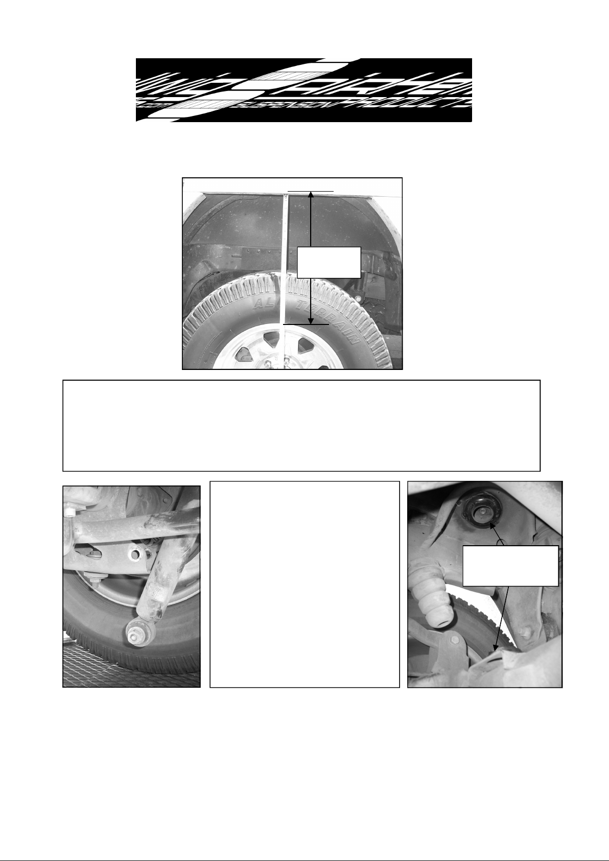
Measure this
distance
1. Prepare vehicle for installation by chocking front tires and setting emergency
brake. Before starting installation, measure the distance from the top of rear
wheel to fender lip as shown. This is the original ride height of the vehicle.
Write this measurement down as this will be used to set the height of the air
springs later in the installation.
2. For ease of installation, position the rear wheels on automotive ramps. Ensure vehicle is
secure and disconnect shock
absorbers from rear axle. Raise
Remove insulators
from frame and axle
vehicle frame until coil springs
are unloaded. Support frame
with jack stands and remove
coil springs and insulators from
vehicle. Do not remove bump
stops from frame.
6090 ( R-6090) 03/09/07
Page 4
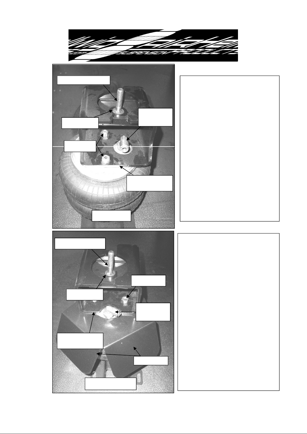
7/16UNF x 2-1/4 Bolt
Push Nut Clip
3/8 UNF Nut
Driver Side
1/2 MPT x 3/8
Hose fitting
This side of bracket
faces inboard
3. Prepare driver side air spring
assembly by installing 1/2” MPT
x 3/8 push to connect fitting into
air spring. Torque to 25-30 ft-lb.
The driver side frame bracket
has a full circle cut out for the
air fitting instead of a cut-out on
the edge. Attach frame bracket
to air spring with 3/8” UNF nuts.
Torque to 20 ft-lb. Place 7/1620x2-1/4” bolt through hole in
frame bracket and retain with
push nut clip. Push nut can be
installed on bolt by pushing on
clip with a deep well socket
while holding head of bolt in
place.
7/16UNF x 2-1/4 Bolt
Push Nut Clip
This side of bracket
faces inboard
Passenger Side
3/8 UNF Nuts
1/2 MPT x 3/8
Hose fitting
Heat Shields
4. Prepare passenger side air
spring assembly by installing
1/2” MPT x 3/8 push to connect
fitting into air spring. Torque to
25-30 ft-lb. The passenger side
frame bracket has a cut-out on the
edge of the bracket for the air fitting. Place two (2) heat shields
on top of air spring as shown and
attach frame bracket to air spring
with 3/8” UNF nuts. Torque to
20 ft-lb. Place 7/16-20x2-1/4”
bolt through hole in frame
bracket and retain with push nut
clip. Push nut can be installed on
bolt by pushing on clip with a
deep well socket while holding
head of bolt in place.
6090 ( R-6090) 03/09/07
Page 5
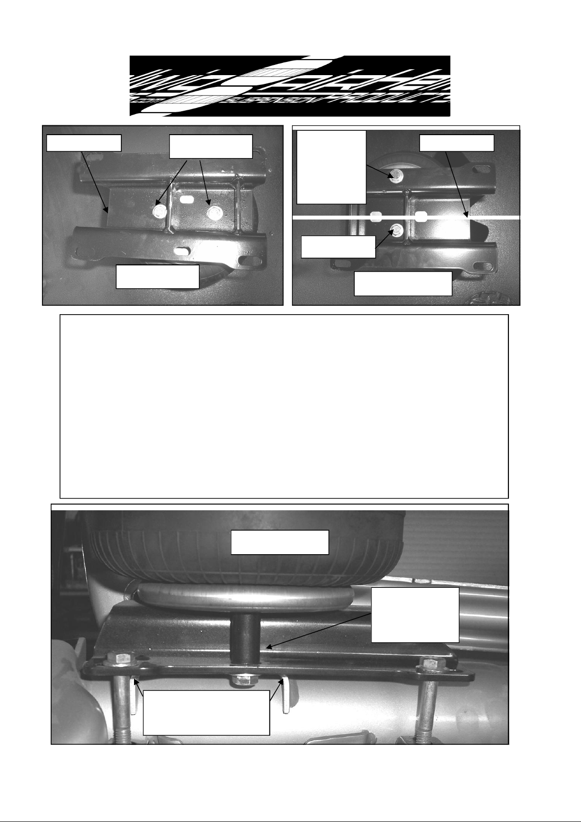
This end inboard This end inboard
3/8-16 x 1” Bolt
3/8-16 x 1-3/4”
Bolt Install 11/4” spacer
tube between
bracket and air
spring
3/8-16 x 1” Bolt
Driver Side
Passenger Side
5. Attach axle bracket to air spring as shown. The reinforcement braces are to be
installed over the coil seat on the axle. Note that the bracket is installed so that
the braces are under the air spring. The section of the axle bracket without
braces will be installed so that it faces inboard toward the center of the axle.
There are differences in how the brackets attach to the air spring for the driver
and passenger assemblies. On the passenger side assembly attach the 3/8-16 x
1-3/4” bolt and 1-1/4” spacer to air spring and axle bracket as shown. Then attach 3/8-16 x 1” bolt to air spring through middle hole of axle bracket as shown.
Snug bolts but do not tighten to allow for adjustment. On the driver side assembly attach the axle bracket to the air spring using the slotted holes as shown using 3/8-16 x1” bolts. Snug bolts but do not tighten to allow for adjustment.
Passenger Side
3/8-16 x 1-3/4” Bolt
Install 1-1/4” spacer
tube between
bracket and air
Coil spring seat—install
bracket so that reinforcement
braces center bracket on seat.
6090 ( R-6090) 03/09/07
Page 6
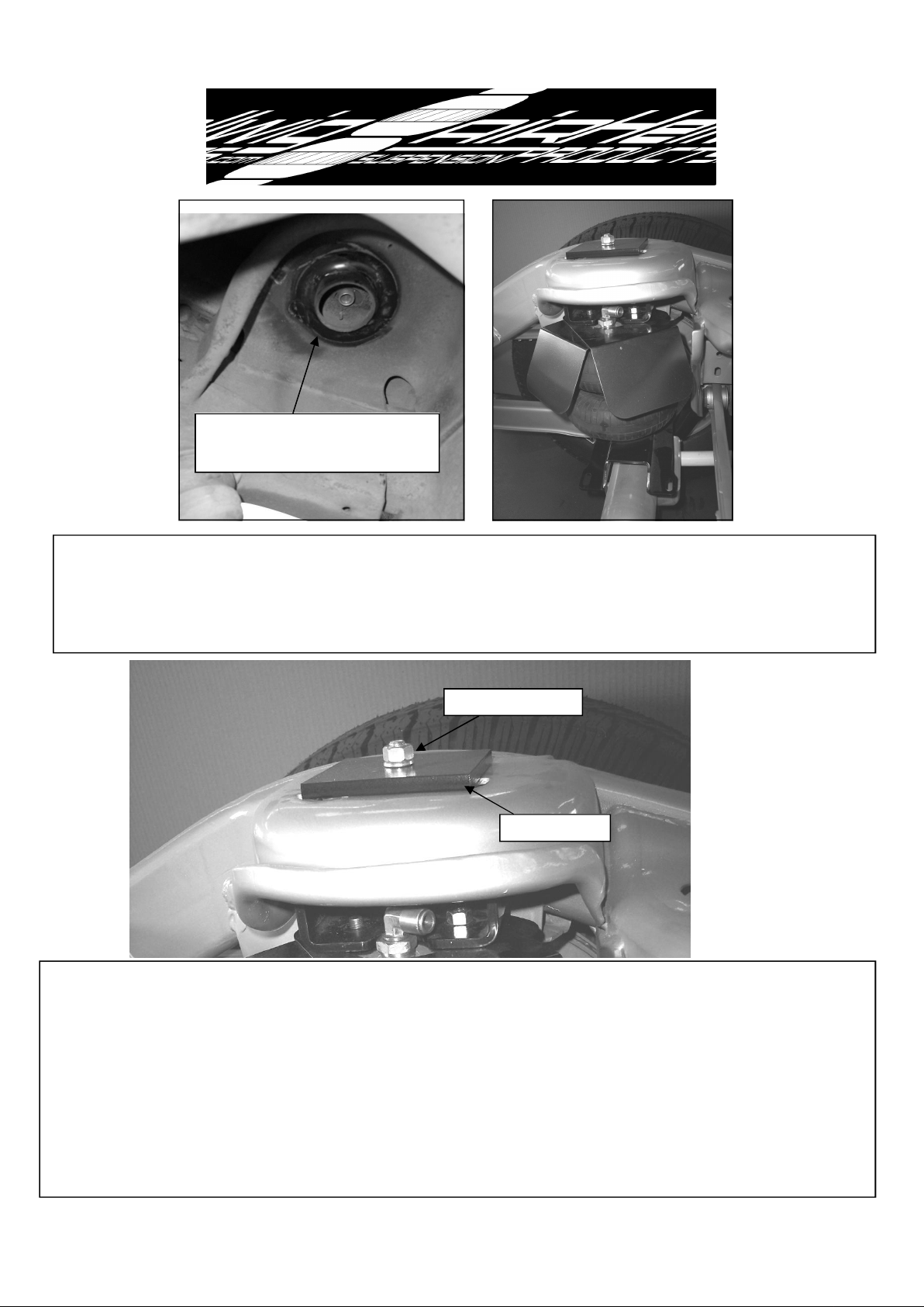
Place frame bracket over coil spring
seat
6. Compress air spring assembly and install between axle and frame. Place brackets over
coil spring seats so that the cut-out in the frame bracket and the reinforcements in the axle
bracket fit over the raised lip of the seat. Adjust axle brackets so that air springs sit square
and tighten bolts to 20 ft-lb. Heat shields may need to be bent slightly to clear exhaust pipe.
Nut and lock washer
Frame Washer
7. To aid assembly of brackets to frame, lower frame of vehicle slightly so that the air spring
assembly holds itself in place between the axle and frame. While lowering frame, DO NOT
get under vehicle or place hands between axle and frame. Place frame on jack stands before
continuing work. Attach frame bracket by placing frame bracket over coil spring seat so that
the cut-out in the frame bracket fits over the raised lip of the seat. Place frame washer over
bolt and attach bracket with 7/16”nut and lock washer. Tighten 7/16” bolt to 35-40 ft-lb.
Due to the close quarters of the body and frame it is advised to hold the nut in place with a
wrench and tighten the bolt head. To gain additional clearance to tighten the nut, the plastic
inner fender wells can be unbolted.
6090 ( R-6090) 03/09/07
Page 7
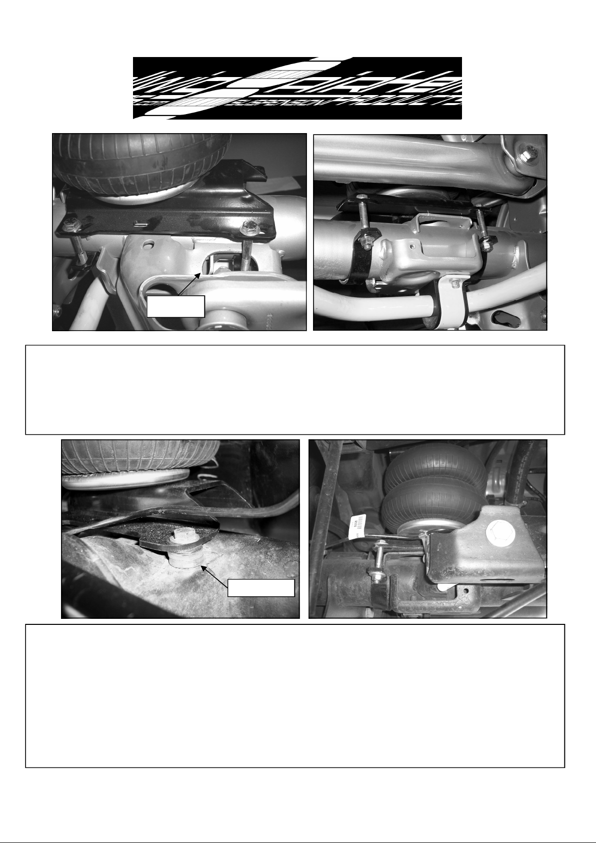
Slotted hole
8a. 1999– early 2006 models—Driver side panhard axle bracket has a large slotted hole to
insert bolt through as shown. Place 3/8-16x2-3/4” bolts through slotted holes in axle bracket
as shown and attach qty 2 axle straps per side to axle using washers and 3/8” locknuts.
Tighten nuts until legs of axle straps bend slightly. Relocate brake lines so that they do not
interfere with axle brackets, bolts, straps and air springs.
Thick washers
8b. Late 2006 models - Driver side panhard axle bracket does not have a large slotted hole.
Place 3/8-16x2-3/4” bolts through slotted holes in axle bracket as shown and attach qty 2 axle
straps to passenger side axle bracket using washers and 3/8” locknuts. Attach 1 axle strap to
outboard side of axle bracket only as shown for early models. Place qty (2) 1/4” thick washers between axle bracket and panhard axle bracket as shown. Shim axle bracket with additional flat washers until bracket is parallel with axle. Insert 3/8-16 x 1-1/2 bolt and tighten
locknut to 20 ft-lb. Tighten nuts on axle straps until legs of axle straps bend slightly. Relocate brake lines so that they do not interfere with axle brackets, bolts, straps and air springs.
6090 ( R-6090) 03/09/07
Page 8
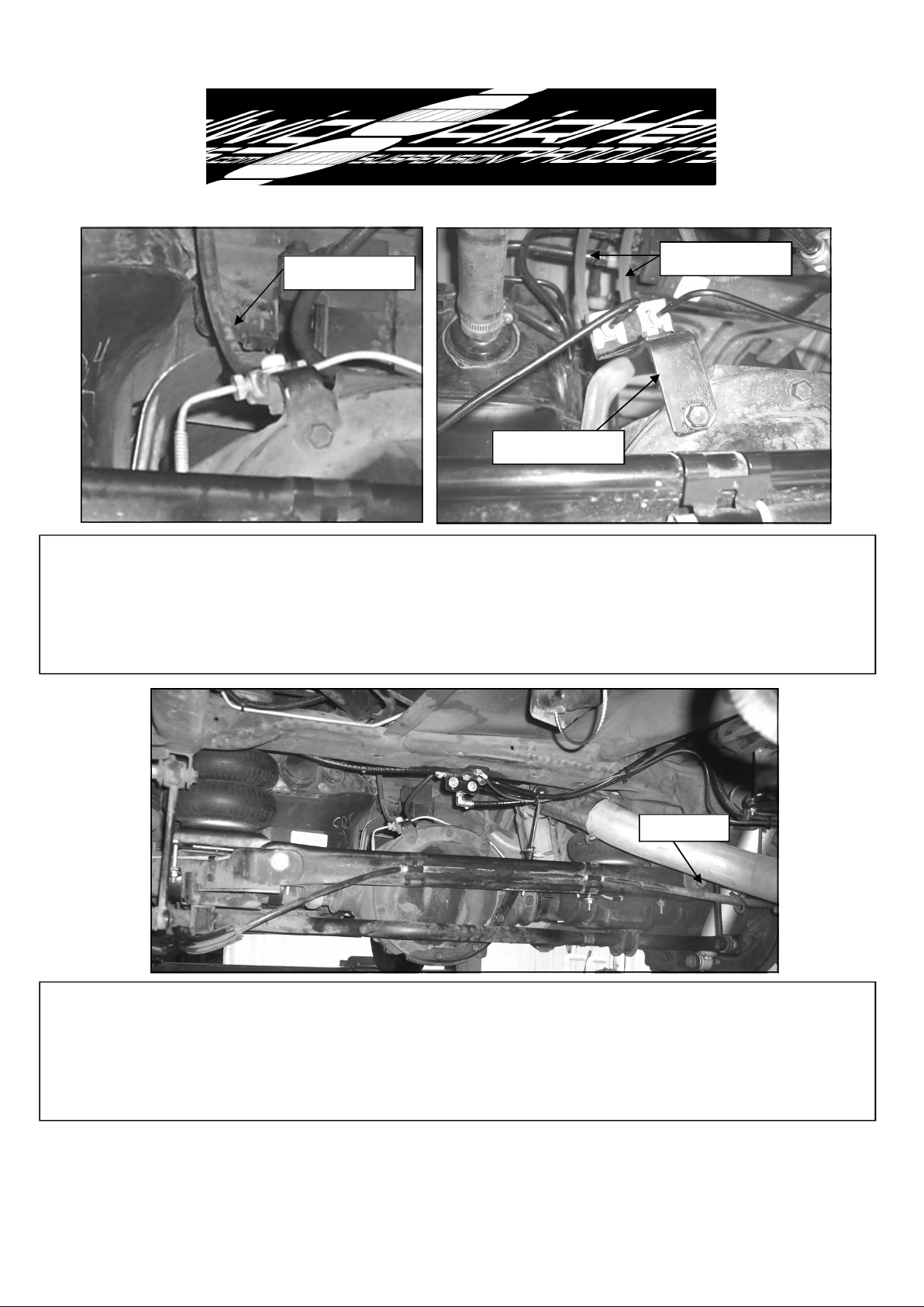
Single brakehose.
Relocation Bracket
Dual brake hose.
9. If vehicle has a single brake hose go to step 10. If the vehicle has two brake hoses as
shown, remove factory bracket and install brake relocation bracket using 5/16” bolt and nut to
attach brake hoses to bracket. Failure to properly install bracket will result in contact between
the brake lines and leveling valve.
Panhard bolt
10. Recheck all fasteners for proper torque and ensure adequate clearance to all vehicle components – exhaust, brake hoses, brake lines, shocks, differential, etc. Make sure that passenger
side panhard bolt will not contact air spring during use. A minimum of 1/2” clearance is required. If necessary, remove and re-install panhard bolt with bolt head facing air spring to
provide clearance.
6090 ( R-6090) 03/09/07
Page 9
559-734-7451 800-367-5480 FAX 559-734-7460
Part B Leveling Valve Installation
Subtract 1” from
reference dimension
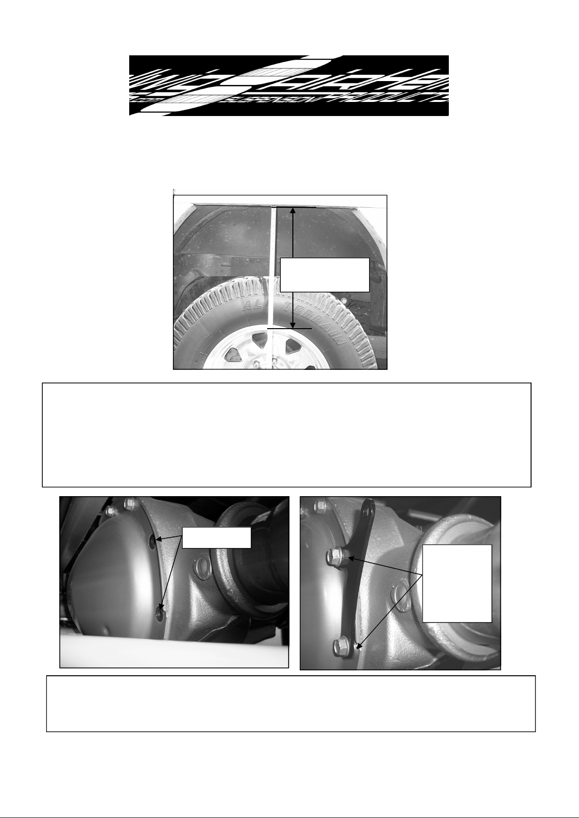
11. Reference the ride height from step (1) and subtract 1” from this measurement. Adjust frame height to the new measurement and place frame on jack stands. This will allow the vehicle to have a level attitude as GM built in rake to accommodate compression of the coil spring under load. The air suspension will hold ride height regardless of
load. IMPORTANT- You must reduce the rear ride height 1” to prevent the leveling
valve linkage from contacting the floorpan.
Remove 2 bolts
Qty (2) 5/16”
washers between bracket
and cover at
each bolt location .
12. Remove 2 bolts from differential cover as shown. Re-use bolts to attach leveling
valve axle bracket as shown. Place qty (2) 5/16” washers between differential cover and
bracket at each bolt location to make bracket sit square. Torque to 10-12 ft-lb.
6090 ( R-6090) 03/09/07
Page 10
559-734-7451 800-367-5480 FAX 559-734-7460
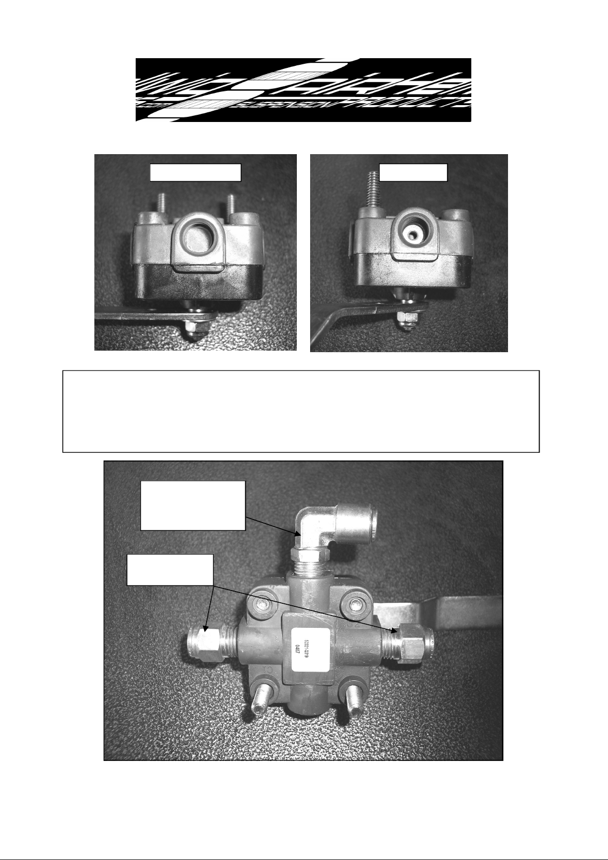
Inlet/Exhaust Port Delivery Port
13. Prepare leveling valve for installation. The inlet and exhaust ports have a
screen across the base of the port while the delivery ports to the air springs have a
hole. See photos. Attach fittings to leveling valve as shown below. Torque fittings to 7-8 ft-lb. Do not overtighten.
3/8” tube –1/4” MPT
elbow (fitting may have
plastic elbow)
3/8” tube—1/4”
MPT connector
6090 ( R-6090) 03/09/07
Page 11
559-734-7451 800-367-5480 FAX 559-734-7460
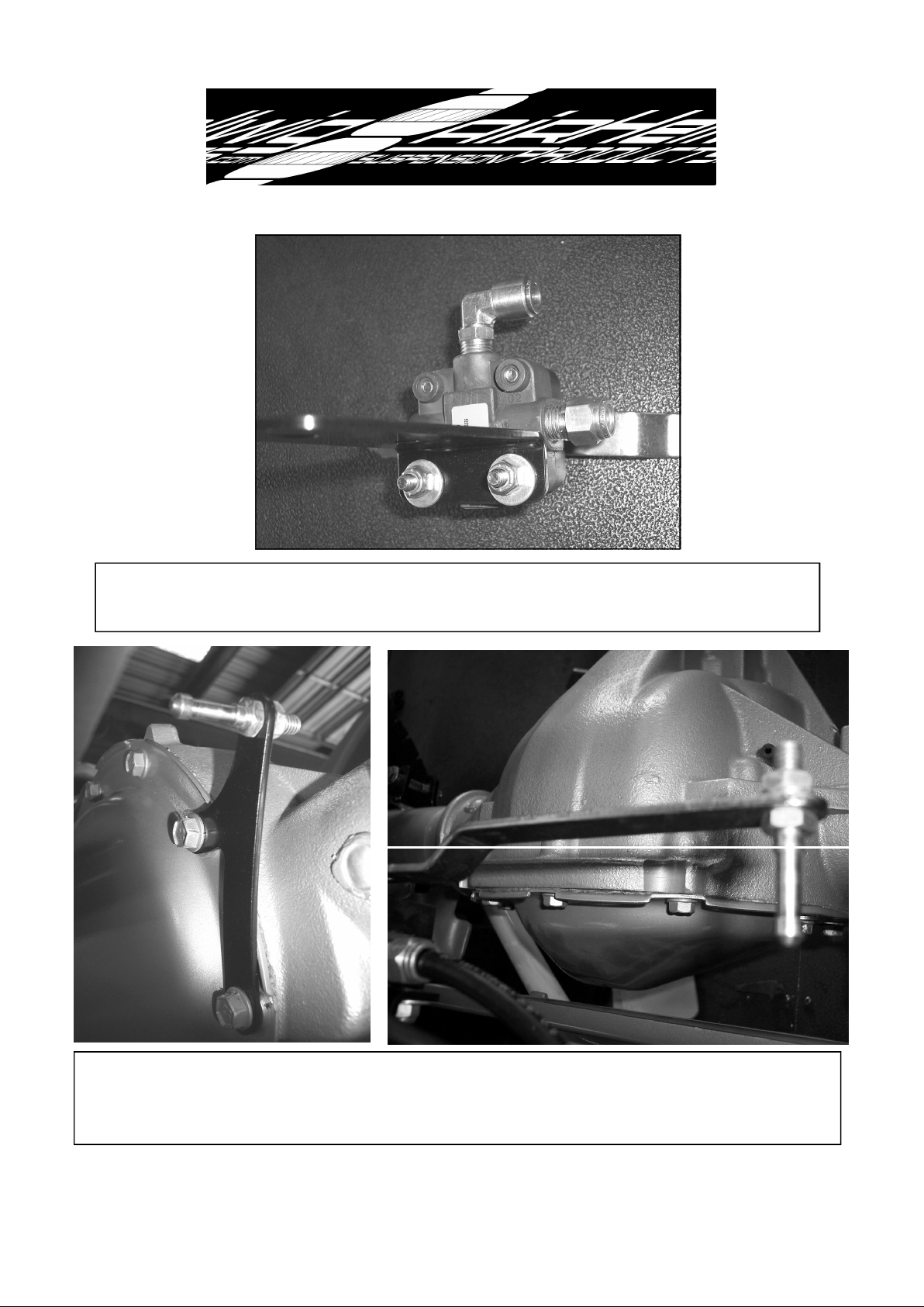
14. Attach leveling valve bracket to valve as shown using 1/4” nylon locknuts
and washers. Tighten to 7 ft-lb.
15. Attach leveling valve linkage pins to valve and axle bracket in orientation shown.
Make sure that the axle bracket and linkage pin will not interfere with brake lines. Relocate brake lines as required. Tighten nuts to 8-10 ft-lb.
6090 ( R-6090) 03/09/07
Page 12
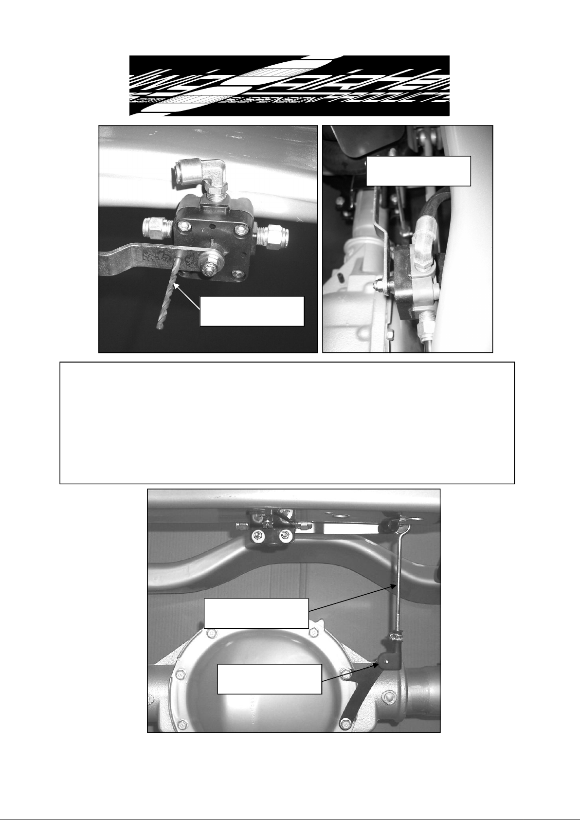
Locate valve as close to
crossmember as possi-
Center lever arm on
valve with 11/64” drill
16. Assemble linkage as shown in photos and clamp leveling valve bracket to
frame crossmember in location shown so that linkage geometry matches photo.
Make sure leveling valve is as close to crossmember as possible to provide axle
clearance when suspension compresses. DO NOT drill mounting holes at this
time. Center leveling valve by inserting a 11/64” drill bit through hole in arm and
body of leveling valve. When satisfied with linkage geometry, REMOVE drill
bit.
Linkage to be vertical
for initial layout.
Link must be attached as
shown for initial layout.
6090 ( R-6090) 03/09/07
Page 13
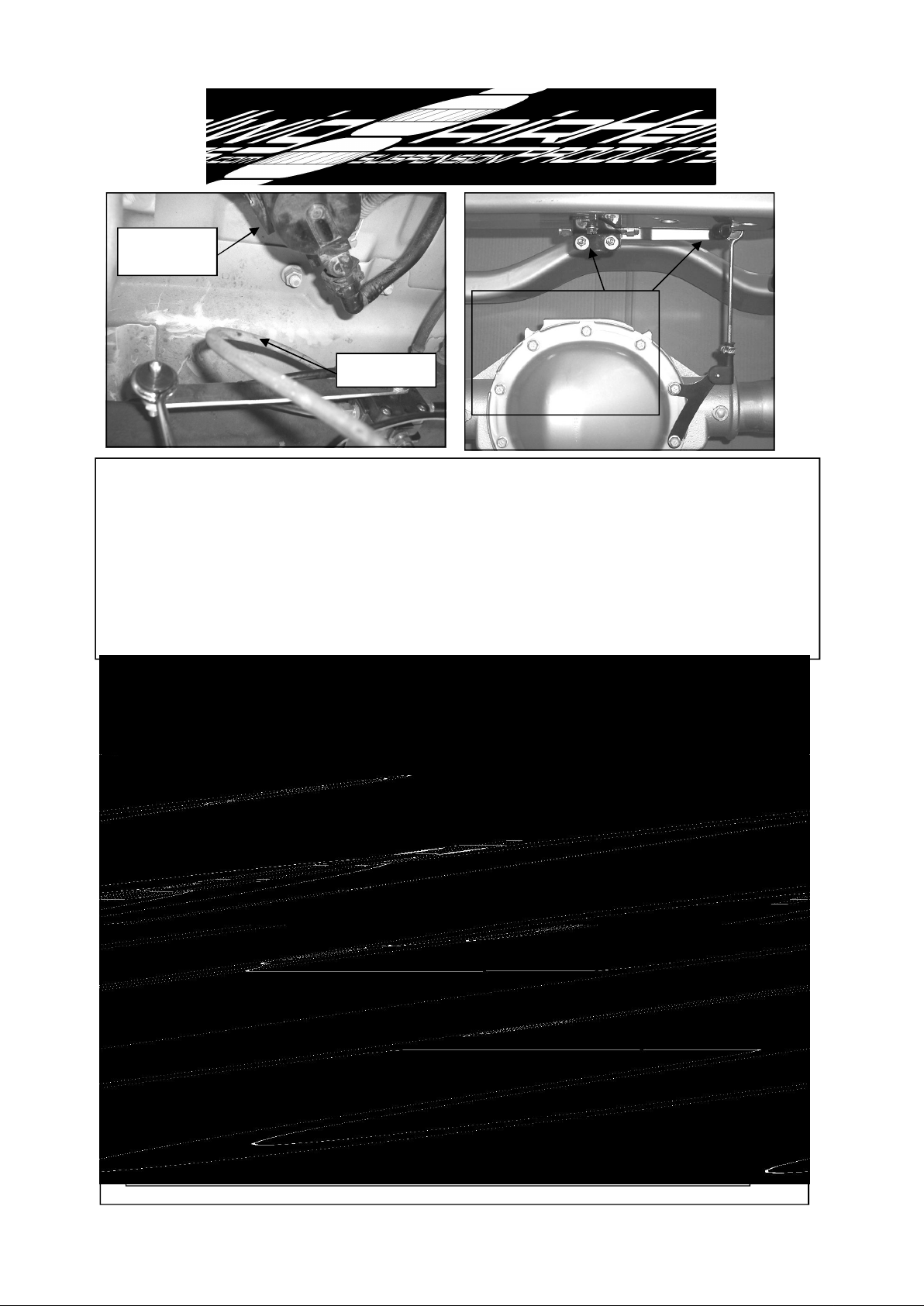
Evaporative
canister.
IMPORTANT: Ensure leveling valve and linkage will
not contact the floor, axle,
Vent Tube
or evaporative canister
when full weight of vehicle
is on the bumpstops.
17. IMPORTANT– BEFORE DRILLING ANY MOUNTING HOLES IN CROSSMEMBER, remove jack stands and lower frame so that the weight of the vehicle is on
the bumpstops. CHECK POSITION OF LEVELING VALVE SO THAT IT CLEARS
AXLE ASSEMBLY AND BRAKE LINES. It will be a close fit but there should be at
least 1/2” of clearance. Relocate brake lines if required. Also check that the leveling
valve arm will not contact the floor of the vehicle or any other components—
evaporative canister, vent tube, exhaust pipe, etc. After verifying clearances proceed to
step 18—Do not drill holes at this time.
Leveling Valve Clearances with vehicle on bumpstops
Check position of leveling
valve so that at least 1/2” clearance is maintained to axle and
Leveling Valve clearance must be checked with weight of vehicle
on bumpstops before drilling any mounting holes.
Maintain at least 1” clearance
to vehicle floor when weight
of vehicle is on bumpstops.
6090( R-6090) 03/09/07
Page 14
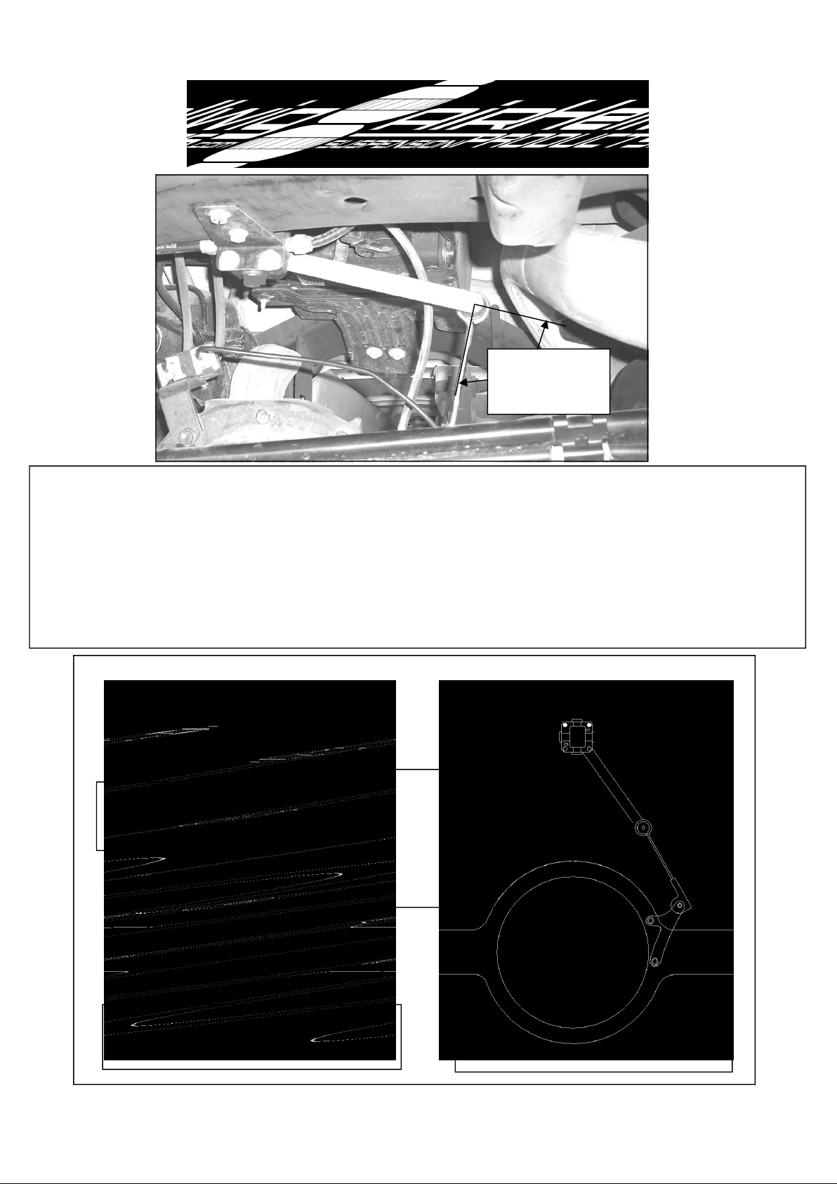
20 deg minimum
angle required at
full extension
18. Reconnect shock absorbers to axle brackets and torque bolts to 60-70 ft-lb. IMPORTANT— Raise
vehicle frame until the wheels come off the ground and support frame on jack stands. Note orientation
of leveling valve linkage. The leveling valve arm and link must NOT be in line when the suspension is
at full extension or the valve will not operate properly. Ensure there is at least a 20 degree angle between the lever arm and linkage at full extension . The leveling valve can be moved toward the passenger side frame rail to increase this angle. The leveling valve MUST be RECHECKED at compression
and nominal ride height if the leveling valve is moved to ensure that the arm and linkage will not contact
the vehicle or any of its components.
Leveling valve orientation at full extension
Angle between linkage
and lever arm maintained at full extension
Good Installation—Leveling
valve will work correctly
6090 ( R-6090) 03/09/07
Lever arm and linkage point at
each other at full extension
which will result in damage to
lever arm, valve and linkage.
Correct by moving leveling
valve toward passenger side
frame rail until minimum angle
Bad Installation—Leveling
valve will not work correctly
Page 15
559-734-7451 800-367-5480 FAX 559-734-7460
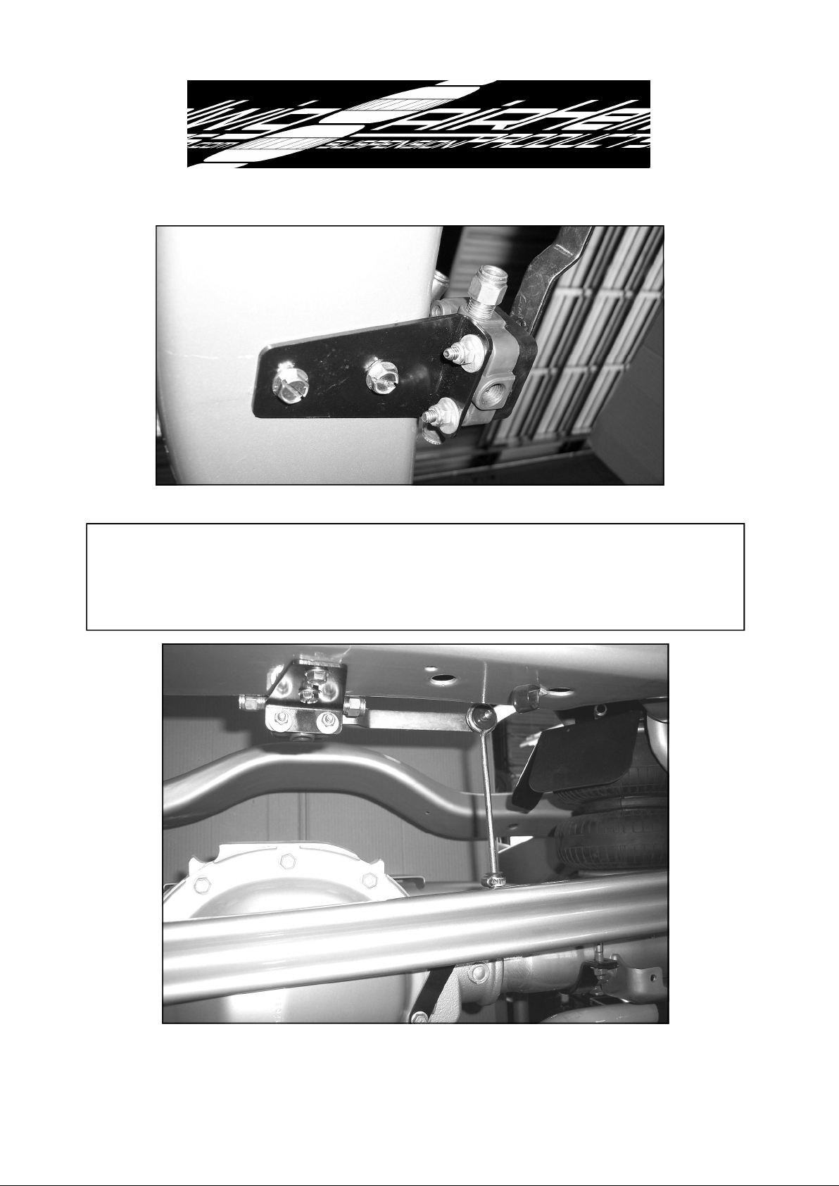
19. When satisfied with position of leveling valve and linkage has been checked
for proper operation and clearance, mark hole location to attach leveling valve
bracket to crossmember. Drill (2) 1/4” holes and install (2) 5/16” self tapping
bolts to attach bracket to crossmember. Torque bolts to 10 ft-lb
6090 ( R-6090) 03/09/07
Page 16
559-734-7451 800-367-5480 FAX 559-734-7460
Part C Compressor Installation
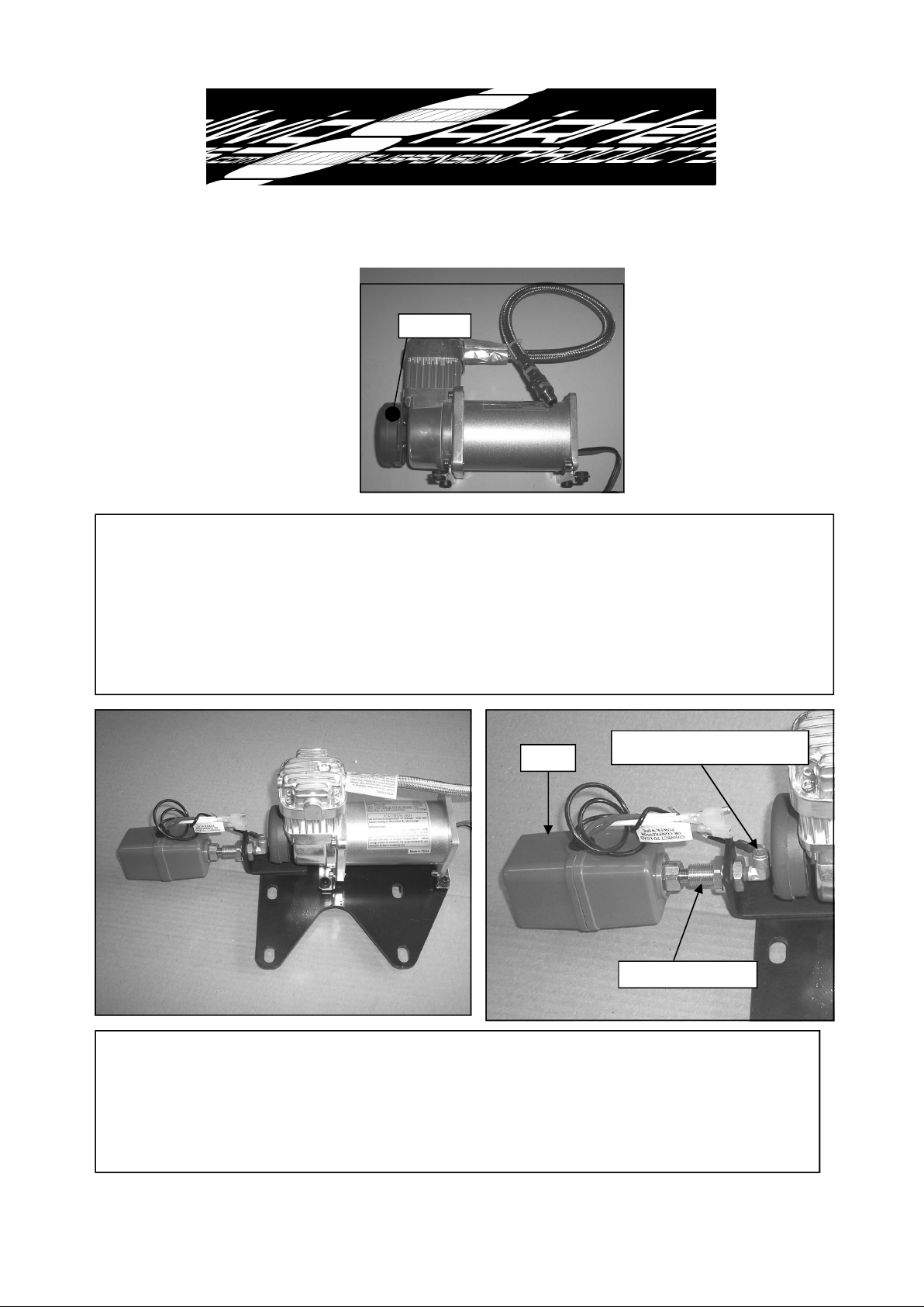
Air Filter
20. Prepare the compressor for mounting by HAND-TIGHTENING the air filter
into the port on the compressor. If necessary, adapters are provided with the compressor to connect nylon hose from the tank to the compressor hose. Do not remove the braided hose or check valve from the compressor. If the vehicle will be
operated in a manner where the compressor may draw in water, the air filter
should be remotely mounted with components included with compressor.
Relay
1/4” Tube—1/8” MPT Elbow
!/8” NPT Bulkhead
21. Attach 1/8” NPT bulkhead to relay bracket and fasten to mounting plate using
1/4” hardware. Attach 1/4”x 1/8” MPT elbow to bulkhead. Attach relay to opposite end of bulkhead as shown. Use pipe sealant or Teflon tape (provided) on
all connections. Attach compressor to mounting plate as shown using hardware
provided.
6090 ( R-6090) 03/09/07
Page 17
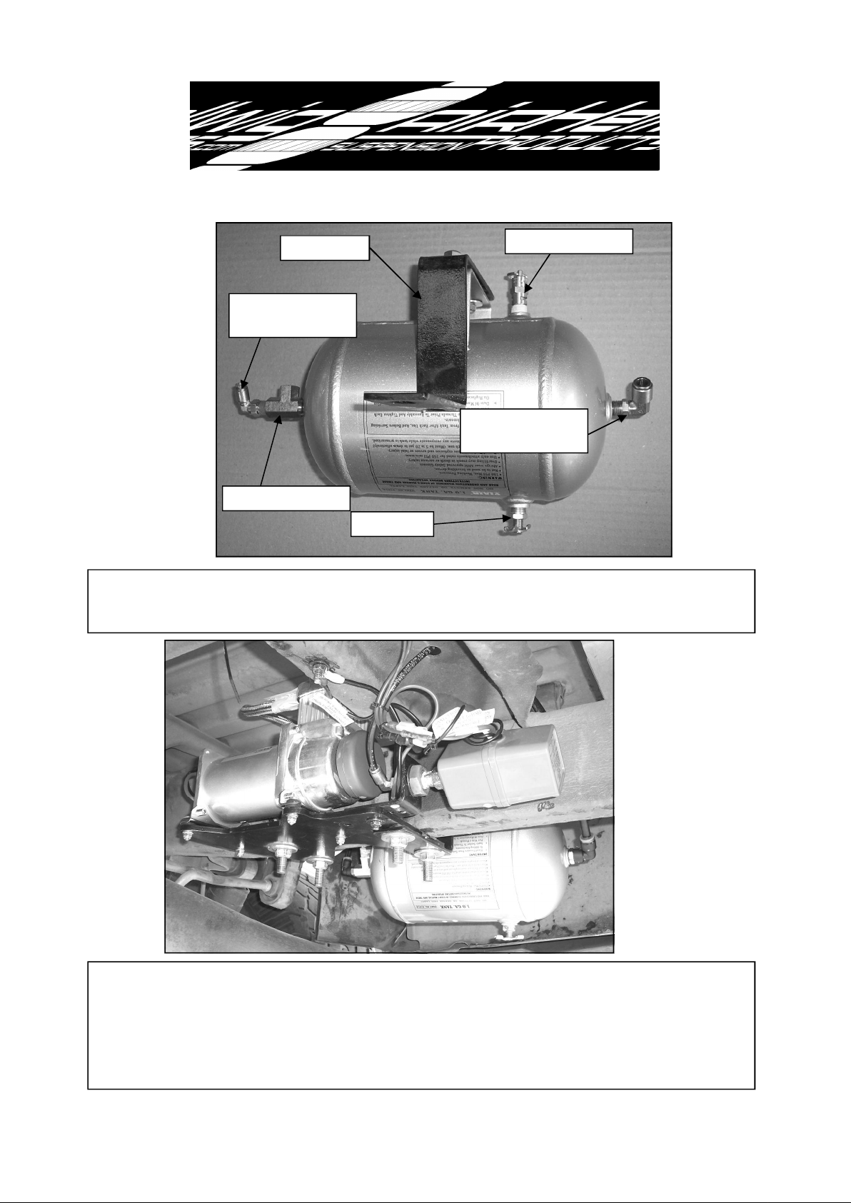
559-734-7451 800-367-5480 FAX 559-734-7460
Tank Bracket
1/4” Tube X 1/4”
MPT Elbow
3/8” Tube X 1/4”
MPT Elbow
1/4” Street Tee
Drain Valve
Blowoff Valve
22. Prepare air tank as shown. Apply pipe sealant or Teflon tape to all fittings.
Attach tank to tank bracket with 3/8-16 x 1” bolts, washers and locknuts.
23. Remove spare tire and install U-bolts on passenger side frame rail in location
shown in photo. Attach compressor mounting plate with compressor located on
inboard side of frame rail using U-bolt, 7/16” locknuts and washers. Attach tank
to outboard side of frame rail by attaching tank mounting bracket to U-bolt as
shown.
6090 ( R-6090) 03/09/07
Page 18
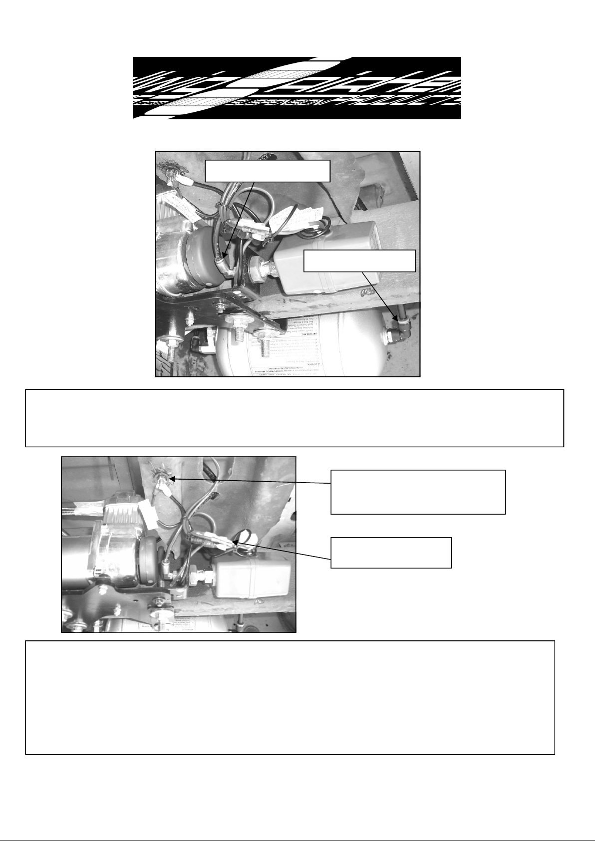
559-734-7451 800-367-5480 FAX 559-734-7460
Relay connection from tank
Tank connection to relay
24. Connect elbow fitting on relay bulkhead to 1/4” fitting on tank using 1/4” nylon tubing as
shown. Make sure hose will not be damaged by rubbing on any frame mounted components.
Use existing hole in crossmember to
ground compressor and relay. Remove
coating to provide ground contact.
Relay connections—see
next page for schematic.
25. Route 12 ga and 16 ga electrical wires from compressor to engine compartment along
driver’s side frame rail. Make sure to fasten wires securely to existing wire harness. Follow
plumbing and wiring diagram for connection of leveling valve, compressor, and relay. Take care
when routing air and electrical lines that they will not be crimped or chafed during installation or
use. Deviation from the electrical diagram and failure to use an inline fuse holder (supplied) will
void warranty. DO NOT install fuse in inline fuse holder until all connections and circuits are verified to be completed correctly.
6090 ( R-6090) 03/09/07
Page 19
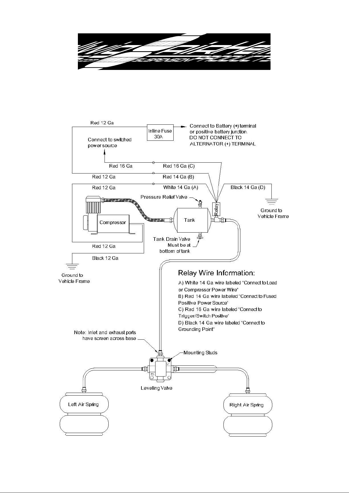
559-734-7451 800-367-5480 FAX 559-734-7460
Plumbing and Wiring Diagram
6090 ( R-6090) 03/09/07
Page 20
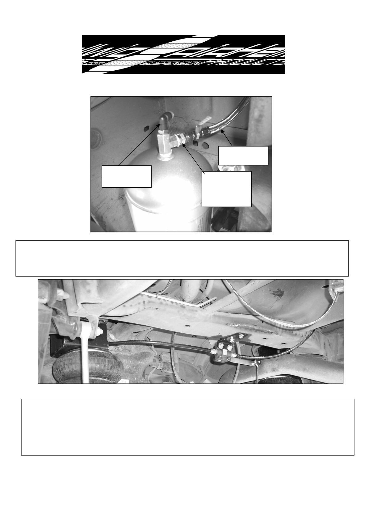
559-734-7451 800-367-5480 FAX 559-734-7460
Braided hose
from compressor.
Connect to inlet
of leveling valve.
Tighten this part
of fitting only to
avoid damaging
check valve
26. Connect compressor hose to tank fitting as shown above. Take care to tighten only the
specified fitting to avoid damaging check valve. Connect 3/8” tube elbow to inlet of leveling
valve with 3/8” nylon hose supplied. Route tubing to avoid chafing or damaging tubing.
27. Connect air springs to leveling valve as shown. Loop passenger side hose over crossmember as shown to avoid contact with exhaust pipe. Tie strap hoses as required to avoid contact
with exhaust and chafing on frame. (picture shown is for hose routing information only as vehicle shown has 6” lift installed.)
Page 21
559-734-7451 800-367-5480 FAX 559-734-7460
28. After all connections have been verified, install fuse in inline fuse holder, apply park
brake and start engine with shifter in park or neutral. Due to the amperage draw of the
compressor, failure to turn engine on during initial startup may drain the battery enough to
require a jump start.
29. Test system by adding air to air springs. Disconnect linkage from arm and rotate arm
up to fill air springs. Check all connections with soapy water for leaks. After the integrity of the system is verified, reconnect linkage to valve. A MINIMUM OF 5-10 PSI
MUST BE MAINTAINED IN AIR SPRINGS AFTER INSTALLATION FOR WARRANTY TO BE VALID. FAILURE TO KEEP MINIMUM PRESSURE IN AIR
SPRINGS WILL VOID WARRANTY.
30. Recheck all components and test drive vehicle. Re-check all components for mounting and proper torque. Check clearance to all vehicle components including suspension
components, exhaust pipe, brake lines, fuel lines, hoses, etc. Re-check installation on a
regular basis afterward. The air tank MUST be drained at least every couple of weeks to
prevent condenation buildup, FAILURE TO REGULARLY DRAIN AIR TANK WILL
VOID WARRANTY.
For Best Performance
This suspension system is designed to work with the factory supplied shocks and
suspension components, however, for increased performance, Hellwig Products recommends the following suspension upgrades:
Monroe Reflex Shock Absorber p/n 911178 front* / 911166 rear*
Hellwig p/n 7633 1-5/16” front sway bar
Hellwig p/n 7650 1-1/4” rear sway bar
*confirm part number to application as part number may change
6090 ( R-6090) 03/09/07
 Loading...