

559-734-7451 800-367-5480 FAX 559-734-7460
INSTALLATION INSTRUCTIONS
Thank you for purchasing a quality Hellwig Product.
PLEASE READ THISINSTRUCTION SHEETCOMPLETELY BEFORE STARTINGYOUR INSTALLATIONPROCEDURES.
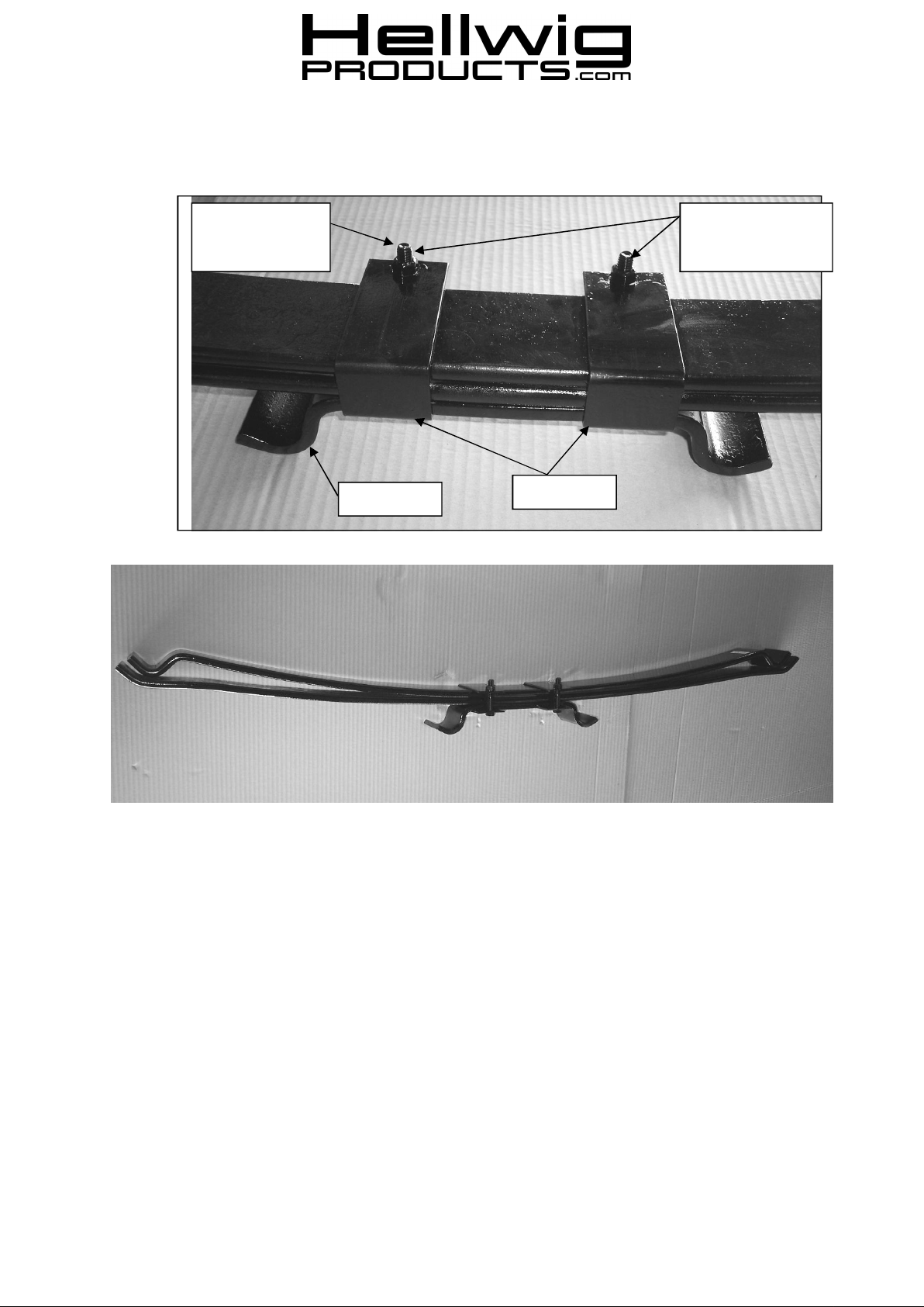
Bolts will point
inboard when installed on vehicle
Step Bracket
3/8 Bolt and Locknut
Leave Loose for Adjustment later
Retainer Clip
SAFETY: PARKYOUR VEHICLE ON A FLAT LEVEL SURFACE, SET THE PARKING AND CHOCK THE FRONT TIRES. IF
REAROF VEHICLEMUST BE RAISED,PLACE FRAME ON JACK STANDS BEFORE WORKING UNDER VEHICLE.
NOTE: THIS KIT INCLUDESLOCKNUTSWHICHREQUIRETIGHTENING WITH A WRENCH AFETRBEING STARTEDBY
HAND.
IMPORTANT NOTE: IF YOUR VEHICLE IS EQUIPEDWITH A FACTORY CONTACTOVER LOAD IT MUST BE REMOVED
BEFORE INSTALLINGTHE NEW HELPER SPRINGS.
IMPORTANT NOTE:HELLWIG HELPER SPRINGS ARE DESIGNEDTO INCREASE THE “LEVEL LOAD” CARRYING
CAPACITYOF YOUR VEHICLE.NEVER LOAD THE VEHICLE THAT THIS UNIT IS INSTALLEDON BEYOND THE
MANUFACTURER’S MAXIMUM GROSS VEHICLE WEIGHT RATING.
READ THIS INSTRUCTION SHEET COMPLETELY BEFORE STARTING YOUR INSTALLTION
9655 ( R-9655) 7/07/09
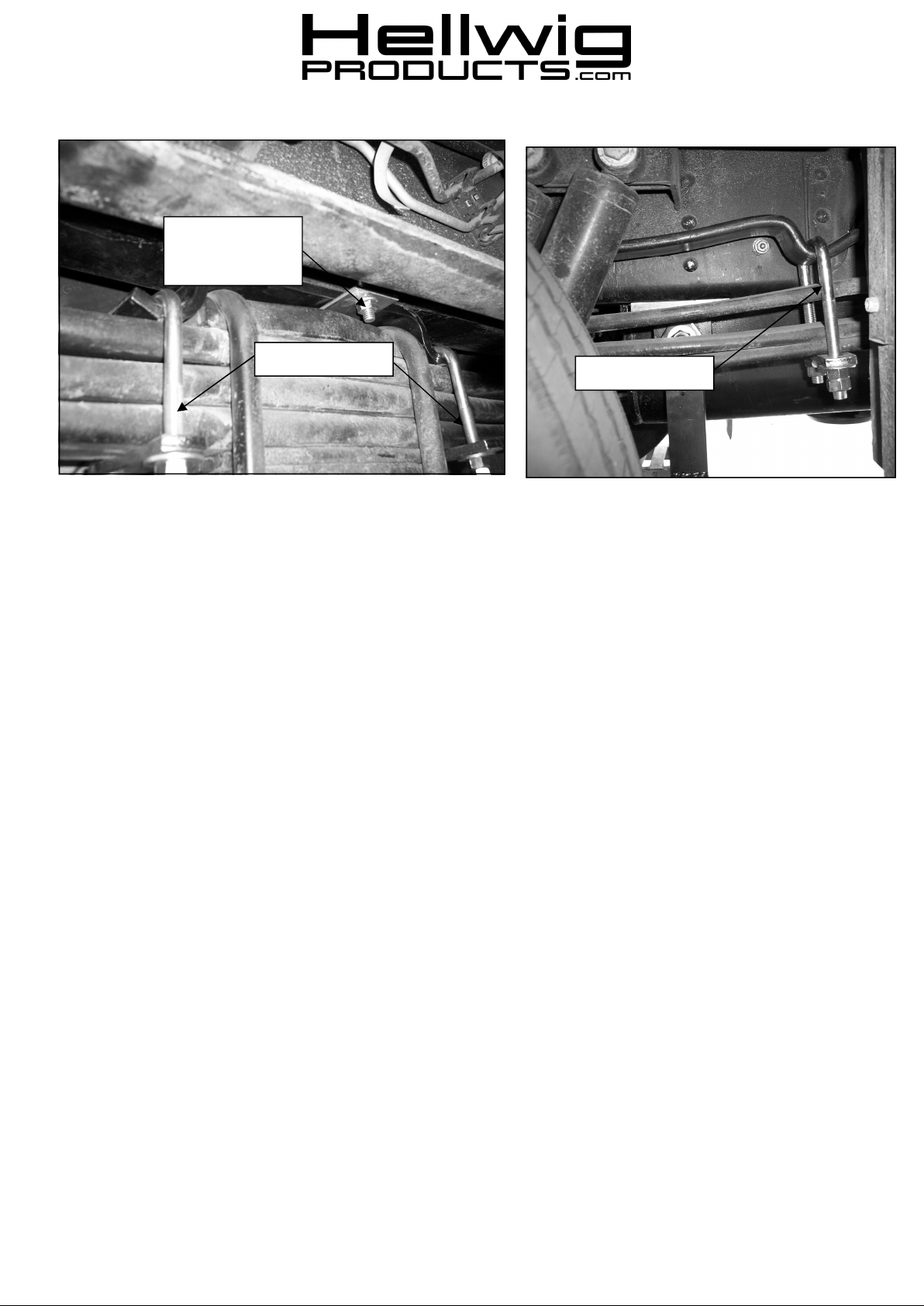
Bolts will point
inboard when installed on vehicle
559-734-7451 800-367-5480 FAX 559-734-7460
7/16” U-bolts
9/16” U-bolts
1. Set parking brake and chock front tires. The helper spring is designed to be installed without lifting vehicle.
If rear of vehicle must be raised, DO NOT work under the vehicle without placing the frame and axle on jack
stands first.
2. Remove rubber bump stops attached to frame abuve axle u-bolts.
3. Lay out the spring leaves into two (2) sets as shown in the photos.
4. Center and attach springs to step brackets with retainer straps as shown in photos. Install 3/8” bolt and
locknut in retainer clip but leave loose for adjustment later.
5. Install the spring assembly on top of the main spring with the bolts of the retainer clips pointing inboard.
6. Place the 7/16” U-bolts in the cups at the ends of the step bracket as shown. Loosely install the narrow
crossbars using the hardware provided.
7. Install the 9/16” U-bolts on the ends of the springs and adjust the crossbars so that the adjacent leaf tip will not
make contact with the crossbar when the spring is deflected. It may be necessary to move the spring stack fore
or aft in the retainer clips for best alignment.
8. Torque the nuts on the 7/16 U-Bolts to 40 ft-lb and double nut.
9. Adjust the U-bolts at the spring end to desired preload. The minimum tension adjustment is having enough
tension on the end U-bolts so that they do not loosen or rattle and move when the vehicle is driven over rough
or bumpy surfaces. Maximum adjustment is when the leaf cups have been deflected until there is 1/4” or the
thickness of a pencil between the leaf cup and the main spring. THE LEAF CUP MUST NOT TOUCH THE
MAIN SPRING AT THE ADJUSTMENT END.
10. When adjustment is complete, double nut to lock in adjustment.
11. Lower vehicle to the ground and check your installation for clearance on all undercarriage components; wires,
fuel, brake, and air conditioning lines. Test drive the vehicle and recheck your installation, adjust as needed.
Recheck on a monthly basis thereafter.
IMPORTANT NOTE: CHECK YOUR INSTALLATION. ARE ALL NUTS AND BOLTS SECURELY
TIGHTENED AND DOUBLE NUTTED WHERE PROVIDED? BOUNCE THE VEHICLE CHECKING
FOR CLEARANCE ON ALL UNDERCARRAIGE COMPONENTS, MUFFLERS, GAS FILLER PIPES,
BRAKE LINES, EMERGENCY BRAKE CABLE, AIR CONDITIONING LINES, RUBBER
BOTTOMING PADS, ETC.
9655 ( R-9655) 7/07/09
 Loading...