

Hellwig 7889 User Manual
559-734-7451 800-367-5480 FAX 559-734-7460
INSTALLATION INSTRUCTIONS
Rear Stabilizer Bar
2007 ToyotaTundra
Thank you for purchasing a quality Hellwig Product.
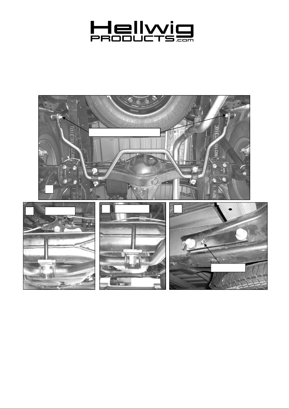
Attach end links to outermost hole
1
Passenger Side
2
SAFETY: BEFORESTARTINGYOUR INSTALLATION,BE SURE TO SET PARKING BRAKE AND CHOCK TIRES.
NOTE: TO EASE INSTALLATION AND TO PROPERLY ADJUSTBAR, THE WEIGHT OF THE VEHICLE MUSTBE ON THE SUSPEN
SION, AS IF DRIVING DOWN THE ROAD.DO NOT RAISE VEHICLEBY FRAME.
Driver Side
BOLT SIZE:3/8” = 20-30ft. lbs. – 7/16” = 35-45 ft. lbs. – ½” = 50-70 ft. lbs. – 9/16” = 70-90 ft. lbs.
3 4
Threaded Hole
TORQUE TABLE
NOTE: THIS KIT INCLUDES LOCK NUTS WHICH REQUIRE TIGHTENING WITH A WRENCH AFTER BEING STARTED BY HAND.
1. Place the U-bolts over the axle tubes as shown in photos 2 & 3. Be careful to place the U-bolts under any
brake lines or wires so not to damage them when the U-bolts are tightened.
2. Lubricate the D-shaped bushings and place them on the flat areas of the bar to line up with the U-bolts. Place
the U-plates over the D bushings.
7692 (R-7692) 08/22/2007
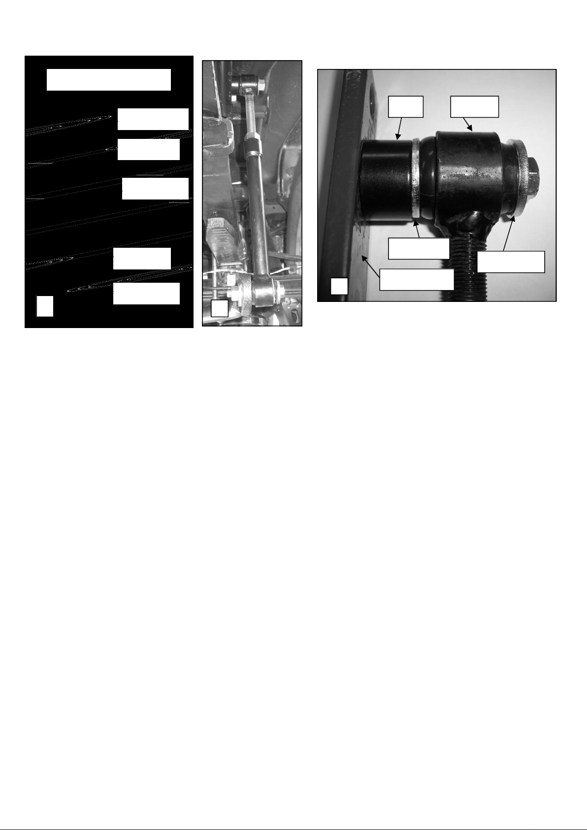
End LinkAssembly
Spacer End Link
Bushing
Sleeve
9/16-18 Nut
Thin Washer
Sleeve
Mounting Plate
Bushing
5
3. Place the spring steel plates onto the U-bolts so that they lie flat against the bottom of the axle.
4. Raise the bar up to the u-bolts and mount the bushings and U-plates to the U-bolts with 1/2” washers and nuts.
Leave loose at this time. Mount sway bar so that the center hump is parallel with the ground and the arms angle
upward to attach to the end links.
5. Remove trailer hitch bolts and install mounting plate with threaded hole toward front of vehicle as shown in
photo 4. Reinstall bolts and torque to 70 ft-lb. If vehicle does not have a trailer hitch, p/n 7699 mounting kit
will be required. Locate threaded holes in frame in the area shown in photo 4 to attach mounting plate. Attach
mounting plate using M14-1.5 X 50mm bolts and washers supplied in kit. Torque bolts to 70 ft-lb.
6. Assemble end link assembly by inserting hourglass bushings into loops in end links first. Then insert sleeves
into bushings. Lubricate bushings and sleeves with supplied grease before assembly. Assemble end links as
shown in detail #5 above.
IMPORTANT NOTE: The end link threads are NOT powder coated so that the end links can be
threaded together. To prevent corrosion, it is advised to lightly coat the exposed threads with black
spray paint after adjusting to desired length.
7. Attach end link to mounting plate using 7/16 X 2-3/4 bolt, washers and spacer as shown in photos 6 & 7. Note
orientation of washers and spacer when attaching end link to mounting plate. Torque bolt to mounting plate to
35-40 ft-lb.
8. Attach end link to outermost hole in sway bar using 7/16 X 2-3/4 bolt, thick washers and locknut as shown in
photos 1 & 6. Torque bolt to 40 ft-lb and tighten large nut on end links to lock adjustment.
9. With the bar properly aligned, verify that all vehicle components have proper amount of clearance, and that
brake lines, wires, cables, and other components will not be pinched or crushed when u-bolts are tightened.
Torque U-bolts to 50ft-lb. Double nut the axle U-bolts.
10. Bounce the vehicle checking for clearance on all under carriage components – exhaust, shocks, differential, etc.
Test drive the vehicle and recheck all clearances and the installation alignment. Adjust as needed. Recheck
your installation after one week of driving and periodically on a regular basis.
11. The sway bar arms have three mounting holes. Mounting the sway bar on the outer hole is the nominal position.
For firmer settings, use the inner holes. We recommend starting with the outer mounting hole as in photo ( 2 )
until you are accustomed to the vehicles new handling characteristics. Select the mounting point that best fits
your driving style.
6
7
Thick Washer
ATTENTION INSTALLER: PLEASE MAKE SURE CUSTOMER RECEIVES THIS INSTRUCTION SHEET,
ALL IMPORTANT NOTE CARDS, WARNING CARDS AND THE WARRANTY
FORM
7692 (R-7692) 08/22/2007
 Loading...