

559-734-7451 800-367-5480 FAX 559-734-7460
INSTALLATION INSTRUCTIONS
1997-2006 Jeep Wrangler TJ
(Coil Sprung Front Suspension)
7870 FRONT STABILIZER BAR
Thank you for purchasing a quality Hellwig Product.
PLEASE READ THIS INSTRUCTION SHEET COMPLETELY BEFORE STARTING YOUR INSTALLATION
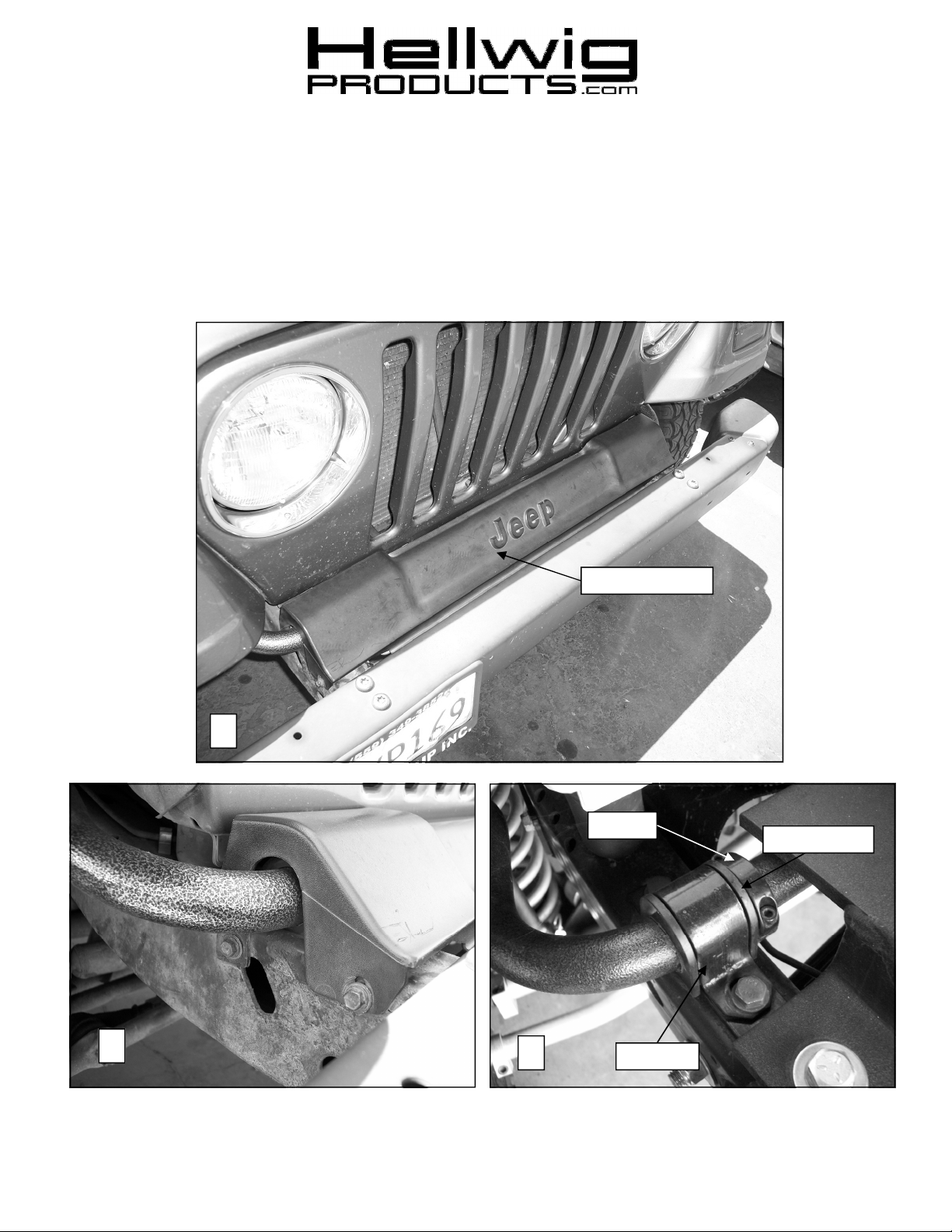
1
Plastic Cover
Collar
D Bushing
2
7870 ( R-7870 ) 8/3/2011
3
U-Plate
559-734-7451 800-367-5480 FAX 559-734-7460
SAFETY:
NOTE:
ON THE SUSPENSION, AS IF DRIVING DOWN THE ROAD.
NOTE:
BEFORE STARTING YOUR INSTALLATION, BE SURE TO SET PARKING BRAKE AND CHOCK TIRES.
TO EASE INSTALLATION AND TO PROPERLY ADJUST THE BAR, THE WEIGHT OF THE VEHICLE MUST BE
NOTE:
THIS KIT INCLUDES LOCK NUTS WHICH REQUIRES TIGHTENING WITH A WRENCH AFTER BEING
BOLT SIZE: 3/8” = 20-30 ft. lbs. – 7/16” = 35-45 ft. lbs. – 1/2” = 50-70 ft. lbs. – 9/16” = 70-90 ft. lbs.-5/8”=120 ft. lbs.
THIS SWAY BAR IS DESIGNED TO MOUNT ON THE TOP OF THE WITH
THE ARMS TOWARDS THE BACK OF THE VEHICLE.
STARTED BY HAND.
TORQUE TABLE
DO NOT RAISE VEHICLE BY THE FRAME.
1. Remove the front factory sway bar by unbolting the plastic cover piece on the bumper, unbolting the uplates behind the bumper on the top of the frame and disconnecting the end links from the axle as shown in
Photos 1, 2 and 3. Save the u-plate bolts as they will be reused.
2. Remove end link bolt from axle brackets by turning the bolt until it breaks free. Penetrating fluid may be
necessary if the bolt is rusty. The new end link pin will occupy the mounting hole in the axle brackets.
3. Lubricate the inside of the D shaped bushing and place them on the sway bar in the stock location.
4. Place the bar over the frame, center it and then bolt the u-plate over the D bushing to hold the bar in place.
Leave loose at this time for later adjustment.
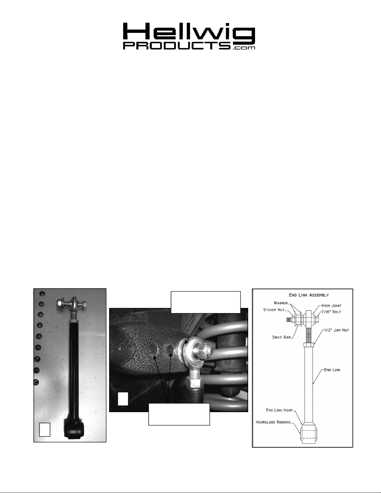
5. Assemble end links together as shown in photo 4 and the diagram. The heim joint will be threaded into the
end link with a jam nut. Lubricate the outside of the hourglass bushing and tap it into the hoop on the end
link. Leave loose at this time for later adjustment. Protective rubber boots (included in kit) can be installed on the rod ends prior to assembly to increase durability of the assembly.
Outermost Hole for
Initial Driving
5
Inner Holes for
Stiffer Handling
4
7870 ( R-7870 ) 8/3/2011
559-734-7451 800-367-5480 FAX 559-734-7460
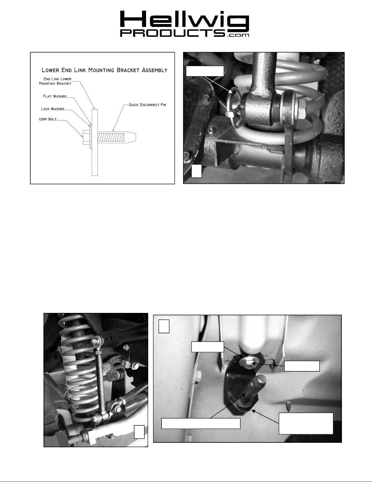
Linch Pin
6
6. Loosely attach the rod end to the middle hole on the sway using the 7/16” bolt, washers and stover nut.
The middle hole position is for sizing the end link only, it is recommended to start with the end link
attached to the outermost (softest) hole until the driver gets used to the change in ride characteristic and
they can then adjust the hole positioning for their driving style.
7. Attach the quick disconnect pins to the existing lower end link mounting bracket following the diagram
and Photo 6. Torque bolts to 25-30 ft-lb. A small phillips screwdriver can be inserted in to the hole in
the end of the pin to keep it from turning while tightening bolt.
8. Lubricate the inside of the hourglass bushing on the end link and slide it over the quick disconnect pin.
This will be held in place with the included linch pin.
9. Lengthen or shorten the end link so the sway bar arms are parallel to the ground. Once it’s the correct
length, tighten the jam nut to hold it in place.
10. Move the rod end to the outermost hole, recheck that the bar is centered and tighten down all end link
bolts to 35-40 ft lb and u-plate bolts in frame to 25 ft-lb.
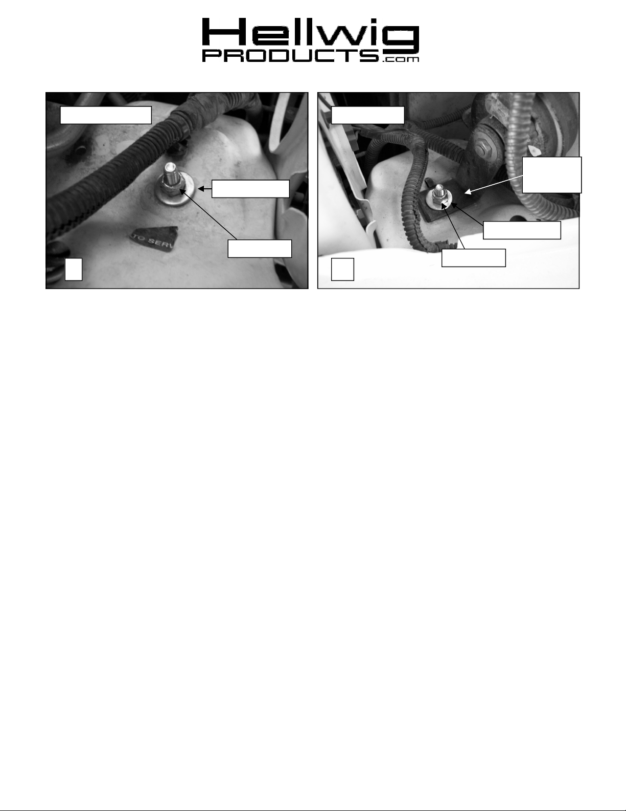
8
Washer
3/8” Bolt
Quick Disconnect Pin
End Link
Fender Bracket
7
7870 ( R-7870 ) 8/3/2011
559-734-7451 800-367-5480 FAX 559-734-7460
Passenger Side
Driver Side
Existing
Bracket
Flat Washer
Stover Nut
9
Flat Washer
Stover Nut
10
11. On the inside of each D Bushing, place the collar to prevent lateral movement and tighten the allen head
screws to 7-8 ft-lbs. See Photo 3.
12. Replace the plastic cover over frame bushings.
13. Connect the end link quick disconnect pins to the fender mounting brackets as shown in photo 8. The end
links can be disconnected from the axle and moved to these locations when the vehicle is being used offroad and needs additional suspension flex. For onroad use, leave the end link attached to the lower end
link mounting bracket.
14. On the passenger side, using the existing hole on the top of the fender, bolt the end link fender tab to the
underside of the fender. The hole may need to be widened for the 3/8” bolt. See Photos 8 and 9.
15. On the driver side, remove the screw holding the horn mounting bracket to the top of the fender. Replace
this with the included 3/8” bolt to hold the end link fender tab and the bracket in place. The hole may
need to be widened for the 3/8” bolt. See Photos 8 and 10.
16. Bounce the vehicle, check for clearance on all undercarriage components; exhaust, wires, shocks, brake
and fuel lines. Test drive the vehicle and recheck for clearance and installation alignment.
17. For off highway use, the end links can be disconnected from the axle and moved to the pins on the fender
mounting brackets to allow additional suspension flex. For onroad use, make sure the end links are attached to the pins attached to the axle mounting brackets.
18. After one week of driving recheck your installation recheck on a regular basis thereafter.
ATTENTION INSTALLER:
ALL IMORTANT NOTE CARDS AND THE WARRANTY FORM
BE SURE THAT THE CUSTOMER RECEIVES THIS INSTRUCTION SHEET,
7870 ( R-7870 ) 8/3/2011
 Loading...