

INSTALLATION INSTRUCTIONS
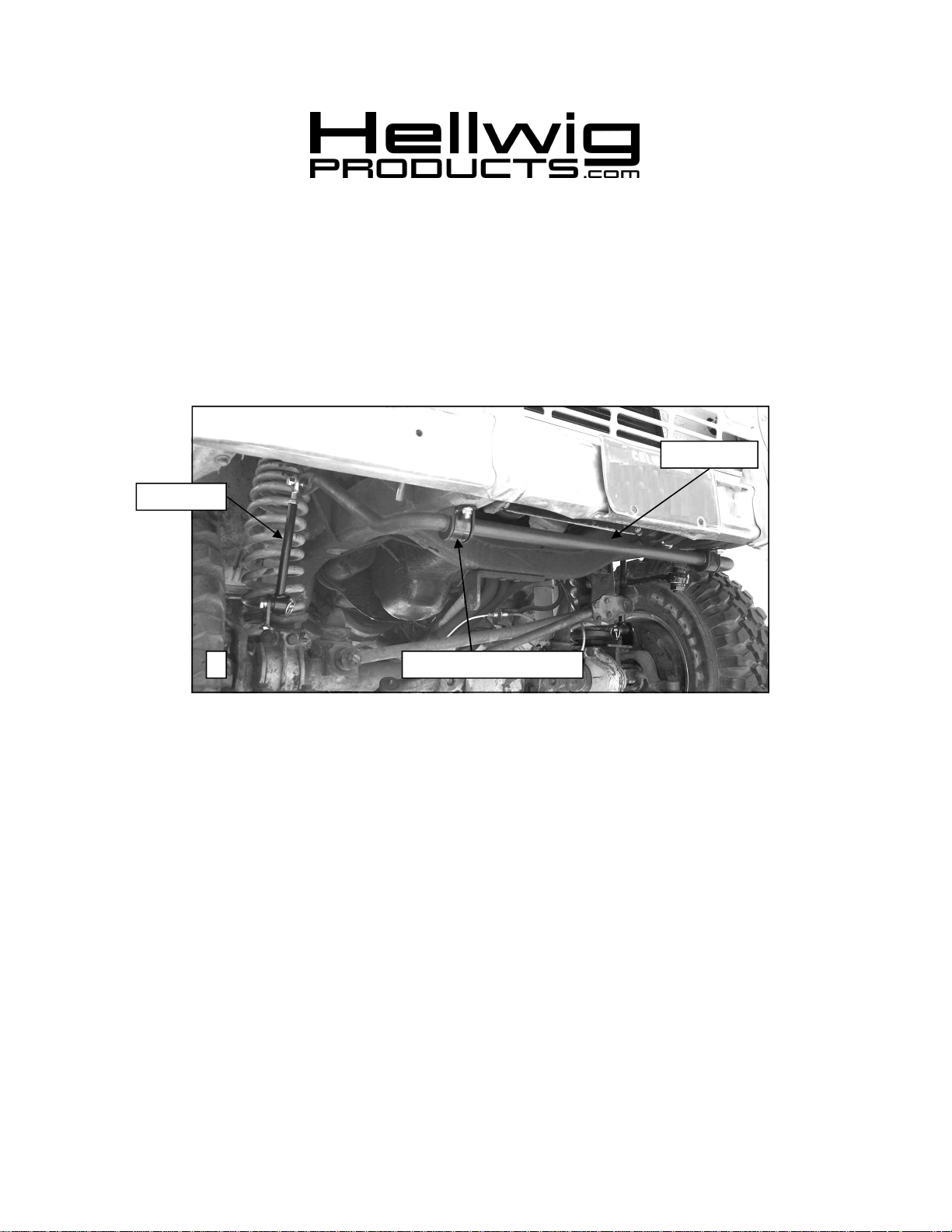
End Link
559-734-7451 800-367-5480 FAX 559-734-7460
Front Stabilizer Bar 7868
1966-77 Ford Bronco
Thank you for purchasing a quality Hellwig Product.
Sway Bar
1
TORQUE TABLE
Bolt Size 3/8”— 35 ft lbs * Bolt Size 7/16”— 45 ft lbs* Bolt Size 1/2”—75 ft lbs *Bolt Size 9/16”—
90 ft lbs
SAFETY: BEFOREBEGINNING INSTALLATION BE SURE TO SET THE PARKING BRAKE
AND CHOCK THE WHEELS.
NOTE: TO EASE INSTALLATION AND PROPERLY ADJUST THE BAR, THE WEIGHT OF
THE VEHICLE MUST BE ON THE SUSPENSION AS IF DRIVING DOWN THE ROAD. DO NOT
RAISE THE VEHICLE BY THE FRAME (Other than to remove the coil spring).
NOTE: THIS KIT REQUIRES DRILLING THE FRAME RAIL AND POSSIBLE
RELOCATION OF FUEL AND BRAKE LINES. INSTALLER MUST ENSURE
THAT THE SWAY BAR KIT WILL NOT INTERFERE WITH ANY FUEL OR
BRAKE LINES OR HOSES.
U-Plate and Bushing
7868 (R-7868) 07/13/2011
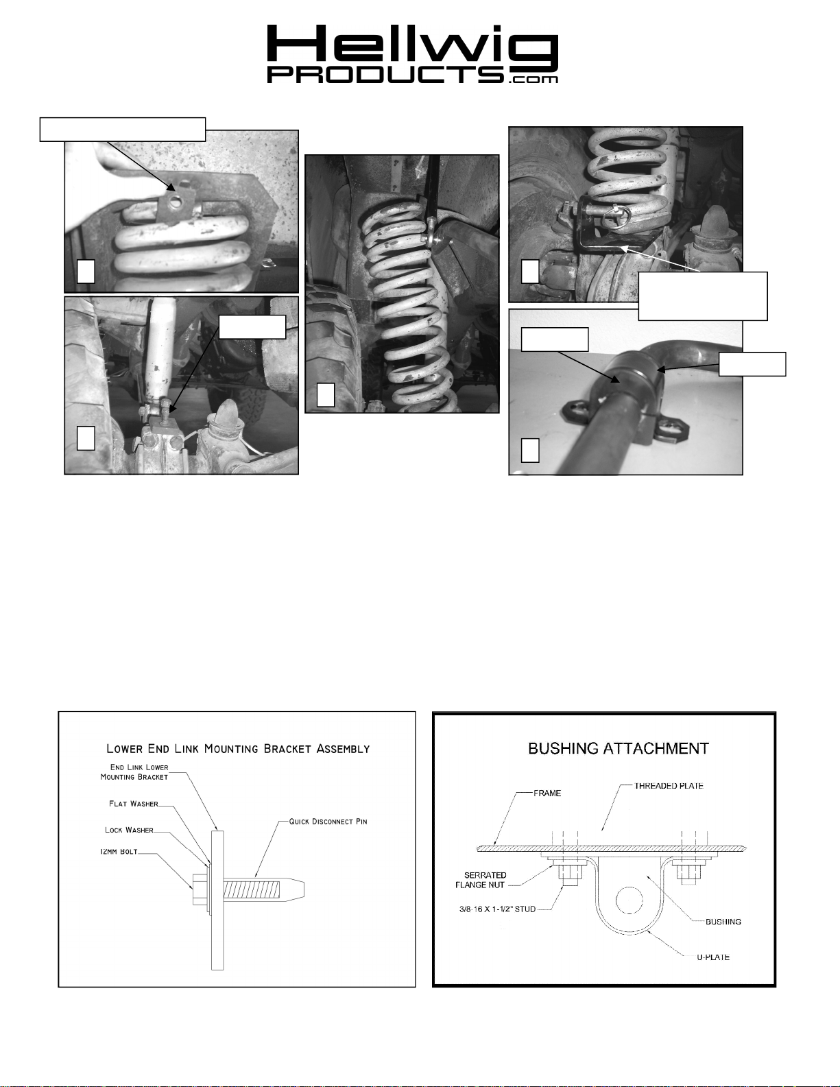
Upper Retaining Clip
559-734-7451 800-367-5480 FAX 559-734-7460
2 5
Lower End Link
Mounting Plate
Bolts
Bushing
U-Plate
3
4
6
1. With the vehicle sitting on the ground, remove the upper retaining clip from your coil spring by removing the two bolts. See
PHOTO 2.
2. Jack the vehicle up by the frame until the wheel is at full droop, support the frame with jack stands, pry the top of the coil
out of the upper coil bucket. See PHOTO 3.
3. Remove the two bolts through the lower retaining plate to the radius arm from the center of the spring. Remove the entire
coil from the vehicle. See PHOTO 4.
4. Assemble the lower end link mounting bracket by bolting the end link quick disconnect pin to the end link plate using the
12mm bolt and both the flat and lock washer according to the diagram below.
5. Place the lower end link plate on the top of the radius arm as shown in PHOTO 5 with end link tab outboard. Line up the
two holes. Reattach the coil following the previous instructions in reverse with the lower end link mounting plate sandwiched
between the coil bucket and the torsion bar. We have included longer radius arm bolts and washers to compensate for the
additional width of the mounting plate. See PHOTO 5.
6. Remove the jack stands and lower the vehicle back on its on weight and then repeat the previous steps to install the lower
7868 (R-7868) 07/13/2011

559-734-7451 800-367-5480 FAX 559-734-7460
Drilled
Hole
Existing
Hole
2.68”
Front of Vehicle
7
7. Lubricate the inside diameter of the D-Bushings and place them onto the straight area of the bar as shown in PHOTO 6. Install U-plates on D-bushings.
8. On the underside of the frame towards the bumper, mark holes for U-Plates. The hole will be approximately 2.68” forward
of the center of the oval hole already in the frame. Use threaded plate as a guide for hole spacing. Check clearance of
threaded plate to inner frame before drilling holes.
9. Drill a 7/16” hole on both frame rails. See PHOTO 7.
10. Attach U-plates to frame rail with 3/8-16 X 1” studs and serrated flange nuts as shown in the diagram on Page 2. Leave
loose for adjustment later. See PHOTOS 8 & 9.
11. Fully lubricate bushings before installation. Press hourglass bushing into end link loop. Install 7/16” nut on threaded section of heim joint before assembling the two halves together as shown in PHOTO 10.
12. Attach end links to the center hole of the sway bar as shown in PHOTO 11 and change end link length so the three end link
holes are parallel to the ground. IMPORTANT NOTE – Center hole position is only for determining hole location. The
end link will be moved to the outer hole prior to initial use.
13. Lubricate the inside of the hourglass bushing and slide it over the quick disconnect pin. Insert the linch pin to keep the end
link from sliding off. See PHOTO 12. It will make disconnecting the end link easier if this bushing is regularly lubricated.
14. Align sway bar and end links and tighten 3/8” mounting bolts to 25 ft-lb. The bar should be offset to the driver side as far as
the bushings allow to maximize clearance between the sway bar and the steering box/pitman arm.
15. Place collar clamps on sway bar inside of the D bushings on the bar to keep the sway bar aligned during use. Torque bolts
on collar clamps to 5-8 ft-lb..
8 9
3/8” Stud
10 11 12
7868 (R-7868) 07/13/2011

559-734-7451 800-367-5480 FAX 559-734-7460
Flat Washer
Stover Nut
13
15. Disconnect the end link from the quick disconnect pin and rotate the bar and end link so the end link is against the inside wheel
well. See PHOTO 13.
16. Connect the end link quick disconnect pins to the end link fender tab in the same manner used for the end link lower mounting
bracket.
17. Align tab for best fit and mark where to drill the hole. BEFORE DRILLING, DISCONNECTBATTERYAND VERIFY
THAT DRILL WILL NOT CONTACT OR DAMAGE ANY BRAKE, FUEL, COOLANT LINES,BATTERY, ELECTRICAL COMPONENETS, WIRING, OR ANY OTHER ENGINE COMPARTMENT COMPONENTS.
18. Drill a 5/16” (.3125”) hole and bolt the end link fender tab to the inner fender. See PHOTOS 14, 15 & 16. The end links can be
disconnected from the axle and moved to these locations when the vehicle is being used offroad and needs additional suspension flex. For onroad use, leave the end link attached to the lower end link mounting bracket.
19. With the end link attached to the end link fender tab as well as the axle, bounce the vehicle checking for clearance on all
under carriage components: fuel tank, shocks, differential, brake and fuel lines, etc. Test drive the vehicle and recheck all
clearances and the installation alignment. Adjust as needed. Re-check your installation after one week of driving and periodically on a regular basis.
20. The sway bars arms have three mounting holes. Mounting the sway bar on the outer hole (rear-most) is the nominal
position. For a firmer setting, use the inner holes. We recommend starting with the outer mountinghole until you are
accustomed to the vehicles new handling characteristics. Select the mounting point that best fits your driving style.
14
15
ATTENTION INSTALLER: BE SURE THAT THE CUSTOMER RECEIVES THIS INSTRUCTION
SHEET, ALL IMORTANT NOTE CARDS AND THE WARRANTY FORM
Flat Washer
3/8” Bolt
Quick Disconnect Pin
16
7868 (R-7868) 07/13/2011
 Loading...