

Hellwig 7852 User Manual
559-734-7451 800-367-5480 FAX 559-734-7460
INSTALLATION INSTRUCTIONS
REAR STABILIZER BAR
84-87 C/K 10-20
Thank you for purchasinga quality Hellwig Product.
PLEASE READ THIS INSTRUCTION SHEETCOMPLETELY BEFORE STARTINGYOUR INSTALLATION
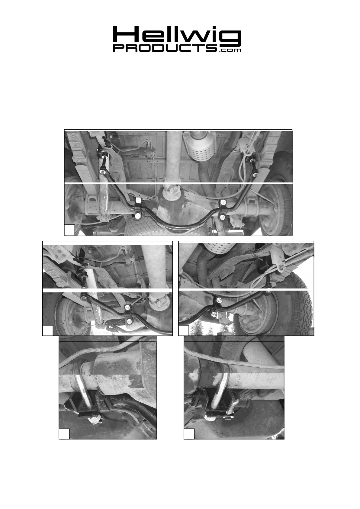
1
2 3
4 5
( R-238) 06/17/04

559-734-7451 800-367-5480 FAX 559-734-7460
TORQUETABLE
BOLT SIZE: 3/8” = 20-30 ft. lbs. – 7/16” = 35-45 ft. lbs. – ½” = 50-70 ft. lbs. – 9/16” = 70-90 ft. lbs.
SAFETY: BEFORE STARTING YOUR INSTALLATION, BE SURE TO SET PARKINGBRAKE AND CHOCK TIRES.
NOTE: TO EASE INSTALLATION AND TO PROPERLY ADJUST THE BAR, THE WEIGHT OF THE VEHICLE MUST BE
ON THE SUSPENSION, AS IF DRIVING DOWN THE ROAD. DO NOT RAISE VEHICLE BY THE FRAME.
NOTE: THIS SWAY BAR IS DESIGNED TO MOUNT BELOW THE AXLE TUBES WITH THE ARMS OF THE SWAY BAR
FAGING TOWARDS THE FRONT OF THE VEHICLE.
NOTE: IN SOME APPLICATIONS IT MAY BE NECESSARY TO REVERSE THE MOUNTING OF THE SWAY BAR TO
ALLOW FOR THE BEST FIT FOR YOUR PARTICULAR VEHICLE.
NOTE: THIS KIT INCLUDES LOCK NUTS WHICH REQUIRE TIGHTENING WITH A WRENCH AFTER BEING STARTED
BY HAND.
1. Install the D-shaped poly bushings on the sway bar between the center hump and the arms of the sway bar.
2. Position the sway bar on the rear axle . SEE PHOTO ONE (1).
3. Install the U-bolts over the axle tubes with the legs pointing towards the front of the vehicle. Position the
saddle brackets over the legs of the U-bolts. The saddle brackets will be in front of the rear axle. Position the
sway bar on the rear axle align the D-bushings to match the U-bolts and saddle brackets on the axle assy. Install the U-plates over the D-bushings and fasten with mounting hardware provided. Leave loose at this
time to allow for adjustment later. ( Make sure that the U-bolts are under the brake lines on the axle). SEE
PHOTOS FOUR (4) AND FIVE (5).
4. Locate the hole on the trucks frame just behind the forward spring hanger on both sides. SEE PHOTO TWO
(2) AND THREE (3). Install the angle frame brackets using the (1/2” x 1-1/2”) cap screw and mounting
hardware provided. Assemble the end link assemblies and attach to the brackets attached to the frame.
Tighten until the bushings begin to bulge slightly. Do not over tighten our damage will result to the end
link bushings.
5. Raise the sway bar arms up to the end links and finish assembling the end links. Rotate the sway bar on the
axle to be centered and level with the ground and so the end links are straight up and down as possible. There
should be no less than (1/4”) clearance on the differential housing and the hump of the sway bar.
6. Once the sway bar has been centered and the end links are straight up and down as possible torque all the
mounting hardware to the specified rate.
7. Bounce the vehicle checking for clearance on all under carriage components. Be sure all nuts and bolts are
securely tightened and double nuts are used where provided.
8. Recheck your installation, look for clearance on wiring, exhaust, fuel and brake lines etc.. After one week of
driving recheck your installation readjust if necessary. Recheck on a monthly regular basis thereafter.
ATTENTION INSTALLER: BE SURE THAT THE CUSTOMER RECEIVES THIS INSTRUCTIONSHEET, ALL IMORTANT NOTE
CARDSAND THE WARRANTY FORM .
( R-238) 06/17/04
 Loading...