

559-734-7451 800-367-5480 FAX 559-734-7460
INSTALLATION INSTRUCTIONS
Thank you for purchasing a quality Hellwig Product.
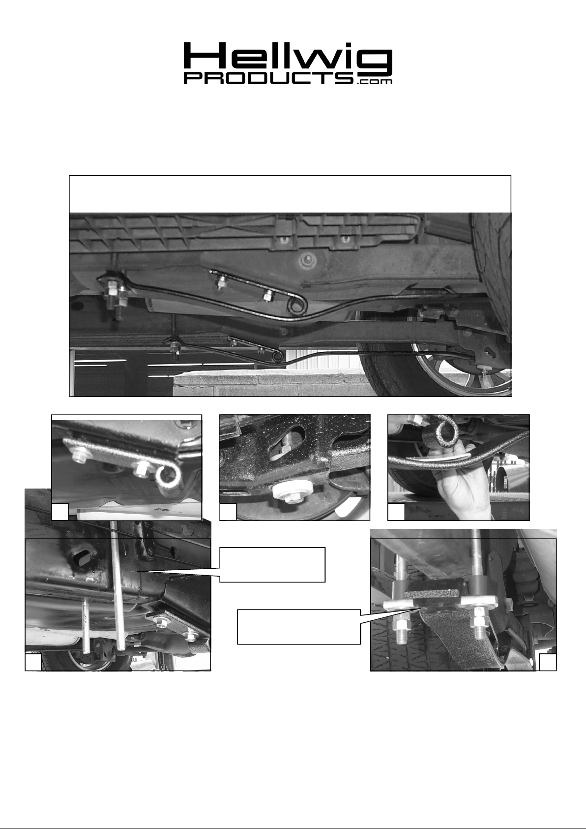
1 2 3
EMERGENCY BRAKE
CABLE
POLYURETHANE
CROSSBAR INSULATOR
( R-1901 ) 09/14/04
54

559-734-7451 800-367-5480 FAX 559-734-7460
TORQUE TABLE
BOLT SIZE: 3/8” = 20-30 ft. lbs. – 7/16” = 35-45 ft. lbs. – ½” = 50-70 ft. lbs. – 9/16” = 70-90 ft. lbs.
IMPORTANT: PLEASE READ THIS INSTRUCTION SHEET COMPLETELY BEFORE STARTING YOUR
INSTALLATION.
SAFETY: PARK YOUR VEHICLE ON A FLAT LEVEL SURFACE, SET THE PARKING AND CHOCK THE
FRONT TIRES.
IMPORTANT NOTE: HELLWIG HELPER SPRINGS ARE DESIGNED TO INCREASE THE LOAD LEVEL
CARRYING CAPACITY OF YOUR VEHICLE. NEVER LOAD THE VEHICLE THIS
UNIT IS BEENING INSTALLED ON BEYOND THE MANUFACTURERS MAXIMUM
GROSS VEHICLE WEIGHNOTE: THIS KIT INCLUDESLOCK NUTS WHICH REQUIRE
NOTE: THIS KIT INCLUDES LOCK NUTS WHICH REQUIRE TIGHTENING WITH A WRENCH AFTER
BEING STARTED BY HAND.
1. Install the eye plates using the 1/2” x 1-1/4” cap screws, flat washers and lock nuts provided in this
kit. SEE PHOTO ONE (1).
2. Install the plastic insulator pads on the diagonal cut ends of the leaf spring with the hole. Place one
pad between the leaf and mounting point under the axle. Install one washer and plastic insulator pad
on the 1/2” x 2-1/2”bolt provided and install thru the hole in bottom of the mounting point. Mounting
will be as follows bolt, washer, insulator pad, mounting point, insulator pad, leaf spring, insulator
pad, washer and lock nut. ( SEE PHOTO (2). Leave loose at this time to allow for adjustment
later.
3. With the end loosely attached at the mounting point under the axle. Lift the other end of the spring
until contact is made with the eye plate. Visually make note and mark the contact area. This area is
where the friction pad will be placed on the leaf spring. Install by applying the adhesive side of the
friction pad to the top of the leaf spring. SEE PHOTO THREE (3).
4. Approximately 12” forward of the front mounting bolt on the lower trailing arm. Slide the 9” U-bolts
provided over the frame with the legs pointing to the ground. Be sure the U-bolt is under any wires
or lines routed along the top side of the frame rail, and between the frame rail and emergency
brake cable. SEE PHOTO FOUR (4).
5. After proper location for the U-bolts has been determined. Slide the polyurethane insulator over the
crossbar. Install the crossbar on the U-bolt so that the raised part of the insulator will fit into the
U-bolt saddle of the leaf spring. Tighten evenly with the flat washers and double nut. Tighten the Ubolts until there is approximately 3/4” of clearance between the bottom of the frame and the top of
the U-bolt saddle of the leaf spring. Do not overtighten beyond this point. SEE PHOTO FIVE (5).
6. Tighten all hardware to the specified torque rate. Bounce the vehicle and check for clearance on all
under carriage components.
7. After one week of driving recheck your installation, re-torque as necessary. Recheck your installation
on a monthly regular basis thereafter.
ATTENTION INSTALLER: BE SURE THE CUSTOMER RECEIVES THIS INSTRUCTION SHEET,
ALL IMPORTANTNOTE CARDS, WARNING CARDS, AND THE
WARRANTY FORM.
( R-1901 ) 09/14/04

559-734-7451 800-367-5480 FAX 559-734-7460
PARTS LIST
KIT # 1901
COIL SPRING HELPER
1500 SUBURBAN, TAHOE, YUKON, ESCALADE, DENALI & AVALANCHE
PART # QTY DESCRIPTION
21101901 1 RIGHT HAMMERTONE SPRING LEAF
21101902 1 LEFT HAMMERTONE SPRING LEAF
21801901 2 EYE PLATE HAMMERTONE
118001901 2 1/2” X 3-1/8” X 9” SQUARE U-BOLT
112070233 2 CROSSBAR
125001901 1 SMALL PARTS BAG # BG-1901
101500307 4 1/2” X 1-1/4” N.F. CAP SCREW
101500188 2 1/2” X 2-1/2” N.F. CAP SCREW
105521044 8 1/2" N.F. HEX NUT
107521044 6 1/2" N.F. LOCK NUT
102520043 12 1/2” FLAT WASHER
20800901 2 2” LONG UHMW TAPE STRIP
20800190 4 1” LONG 1/2” U-BOLT COLLAR
20800175 6 1/2" UHMW SPACER
111000901 2 3” LONG CROSSBAR INSULATOR
135001901 1 INSTRUCTION SHEET #1901
( R-1901 ) 09/14/04
 Loading...