

559-734-7451 800-367-5480 FAX 559-734-7460
INSTALLATION INSTRUCTIONS
Thank you for purchasing a quality Hellwig Product.
PLEASE READ THISINSTRUCTION SHEETCOMPLETELY BEFORE STARTINGYOUR INSTALLATIONPROCEDURES.
TORQUE TABLE
BOLT SIZE: 3/8” = 20-30 ft. lbs. – 7/16” = 35-45 ft. lbs. – ½” = 50-70 ft. lbs. – 9/16” = 70-90ft. lbs
SAFETY: PARKYOUR VEHICLE ON A FLAT LEVEL SURFACE, SET THE PARKING AND CHOCK THE FRONT TIRES.
NOTE: THIS KIT INCLUDESLOCKNUTSWHICHREQUIRETIGHTENING WITH A WRENCH AFETRBEING STARTEDBY
HAND.
NOTE: IF YOUR VEHICLEIS EQUIPPED WITH A BRAKE FLUIDPROPORTIONING VALVEON THE REAR AXLE READ
INSERT(R-362)
IMPORTANT NOTE: IF YOUR VEHICLE IS EQUIPEDWITH A FACTORY CONTACTOVER LOAD IT MUST BE REMOVED
BEFORE INSTALLINGTHE NEW HELPER SPRINGS.
IMPORTANT NOTE:HELLWIG HELPER SPRINGS ARE DESIGNEDTO INCREASE THE “LEVEL LOAD” CARRYING
CAPACITYOF YOUR VEHICLE.NEVER LOAD THE VEHICLE THAT THIS UNIT IS INSTALLEDON BEYOND THE
MANUFACTURER’S MAXIMUM GROSS VEHICLE WEIGHT RATING.
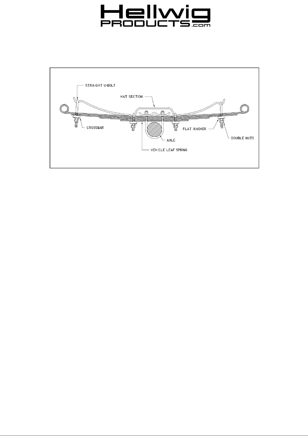
1. Lay out the spring leaves into two (2) sets. The long end of the spring must be installed toward the rear of the
vehicle and the short end toward the front.
2. Place the spring on top of the main spring with the long end toward the rear of the vehicle.
3. Place the U-bolts with the straight legs in the cups at the ends of the spring with the silencer bushing between
the main spring and the helper spring as shown in the diagram. Loosely install the crossbars using the
hardware provided.
4. Adjust the crossbars on the end of the springs so that the adjacent leaf tip will not make contact with the
crossbar when the spring is deflected. It may be necessary to move the spring stack fore or aft for best
alignment.
5. Install 1/2”U-bolts next to the hat section as shown in the diagram. The U-bolt should be fastened as close to
the hat section as possible. If you are working on 2-1/2” wide springs position the outboard U-bolt leg against
the outboard edge of the main spring to maximize brake hose, caliper, and backing plate clearance. The Ubolts may also be installed with the legs pointing up and crossbars on top of spring to provide additional
clearance. Install the wide crossbar with the washers and nuts supplied. Torque the nuts to 50-60 ft-lb and
double nut.
READ OPPOSITE SIDE COMPLETELY
014 ( R-014) 09/16/2010

559-734-7451 800-367-5480 FAX 559-734-7460
7. Adjust the U-bolts at the spring end to desired preload. The minimum tension adjustment is having enough tension on the end U-bolts so that they do not loosen or rattle and move when the vehicle is driven over rough or
bumpy surfaces. Maximum adjustment is when the leaf cups are 1/4” from the main spring.
8. When adjustment is complete, double nut to lock in adjustment.
9. Lower vehicle to the ground and check your installation for clearance on all undercarriage components; wires,
fuel, brake, and air conditioning lines. Test drive the vehicle and recheck your installation, adjust as needed.
Recheck on a monthly basis thereafter.
IMPORTANT NOTE: CHECK YOUR INSTALLATION. ARE ALL NUTS AND BOLTS SECURELY
TIGHTENED AND DOUBLE NUTTED WHERE PROVIDED? BOUNCE THE VEHICLE CHECKING
FOR CLEARANCE ON ALL UNDERCARRAIGE COMPONENTS, MUFFLERS, GAS FILLER PIPES,
BRAKE LINES, EMERGENCY BRAKE CABLE, AIR CONDITIONING LINES, RUBBER BOTTOMING
PADS, ETC.
IMPORTANT NOTES, WARNINGSAND TIPS
Before attempting the installation of any Hellwig Accessory Spring , be sure and identify the vehicle to which the
accessory spring will be installed as either being or not being equipped with height sensing brake fluid proportioning
valve. If a vehicle is equipped with the brake fluid proportioning valve on the rear axle, it is recommended that any
Hellwig Full Time Accessory Spring NOT be installed. Only the Progressive Rate Accessory Springs are to be installed on these vehicles. Some of the vehicles manufacturers (FORD, GM, DODGE) have recommended an adjustment or modification of the brake system. If the vehicles height or weight requirements have been changed due to the
suspension modifications or unusual load situations, contact your local dealer for correct adjustment after installation.
If you have any questions about the application, please contact Hellwig Products Company.
ATTENTION INSTALLER: BE SURE THAT THE CUSTOMER RECEIVES THIS INSTRUCTION SHEET,
ALL IMORTANTNOTE CARDS AND THE WARRANTY FORM
014 ( R-014) 09/16/2010
 Loading...