

Hellwig 1565 User Manual
559-734-7451 800-367-5480 FAX 559-734-7460
INSTALLATION INSTRUCTIONS
Thank you for purchasing a quality Hellwig Product.
PLEASE READ THIS INSTRUCTION SHEETCOMPLETELYBEFORE STARTINGYOUR INSTALLATION
TORQUE TABLE
BOLT SIZE: 3/8” = 20-30 ft. lbs. – 7/16” = 35-45 ft. lbs. – ½” = 50-70 ft. lbs. – 9/16” = 70-90 ft. lbs.
SAFETY: BEFORE STARTINGYOURINSTALLATION,BESURETO SET PARKING BRAKE AND CHOCKTIRES.
IMPORTANT NOTE: HELLWIG HELPER SPRINGS ARE DESIGNED TO INCREASETHE “LEVEL LOAD” CARRYING CAPACITY
OF YOUR VEHICLE. NEVERLOADTHE VEHICLE THATTHIS UNITISBEINGINSTALLED ON BEYOND THE MANUFACTURER’S
MAXIMUMGROSS VEHICLE WEIGHT RATING.
NOTICE: DO NOT ATTEMPT TO INSTALLTHISUNITON CERTAINYEARS OF HCHEVY/GMC ASTROVANS. FORD RANGERS
AND MAZDA B3000 PICKUP,OR ANY VEHICLE WITH PLASTIC COMPOSITELEAF SPRING.
DO NOT: ATTEMPTTO INSTALL THIS UNIT ONJEEP CHEROKEEMINI WAGON, DUE TO CLEARANCEAND SPRINGHEIGHT.
THIS UNIT MAY COME INTO CONTACT WITH THE UNDERCARRIAGEPANELS AND CAUSE DAMAGE WHILE THE
VEHICLEIS IN MOTION. RECOMMENDEDUNIT FOR THIS VEHICLE IS PART NUMBER: 203323 OR EZ550.
FOR ADDITIONALINFORMATION CALL: 1-800-367-5480
1. Jack up vehicle by the frame just until the tires are ready to leave the ground. Be sure that the vehicle is on a flat hard surface, use tire
blocks and safety stands.
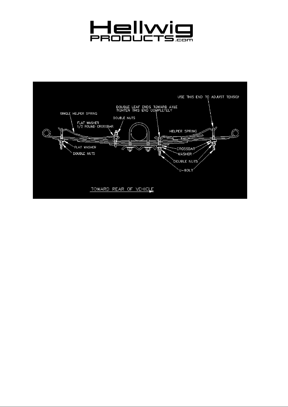
2. Place the accessorysprings on top of the vehicle’s springs as per drawing. On some vehicles it may be necessaryto bend or remove
the vehicle’s spring keepers if the helper spring will not rest down on top of the vehicle’s springs. The helper spring U-bolts will do
the same job as the factory keepers after tightening.
NOTE: The short leaf assembly will mount on the front and the long leaf assembly will mount on the rear of the vehicle leaf springs.
The end where both leaves are clamped together mount toward the axle as close as possible without making contact.
3. Install the U-bolts on theaccessory springs. Install the crossbars, washers and nuts. Tighten the U-bolts on the accessory spring.
Double nut this U-bolt. The shorter U-bolts mount at the axle and the longer U-bolts mount at the spring ands toallow for adjustment.
4. Install the crossbars, washers and nuts on the end U-bolts. Tighten only until enough threads show through to install the lock nut.
5. To adjust the helper spring for more load capacity, remove the lock nut from the end and draw the U-bolt tighter. Be sure to double
nut after each adjustment made.
6. Bounce thevehicle and check for clearance on all undercarriage components. Checkand see that all wiring, brake and fuel lines
are free and clear of this installation.
7. Recheck your installation. Are all the lock nuts installed? Are theU-bolts closest to the axle drawn down completelytight? After on
week of driving recheck your installation, check to see that the helper springs are tight and have not shifted.
ATTENTION INSTALLER: BE SURE THAT THE CUSTOMERRECEIVES THIS INSTRUCTION SHEET,
ALL IMORTANT NOTE CARDS AND THE WARRANTY FORM
( R-1565 ) 02/25/2010
 Loading...