

Hellwig 1560 User Manual
559-734-7451 800-367-5480 FAX 559-734-7460
INSTALLATION INSTRUCTIONS
Thank you for purchasing a quality Hellwig Product.
PLEASE READ THIS INSTRUCTION SHEET COMPLETELY BEFORE STARTING YOUR INSTALLATION PROCEDURES.
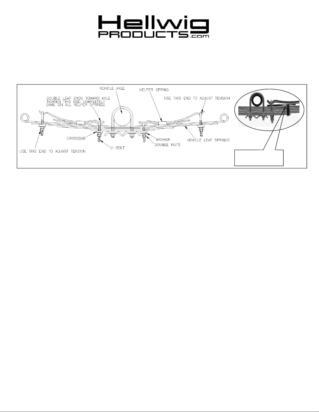
VEHICLE SPRING
CLIP AND SPACER
TORQUE TABLEBOLT SIZE:
3/8” = 20-30 ft. lbs. – 7/16” = 35-45 ft. lbs. – ½” = 50-70 ft. lbs. – 9/16” = 70-90 ft. lbs.-5/8”=120 ft. lbs.
SAFETY
:
IMPORTANT NOTE:
CAPACITY OF YOUR VEHICLE. NEVER LOAD THE VEHICLE THAT THIS HELPER SPRING
IS MOUNTED ON BEYOND THE MANUFACTURER’S MAXIMUM GROSS VEHICLE WEIGHT.
NOTE:
READ INSERT (R-362)
NOTE: Your spring may have a small hole in the end, this is for our manufacturing process and will not be used.
NOTE:
NOTE:
VEHILES SPRINGS MOUNTING CLIPS ( SEE INSERT IN ABOVE DIAGRAM ).
IF YOUR VEHICLE IS EQUIPPED WITH A BRAKE FLUID PROPORTIONING VALVE ON THE REAR AXLE
DO NOT INSTALL THIS UNIT ON ANY VEHICLE WITH PLASTIC COMPOSITE LEAF SPRINGS.
SOME INSTALLATIONS MAY REQUIRE THE USE OF SPACER BRACKETS SUPPLLIED TO HELP CLEAR THE
BEFORE STARTING YOUR INSTALLATION, BE SURE TO SET PARKING BRAKE AND CHOCK TIRES.
HELLWIG HELPER SPRINGS ARE DESIGNED TO INCREASE THE “LEVEL LOAD”CARRYING
1.
Jack up the vehicle by the frame so that the rear wheels are slightly touching the ground. Be sure to use safety stands and block
the front tires.
2. Place the accessory springs on top of the vehicles as per drawing. On some vehicles it may be necessary to bend or remove the vehicles spring keepers, so that the helper spring will rest on top of the vehicles springs. The helper spring U-bolts will do the same job
as the factory keepers after tightening.
NOTE: The short leaf assembly will mount on the front and the long leaf assembly will mount to the rear of the vehicles springs.
The end where both leaves are clamped together mount as close as possible to the axle without making contact.
3. Install the crossbar, washers and nuts on the U-bolts closest to the axle. Tighten down completely and double nuts.
4. Install the crossbar, washers and nuts on the end U-bolts. Tighten just enough to allow the lock nut to be installed.
5. Lower the vehicle to the ground. Tighten and adjust the helper spring for desired tension and height. To adjust the helper spring for
more load capacity draw the nuts tighter, loosen to relief load capacity. Make certain that double nuts are used after each and every
adjustment made.
6. Bounce the vehicle and check for clearance on all under carriage components. Check and see that all wiring, brake and fuel lines are
free of this installation.
7. After one week of driving recheck your installation readjust if necessary. Recheck on a regular monthly basis thereafter.
ATTENTION INSTALLER:
BE SURE THAT THE CUSTOMER RECEIVES THIS INSTRUCTION SHEET,
ALL IMORTANT NOTE CARDS AND THE WARRANTY FORM
1560 ( R-227)
11/28/2012
 Loading...