

559-734-7451 800-367-5480 FAX 559-734-7460
INSTALLATION INSTRUCTIONS
Thank you for purchasing a quality Hellwig Product.
PLEASE READ THIS INSTRUCTION SHEET COMPLETELY BEFORE STARTINGYOUR INSTALLATION
1
2
TORQUE TABLEBOLT SIZE:
3/8” = 20-30 ft. lbs. – 7/16” = 35-45 ft. lbs. – ½” = 50-70 ft. lbs. – 9/16” = 70-90 ft. lbs.-5/8”=120 ft. lbs.
SAFETY: BEFORE STARTING YOUR INSTALLATION, BE SURE TO SET PARKING BRAKE AND CHOCK TIRES.
IMPORTANT NOTE: HELLWIG HELPER SPRINGS ARE DESIGNED TO INCREASE THE “LEVEL LOAD” CARRY-
ING CAPACITY OF YOUR VEHICLE. NEVER LOAD THE VEHICLE THAT THIS HELPER
SPRING IS MOUNTED ON BEYOND THE MANUFACTURER’S MAXIMUM GROSS VEHICLE
WEIGHT.
1. Be sure the vehicle is on hard flat surface and use tire blocks and jack stands. Jack up the vehicle by the frame until
the tires are slightly touching the floor.
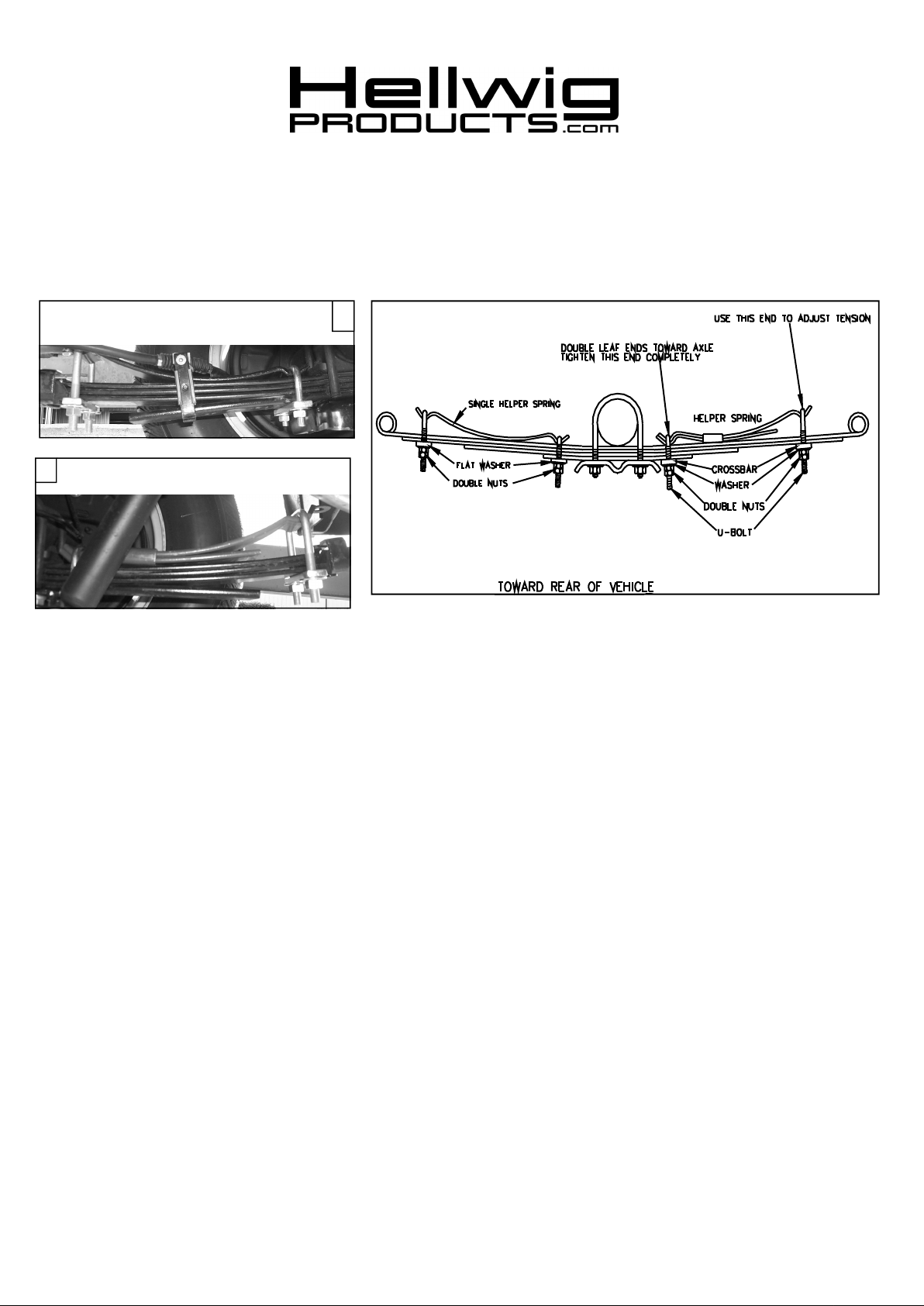
2. Place the accessory spring on top of the truck’s spring as per photos. Remove the emergency brake cable from it’s
mounting bracket to install the front leaf assembly. Keep the mounting bolt and nut to mount the emergency brake
cable when the installation is completed.
NOTE: The single leaf will mount on the front of the vehicle’s leaf springs.( see photo (1). The 2-leaf
assembly will mount on the rear of the vehicle’s leaf springs ( see photo (2).
3. Install the U-bolts on the accessory springs, install the crossbar, washers and nuts. The shorter of the U-bolts will
mount at the axle, the longer will mount at the springs ends to allow for adjustment. Tighten the U-bolts closest to the
axle completely. Double nut these U-bolts.
4. Install the crossbar, washer and nut on the end U-bolts. Tighten just enough that enough threads show through to install a lock nut on the ends.
5. To adjust the springs for more load capacity , remove the lock nut from the end U-bolts and draw the U-bolt tighter.
Be sure to double nut again after each time that an adjustment is made.
6. Reinstall the emergency brake cable to the mounting bracket from where it was removed in step (2).
7. Bounce the vehicle check for clearance on all undercarriage components; wiring, brake and fuel lines.
8. Recheck your installation. Are all the lock nuts installed? Are the U-bolts closest to the axle drawn down completely?
After one week of driving recheck your installation. Make sure that the springs are tight and have not shifted.
ATTENTION INSTALLER: BE SURE THAT THE CUSTOMER RECEIVES THIS INSTRUCTION SHEET,
ALL IMORTANT NOTE CARDS AND THE WARRANTY FORM
1520 ( R-1520 ) 03/01/04

559-734-7451 800-367-5480 FAX 559-734-7460
PARTS LIST
KIT # 1520
PART # QTY DESCRIPTION
20101517 2 SINGLE LEAF 2-1/4” X 14-3/4" LONG
20191516 2 2 LEAF PACK .323 X 2-1/4” X 14-1/2" LONG
118000390 4 (1/2” X 2-5/8” X 4-5/8”) SQUARE U-BOLT
118000067 4 (7/16” X 2-5/8” X 3-3/4”) SQUARE U-BOLT
112070068 8 CROSSBAR
125000022 SMALL PARTS BAG # BG-22
102520043 8 (1/2”) FLAT WASHER
105521044 16 (1/2”) HEX NUT
125000016 SMALL PARTS BAG # BG-16
102420041 8 (7/16”) FLAT WASHER
105421042 16 (7/16”) HEX NUT
135001520 1 INSTRUCTION SHEET R-1520
1520 ( R-1520) 03/01/04
 Loading...