

Hellwig 1510 User Manual
559-734-7451 800-367-5480 FAX 559-734-7460
INSTALLATION INSTRUCTIONS
Thank you for purchasing a quality Hellwig Product.
PLEASE READ THIS INSTRUCTIONSHEET COMPLETELYBEFORESTARTING YOUR INSTALLATION
TORQUE TABLE
BOLT SIZE:3/8” = 20-30 ft. lbs. – 7/16” = 35-45 ft. lbs. – ½” = 50-70 ft. lbs. – 9/16” = 70-90 ft. lbs.
SAFETY: BEFORE STARTING YOUR INSTALLATION, BE SURE TO SET PARKINGBRAKE AND CHOCK TIRES.
NOTE: HELLWIG HELPER SPRINGS ARE DESIGNED TO INCREASE THE “LEVEL LOAD” CARRYING CAPACITY
OF YOUR VEHICLE. NEVER LOAD THE VEHICLE THAT THIS UNIT IS BEING INSTALLED ON BEYOND
THE MANUFACTURER’S MAXIMUM GROSS VEHICLE WEIGHT RATING.
NOTE: IF YOUR VEHICLE IS EQUIPPED WITH A BRAKE FLUID PROPORTIONING VALVE ON THE REAR AXLE
NOTE: Your spring may have a small hole in the end, this is for our manufacturing process and will not be used.
1. Be sure the vehicle is on flat hard surface, use tire blocks and safety stands. Raise up the vehicle by the frame so
that the tires are just contacting the floor.
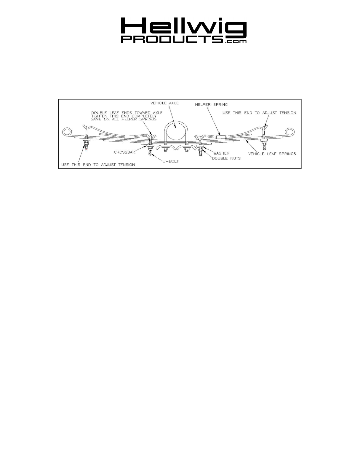
2. Place the accessory springs on top of the vehicle’s springs as per drawing.
NOTE: The short leaf assembly will mount on the front and the long leaf assembly will mount on the rear of
the vehicle leaf springs. Place the leaves as close as possible to the axle without making contact.
3. Install the U-bolts on the accessory springs using the crossbars, washers and nuts which are provided. Install the
1/2” diameter U-bolts and thin crossbars closest to the axle. Install the 9/16” diameter U-bolts and wide crossbars at the ends of the spring. Position the offset of the U-bolt to allow maximum clearance of the crossbars to
the adjacent leaf tip. Tighten the U-bolts closest to the axle completely. Double nut this U-bolt.
4. Install the crossbars, washers and nuts on the end U-bolts. Tighten until enough threads show through to install
the lock nut.
5. To adjust the spring for more load capacity, remove the lock nut from the end U-bolt and draw the U-bolt
tighter. Be sure to double nut after each adjustment made.
6. Bounce the vehicle and check for clearance on all undercarriage components. Check and see that all wiring,
brake and fuel lines are free and clear of this installation.
7. Recheck your installation. Are all the lock nuts installed? Are the U-bolts closest to the axle drawn down completely tight? After one week of driving check your installation to see that it is properly tight and has nit shifted.
Recheck on a monthly regular basis thereafter.
ATTENTION INSTALLER: BE SURE THAT THE CUSTOMER RECEIVES THIS INSTRUCTION SHEET,
ALL IMORTANT NOTE CARDS AND THE WARRANTY FORM
1510 ( R-010 ) 12/16/2011

559-734-7451 800-367-5480 FAX 559-734-7460
PARTS LIST
KIT # 1510
PART # QTY DESCRIPTION
20191519 2 2-LEAF PACK .323” X 2-1/4” X 14-1/2” LONG
20191523 2 2-LEAF PACK .323” X 2-1/4” X 20-1/2" LONG
118000322 4 1/2” X 3-1/4” X 3-7/8” SQUARE U-BOLT
118020003 4 9/16” X 3-1/8” X 4-3/4” COMPOUND SQ U-BOLT
125020230 1 CROSSBAR BAG # BG-233
112070233 4 CROSSBAR
125020080 1 CROSSBAR BAG # BG-580
112070580 4 CROSSBAR
125000022 1 SMALL PARTS BAG # BG-22
102520043 8 1/2” FLAT WASHER
105521044 16 1/2” HEX NUT
125020062 1 SMALL PARTS BAG # BG-61
102620059 4 9/16” FLAT WASHER
105621055 8 9/16” HEX NUT
135000010 1 INSTRUCTION SHEET # R-010
1510 ( R-010 ) 12/16/2011
 Loading...