

Hellwig 14141 User Manual
559-734-7451 800-367-5480 FAX 559-734-7460
INSTALLATION INSTRUCTIONS
Thank you for purchasing a quality Hellwig Product.
PLEASE READ THIS INSTRUCTION SHEET COMPLETELY BEFORE STARTING YOUR INSTALLATION PROCEDURES.
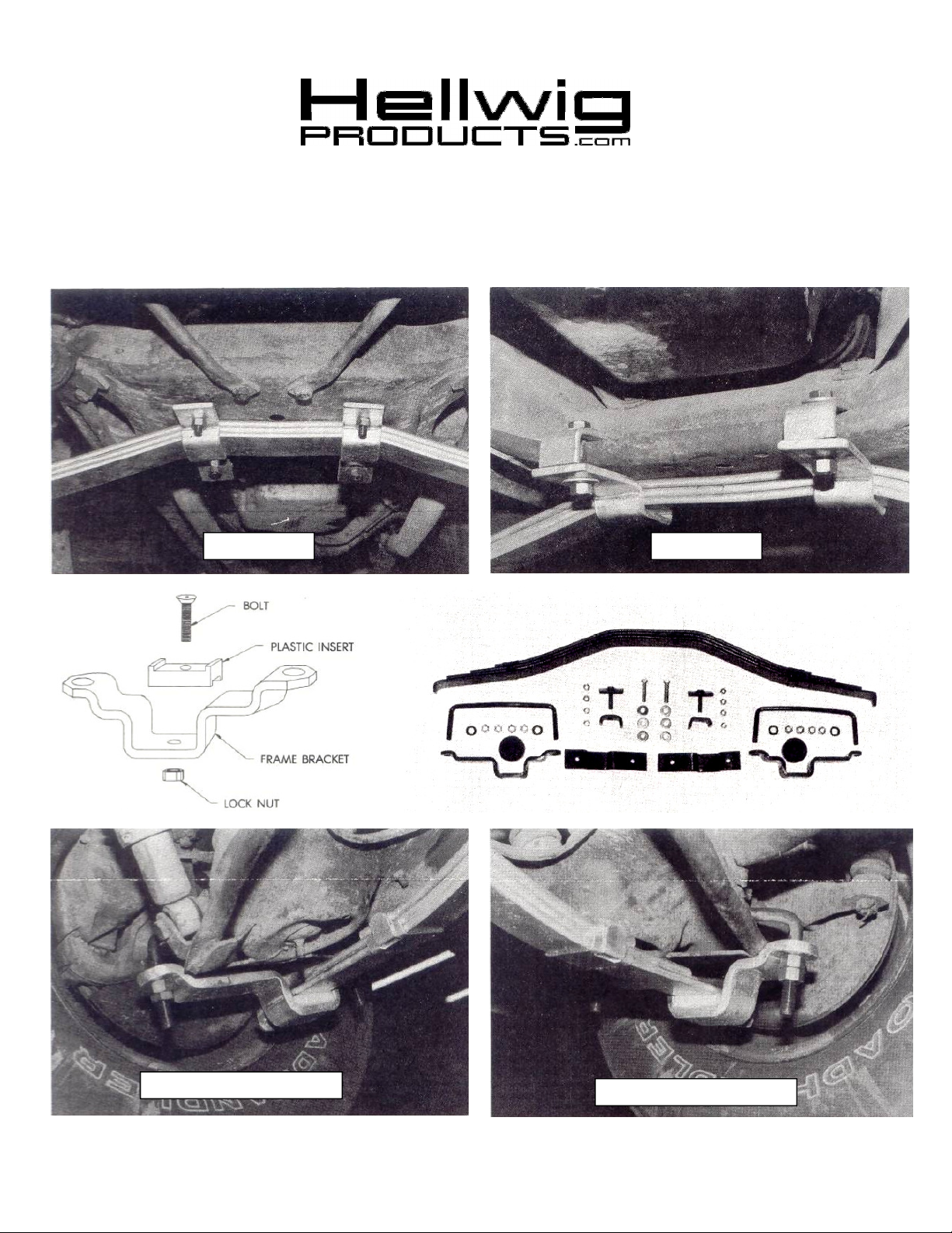
2 Rear View 1 Front View
4 Driver’s Side Rear View
( R-266 ) 11/29/2012
4 Driver’s Side Front View

559-734-7451 800-367-5480 FAX 559-734-7460
TORQUE TABLE
BOLT SIZE: 3/8” = 20-30 ft. lbs. – 7/16” = 35-45 ft. lbs. – 1/2” = 50-70 ft. lbs. – 9/16” = 70-90 ft. lbs
NOTE: A HYDRAULIC FLOOR JACK IS RECOMMENDED TO COMPLETE THIS INSTALLATION. BE SURE TO BLOCK OR
NOTE: THIS UNIT IS NOT RECOMMENDED FOR VEHICLES WITH FRONT LEVELING JACKS.
CHOCK REAR WHEELS AND APPLY EMERGENCY BRAKE.
1. Using the access holes on each side of the center cross member, place the cap screw with a plate
welded to it down though the existing holes as shown in Photo #1.
2. With a jack or help from another person, positions the transverse spring on the center cross member approximately centered between the left and right front wheels. Install both spring retainer
plates as shown in Photos #1 and 2. Be sure to use flat washers on all bolts. Leave loose at this
point.
3. Install both 5/8” U-bolts as in Photos #3 and 4 between the coil spring and rubber snubber. The
bend in the U-bolt will wrap around the rubber snubber bracket. Jack the vehicle up by the cross
member approximately 6-8” inches. This will relax the vehicle’s suspension and ease the remainder of the installation.
4. Install the white friction pads on to the control arm brackets as per the diagram. Be sure not to
over tighten the bolts or damage to the pads will result. Tighten the bolts until the head is below
the contact surface of the pad and will not come into contact with the spring.
5. Install the control arm brackets on to the U-bolts, the short end of the bracket goes toward the
front of the vehicle as in the Photo #4. install the washers and nuts and tighten until the spring is
resting in the pad grooves. Use the spacer tubes to locate the nuts down the U-bolt threads if
needed.
6. Center the transverse spring from left to right by measuring from the steel lip on each front wheel
to each end of the new spring. Lower the vehicle and remove the floor jack. Check to see that the
spring is still centered. If not, jack up the vehicle and repeat the above procedure.
7. Once the spring is centered, tighten the center cross member hardware to 80 ft-lbs on all four (4)
bolts and place a second nut on each bolt as a lock nut.
8. Place the ajck under the left side of spring and raise up to remove tension from U-bolts. Tighten
the U-bolt nuts completely. Take note in Photos #3 and 4 how the lower control arm rests in the
radius of the lower control arm bracket. Complete both sides and double nut each U-bolt leg after
tightening them to 100 ft-lbs. Remove jacks.
9. Check your installation, be sure all nuts and bolts are tightened as described. Turn front wheels
full lock left, then right, making sure there is clearance both front and rear of tires in both directions. Look for clearance on all undercarriage components.
10. Recheck your installation after a test drive, look for clearance on gas lines, steering, exhaust
pipes, brake lines, wiring, etc and check torques. After one week of driving check your installation and periodically thereafter.
ATTENTION INSTALLER: BE SURE THAT THE CUSTOMER RECEIVES THIS INSTRUCTION
( R-266 ) 11/29/2012
SHEET, ALL IMPORTANT NOTE CARDS AND THE WARRANTY FORM.
 Loading...