

HKTS 2 Home Theater & Music Speaker System
OWNER’S MANUAL

Table of Contents
3 Introduction
4 Rear Panel Connections
6 Speaker Placement
7 Mounting Options
8 Speaker Connections
12 Operation
12 Volume
12 Additional Bass Adjustments
13 Troubleshooting
14 Specifications
Declaration of Conformity
We, Harman Consumer Group International
2, Route de Tours
72500 Château-du-Loir,
FRANCE
declare in own responsibility, that the product described in this
owner’s manual is in compliance with technical standards:
EN 61000-6-3:2001
EN 61000-6-1:2001
EN 55013:2001
EN 55020:2002
EN 61000-3-2:2000
EN 61000-3-3:1995+A1:2001
EN 60065:2002
Jurjen Amsterdam
Harman Kardon Europe
03/09
Typographical Conventions
In order to help you use this manual, certain conventions have been used.
Example – (bold type) indicates a specific control or rear-panel connection on the subwoofer
EXAMPLE
– (number in a circle) indicates a rear-panel control or connection on the subwoofer
– (OCR type) indicates a control or switch position on the subwoofer
2 TABLE OF CONTENTS

Introduction
Introduction
Thank you for purchasing the Harman Kardon
HKTS 2, with which you’re about to begin many
years of listening enjoyment. The HKTS 2 has
been custom-designed to provide all the
excitement and power of the music and cinema
experience in your own living room.
While sophisticated electronics and state-of-theart speaker components are hard at work within
the HKTS 2, hookup and operation are simple.
Color-keyed cables and connections, and simple
controls make the HKTS 2 easy to use.
To obtain maximum enjoyment from your new
music and home theater speaker system, we
urge you to take a few minutes to read through
this manual. This will ensure that connections to
your receiver or preamp/processor and amplifier
or other external devices are made properly. In
addition, a few minutes spent learning the functions of the various controls will enable you to
take advantage of all the power and refinement
the HKTS 2 is able to deliver.
If you have any questions about this product, its
installation or operation, please contact your
dealer, the best local source of information.
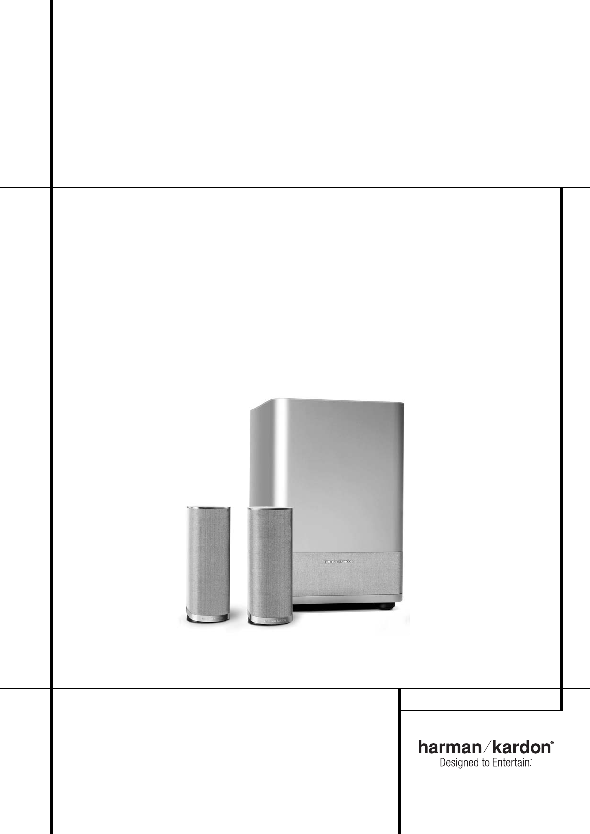
Description and Features
The HKTS 2 is a three-piece home theater
speaker system that includes a 10-inch,
200-watt, bass-reflex powered subwoofer; two
identical, 2-way dual-driver satellite speakers for
use in the left and right front speaker positions;
shelf stands and wall-mount brackets for the
two satellites; and all of the speaker cables you
need to connect your speakers to your receiver
or preamp/processor and amplifier. The speaker
cables and speakers all use a color-coding
system to conform to the CEA standard. The
color-coding system minimizes confusion,
especially when the HKTS 2 system is used with
a Harman Kardon receiver.
The HKTS 2 subwoofer is easy to connect to your
system, since it’s equipped with a special subwoofer input for use with equipment that has a
dedicated subwoofer connection that carries a
low-frequency output. It also includes stereo
speaker-level inputs and outputs for connection
to older receivers and processors that do not
have a line-level subwoofer output. Other conveniences include a level control, high-cut
(low-pass) filter switch and phase switch for
fine-tuning bass response to suit your listening
environment and taste, and an efficient Trigger
switching system that automatically switches the
unit from Standby mode to Active mode.
Shelf stands and wall-mount brackets are included for the satellite speakers, and optional HTFS 2
floor stands are available separately from your
Harman Kardon dealer.
Harman Kardon invented the high-fidelity receiver fifty years ago. With state-of-the-art features
and time-honored circuit designs, the HKTS 2 is
a perfect complement to a Harman Kardon
receiver or any home theater system.
■ Complete 2.1 home theater and music
speaker system
■ Speakers are magnetically shielded for
placement near video monitors
■ Fully color-coded cables and
connections simplify setup
■ Both line- and speaker-level inputs for
use with most audio components
■ Subwoofer input offers superior-quality
bass reproduction when used with any
digital audio system that incorporates
bass management or programmable
crossovers
Included
One powered
subwoofer
Two satellites for left,
right and surrounds,
with color-key stickers
(shown with included
shelf stands attached)
Two wall-mount
brackets
One RCA cable for connection to subwoofer
(purple)
Two 6-meter speaker cables for connection to
front satellites (red and white)
INTRODUCTION 3

Rear Panel Connections
RISK OF ELECTRIC SHOCK
DO NO T OPEN
CAUTION
RISK OF ELECTRIC SHOCK
DO NO T OPEN
CAUTION
RISK OF ELECTRIC SHOCK
DO NO T OPEN
SUB-TS2
For use with
HKTS 2BQ,HKTS 2WQ
HKTS 2 System
Subwoofer-Level Control
High-Cut (Low-Pass) Filter Switch
Trigger Input
Phase Switch
Subwoofer-Level Control: Volume
may be adjusted using the Subwoofer-Level
Control. Turn the control clockwise to increase
the subwoofer’s volume, or counterclockwise to
decrease it.
High-Cut (Low-Pass) Filter Switch: Placing this switch in the
ON
position activates circuitry that cuts out all audio input signals above
120Hz. This allows the subwoofer to focus its
power on reproducing the low-frequency portion
of the signal, avoiding inefficiency and
distortion. Engage this filter when using the
Speaker-Level Inputs
Line-Level Full-Range Inputs
, or when using the
, unless your
receiver or processor processes its line-level
output using a low-pass filter. The filter has no
effect when the Sub Input
is used.
Line-Level Subwoofer (SUB) Input
Line-Level Full-Range Inputs
Speaker-Level Outputs
Speaker-Level Inputs
Trigger Input: Some receivers or sound
processors have a Trigger Output that sends a
signal to the subwoofer to switch on or off. If
your receiver has such a Trigger Output, connect
it here. When placed in the
when the Master Power Switch
AUTO
position, and
is turned
on, the subwoofer will automatically turn itself
on or place itself in the Standby mode,
depending on the status of your receiver or
processor. When this switch is placed in the
ON
position, the subwoofer will remain on, whether
or not it is receiving an audio signal.
Master Power Switch
AC Power Cord
An LED located on top of the subwoofer
indicates whether the subwoofer is in the On or
standby state when used with the Trigger
On/Off Switch
in the
AUTO
position. The
LED is lit blue to indicate that the subwoofer is
receiving an audio signal and is turned on, and
the LED is lit amber to indicate that no signal is
being received and the subwoofer is in Standby
mode.
When the Trigger On/Off Switch
ON
position, the LED will be lit blue, whether or
is in the
not an audio signal is present.
When the Master Power Switch
is turned
off, the LED goes dark, no matter which position
the Trigger On/Off Switch
is in.
4 REAR PANEL CONNECTIONS

Rear Panel Connections
Phase Switch: This switch determines
whether the subwoofer’s piston-like action
moves in and out in phase with the main speakers. If the speakers were to play out of phase,
the sound waves produced by the subwoofer
would be cancelled out, reducing bass response.
This phenomenon depends in part on the relative placement of the speakers in the room. In
most cases, the Phase Switch
left in the
NORMAL
position. However, it does
no harm to experiment with the Phase Switch
, and you may leave it in the position that
maximizes bass response.
Line-Level Subwoofer (SUB) Input: Connect the subwoofer output of a receiver with
digital surround sound decoding, such as Dolby*
Digital or DTS
®
, to this input. This input bypasses
the subwoofer’s internal crossover circuitry, and
should only be used with a filtered signal. If your
receiver does not have digital decoding, you
should use the Line-Level Full-Range Inputs
instead.
Line-Level Full-Range Inputs: Connect
the line-level subwoofer output or preamp output(s) of your receiver or amplifier to these
inputs. If your receiver does not have a separate
subwoofer output, use a Y-adapter (not supplied)
to bridge the receiver’s preamp output to the
main amp input for that channel, and connect
the long end of the adapter to the corresponding line-level input on the subwoofer. If your
receiver has only a single subwoofer output, you
may connect it to either the left or right linelevel input on the subwoofer, and no Y-adapter is
needed.
Speaker-Level Outputs: If you are using
the Speaker-Level Inputs
subwoofer, you should connect these bindingpost terminals to your front left and right speakers, remembering to maintain polarity by connecting the (+) terminal on the subwoofer to the
(+) terminal on the speaker, and the (–) terminal
on the subwoofer to the (–) terminal on the
speaker. If you are not using the Speaker-Level
Inputs
, then connect your front left and
right speakers directly to your receiver or
amplifier. See pages 9 through 12 for further
information on speaker connections.
should be
on the
Speaker-Level Inputs: Connect these
binding-post terminals to the main left and right
speaker terminals of your receiver or amplifier, if
your receiver or amplifier does not have a linelevel subwoofer output. Remember to maintain
polarity by connecting the (+) terminal on the
receiver/amplifier to the (+) terminal on the subwoofer, and the (–) terminal on the receiver/
amplifier to the (–) terminal on the subwoofer.
Master Power Switch: Place this switch in
the “•” position to power-on the subwoofer. The
subwoofer will then be either in the Standby
mode or completely on, depending on the
position of the Trigger On/Off Switch
AC Power Cord: Make sure to plug this
.
cord into an active, unswitched electrical outlet
for proper operation of the subwoofer.
The cord should not be plugged into the
accessory outlets found on some audio
components.
REAR PANEL CONNECTIONS 5
 Loading...