

Page 1

Jade's Collection .net Archives
1
CHAPTER ONE
GENERAL INFORMATION
This detailed and comprehensive manual covers
the Harley-Davidson Dyna Glide Twin Cam 88
model from 1999-on. Procedures and specifications
unique to 2002-2005 models are covered in the
Supplement at the end of the manual. The text provides complete information on maintenance,
tune-up, repair and overhaul. Hundreds of photos
and drawings guide the reader through every job.
A shop manual is a reference tool and as in all
service manuals, the chapters are thumb tabbed for
easy reference.
end of the book. All procedures, tables and figures
are designed for the reader who may be working on
the vehicle for the first time. Frequently used specifications and capacities from individual chapters
are summarized in the Quick Reference Data at the
front of the book.
Tables 1-9 are at the end of this chapter.
Table 1 lists model designation.
Table 2 lists general vehicle dimensions.
Important items are indexed at the
Table 3 lists vehicle weight.
Table 4 lists decimal and metric equivalents.
Table 5 lists conversion tables.
Table 6 lists general torque specifications.
Table 7 lists technical abbreviations.
Table 8 lists American tap and drill sizes.
Table 9 lists special tools.
MANUAL ORGANIZATION
All dimensions and capacities are expressed in
metric and U.S. standard units of measurement.
This chapter provides general information on
shopsafety,tooluse,servicefundamentalsand shop
supplies. The tables at the end of the chapter include
general vehicle information.
Chapter Two provides methods for quick and accurate diagnosis of problems. Troubleshooting pro
cedures present typical symptoms and logical
methods to pinpoint and repair the problem.
-
Page 2

2 CHAPTER ONE
Chapter Three explains all routine maintenance
necessary to keep the vehiclerunning well.Chapter
Three also includes recommended tune-up procedures, eliminating the need to constantly consult the
chapters on the various assemblies.
Subsequent chapters describe specific systems
such as engine, transmission, clutch, drive system,
fuel and exhaust systems, suspension and brakes.
Each disassembly, repair and assembly procedure is
discussed in step-by-step form.
Some of the procedures in this manual specify
special tools. In most cases, the tool is illustrated in
use. Well-equipped mechanics may be able to substitute similar tools or fabricate a suitable replacement. However, in some cases, the specialized
equipment or expertise needed may make it impractical for the home mechanic to attempt the procedure. When necessary, such operations are
identified in the text with the recommendation to
have a dealership or specialist perform the task. It
may be less expensive to have a professional perform these jobs, especially when considering the
cost of the equipment.
WARNINGS, CAUTIONS AND NOTES
The terms, WARNING, CAUTION and NOTE
have specific meanings in this manual.
A WARNING emphasizes areas where injury or
even death could result from negligence. Mechanical damage may also occur. WARNINGS are to be
taken seriously.
ACAUTION emphasizes areas where equipment
damage could result. Disregarding a CAUTION
could cause permanent mechanical damage, though
injury is unlikely.
ANOTEprovides additional information to make
a step or procedure easier or clearer. Disregarding a
NOTE could cause inconvenience, but would not
cause equipment damage or personal injury.
SAFETY
Professional mechanics can work for years and
never sustain a serious injury or mishap. Follow
these guidelines and practice common sense to
safely service the vehicle.
1. Do not operate the vehicle in an enclosed area.
The exhaust gasses contain carbon monoxide, an
odorless, colorless, and tasteless poisonous gas.
Carbon monoxide levels build quickly in small en
closed areas and can cause unconsciousness and
death in a short time. Make sure the work area is
properly ventilated or operate the vehicle outside.
2. Never use gasoline or any extremely flammable
liquid to clean parts. Refer to Cleaning Parts and
Handling Gasoline Safely in this chapter.
3. Never smoke or use a torch in the vicinity of
flammable liquids, such as gasoline or cleaning solvent.
4. If welding or brazing on the vehicle, remove the
fuel tank, carburetor and shocks to a safe distance at
least 50 ft. (15 m) away.
5. Use the correct type and size of tools to avoid
damaging fasteners.
6. Keep tools clean andin good condition. Replace
or repair worn or damaged equipment.
7. When loosening a tight fastener, be guided by
what would happen if the tool slips.
8. When replacing fasteners, make sure the new
fasteners are of the same size and strength as the
original ones.
9. Keep the work area clean and organized.
10. Wear eye protection anytime the safety of the
eyes is in question. This includes procedures involving drilling, grinding, hammering, compressed
air and chemicals.
11. Wear the correct clothing for the job. Tie up or
cover long hair so it can not get caught in moving
equipment.
12. Do not carry sharp tools in clothing pockets.
13. Always have an approved fire extinguisher
available. Make sure it is rated for gasoline (Class
B) and electrical (Class C) fires.
14. Do not use compressed air to clean clothes, the
vehicle or the work area. Debris may be blown into
the eyes or skin. Never direct compressed air at anyone. Do not allow children to use or play with any
compressed air equipment.
15. When using compressed air to dry rotating
parts, hold the part so itcan not rotate.Do not allow
the force of the air to spin the part. The air jet is capable of rotating parts at extreme speed. The part
may be damaged or disintegrate, causing serious injury.
16. Do not inhale the dust created by brake padand
clutch wear. These particles may contain asbestos.
In addition, some types of insulating materials and
gaskets may contain asbestos. Inhaling asbestos
particles is hazardous to health.
-
Page 3

GENERAL INFORMATION 3
17. Never work on the vehicle while someone is
working under it.
18. When placing the vehicle on a stand, make sure
it is secure before walking away.
Handling Gasoline Safely
Gasoline is a volatile flammable liquidand is one
of the most dangerous items in the shop. Because
gasoline is used so often, many people forget that it
is hazardous. Only use gasoline as fuel for gasoline
internal combustion engines. Keep in mind, when
working on a vehicle, gasoline is always present in
the fuel tank, fuel line and carburetor. Toavoid a disastrous accident when working around the fuel
system, carefully observe the following precautions:
1. Never use gasoline to clean parts. See Cleaning
Parts in this chapter.
2. When working on the fuel system, work outside
or in a well-ventilated area.
3. Donot add fuel tothe fuel tank or service the fuel
system while the vehicle is near open flames, sparks
or where someone is smoking. Gasoline vapor is
heavier than air,it collects in low areas and is more
easily ignited than liquid gasoline.
4. Allow the engine to cool completely before
working on any fuel system component.
5. When draining the carburetor,catch the fuel in a
plastic container and then pour it into an approved
gasoline storage device.
6. Do notstore gasoline in glass containers. If the
glass breaks, a serious explosion or fire may occur.
7. Immediately wipe up spilled gasoline with rags.
Store the rags in a metal container with a lid until
they can be properly disposed of, or place them outside in a safe place for the fuel to evaporate.
8. Do not pour water onto a gasoline fire. Water
spreads the fire and makes it more difficult to put
out. Use a class B, BC or ABC fire extinguisher to
extinguish the fire.
9. Always turn off the engine before refueling. Do
not spill fuel onto the engine or exhaust system. Do
not overfill the fuel tank. Leave an air space at the
top of the tank to allow room for the fuel to expand
due to temperature fluctuations.
Cleaning Parts
1
Cleaning parts is one of the more tedious and difficult service jobs performed in the home garage.
There are many types of chemical cleaners and solvents available for shop use. Most are poisonous
and extremely flammable. To prevent chemical exposure, vapor buildup, fire and serious injury, observe each product warning label and note the
following:
1. Read and observe the entire product label before
using any chemical. Always know what type of
chemical is being used and whether it is poisonous
and/or flammable.
2. Do not use more than one type of cleaning solvent at a time. If mixing chemicals is called for,
measure the proper amounts according to the manufacturer.
3. Work in a well-ventilated area.
4. Wear chemical-resistant gloves.
5. Wear safety glasses.
6. Wear a vapor respirator if the instructions call
for it.
7. Wash hands and arms thoroughly after cleaning
parts.
8. Keep chemical products away from children and
pets.
9. Thoroughly clean all oil, grease and cleaner residue from any part that must be heated.
10. Use a nylon brush when cleaning parts. Metal
brushes may cause a spark.
11. When using a parts washer,only use the solvent
recommended by the manufacturer. Make sure the
parts washer is equipped with a metal lid that will
lower in case of fire.
Warning Labels
Most manufacturers attach information and
warning labels to the vehicle. These labels contain
instructions that are important to personal safety
when operating, servicing, transporting and storing
the vehicle. Refer to the owner’s manual for the description and location of labels. Order replacement
labels from the manufacturer if they are missing or
damaged.
Page 4

Jade's Collection .net Archives
4 CHAPTER ONE
SERIAL NUMBERS
Serial numbers are stamped on various locations
on the frame, engine, transmission and carburetor.
Record these numbers in the Quick Reference Data
section in the front of the book. Have these numbers
available when ordering parts.
Theframe serial number (Figure 1) is stamped on
the right side of the frame down tube.
The VIN number label (Figure 2) is located just
below the frame number on the right side frame
down tube.
Engine serial number is stamped on a pad on the
left side of the crankcase (Figure 3), as well as the
right side of the crankcase (Figure 4).
The transmission serial number (Figure 5) is
stamped on a pad on the right side of the transmission case next to the side door.
The carburetor serial number (Figure 6) is located on the side of the carburetor body next to the
accelerator pump linkage.
Table 1 lists model designation.
FASTENERS
1
2
Proper fastener selection and installation is im-
portant to ensure that the vehicle operates as de-
signedand can be serviced efficiently.The choice of
original equipment fasteners is not arrived at by
chance. Make sure that replacement fasteners meet
all the same requirements as the originals.
Threaded Fasteners
Threaded fasteners secure most of the components on the vehicle. Most are tightened by turning
them clockwise (right-hand threads). If the normal
rotation of the component being tightened would
loosen the fastener,it may haveleft-hand threads. If
a left-hand threaded fastener is used, it is noted in
the text.
Two dimensions are required to match the threads
of the fastener: the number of threads in a given distance and the outside diameter of the threads.
Two systems are currently used to specify
threaded fastener dimensions: the U.S. Standard
system and the metric system (Figure 7). Pay particular attention when working with unidentified
fasteners; mismatching thread types can damage
threads.
3
4
Page 5

GENERAL INFORMATION 5
5
8
-9.8
Grade marking
T
D
L
1
NOTE
6
To ensure that the fastener threads are
not mismatched or cross-threaded,
start all fasteners by hand. If a fastener is hard to start or turn, determine the cause before tightening with
a wrench.
The length (L, Figure 8), diameter (D) and dis-
tance between thread crests (pitch) (T) classify metric screws and bolts. A typical bolt may be
identified by the numbers, 8—1.25 × 130. This indicates the bolt has diameter of 8 mm, the distance between thread crests is 1.25 mm and the length is 130
mm. Always measure bolt length as shown in Fig-
7
ure 8 to avoid purchasing replacements of the
wrong length.
The numbers located on the top of the fastener
(Figure 8) indicate the strength of metric screws
and bolts. The higher the number, the stronger the
fastener is. Unnumbered fasteners are the weakest.
American Metric
Many screws, bolts and studs are combined with
nuts to secure particular components. To indicate
the size of a nut, manufacturers specify the internal
diameter and the thread pitch.
The measurement across two flats on a nut or bolt
indicates the wrench size.
60°
60°
WARNING
Do not install fasteners with a
strength classification lower than
what was originally installed by the
manufacturer. Doing so may cause
equipment failure and/or damage.
Torque Specifications
The materials used in the manufacture of the ve
hicle may be subjected to uneven stresses if the fas
-
-
Page 6
6 CHAPTER ONE
teners of the various subassemblies are not installed
and tightened correctly. Fasteners that are improp-
9
erly installed or work loose can cause extensive
damage. It is essential to use an accurate torque
wrench, described in this chapter, with the torque
specifications in this manual.
Specifications for torque are provided in New-
ton-meters (N•m), foot-pounds (ft.-lb.) and
inch-pounds (in.-lb.). Refer to Table 6 for general
torque specifications. To use Table 6, first deter-
Correct
installation of
cotter pin
mine the size of the fastener as described in Fasteners in this chapter. Torque specifications for
specific components are at the end of the appropriate chapters. Torque wrenches are covered in the
Basic Tools section.
Self-Locking Fasteners
Several types of bolts, screws and nuts incorporate a system that creates interference between the
two fasteners. Interference is achieved in various
ways. The most common type is the nylon insert nut
and a dry adhesive coating on the threads of a bolt.
10
Self-locking fasteners offer greater holding
strength than standard fasteners, which improves
their resistance to vibration. Most self-locking fasteners cannot be reused. The materials used to form
the lock become distorted after the initial installation and removal. It is a good practice to discard and
Internal snap ring
Plain clip
replace self-locking fasteners after their removal.
Do not replace self-locking fasteners with standard
fasteners.
Washers
There are two basic types of washers: flat washers and lockwashers. Flat washers are simple discs
with a hole to fit a screw or bolt. Lockwashers are
used to prevent a fastener from working loose.
Washers can be used as spacers and seals, or to help
distribute fastener load and to prevent the fastener
from damaging the component.
As with fasteners, when replacing washers make
sure the replacement washers are of the same design
and quality.
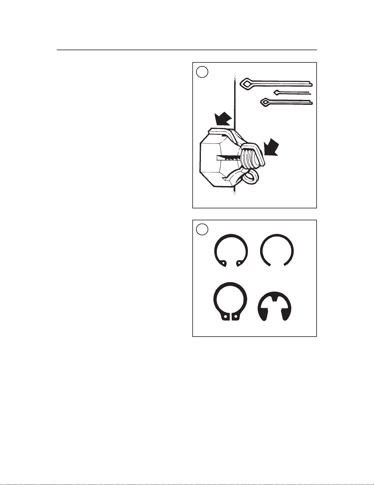
Cotter Pins
A cotter pin is a split metal pin inserted into a hole
or slot to prevent a fastener from loosening. In cer
External snap ring
E-ring
tain applications, such as the rear axle on an ATV or
motorcycle, the fastener must be secured in this
way. For these applications, a cotter pin and castellated (slotted) nut is used.
To use a cotter pin, first make sure the diameter is
correct for the hole in the fastener. After correctly
tightening the fastener and aligning the holes, insert
the cotter pin through the hole and bend the ends
over the fastener (Figure 9). Unless instructed to do
so, never loosen a torqued fastener to align the
holes. If the holes do not align, tighten the fastener
-
just enough to achieve alignment.
Page 7

GENERAL INFORMATION 7
11
Direction
of thrust
12
Full
support
areas
Rounded edges
Sharp edges
Two basic types of snap rings are used: machined
and stamped snap rings. Machined snap rings (Fig-
ure 11) can be installed in either direction, since
both faces have sharp edges. Stamped snap rings
(Figure12) are manufactured with a sharp edge and
a round edge. When installing a stamped snap ring
in a thrust application, install the sharp edge facing
away from the part producing the thrust.
E-clips and circlips are used when it is not practical to use a snap ring. Remove E-clips with a flat
blade screwdriver by prying between the shaft and
E-clip. To install an E-clip, center it over the shaft
groove and push or tap it into place.
Observe the following when installing snap rings:
1. Remove and install snap rings with snap ring pliers. See Snap Ring Pliers in this chapter.
2. In some applications, it may be necessary to replace snap rings after removing them.
3. Compress or expand snap rings only enough to
install them. If overly expanded, they lose their retaining ability.
4. After installing a snap ring, make sure it seats
completely.
5. Wear eye protection when removing and installing snap rings.
1
Direction of thrust
Cotter pins are available in various diameters and
lengths. Measure length from the bottom of the
head to the tip of the shortest pin.
Snap rings and E-clips
Snap rings (Figure 10) are circular-shaped metal
retaining clips. They are required to secure parts
and gears in place on parts such as shafts, pins or
rods. External type snap rings are used to retain
items on shafts. Internal type snap rings secure parts
within housing bores. In some applications, in addition to securing the component(s), snap rings of
varying thickness also determine endplay. These are
usually called selective snap rings.
SHOP SUPPLIES
Lubricants and Fluids
Periodic lubrication helps ensure a long service
life for any type of equipment. Using the correct
type of lubricant is as important as performing the
lubrication service, although in an emergency the
wrong type is better than none. The following section describes the types of lubricants most often required. Make sure to follow the manufacturer’s
recommendations for lubricant types.
Engine oils
Engine oil is classified by two standards: the
American Petroleum Institute (API) service classification and the Society of Automotive Engineers
(SAE) viscosity rating. This information is on the
oil container label. Two letters indicate the API service classification. The number or sequence of
numbers and letter (10W-40 for example) is the oil’s
viscosity rating. The API service classification and
Page 8

8 CHAPTER ONE
the SAE viscosity index are not indications of oil
quality.
The service classification indicates that the oil
meets specific lubrication standards. The first letter
in the classification (S) indicates that the oil is for
gasoline engines. The second letter indicates the
standard the oil satisfies. The classification started
with the letter A and is currently at the letter J.
Always use an oil with a classification recommended by the manufacturer. Using an oil with a
different classification can cause engine damage.
Viscosity is an indication of the oil’s thickness.
Thin oils have a lower number while thickoils have
a higher number. Engine oils fall into the 5- to
50-weight range for single-grade oils.
Most manufacturers recommend multigrade oil.
These oils perform efficiently across a wide range
of operating conditions. Multigrade oils are identified by a W after the first number, which indicates
the low-temperature viscosity.
Engine oils are most commonly mineral (petroleum) based; however, synthetic and semi-synthetic
types are used more frequently. When selecting engine oil, follow the manufacturer’s recommendation for type, classification and viscosity when
selecting engine oil.
Greases
Grease is lubricating oil with thickening agents
added to it. The National Lubricating Grease Institute (NLGI) grades grease. Grades range from No.
000 to No. 6, with No. 6 being the thickest. Typical
multipurpose grease is NLGI No. 2. For specific applications, manufacturers may recommend water-resistant type grease or one with an additive
such as molybdenum disulfide (MoS
).
2
Brake fluid
Brake fluid is the hydraulic fluid used to transmit
hydraulic pressure (force) to the wheel brakes.
Brake fluid is classified by the Department of
Transportation (DOT). Current designations for
brake fluid are DOT 3, DOT 4 and DOT 5. This
classification appears on the fluid container.
Each type of brake fluid has its own definite characteristics. The Harley-Davidson Dyna Glide uses
the silicone based DOT 5 brake fluid. Do not inter
mix DOT 3 or DOT 4 type brake fluid as this may
cause brake system failure since the DOT 5 brake
fluid is not compatible with other brake fluids.
When adding brake fluid, only use the fluid recommended by the manufacturer.
Brake fluid will damage any plastic, painted or
plated surface it contacts. Use extreme care when
working with brake fluid and remove any spills immediately with soap and water.
Hydraulic brake systems require clean and moisture free brake fluid. Never reuse brake fluid. Keep
containers and reservoirs properly sealed.
WARNING
Never put a mineral-based (petroleum) oil into the brake system. Mineral oil will cause rubber parts in the
system to swell and break apart, resulting in complete brake failure.
Cleaners, Degreasers and Solvents
Many chemicals are available to remove oil,
grease and other residue from the vehicle. Before
using cleaning solvents, consider how they will be
usedand disposed of, particularlyif they are not water-soluble. Local ordinances may require special
procedures for the disposal of many types of cleaning chemicals. Refer to Safety and Cleaning Parts
in this chapter for more information on their use.
Use brake parts cleaner to clean brake system
components when contact with petroleum-based
products will damage seals. Brake parts cleaner
leaves no residue. Use electrical contact cleaner to
clean electrical connections and components without leaving any residue. Carburetor cleaner is a
powerful solvent used to remove fuel deposits and
varnish from fuel system components. Use this
cleaner carefully, as it may damage finishes.
Generally, degreasers are strong cleaners used to
remove heavy accumulations of grease from engine
and frame components.
Most solvents are designed to be used in a parts
washingcabinet for individual component cleaning.
For safety, use only nonflammable or high flash
point solvents.
Gasket Sealant
Sealants are used in combination with a gasket or
seal and are occasionally alone. Follow the manu
facturer’s recommendation when using sealants.
-
Page 9

GENERAL INFORMATION 9
13
Use extreme care whenchoosing a sealant different
from the type originally recommended. Choose
sealants based on their resistance to heat, various
fluids and their sealing capabilities.
One of the most common sealants is RTV, or
room temperature vulcanizing sealant. This sealant
cures at room temperature over a specific time period. This allows the repositioning of components
without damaging gaskets.
Moisture in the air causes the RTV sealant to
cure. Always install the tube cap as soon as possible
after applying RTVsealant. RTV sealant has a limited shelf life and will not cure properly if the shelf
life has expired. Keep partial tubes sealed and discard them if they have surpassed the expiration
date.
moval process and prevent damage to the mating
surface that may be caused by using a scraping tool.
Most of these types of products are very caustic.
Follow the gasket remover manufacturer’s instructions for use.
Threadlocking Compound
A threadlocking compound is a fluid applied to
the threads of fasteners. After tightening the fastener, the fluid dries and becomes a solid filler between the threads. This makes it difficult for the
fastener to work loose from vibration, or heat expansion and contraction. Some threadlocking compounds also provide a seal against fluid leakage.
Before applying threadlocking compound, remove any old compound from both thread areas and
clean them with aerosol parts cleaner. Use the compoundsparingly.Excess fluid can run into adjoining
parts.
Threadlockingcompounds are available in different strengths. Follow the particular manufacturer’s
recommendations regarding compound selection.
Two manufacturers of threadlocking compound are
ThreeBond and Loctite. They both offer a wide
range of compounds for various strength, temperature and repair applications.
BASIC TOOLS
1
Applying RTV sealant
Clean all old gasket residue from the mating surfaces. Remove all gasket material from blind
threaded holes; it can cause inaccurate bolt torque.
Spray the mating surfaces with aerosol parts cleaner
and then wipe with a lint-free cloth. The area must
be clean for the sealant to adhere.
Apply RTV sealant in a continuous bead 2-3 mm
(0.08-0.12 in.) thick. Circle all the fastener holes
unless otherwise specified. Do not allow any sealant to enter these holes. Assemble and tighten the
fasteners to the specified torque within the time
frame recommended by the RTV sealant manufacturer.
Gasket Remover
Aerosol gasket remover can help remove stub
born gaskets. This product can speed up the re
Most of the proceduresin this manual can be carried out with simple hand tools and test equipment
familiar to the home mechanic. Always use the correct tools for the job at hand. Keep tools organized
and clean. Store them in a tool chest with related
tools organized together.
Quality tools are essential. The best are constructed of high-strength alloy steel. These tools are
light, easy to use and resistant to wear. Their working surface is devoid of sharp edges and the tool is
carefully polished. They have an easy-to-clean finish and are comfortable to use. Quality tools are a
good investment.
When purchasing tools to perform the procedures
covered in this manual, consider the tools’potential
frequency of use. If a tool kit is just now being
started, consider purchasing a basic tool set (Figure
13) from a large tool supplier. These sets are avail
able in many tool combinations and offer substan
tial savings when compared to individually
-
-
-
Page 10

10 CHAPTER ONE
purchased tools. As work experience grows and
tasks become more complicated, specialized tools
can be added.
Screwdrivers
Screwdrivers of various lengths and types are
mandatory for the simplest tool kit. The two basic
types are the slotted tip (flat blade) and the Phillips
tip. These are available in sets that often include an
assortment of tip sizes and shaft lengths.
As with all tools, use a screwdriver designed for
the job. Make sure the size of the tip conforms to the
size and shape of the fastener. Use them only for
driving screws. Never use a screwdriver for prying
or chiseling metal. Repair or replace worn or damaged screwdrivers. A worn tip may damage the fastener, making it difficult to remove.
14
15
Wrenches
Open-end, box-end and combination wrenches
(Figure14) are available in various types and sizes.
The number stamped on the wrench refers to the
distance between the work areas. This size must
match the size of the fastener head.
The box-end wrench is an excellent tool because
it grips the fastener on all sides. This reduces the
chance of the tool slipping. The box-end wrench is
designed with either a 6- or 12-point opening. For
stubborn or damaged fasteners, the 6-point provides
superior holding ability by contacting the fastener
across a wider area at all six edges. For general use,
the 12-point works well. It allows the wrench to be
removed and reinstalled without moving the handle
over such a wide arc.
An open-end wrench is fast and works best in areas with limited overhead access. It contacts the fastener at only two points, and is subject to slipping
under heavy force, or if the tool or fastener is worn.
A box-end wrench is preferred in most instances,
especially when breaking loose and applying the
final tightness to a fastener.
The combination wrench has a box end on one
end and an open end on the other. This combination
makes it a very convenient tool.
16
Adjustable Wrenches
An adjustable wrench or Crescent wrench (Fig-
ure 15) can fit nearly any nut or bolt head that has
clear access around its entire perimeter. Adjustable
wrenches are best used as a backup wrench to keep
a large nut or bolt from turning while the other end
is being loosened or tightened with a box-end or
socket wrench.
Adjustable wrenches contact the fastener at only
two points, making them more likely to slip off the
fastener. The fact that one jaw is adjustable and may
Page 11

GENERAL INFORMATION 11
17
18
19
the socket is the size of the work area and must
match the fastener head.
As with wrenches, a 6-point socket provides superior holding ability, while a 12-point socket needs
to be moved only half as far to reposition it on the
fastener.
Sockets are designated for either hand or impact
use. Impact sockets are made of thicker material for
more durability. Compare the size and wall thick-
ness of a 19-mm hand socket (A, Figure 18) and the
19-mm impact socket (B). Use impact sockets when
using an impact driver or air tools. Use hand sockets
with hand-driven attachments.
WARNING
Do not use hand sockets with air or
impact tools, as they may shatter and
cause injury. Always wear eye protection when using impact or air tools.
Various handles are available for sockets. The
speed handle is used for fast operation. Flexible
ratchet heads in varying lengths allow the socket to
be turned with varying force, and at odd angles. Extension bars allow the socket setup to reach difficult
areas. The ratchet is the most versatile. It allows the
user to install or remove the nut without removing
the socket.
Sockets combined with any number of drivers
make them undoubtedly the fastest, safest and most
convenient tool for fastener removal and installation.
1
loosen only aggravates this shortcoming. Make certain that the solid jaw is the one transmitting the
force.
Socket Wrenches, Ratchets and Handles
Sockets that attach to a ratchet handle (Figure16)
are available with 6-point (A, Figure 17) or
12-point (B) openings and different drive sizes. The
drive size indicates the size of the square hole that
accepts the ratchet handle. The number stamped on
Impact Driver
An impact driver provides extra force for removing fasteners, by converting the impact of a hammer
into a turning motion. This makes it possible to remove stubborn fasteners without damaging them.
Impact drivers and interchangeable bits (Figure 19)
are available from most tool suppliers. When using
a socket with an impact driver make sure the socket
is designed for impact use. Refer to Socket
Wrenches, Ratchets and Handles in this section.
WARNING
Do not use hand sockets with air or
impact tools as they may shatter and
cause injury. Always wear eye protec
tion when using impact or air tools.
-
Page 12

12 CHAPTER ONE
Allen Wrenches
Allen or setscrew wrenches (Figure 20) are used
on fasteners with hexagonal recesses in the fastener
head. These wrenches are available in L-shaped bar,
socket and T-handle types. A metric set is required
when working on most vehicles. Allen bolts are
sometimes called socket bolts.
Torque Wrenches
A torque wrench is used with a socket, torque
adapter or similar extension to tighten a fastener
o a measured torque. Torque wrenches come in several drive sizes (1/4, 3/8, 1/2 and 3/4) and have various methods of reading the torque value. The drive
size indicates the size of the square drive that accepts the socket, adapter or extension. Common
methods of reading the torque value are the deflecting beam, the dial indicator and the audible click
(Figure 21).
When choosing a torque wrench, consider the
torque range, drive size and accuracy. The torque
specifications in this manual provide an indication
of the range required.
A torque wrench is a precision tool that must be
properly cared for to remain accurate. Store torque
wrenches in cases or separate padded drawers
within a toolbox. Follow the manufacturer’s instructions for their care and calibration.
20
21
22
Torque Adapters
Torque adapters or extensions extend or reduce
the reach of a torque wrench. The torque adapter
shown in Figure 22 is used to tighten a fastener that
cannot be reached due to the size of the torque
wrench head, drive, and socket. If a torque adapter
changes the effective lever length (Figure 23), the
torque reading on the wrench will not equal the actual torque applied to the fastener. It is necessary to
recalibrate the torque setting on the wrench to compensate for the change of lever length. When a
torque adapter is used at a right angle to the drive
head, calibration is not required, since the effective
length has not changed.
To recalculate a torque reading when using a
torque adapter, use the following formula, and refer
to Figure 23.
TW = TA ×L
L + A = E
TW is the torque setting or dial reading on the
wrench.
TA is the torque specification and the actual
amount of torque that will be applied to the fastener.
A is the amount that the adapter increases (or in
some cases reduces) the effective lever length as
measured along the centerline of the torque wrench
(Figure 23).
L is the lever length of the wrench as measured
from the center of the drive to the center of the grip.
Page 13

GENERAL INFORMATION 13
23
HOW TO MEASURE TORQUE WRENCH EFFECTIVE LENGTH
L
L
L+A= Effective length
L
L= Effective length
L
No calculation needed
A
A
1
24
The effective length is the sum of L and A (Fig-
ure 23).
Example:
TA = 20 ft.-lb.
A = 3 in.
L = 14 in.
E = 17 in.
TW = 20×14
= 280 = 16.5 ft. Lb.
14 +3 = 17
In this example, the torque wrench would be set
to the recalculated torque value (TW = 16.5 ft.-lb.) .
25
When using a beam-type wrench, tighten the fastener until the pointer aligns with 16.5 ft.-lb. In this
example, although the torque wrench is preset to
16.5 ft.-lb., the actual torque is 20 ft.-lb.
Pliers
Pliers come in a wide range of types and sizes.
Pliers are useful for holding, cutting, bending, and
crimping. Do not use them to turn fasteners. Figure
24 and Figure 25 show several types of useful pli
-
Page 14

14 CHAPTER ONE
26
ers. Each design has a specialized function.
Slip-joint pliers are general-purpose pliers used for
gripping and bending. Diagonal cutting pliers are
needed to cut wire and can be used to remove cotter
pins. Needlenose pliers are used to hold or bend
small objects. Locking pliers (Figure 25), some-
times called Vise-grips, are used to hold objects
very tightly. They have many uses, ranging from
holding two parts together to gripping the end of a
broken stud. Use caution when using locking pliers,
as the sharp jaws will damage the objects they hold.
27
28
Snap Ring Pliers
Snap ring pliers are specialized pliers with tips
that fit into the ends of snap rings to remove and install them.
Snap ring pliers are available with a fixed action
(either internal or external) or convertible (one
tool works on both internal and external snap
rings). They may have fixed tips or interchangeable ones of various siz es and angles. For general
use, select a convertible type pliers with interchangeable tips.
WARNING
Snap rings can slip and fly off when
removing and installing them. Also,
the snap ring pliers tips may break.
Always wear eye protection when using snap ring pliers.
Hammers
Various types of hammers (Figure 26) are avail-
able to fit a number of applications. A ball-peen
hammer is used to strike another tool, such as a
punch or chisel. Soft-faced hammers are required
when a metal object must be struck without damaging it. Never use a metal-faced hammer on engine
and suspension components, as damage will occur
in most cases.
Always wear eye protection when using hammers. Make sure the hammer face is in good condition and the handle is not cracked. Select the correct
hammer for the job and make sure to strike the object squarely. Do not use the handle or the side of the
hammer to strike an object.
PRECISION MEASURING TOOLS
The ability to accurately measure components is
essential to successfully rebuild an engine. Equipment is manufactured to close tolerances, and obtaining consistently accurate measurements is
essential to determining which components require
replacement or further service.
Each type of measuring instrument is designed to
measure a dimension with a certain degree of accuracy and within a certain range. When selecting the
measuring tool, make sure it is applicable to the
task.
Page 15

GENERAL INFORMATION 15
29
Aswith all tools, measuringtools provide the best
results if cared for properly.Improper use can damage the tool and result in inaccurate results. If any
measurement is questionable, verify the measurementusing another tool. Astandardgauge is usually
provided with measuring tools to check accuracy
and calibrate the tool if necessary.
Precision measurements can vary according to
the experience of the person performing the procedure. Accurate results are only possible if the mechanic possesses a feel for using the tool.
Heavy-handed use of measuring tools will produce
less accurate results. Hold the tool gently by the fingertips so the point at which the tool contacts the
object is easily felt. This feel for the equipment will
produce more accurate measurements and reduce
therisk of damaging thetool or component. Referto
thefollowing sections for specific measuring tools.
Feeler Gauge
The feeler or thickness gauge (Figure27) is used
for measuring the distance between two surfaces.
A feeler gauge set consists of an assortment of
steel strips of graduated thickness. Each blade is
marked with its thickness. Blades can be of various
lengths and angles for different procedures.
10.00 mm
0.50 mm
10.55 mm
0.400 mm
0.013 mm
0.413 mm
Moveable scaless
Fixed scale
A common use for a feeler gauge is to measure
valve clearance. Wire (round) type gauges are used
to measure spark plug gap.
Calipers
Calipers (Figure 28) are excellent tools for obtaining inside, outside and depth measurements. Although not as precise as a micrometer, they allow
reasonable precision, typically to within 0.05 mm
(0.001 in.). Most calipers have a range up to 150
mm (6 in.).
Calipers are available in dial, vernier or digital
versions. Dial calipers have a dial readout that provides convenient reading. Vernier calipers have
marked scales that must be compared to determine
the measurement. The digital caliper uses an LCD
to show the measurement.
Properly maintain the measuring surfaces of the
caliper.There must not be any dirt or burrs between
the tool and the object being measured. Never force
thecaliper closed around an object; close the caliper
around the highest point so it can be removed with a
slight drag. Some calipers require calibration. Always refer to the manufacturer’s instructions when
using a new or unfamiliar caliper.
To read a vernier caliper refer, to Figure 29. The
fixed scale is marked in 1 mm increments.Tenindi
1
-
Page 16

16 CHAPTER ONE
30
DECIMAL PLACE VALUES*
0.1 Indicates 1/10 (one tenth of an inch
0.010 Indicates 1/100 (one one-hundreth of
0.001 Indicates 1/1,000 (one one-thousandth
*This chart represents the values of figures placed to the right of the decimal point. Use it when
reading decimals from one-tenth to one one-thousandth of an inch or millimeter. It is not a con-
version chart (for example: 0.001 in. is not equal to 0.001 mm).
or millimeter)
an inch or millimeter)
of an inch or millimeter)
vidual lines on the fixed scale equal 1 cm. The
moveable scale is marked in 0.05 mm (hundredth)
31
increments. To obtain a reading, establish the first
number by the location of the 0 line on the movable
scale in relation to the first line to the left on the
fixed scale. In this example, the number is 10 mm.
To determine the next number, note which of the
lines on the movable scale align with a mark on the
fixed scale. A number of lines will seem close, but
only one will align exactly. In this case, 0.50 mm is
the reading to add to the first number. The result of
adding 10 mm and 0.50 mm is a measurement of
10.50 mm.
Reading a Micrometer
Micrometers
Amicrometer is an instrument designed for linear
measurement using the decimal divisions of the
inch or meter (Figure 30). While there are many
types and styles of micrometers, most of the procedures in this manual call for an outside micrometer.
The outside micrometer is used to measure the outside diameter of cylindrical forms andthe thickness
of materials.
A micrometer’s size indicates the minimum and
maximum size of a part that it can measure. The
usual sizes (Figure 31) are 0-1 in. (0-25 mm), 1-2
in. (25-50 mm), 2-3 in. (50-75 mm) and 3-4 in.
(75-100 mm).
Micrometersthat cover a wider range of measurements are available. These use a large frame with
interchangeable anvils of various lengths.This type
of micrometer offers a cost savings; however, its
overall size may make it less convenient.
When reading a micrometer, numbers are taken
from different scales and added together. The following sections describe how to read the measurements of various types of outside micrometers.
For accurate results, properly maintain the measuring surfaces of the micrometer. There cannot be
any dirt or burrs between the tool and the measured
object. Never force the micrometer closed around
an object. Close the micrometer around the highest
pointso it can beremoved with a slight drag. Figure
32 shows the markings and parts of a standard inch
micrometer.Be familiar withthese terms before using a micrometer in the following sections.
Standard inch micrometer
The standard inch micrometer is accurate to
one-thousandth of an inch or 0.001. The sleeve is
marked in 0.025 in. increments. Every fourth sleeve
Page 17

GENERAL INFORMATION 17
32
33
STANDARD INCH MICROMETER
Sleeve line
Thimble marks
Sleeve
Frame
1. Largest number visible on the
sleeve line
2. Number on sleeve marks visible
between the numbered sleeve mark
and the thimble edge
3. Thimble mark that aligns with
sleeve line
Anvil
Sleeve
Spindle
Thimble
Locknut
Thimble
numbers
1
Ratchet
0.200 in.
0.025 in.
0.006 in.
mark is numbered 1, 2, 3, 4, 5, 6, 7, 8, 9. These numbers indicate 0.100, 0.200, 0.300, and so on.
The tapered end of the thimble has twenty-five
lines marked around it. Each mark equals 0.001 in.
One complete turn of the thimble will align its zero
mark with the first mark on the sleeve or 0.025 in.
When reading a standard inch micrometer, perform the following steps while referring to Figure
33.
1. Read the sleeve and find the largest number visible. Each sleeve number equals 0.100 in.
2. Count the number of lines between the numbered sleeve mark and the edge of the thimble. Each
sleeve mark equals 0.025 in.
3. Read the thimble mark that aligns with the
sleeve line. Each thimble mark equals 0.001 in.
Total reading
0.231 in.
NOTE
If a thimble mark does not align exactly with the sleeve line, estimate the
amount between the lines. For accurate readings in ten-thousandths of an
inch (0.0001 in.), use a vernier inch
micrometer.
4. Add the readings from Steps 1-3.
Vernier inch micrometer
A vernier inch micrometer is accurate to one
ten-thousandth of an inch or 0.0001 in. It has the
same marking as a standard inch micrometer with
an additional vernier scale on the sleeve (Figure
34).
Page 18

18 CHAPTER ONE
34
35
Vernier scale
1. Largest number visible on
Sleeve
Vernier scale
Sleeve
Thimble
Thimble
sleeve line
2. Number of sleeve marks visible
between the numbered sleeve mark
and the thimble edge
3. Thimble is between 0.018 and 0.019
in. on the sleeve line
4. Vernier line coinciding with
thimble line
STANDARD METRIC MICROMETER
Sleeve line
Thimble
Anvil
Locknut
Spindle
Total reading
0.100 in.
0.050 in.
0.018 in.
0.0003 in.
0.1683 in.
Sleeve marks
The vernier scale consists of 11 lines marked 1-9
with a 0 on each end. These lines run parallel to the
thimble lines and represent 0.0001 in. increments.
Whenreading a vernier inch micrometer, perform
the following steps while referring to Figure 34.
1. Read the micrometer in the same way as a standard micrometer. This is the initial reading.
2. If a thimble mark aligns exactly with the sleeve
line, reading the vernier scale is not necessary. If
they do not align, read the vernier scale in Step 3.
3. Determine which vernier scale mark aligns with
one thimble mark. The vernier scale number is the
Thimble marks
Ratchet
amount in ten-thousandths of an inch to add to the
initial reading from Step 1.
Metric micrometer
The standard metric micrometer (Figure 35) is
accurate to one one-hundredth of a millimeter
(0.01-mm). The sleeve line is graduatedin millimeter and half millimeter increments. The marks on
the upper half of thesleeve lineequal 1.00mm. Ev
ery fifth mark above the sleeve line is identified
with a number. The number sequence depends on
-
Page 19

GENERAL INFORMATION 19
36
Sleeve
Sleeve
Thimble
Thimble
the size of themicrometer. A 0-25 mm micrometer,
for example, will have sleeve marks numbered 0
through 25 in 5 mm increments. This numbering sequence continues with larger micrometers. On all
metric micrometers, each mark on the lower half of
the sleeve equals 0.50 mm.
Thetaperedendof thethimblehas 50 linesmarked
aroundit. Each mark equals0.01 mm. One complete
turnof thethimblealigns its0 mark with the first line
on the lower halfof the sleeve line or 0.50mm.
When reading a metricmicrometer, add the number of millimeters and half-millimeters on the
sleeve line to the number of one one-hundredth millimeterson the thimble. Perform the following steps
while referring to Figure 36.
1. Read the upper half of the sleeve line and count
the number of lines visible. Each upper line equals 1
mm.
2. See if the half-millimeter line is visible on the
lower sleeve line. If so, add 0.50 mm to the reading
in Step 1.
3. Read the thimble mark that aligns with the
sleeve line. Each thimble mark equals 0.01 mm.
1. Reading on upper sleeve line
2. Reading on lower sleeve line
3. Thimble line coinciding with
sleeve line
Total reading
5.00 mm
0.50 mm
0.18 mm
5.68 mm
Metric vernier micrometer
Ametric vernier micrometer (Figure 37) is accu-
rate to two-thousandths of a millimeter (0.002 mm).
It has the same markings as a standard metric micrometer with the addition of a vernier scale on the
sleeve.
The vernier scale consists of five lines marked 0,
2, 4, 6, and 8. Theselines run parallelto the thimble
lines and represent 0.002-mm increments.
When reading a metric vernier micrometer, perform the following steps and refer to Figure 37.
1. Read the micrometer in the same way as a standard metric micrometer. This is the initial reading.
2. If a thimble mark aligns exactly with the sleeve
line, reading the vernier scale is not necessary. If
they do not align, read the vernier scale in Step 3.
3. Determine which vernier scale mark aligns exactly with one thimble mark. The vernier scale
number is the amount in two-thousandths of a millimeter to add to the initial reading from Step 1.
Micrometer Adjustment
1
NOTE
If a thimble mark does not align exactly with the sleeve line, estimate the
amount between the lines. For accurate readings in two-thousandths of a
millimeter (0.002 mm), use a metric
vernier micrometer.
4. Add the readings from Steps 1-3.
Before using a micrometer, check its adjustment
as follows.
1. Clean the anvil and spindle faces.
2A. To check a 0-1 in. or 0-25 mm micrometer:
a. Turnthe thimble until the spindle contacts the
anvil. If the micrometer has a ratchet stop, use
it to ensure that the proper amount of pressure
is applied.
Page 20

20 CHAPTER ONE
37
38
Vernier scale
Sleeve
Vernier scale
Sleeve
Thimble
Thimble
1. Reading on upper sleeve line
2. Reading on lower sleeve line
3. Thimble is between 0.15 and 0.16
mm on the sleeve line
4. Vernier line coinciding with
thimble line
Total reading
39
4.0 mm
0.5 mm
0.15 mm
0.008 mm
4.658 mm
b. If the adjustment is correct, the 0 mark on the
thimble will align exactly with the 0 mark on
the sleeve line. If the marks do not align, the
micrometer is out of adjustment.
c. Follow the manufacturer’s instructions to ad-
just the micrometer.
2B. To check a micrometer larger than 1 in. or 25
mm use the standard gauge supplied by the manufacturer. A standard gauge is a steel block, disc or
rod that is machined to an exact size.
a. Place the standard gauge between the spindle
and anvil, and measure its outside diameter or
length. If the micrometer has a ratchet stop,
use it to ensure that the proper amount of
pressure is applied.
b. If the adjustment is correct, the 0 mark on the
thimble will align exactly with the 0 mark on
the sleeve line. If the marks do not align, the
micrometer is out of adjustment.
c. Follow the manufacturer’s instructions to ad-
just the micrometer.
Micrometer Care
Micrometers are precision instruments. They
must be used and maintained with great care. Note
the following:
1. Storemicrometers in protectivecases or separate
padded drawers in a toolbox.
2. When in storage, make sure the spindle and anvil
faces do not contact each other or another object. If
they do, temperature changes and corrosion may
damage the contact faces.
3. Do not clean a micrometer with compressed air.
Dirt forced into the tool will cause wear.
4. Lubricate micrometers with WD-40 to prevent
corrosion.
Page 21

GENERAL INFORMATION 21
40
41
42
themovable post in position.Remove the gauge and
measure the length of the posts. Telescoping gauges
are typically used to measure cylinder bores.
To use a small-bore gauge, select the correct size
gauge for the bore. Carefully insert the gauge into
the bore. Tighten the knurled end of the gauge to
carefully expand the gauge fingers to the limit
within the bore. Do not overtighten the gauge, as
there is no built-in release. Excessive tightening can
damage the bore surface and damage the tool. Remove the gauge and measure the outside dimension
(Figure40). Small hole gauges are typically used to
measure valve guides.
Dial Indicator
Adial indicator (Figure 41) is agauge with adial
face and needle used to measure variations in dimensions and movements. Measuring brake rotor
runout is a typical use for a dial indicator.
Dialindicators are available in various ranges and
graduations and with three basic types of mounting
bases: magnetic, clamp, or screw-in stud. When
purchasing a dial indicator, select the magnetic
stand type with a continuous dial.
1
Telescoping and
Small Bore Gauges
Use telescoping gauges (Figure 38) and small
hole gauges (Figure 39) to measure bores. Neither
gauge has a scale for direct readings. An outside micrometer must be used to determine the reading.
To use a telescoping gauge, selectthe correct size
gauge for the bore. Compress the movable post and
carefully insert the gauge into the bore. Carefully
move the gauge in the bore to make sure it is cen
tered. Tighten the knurled end of the gauge to hold
Cylinder Bore Gauge
A cylinder bore gauge is similar to a dial indica-
tor. The gauge set shown in Figure42 consists of a
dial indicator, handle, and different length adapters
(anvils) to fit the gauge to various bore sizes. The
bore gauge is used to measure bore size, taper and
out-of-round. When using a bore gauge, follow the
manufacturer’s instructions.
Compression Gauge
Acompression gauge (Figure43) measures com-
bustion chamber (cylinder) pressure, usually in psi
or kg/cm
2
. The gauge adapter is either inserted or
screwed into the spark plug hole to obtain the reading. Disable the engine so it will not start and hold
the throttle in the wide-open position when performing a compression test. An engine that does not
-
have adequate compression cannot be properly
tuned. See Chapter Three.
Page 22

22 CHAPTER ONE
43
Multimeter
A multimeter (Figure 44) is an essential tool for
electrical system diagnosis. The voltage function
indicates the voltage applied or available to various
electrical components. The ohmmeter function tests
circuits for continuity, or lack of continuity, and
measures the resistance of a circuit.
Some manufacturers’ specifications for electrical
components are based on results using a specific
test meter. Results may vary if a meter not recommend by the manufacturer is used. Such requirements are noted when applicable.
Ohmmeter (analog) calibration
44
Voltage
Voltage is the electrical potential or pressure in an
electrical circuit and is expressed in volts. The more
pressure (voltage) in a circuit, the more work that
can be performed.
Direct current (DC) voltage means the electricity
flows in one direction. All circuits powered by a
battery are DC circuits.
Alternating current (AC) means that the electricity flows in one direction momentarily then
switchesto the opposite direction. Alternator output
is an example of AC voltage. This voltage must be
changed or rectified to direct current to operate in a
battery powered system.
Each time an analog ohmmeter is used or if the
scale is changed, the ohmmeter must be calibrated.
Digital ohmmeters do not require calibration.
1. Makesure the meter battery is in goodcondition.
2. Make sure the meter probes are in good condition.
3. Touch the two probes together and observe the
needle location on the ohms scale.
The needle must align with the 0 mark to obtain
accurate measurements.
4. If necessary, rotate the meter ohms adjust knob
until the needle and 0 mark align.
ELECTRICAL SYSTEM FUNDAMENTALS
A thorough study of the many types of electrical
systems used in today’s vehicles is beyond the
scope of this manual. However, a basic understanding of electrical basics is necessary to perform sim
ple diagnostic tests.
Measuring voltage
Unless otherwise specified, perform all voltage
tests with the electrical connectors attached. When
measuringvoltage, select the meterrange that is one
scale higher than the expected voltage of the circuit
to prevent damage to the meter. To determine the
actual voltage in a circuit, use a voltmeter. To simply check if voltage is present, use a test light.
NOTE
When using a test light, either lead
can be attached to ground.
1. Attach the negative meter test lead to a good
ground (bare metal). Make sure the ground is not insulated with a rubber gasket or grommet.
2. Attach the positive meter test lead to the point
being checked for voltage (Figure 45).
3. Turnon the ignition switch. Thetest light should
-
light or the meter should display a reading. The
readingshould be within onevolt of battery voltage.
Page 23

GENERAL INFORMATION 23
45
Voltmeter
If the voltage is less, there is a problem in the circuit.
Voltage drop test
Resistancecauses voltage to drop. This resistance
can be measured in an active circuitby using avoltmeter to perform a voltage drop test. A voltage drop
test compares the difference between the voltage
available at the start of a circuit to the voltage at the
end of the circuit while the circuit is operational. If
the circuit has no resistance, there will be no voltage
drop. The greater the resistance, the greater the voltage drop will be. A voltage drop of one volt or more
indicates excessive resistance in the circuit.
1. Connect the positive meter test lead to the electrical source (where electricity is coming from).
2. Connect the negative meter test lead to the electrical load (where electricity is going). See Figure
46.
3. If necessary, activate the component(s) in the
circuit.
4. Avoltage reading of 1 volt or more indicates excessive resistance in the circuit. A reading equal to
battery voltage indicates an open circuit.
Resistance
46
Voltage drop
Battery
Resistance is measured in an inactive circuit with
an ohmmeter. The ohmmeter sends a small amount
of current into the circuit and measures how difficult it is to push the current through the circuit.
An ohmmeter, although useful, is not always a
good indicator of a circuit’s actual ability under operating conditions. This is due to the low voltage
(6-9 volts) that the meter uses to test the circuit. The
voltagein an ignition coil secondary winding can be
several thousand volts. Such high voltage can cause
the coil to malfunction, even though it tests acceptable during a resistance test.
Resistance generally increases with temperature.
Perform all testing with the component or circuit at
room temperature. Resistance tests performed at
high temperatures may indicate high resistance
readings and result in the unnecessary replacement
of a component.
Measuring resistance and continuity testing
CAUTION
Only use an ohmmeter on a circuit
that has no voltage present. The meter
will be damaged if it is connected to a
live circuit. An analog meter must be
calibrated each time it is used or the
scale is changed. See Multimeter in
this chapter.
1
Resistance is the opposition to the flow of electricity within a circuit or component and is mea
sured in ohms. Resistance causes a reduction in
available current and voltage.
A continuity test can determine if the circuit is
complete. This type of test is performed with an
ohmmeter or a self-powered test lamp.
1. Disconnect the negative battery cable.
Page 24

24 CHAPTER ONE
2. Attach one test lead (ohmmeter or test light) to
one end of the component or circuit.
3. Attach the other test lead to the opposite end of
the component or circuit (Figure 47).
4. A self-powered test light will come on if the circuit has continuity or is complete. An ohmmeter
will indicate either low or no resistance if the circuit
has continuity. An open circuit is indicated if the
meter displays infinite resistance.
Amperage
Amperage is the unit of measure for the amount
of current within a circuit. Current is the actual flow
of electricity.The higher the current, themore work
that can be performed up to a given point. If the currentflow exceeds the circuit or component capacity,
the system will be damaged.
Measuring amps
An ammeter measures the current flow or amps
ofa circuit (Figure48). Amperage measurement requires that the circuit be disconnected and the ammeter be connected in series to the circuit. Always
use an ammeter that can read higher than the anticipated current flow to prevent damage to the meter.
Connect the red test lead to the electrical source and
the black test lead to the electrical load.
SPECIAL TOOLS
Some of the procedures in this manual require
special tools (Table 9). These are described in the
appropriate chapter and are available from either
the manufacturer or a tool supplier.
In many cases, an acceptable substitute may be
found in an existing tool kit. Another alternative is
tomake the tool. Manyschools with a machineshop
curriculum welcome outside work that can be used
as practical shop applications for students.
BASIC SERVICE METHODS
Most of the procedures in this manual are
straightforward and can be performed by anyone
reasonably competent with tools. However, con
sider personal capabilities carefully before attempt
47
Ohmmeter
Component
ing any operation involving major disassembly of
the engine.
1. Front,in this manual, refersto the front of the vehicle. The front of any component is the end closest
tothe front of the vehicle. The left and right sides refer to the position of the parts as viewedby the rider
sitting on the seat facing forward.
2. Whenever servicing an engine or suspension
component, secure the vehicle in a safe manner.
3. Tag all similar parts for location and mark all
mating parts for position. Record the number and
thickness of any shims as they are removed. Identify parts by placing them in sealed and labeled
plastic sandwich bags.
4. Tag disconnected wires and connectors with
masking tape and a marking pen. Do not rely on
memory alone.
5. Protect finished surfaces from physical damage
or corrosion. Keep gasoline and other chemicalsoff
painted surfaces.
6. Use penetrating oil on frozen or tight bolts.
Avoid using heat where possible. Heat can warp,
melt or affect the temper of parts. Heat also damages the finish of paint and plastics.
7. When a part is a press fit or requires a special
tool for removal, the information or type of tool is
identified in the text. Otherwise, if a part is difficult
toremove or install, determine the cause before proceeding.
8. To prevent objects or debrisfrom falling intothe
engine, cover all openings.
-
9. Read each procedure thoroughly and compare
-
the illustrations to the actual components before
Page 25

GENERAL INFORMATION 25
48
Ammeter
Measures
current
flow
Connected
in series
starting the procedure. Perform theprocedure insequence.
10. Recommendations are occasionally made to
refer service to a dealership or specialist. In
these cases, the work can be performed more
economically by the specialist than by the home
mechanic.
11. The term replace means to discard a defective
part and replace itwith a new part. Overhaul means
to remove, disassemble, inspect, measure, repair
and/orreplace parts as required to recondition an assembly.
12. Some operations require the use of a hydraulic
press. If a press is not available, have these operations performed by ashop equipped with the necessary equipment. Do not use makeshift equipment
that may damage the vehicle.
13. Repairs are much faster and easier if the vehicle is clean before starting work. Degrease the vehicle with a commercial degreaser; follow the
directions on the container for the best results.
Clean allparts with cleaningsolventas theyareremoved.
CAUTION
Do not direct high-pressure water at
steering bearings, carburetor hoses,
wheel bearings, suspension and electrical components, or drive belt. The
water will force the grease out of the
bearings and possibly damage the
seals.
14. If special tools are required, have them available before starting the procedure. When special
tools are required, they will be described at the beginning of the procedure.
15. Make diagrams of similar-appearing parts. For
instance, crankcase bolts are often not the same
lengths. Do not rely onmemory alone. It is possible
that carefully laid out parts will become disturbed,
making it difficult to reassemble the components
correctly without a diagram.
16. Make sure all shims and washers are reinstalled
in the same location and position.
17. Whenever rotating parts contact a stationary
part, look for a shim or washer.
18. Use new gaskets if there is any doubt about the
condition of old ones.
19. If self-locking fasteners are used, replace them
with new ones. Do not install standard fasteners in
place of self-locking ones.
20. Use grease to hold small parts in place if they
tend to fall out during assembly. Do not apply
grease to electrical or brake components.
Removing Frozen Fasteners
If a fastener cannot be removed, several methods
may be used to loosen it. First, applypenetrating oil
such as Liquid Wrenchor WD-40. Apply it liberally
and let it penetrate for 10-15 minutes. Rap the fastener several times with a small hammer.Do not hit
it hard enough to cause damage. Reapply the penetrating oil if necessary.
For frozen screws, apply penetrating oil as described, then insert a screwdriver in the slot and rap
the top of the screwdriver with a hammer. This loosens the rust so the screw can be removed in the normal way. If the screw head is too damaged to use
this method, grip the head with locking pliers and
twist the screw out.
Avoid applying heat unless specifically instructed, as it may melt, warp or remove the temper
from parts.
Removing Broken Fasteners
If the head breaks off a screw or bolt, several
methods are available for removing the remaining
portion. If a large portion of the remainder projects
out, try gripping it with locking pliers. If the pro
1
-
Page 26

26 CHAPTER ONE
49
Filed
Slotted
jecting portion is too small, file it to fit a wrench or
cut a slot in it to fit a screwdriver (Figure 49).
If the head breaks off flush, use ascrew extractor.
To do this, centerpunch the exact center of the remaining portion of the screw or bolt. Drill a small
hole in the screw and tap the extractor into the hole.
Back the screw out with a wrench on the extractor
(Figure 50).
Repairing Damaged Threads
Occasionally, threads are stripped through carelessness or impact damage. Often the threads can be
repaired by running a tap (for internal threads on
nuts) or die (for external threads on bolts) through
the threads (Figure 51). To clean or repair spark
plug threads, use a spark plug tap.
If an internal thread is damaged, it may be necessaryto install a Helicoil or some other type ofthread
insert. Follow the manufacturer’s instructions when
installing their insert.
Ifit is necessary todrill and tap ahole, refer to Ta-
ble 8 for American tap and drill sizes.
50
REMOVING BROKEN
SCREWS AND BOLTS
1. Center punch broken stud 2. Drill hole in stud
3. Tap in screw extractor 4. Remove broken
stud
51
Stud Removal/Installation
A stud removal tool is available from most tool
suppliers. This tool makes theremoval andinstallation of studs easier. If one is not available, thread
two nuts onto the stud and tighten them against each
other. Remove the stud by turning the lower nut
(Figure 52).
1. Measurethe height of the stud above thesurface.
2. Thread the stud removal tool onto the stud and
tighten it, or thread two nuts onto the stud.
3. Remove the stud by turning the stud remover or
the lower nut.
4. Remove any threadlocking compound from the
threaded hole. Clean the threads with an aerosol
parts cleaner.
5. Install the stud removal tool onto the new stud or
thread two nuts onto the stud.
Page 27

GENERAL INFORMATION 27
52
53
Bearing puller
Removing Hoses
1
When removing stubborn hoses, do not exert excessive force on the hose or fitting. Remove the
hose clamp and carefully insert a small screwdriver
or pick tool between the fitting and hose. Apply a
spray lubricant under the hose and carefully twist
the hose off the fitting. Clean the fitting of any corrosion or rubber hose material with a wire brush.
Clean the inside of the hose thoroughly. Do not use
any lubricant when installing the hose (new or old).
Thelubricant may allow the hose to comeoff the fitting, even with the clamp secure.
Bearings
Bearings are used in the engine and transmission
assembly to reduce power loss, heat and noise resulting from friction. Because bearings are precision parts, they must be maintained by proper
lubrication and maintenance. If a bearing is damaged, replace it immediately.When installing a new
bearing, take care to prevent damaging it. Bearing
replacement procedures are included in the individual chapters where applicable; however,use the following sections as a guideline.
Spacer
Shaft
Bearing
6. Apply threadlocking compound to the threads of
the stud.
7. Install the stud and tighten with the stud removal
tool or the top nut.
8. Install the stud to the height noted in Step1 or its
torque specification.
9. Remove the stud removal tool or the two nuts.
NOTE
Unless otherwise specified, install
bearings with the manufacturer’s
mark or number facing outward.
Removal
While bearings are normally removed only when
damaged, there may be times when it is necessary to
remove a bearing that is in good condition. However, improper bearing removal will damage the
bearing and maybe the shaft or case half. Note the
following when removing bearings.
1. When using a puller to remove a bearing from a
shaft, take care that the shaft is not damaged. Always place a piece of metal between the end of the
shaft and the puller screw. In addition, place the
puller arms next to the inner bearing race. See Fig-
ure 53.
2. When using a hammer to remove a bearing from
a shaft, do not strike the hammer directly against the
shaft. Instead, use a brass or aluminum rodbetween
the hammer and shaft (Figure 54) and make sure to
Page 28

28 CHAPTER ONE
54
Spacer
Shaft
Bearing
Blocks
support both bearing races with wooden blocks as
shown.
3. A hydraulic press is the ideal method of bearing
removal. Note the following when using a press:
a. Always support the inner and outer bearing
races with a suitable size wooden or aluminum ring (Figure 55). If only the outer race is
supported, pressure applied against the balls
and/or the inner race will damage them.
b. Always make sure the press arm (Figure 55)
alignswith the center of the shaft. If the arm is
not centered, it may damage the bearing
and/or shaft.
c. The moment the shaftis free of the bearing, it
will drop to the floor. Secure or hold the shaft
to prevent it from falling.
Installation
1. When installing a bearing in a housing, apply
pressure to the outer bearing race (Figure 56).
When installing a bearing on a shaft,apply pressure
to the inner bearing race (Figure 57).
2. When installing a bearing as described in Step
1, sometypeof driver is required.Never strikethe
55
Press ram
Shaft
Bearing
Spacer
Press bed
56
Bearing
Bearing
Housing
bearing directly with a hammer or the bearing
will be damaged. When installing a bearing,usea
piece of pipe or a driver with a diameter that
matches the bearing race. Figure 58 shows the
correct way to use a socket and hammer to install
a bearing.
3. Step1 describes how to install a bearing in a case
half or over a shaft. However, when installing a
bearing over a shaft and into a housing at the same
time, a tight fit will be required for both outer and
inner bearing races. In this situation, install a spacer
underneaththe driver tool so that pressure is applied
evenly across both races. See Figure 59. If the outer
race is not supported as shown in Figure 59, the
balls will push against the outer bearing race and
damage it.
Page 29

GENERAL INFORMATION 29
57
Bearing
Shaft
58
Socket
Bearing
Shaft
Interference Fit
1. Follow this procedure when installing a bearing
over a shaft. When a tight fit is required, the bearing
inside diameter will be smaller than the shaft. In this
case, driving the bearing on the shaft using normal
methods may cause bearing damage. Instead, heat
the bearing before installation. Note the following:
a. Secure the shaft so it is ready for bearing in-
stallation.
b. Cleanallresiduesfromthebearingsurfaceofthe
shaft. Remove burrswitha fileor sandpaper.
59
Driver
Spacer
Bearing
Shaft
Housing
c. Fill a suitable pot or beaker with clean min-
eral oil. Place a thermometer rated above
120° C (248° F) in the oil. Support the thermometer so that it does not rest onthe bottom
or side of the pot.
d. Remove the bearing from its wrapper and se-
cure it with a pieceof heavywire bent to hold
it in the pot. Hang the bearing in the pot so it
doesnot touch the bottom or sides ofthe pot.
e. Turn the heat on and monitor the thermome-
ter.When the oil temperature rises to approximately 120° C (248° F), remove the bearing
from the pot and quickly install it. If necessary, place a socket on the inner bearing race
and tap the bearing into place. As the bearing
chills, it will tighten on the shaft, so installation must be done quickly. Make sure the
bearing is installed completely.
2. Follow this step when installing a bearing in a
housing. Bearings are generally installed in a housingwith a slight interferencefit. Driving the bearing
intothe housing using normal methods may damage
the housing or cause bearing damage. Instead, heat
the housing before the bearing is installed. Note the
following:
CAUTION
Before heating the housing in this pro
cedure, wash the housing thoroughly
with detergent and water. Rinse and
1
Page 30

30 CHAPTER ONE
rewash the cases as required to remove all traces of oil and other chem-
60
ical deposits.
Spring
a. Heat the housing to approximately 212° F
(100° C) in an oven or on a hot plate. An easy
way to check that it is the proper temperature
is to place tiny drops of water on thehousing;
if they sizzle and evaporate immediately, the
temperature is correct. Heat only onehousing
Dust lip
Main
lip
Oil
at a time.
CAUTION
Do not heat the housing with a propane or acetylene torch. Never bring
a flame into contact with the bearing
or housing. The direct heat will destroy the case hardening of the bearing and will likely warp the housing.
b. Remove the housing from the oven or hot
plate, and hold onto the housing with a
kitchen potholder, heavy gloves or heavy
shop cloth. It is hot!
NOTE
Remove and install the bearings with
a suitable size socket and extension.
c. Hold the housing with the bearing side down
and tap the bearing out. Repeat for all bearings in the housing.
d. Before heating the bearing housing, place the
new bearing in a freezer if possible. Chilling a
bearing slightly reduces its outside diameter
while the heated bearing housing assembly is
slightly larger due to heat expansion. This
will make bearing installation easier.
NOTE
Always install bearings with the manufacturer’s mark or number facing
outward.
Reinforcement
Seal Replacement
Seals (Figure 60) are used to contain oil, water,
grease or combustion gasses in a housing or shaft.
Improper removal of a seal can damage thehousing
or shaft. Improper installation of the seal can damage the seal. Note the following:
1. Prying is generally the easiest and most effective
method of removing a seal from a housing. However, always place a rag underneath the pry tool
(Figure 61) to prevent damage to the housing.
2. Pack waterproof grease in the seal lips before the
seal is installed.
3. In most cases, install seals with the manufacturer’s numbers or marks face out.
4. Install seals with a socket placed on the outside
of the seal as shown in Figure 62. Drive the seal
squarely into the housing. Never install a seal by
hitting against the top of the seal with a hammer.
e. While the housing is still hot, install the new
bearing(s) into the housing. Install the bearings by hand, if possible. If necessary, lightly
tap the bearing(s) into the housing with a
socket placed on the outer bearing race (Fig-
ure 56). Do not install new bearings by driving on the inner-bearing race. Install the
bearing(s) until it seats completely.
STORAGE
Several months of non-use can cause a general
deterioration of the vehicle. This is especially true
in areas of extreme temperaturevariations. Thisdeterioration can be minimized with careful preparation for storage. A properly stored vehicle will be
much easier to return to service.
Page 31

GENERAL INFORMATION 31
61
62
Storage Area Selection
When selecting a storage area, consider the fol-
lowing:
1. The storage area must be dry. A heated area is
best, but not necessary. It should be insulated to
minimize extreme temperature variations.
2. If the building has large window areas, mask
them to keep sunlight off the vehicle.
3. Avoid buildings in industrial areas where corrosive emissions may be present. Avoid areas close to
saltwater.
4. Consider the area’s risk of fire, theft or vandalism. Check with an insurer regarding vehicle coverage while in storage.
Preparing the Vehicle for Storage
The amount of preparation a vehicle should un-
dergo before storage depends on the expected
length of non-use, storage area conditions and personal preference. Consider the following list the
minimum requirement:
1. Wash the vehicle thoroughly. Make sure all dirt,
mud and road debris are removed.
2. Start the engine and allow it to reach operating
temperature. Drain the engine oil and transmission
oil, regardless of the riding time since the last service. Fill the engine and transmission with the recommended type of oil.
3. Drain all fuel from the fuel tank, run the engine
until all the fuel is consumed from the lines and carburetor.
4. Remove the spark plugs and pour a teaspoon of
engine oil into the cylinders. Place a rag over the
openings and slowly turnthe engine over to distribute the oil. Reinstall the spark plugs.
5. Remove the battery. Store the battery in a cool
and dry location.
6. Cover the exhaust and intake openings.
7. Reduce the normal tire pressure by 20%.
8. Apply a protective substance to the plastic and
rubber components, including the tires. Make sure
to follow the manufacturer’s instructions for each
type of product being used.
9. Place the vehicle on a stand or wooden blocks,
so the wheels areoff the ground. If this is not possible, place a piece of plywood between the tires and
the ground. Inflate the tires to the recommended
pressure if the vehicle can not be elevated.
10. Cover the vehicle with old bed sheets or something similar. Do not cover it with any plastic material that will trap moisture.
Returning the Vehicle to Service
The amount of service required when returning a
vehicle to service after storage depends on the
length of non-use and storage conditions. In addition to performing the reverse of the above procedures, make sure the brakes, clutch, throttle and
engine stop switch work properly before operating
the vehicle. Refer to Chapter Three and evaluate the
service intervals to determine which areas require
service.
1
Tables 1-9 are on the following pages
Page 32

32 CHAPTER ONE
Table 1 MODEL DESIGNATION
1999-2000
FXDS-CONV Dyna Convertable
1999-on
FXD Dyna Super Glide
FXDX Dyna Super Glide Sport
FXDL Dyna Low Rider
FXDWG Dyna Wide Glide
FXDXT Dyna Glide T-Sport
FXDP Dyna Defender (law enforcement model)
Table 2 GENERAL DIMENSIONS
Item/model in. mm
Wheelbase
FXDWG 66.10 1678.95
FXDS-CONV 63.88 1622.55
FXDL 65.60 1666.24
FXD 62.80 1592.12
FXDX 63.88 1622.55
FXDXT T-Sport 63.90 1623.10
FXDP 64.00 1625.60
Overall length
FXDWG 94.50 2400.30
FXDS-CONV 92.88 2359.15
FXDL 94.00 2387.60
FXD 91.00 2311.40
FXDX 92.88 2359.15
FXDXT T-Sport 92.60 2359.70
FXDP 91.60 2326.60
Overall width
FXDWG 33.50 850.90
FXDS-CONV 28.95 735.33
FXDL 28.50 723.90
FXD 28.50 723.90
FXDX 33.00 838.20
FXDXT T-Sport 33.00 838.20
FXDP 33.50 850.90
Road clearance
FXDWG 5.62 142.75
FXDS-CONV 5.75 146.05
FXDL 5.38 136.65
FXD 5.38 136.65
FXDX 5.75 146.05
FXDXT T-Sport 5.90 149.60
FXDP 5.50 139.70
Overall height
FXDWG 47.50 1206.50
FXDS-CONV 59.25 1504.95
FXDL 47.50 1206.50
FXD 47.50 1206.50
FXDX 51.25 1301.75
FXDXT T-Sport 51.25 1301.75
FXDP 47.50 1206.50
Saddle height
FXDWG 26.75 679.45
FXDS-CONV 27.75 704.85
(continued)
Page 33

GENERAL INFORMATION 33
Table 2 GENERAL DIMENSIONS (continued)
Item/model in. mm
Saddle height (continued)
FXDL 26.50 673.10
FXD 26.50 673.10
FXDX 27.00 685.80
FXDXT T-Sport 27.25 692.20
FXDP 31.00 787.40
Table 3 VEHICLE WEIGHT (DRY)
Model lbs. kg
FXDWG 612.0 277.8
FXDS-CONV 640.0 290.6
FXDL 614.0 278.8
FXD 612.0 277.8
FXDX 619.0 281.1
FXDXT T-Sport 619.0 281.1
FXDP 697.4 316.3
Table 4 DECIMAL AND METRIC EQUIVALENTS
Fractions Decimal in. Metric mm Fractions Decimal in. Metric mm
1/64 0.015625 0.39688 33/64 0.515625 13.09687
1/32 0.03125 0.79375 17/32 0.53125 13.49375
3/64 0.046875 1.19062 35/64 0.546875 13.89062
1/16 0.0625 1.58750 9/16 0.5625 14.28750
5/64 0.078125 1.98437 37/64 0.578125 14.68437
3/32 0.09375 2.38125 19/32 0.59375 15.08125
7/64 0.109375 2.77812 39/64 0.609375 15.47812
1/8 0.125 3.1750 5/8 0.625 15.87500
9/64 0.140625 3.57187 41/64 0.640625 16.27187
5/32 0.15625 3.96875 21/32 0.65625 16.66875
11/64 0.171875 4.36562 43/64 0.671875 17.06562
3/16 0.1875 4.76250 11/16 0.6875 17.46250
13/64 0.203125 5.15937 45/64 0.703125 17.85937
7/32 0.21875 5.55625 23/32 0.71875 18.25625
15/64 0.234375 5.95312 47/64 0.734375 18.65312
1/4 0.250 6.35000 3/4 0.750 19.05000
17/64 0.265625 6.74687 49/64 0.765625 19.44687
9/32 0.28125 7.14375 25/32 0.78125 19.84375
19/64 0.296875 7.54062 51/64 0.796875 20.24062
5/16 0.3125 7.93750 13/16 0.8125 20.63750
21/64 0.328125 8.33437 53/64 0.828125 21.03437
11/32 0.34375 8.73125 27/32 0.84375 21.43125
23/64 0.359375 9.12812 55/64 0.859375 22.82812
3/8 0.375 9.52500 7/8 0.875 22.22500
25/64 0.390625 9.92187 57/64 0.890625 22.62187
13/32 0.40625 10.31875 29/32 0.90625 23.01875
27/64 0.421875 10.71562 59/64 0.921875 23.41562
7/16 0.4375 11.11250 15/16 0.9375 23.81250
29/64 0.453125 11.50937 61/64 0.953125 24.20937
15/32 0.46875 11.90625 31/32 0.96875 24.60625
31/64 0.484375 12.30312 63/64 0.984375 25.00312
1/2 0.500 12.70000 1 1.00 25.40000
1
Page 34

34 CHAPTER ONE
Table 5 CONVERSION TABLES
Multiply By: equivalent of:
Length
Inches 25.4 Millimeter
Inches 2.54 Centimeter
Miles 1.609 Kilometer
Feet 0.3048 Meter
Millimeter 0.03937 Inches
Centimeter 0.3937 Inches
Kilometer 0.6214 Mile
Meter 0.0006214 Mile
Fluid volume
U.S. quarts 0.9463 Liters
U.S. gallons 3.785 Liters
U.S. ounces 29.573529 Milliliters
Imperial gallons 4.54609 Liters
Imperial quarts 1.1365 Liters
Liters 0.2641721 U.S. gallons
Liters 1.0566882 U.S. quarts
Liters 33.814023 U.S. ounces
Liters 0.22 Imperial gallons
Liters 0.8799 Imperial quarts
Milliliters 0.033814 U.S. ounces
Milliliters 1.0 Cubic centimeters
Milliliters 0.001 Liters
To get the
Torque
Foot-pounds 1.3558 Newton-meters
Foot-pounds 0.138255 Meters-kilograms
Inch-pounds 0.11299 Newton-meters
Newton-meters 0.7375622 Foot-pounds
Newton-meters 8.8507 Inch-pounds
Meters-kilograms 7.2330139 Foot-pounds
Volume
Cubic inches 16.387064 Cubic centimeters
Cubic centimeters 0.0610237 Cubic inches
Temperature
Fahrenheit (F -32°) × 0.556 Centigrade
Centigrade (C × 1.8) + 32 Fahrenheit
Weight
Ounces 28.3495 Grams
Pounds 0.4535924 Kilograms
Grams 0.035274 Ounces
Kilograms 2.2046224 Pounds
Pressure
Pounds per square inch 0.070307 Kilograms per
Kilograms per square 14.223343 Pounds per square inch
centimeter
Kilopascals 0.1450 Pounds per square inch
Pounds per square inch 6.895 Kilopascals
Speed
Miles per hour 1.609344 Kilometers per hour
Kilometers per hour 0.6213712 Miles per hour
square centimeter
Page 35

GENERAL INFORMATION 35
Table 6 GENERAL TORQUE SPECIFICATIONS (FT.-LB.)
Type21/4 5/16 3/8 7/16 1/2 9/16 5/8 3/4 7/8 1
SAE 2 6 12 20 32 47 69 96 155 206 310
SAE 5 10 19 33 54 78 114 154 257 382 587
SAE 7 13 25 44 71 110 154 215 360 570 840
SAE 8 14 29 47 78 119 169 230 380 600 700
1. Convert ft.-lb. specification to N•m by multiplying by 1.3558.
2. Fastener strength of SAE bolts can be determined by the bolt head grade markings. Unmarked bolt heads
and cap screws are usually mild steel. More grade markings indicate higher fastener quality.
SAE 2
Table 7 TECHNICAL ABBREVIATIONS
ABDC After bottom dead center
ATDC After top dead center
BBDC Before bottom dead center
BDC Bottom dead center
BTDC Before top dead center
C Celsius (Centigrade)
cc Cubic centimeters
cid Cubic inch displacement
CDI Capacitor discharge ignition
CKP Crankshaft position sensor
CMP Camshaft position sensor
cu. in. Cubic inches
ECM Electronic control module
ET Engine temperature sensor
F Fahrenheit
ft. Feet
ft.-lb. Foot-pounds
gal. Gallons
H/A High altitude
hp Horsepower
IAC Idle air control valve
IAT Intake air temperature sensor
in. Inches
in.-lb. Inch-pounds
I.D. Inside diameter
kg Kilograms
kgm Kilogram meters
km Kilometer
kPa Kilopascals
L Liter
m Meter
MAG Magneto
MAP Manifold absolute pressure
ml Milliliter
mm Millimeter
(continued)
SAE 7SAE 5 SAE 8
1
1
Page 36

36 CHAPTER ONE
Table 7 TECHNICAL ABBREVIATIONS (continued)
N•m Newton-meters
O.D. Outside diameter
OE Original equipment
oz. Ounces
psi Pounds per square inch
PTO Power take off
pt. Pint
qt. Quart
rpm Revolutions per minute
TP Throttle position sensor
TSM Turn signal module
TSSM Turn signal security module
Table 8 AMERICAN TAP AND DRILL SIZES
Tap thread Drill size Tap thread Drill size
#0-80 3/64 1/4-28 No. 3
#1-64 No.53 5/16-18 F
#1-72 No.53 5/16-24 I
#2-56 No.51 3/8-16 5/16
#2-64 No.50 3/8-24 Q
#3-48 5/64 7/16-14 U
#3-56 No.46 7/16-20 W
#4-40 No.43 1/2-13 27/64
#4-48 No.42 1/2-20 29/64
#5-40 No.39 9/16-12 31/64
#5-44 No.37 9/16-18 33/64
#6-32 No.36 5/8-11 17/32
#6-40 No.33 5/18-18 37/64
#8-32 No.29 3/4-10 21/32
#8-36 No.29 3/4-16 11/16
#10-24 No. 25 7/8-9 49/64
#10-32 No. 21 7/8-14 13/16
#12-24 No. 17 1-8 7/8
#12-28 No. 15 1-14 15/16
1/4-20 No. 8
Table 9 SPECIAL TOOLS*
Description Manufacturer Part No.
Connecting rod bushing tool JIMS 1051
Connecting rod clamp H-D H-D 95952-33B
Connecting rod bushing hone H-D H-D 422569
Wrist pin bushing reamer tool JIMS 1726-3
Cylinder torque plates JIMS 1287
Inner cam bearing removal tool JIMS 1279
Inner cam bearing installer JIMS 1278
Cam chain tensioner tool JIMS 1283
Cam/crank sprocket lock tool JIMS 1285
Camshaft remover and installer JIMS 1277
Cam bearing puller JIMS 1280
Twin Cam 88 engine stand JIMS 1022
Crankshaft bearing tool JIMS 1275
Crankshaft guide JIMS 1288
Crankshaft bushing tool JIMS 1281
(continued)
Page 37

GENERAL INFORMATION 37
Table 9 SPECIAL TOOLS (continued)*
Description Manufacturer Part No.
Crank assembly removing tool JIMS 1047-TP
Hard cap JIMS 1048
Motor sprocket shaft seal
install tool JIMS 39361-69
Big twin Timken bearing remover JIMS 1709
Big twin sprocket shaft
bearing installation tool JIMS 97225-55
Sprocket shaft bearing race
tool set JIMS 94547-80A
Race and bearing install
tool handle JIMS 33416-80
Timken bearing race installer JIMS 2246
Snap ring installer and
removal tool JIMS 1710
Belt tension gauge H-D H-D 35381
Cylinder head stand JIMS 39782
Chamfering cone JIMS 2078
Driver handle H-D H-D 34740
Drive sprocket lock JIMS 2260
Fork seal/cap installer JIMS 2046
Fork oil level gauge Motion Pro 08-0121
Steering head bearing race installer JIMS 1725
Hydraulic brake bleeder Mityvac –
Mainshaft bearing race puller
and installer JIMS 34902-84
Transmission main drive
gear tool set JIMS 35316-80
Transmission main drive
gear bearing tool JIMS 37842-91
Transmission bearing
remover set JIMS 1078
Transmission pawl adjuster H-D H-D 39618
Transmission shaft installer JIMS 2189
Countershaft sprocket nut wrench JIMS 946600-37A
Retaining ring pliers H-D J-5586
Rocker arm bushing reamer JIMS 94804-57
Spark tester Motion Pro 08-0122
Sprocket shaft bearing cone
installer H-D H-D 997225-55B
Vacuum hose identifier kit Lisle 74600
Valve seal installation tool H-D H-D 34643A
Valve seat cutter set H-D H-D 35758A
Valve guide installer sleeve H-D H-D 34741
Valve guide reamer H-D H-D 39932
Valve guide reamer T-handle H-D H-D 39847
Valve guide reamer H-D H-D H-D 39964
Valve guide hone H-D H-D 34723
Valve guide brush H-D H-D 34751
Wheel bearing race remover
and installer JIMS 33461-80
*For special tools specific to 2002--on models, see Table 4 in Supplement.
1
Page 38

CHAPTER TWO
TROUBLESHOOTING
Diagnosing mechanical problems is relatively
simple if an orderly procedure is used. The first step
in any troubleshooting procedure is to define the
symptoms closely and then localize the problem.
Subsequent steps involve testing and analyzing
those areas that could cause the symptoms. A haphazard approach may eventually solvethe problem,
but it can be very costly with wasted time and unnecessary parts replacement.
Proper lubrication, maintenance and periodic
tune-ups as described in Chapter Three will reduce
the necessity for troubleshooting. Even with the
best of care, however, the motorcycle may require
troubleshooting.
Never assume anything; do not overlook the obvious. If the engine will not start, the engine stop
switch or start button may be shorted out or damaged. When trying to start the engine, it may be
flooded.
If the engine suddenly quits, consider the easiest,
most accessible system first. If the engine sounded
as if it ran out of fuel, make sure there is fuel in the
tankand that it isreaching the carburetor.Make sure
the fuel shutoff valve (Figure1) is turnedto the ON
position.
If a quick check does not reveal the problem, proceed with one of the troubleshooting procedures de
scribedin this chapter.Gather asmany symptoms as
possible to aid in determining where to start. For ex
-
-
Page 39

TROUBLESHOOTING 39
1
2
ample, note whether the engine lost power gradually or all at once, what color smoke came from the
exhaust, etc.
After defining the symptoms, follow the procedure that most closely relates to the condition(s).
Guessing at the cause ofthe problem may provide a
solution, but it can easily lead to wasted time and
unnecessary parts replacement.
Expensive equipment or complicated test gear is
not required to determine whether repairs can beattempted at home. Afew simple checks could save a
large repair bill and lost time while the motorcycle
sits in a dealership’s service department. On the
other hand, be realistic and do not attempt repairs
beyond personal capabilities. Dealership service
departments tend to charge heavily when working
on equipment that has been abused. Some will not
eventake on such a job. Use common sense to avoid
getting involved in aprocedure that cannot be completed satisfactorily.
If the decision has been made to refer troubleshooting to a repair facility, describe problems accurately and fully.
Table 1 and Table2 list electrical specifications.
Tables 1-3 are located at the end of this chapter.
OPERATING REQUIREMENTS
An engine needs three basics to run properly: correct fuel/air mixture, compression and a spark at the
right time. If one basic requirement is missing, the
engine will not run. Four-stroke engine operating
principles are described in Chapter Four under En-
gine Principles.
If the motorcycle has been sitting for any time
and refuses to start, check and clean the spark plugs.
If the plugs are not fouled, look to the fuel delivery
system. This includes the fuel tank, fuel shutoff
valve, fuel filter and fuel lines. If themotorcycle sat
for a while with fuel in the carburetor, fuel deposits
may have gummed up carburetor jets and air passages. Gasoline tends to lose its potency after standing for long periods. Condensation may
contaminate it with water. Drain the old gas and try
starting with a fresh tankful.
STARTINGTHE ENGINE
Engine Fails to Start
(Spark Test)
Perform the following spark test to determine if
the ignition system is operating properly.
CAUTION
Before removing the spark plugs in
Step 1, clean all dirt and debris away
from the plug base. Dirt that falls into
the cylinder will cause rapid engine
wear.
1. Refer to Chapter Three and disconnect the spark
plug wire and remove the spark plug.
NOTE
A spark tester is a useful tool for test-
ing the spark output. Figure 2 shows
the Motion Pro Ignition System Tester
(part No. 08-122). This tool is inserted in the spark plug cap and its
base is grounded against the cylinder
head. The tool’s air gap is adjustable,
and it allows the visual inspection of
the spark while testing the intensity of
the spark. This tool is available
through motorcycle repair shops.
2
Page 40

40 CHAPTER TWO
2. Coverthe spark plug holewith a clean shopcloth
to lessen the chance of gasoline vapors being emitted from the hole.
3. Insert the spark plug (Figure 3), or spark tester
(Figure 4), into its plug cap and ground the spark
plug base against the cylinder head. Position the
spark plug so the electrode is visible.
NOTE
If a spark plug is used, perform the
procedure with a new spark plug.
WARNING
Mount the spark plug, or tester, away
from the spark plug hole in the cylinder so the spark cannot ignite the gasoline vapors in the cylinder. If the
engine is flooded, do not perform this
test. The firing of the spark plug can
ignite fuel that is ejected through the
spark plug hole.
4. Turn the ignition switch to the ON position.
WARNING
Do not hold the spark plug, wire or
connector, or a serious electrical
shock may result.
5. Turn the engine over with the electric starter. A
crisp blue spark should be evident across the spark
plug electrode or spark tester terminals. If there is
strong sunlight on the plug, shade the plug by hand
to better see the spark.
6. If the spark is good, checkfor oneor more ofthe
following possible malfunctions:
a. Obstructed fuel line or fuel filter.
b. Low compression or engine damage.
c. Flooded engine.
7. Ifthe spark is weakor if there isno spark, refer to
Engine is Difficult to Start in this chapter.
NOTE
If the engine backfires during starting
attempts, the ignition timing may be
incorrect due to a defective ignition
component. Refer to Ignition Timing
in Chapter Three for more information.
Engine is Difficult to Start
Check for one or more of the following possible
malfunctions:
3
4
1. Fouled spark plug(s).
2. Improperly adjusted enrichener valve.
3. Intake manifold air leak.
4. A plugged fuel tank filler cap.
5. Clogged carburetor fuel line.
6. Contaminated fuel system.
7. An improperly adjusted carburetor.
8. A defective ignition module.
9. A defective ignition coil.
10. Damaged ignition coil primary and secondary
wires (Figure 5).
11. Incorrect ignition timing.
12. Low engine compression.
13. Engine oil too heavy (winter temperatures).
14. Discharged battery.
15. A defective starter motor.
16. Looseor corroded starter and/or battery cables.
17. A loose ignition sensor and module electrical
connector.
18. Incorrect pushrod length (intake and exhaust
valve pushrods interchanged).
Page 41

TROUBLESHOOTING 41
5
Engine Will Not Crank
Check for one or more of the following possible
malfunctions:
1. Ignition switch turned OFF.
2. A defective ignition switch.
3. Run switch in OFF position.
4. A defective engine run switch.
5. Loose or corroded starter and battery cables (solenoid chatters).
6. Discharged or defective battery.
7. A defective starter motor.
8. A defective starter solenoid.
9. A defective starter shaft pinion gear.
10. Slipping overrunning clutch assembly.
11. A seized piston(s).
12. Seized crankshaft bearings.
13. A broken connecting rod.
ENGINE PERFORMANCE
In the following check list, it is assumed that the
engine runs, but is not operating at peak performance. This will serve as a starting point from
which to isolate a performance malfunction.
Fouled Spark Plugs
If the spark plugs continually foul, check for the
following:
1. Severely contaminated air filter element.
2. Incorrect spark plug heat range. See Chapter
Three.
3. Rich fuel mixture.
4. Worn or damaged piston rings.
5. Worn or damaged valve guide oil seals.
6. Excessive valve stem-to-guide clearance.
7. Incorrect carburetor float level.
Engine Runs but Misfires
1. Fouled or improperly gapped spark plugs.
2. Damaged spark plug cables.
3. Incorrect ignition timing.
4. Defective ignition components.
5. An obstructed fuel line or fuel shutoff valve.
6. Obstructed fuel filter.
7. Clogged carburetor jets.
8. Loose battery connection.
9. Wiring or connector damage.
10. Water or other contaminants in fuel.
11. Weak or damaged valve springs.
12. Incorrect camshaft/valve timing.
13. A damaged valve(s).
14. Dirty electrical connections.
15. Intake manifold or carburetor air leak.
16. A plugged carburetor vent hose.
17. Plugged fuel tank vent system.
Engine Overheating
1. Incorrect carburetor adjustment or jet selection.
2. Incorrect ignition timing or defective ignition
system components.
3. Improper spark plug heat range.
4. Damaged or blocked cooling fins.
5. Low oil level.
6. Oil not circulating properly.
7. Leaking valves.
8. Heavy engine carbon deposits.
Engine Runs Roughly with
Excessive Exhaust Smoke
1. Clogged air filter element.
2. Incorrect rich carburetor adjustment.
3. Choke not operating correctly.
4. Water or other contaminants in fuel.
5. Clogged fuel line.
6. Spark plugs fouled.
7. A defective ignition coil.
8. A defective ignition module or sensor(s).
9. Loose or defective ignition circuit wire.
10. Short circuits from damaged wire insulation.
11. Loose battery cable connections.
12. Incorrect camshaft/valve timing.
2
Page 42

42 CHAPTER TWO
6
STARTER/SOLENOID
TERMINALS
M terminal
C terminal
Starte
50 terminal
13. Intake manifold or air filter air leaks.
Engine Loses Power
Field wire
VOLTAGE DROP TEST
7
(SOLENOID CIRCUIT)
0.1 amp
20 amp
Ignition circuit
breaker
Ignition switch
Main circuit
breaker
Battery
150 amp
Start switch
0.1 amp
Relay
VOM
Solenoid
150 amp
Starter
1. Incorrect carburetor (lean) adjustment.
2. Engine overheating.
3. Incorrect ignition timing.
4. Incorrectly gapped spark plugs.
5. An obstructed muffler.
6. Dragging brake(s).
Engine Lacks Acceleration
1. Incorrect carburetor adjustment.
2. Clogged fuel line.
3. Incorrect ignition timing.
4. Dragging brake(s).
Valve Train Noise
1. A bent pushrod(s).
2. A defective hydraulic lifter(s).
3. A bent valve.
4. Rocker arm seizure or damage (binding on
shaft).
5. Worn or damaged camshaft gear bushing(s).
6. Worn or damaged camshaft gear(s).
ELECTRIC STARTINGSYSTEM
The starting system consists ofthe battery, starter
motor, starter relay, solenoid, start switch, starter
mechanism and related wiring.
When the ignition switch is turned on and the
start button is pushed in, current istransmitted from
the battery to the starter relay. When the relay is activated, it in turn activates the starter solenoid that
mechanically engages the starter with the engine.
Starting system problems are most often related
to a loose or corroded electrical connection.
Refer to Figure 6 for starter motor and solenoid
terminal identification.
Troubleshooting Preparation
Beforetroubleshooting the starting system, check
the following:
1. Make sure the battery is fully charged.
Page 43

TROUBLESHOOTING 43
8
9
VOLTAGE DROP TEST
(STARTER GROUND CIRCUIT)
0.1 amp
Ignition circuit
breaker
Ignition switch
Main circuit
breaker
Battery
20 amp
150 amp
Start switch
0.1 amp
Relay
VOM
Solenoid
150 amp
Starter
2. Battery cables are the proper size and length. Replace damaged or undersized cables.
3. All electrical connections are clean and tight.
High resistance caused from dirty or loose connectors can affect voltage and current levels.
4. The wiring harness is in good condition, with no
worn or frayed insulation or loose harness sockets.
5. The fuel tank is filled with an adequate supply of
fresh gasoline.
6. The spark plugs are in good condition and prop
erly gapped.
7. The ignition system is working correctly.
Voltage Drop Test
Before performing the steps listed under Troubleshooting,perform this voltage drop test. These steps
will help find weak or damaged electrical components that may be causing the starting system problem. A voltmeter is required to test voltage drop.
1. To check voltage drop in the solenoid circuit,
connect the positive voltmeter lead to the positive
battery terminal; connect the negative voltmeter
lead to the solenoid (Figure 7).
NOTE
The voltmeter lead must not touch the
starter-to-solenoid terminal. Figure 8
shows the solenoid terminal with the
starter/solenoid removed to better illustrate the step.
2. Turn the ignition switch on and push the starter
button while reading the voltmeter scale. Note the
following:
a. The circuit is operating correctly if the volt-
meter reading is 2 volts or less. A voltmeter
reading of 12 volts indicates an open circuit.
b. A voltage drop of more than 2 volts shows a
problem in the solenoid circuit.
c. If the voltage drop reading is correct, con-
tinue with Step 3.
3. To check the starter motor ground circuit, connect the negative voltmeter lead to the negativebattery terminal; connect the positive voltmeterlead to
the starter motor housing (Figure 9).
4. Turn the ignition switch on and push the starter
button while reading the voltmeter scale. The voltage drop must not exceed 0.2 volts. Ifit does, check
the ground connections between the meter leads.
5. If the problem is not found, refer to Trouble-
shooting in the following section.
NOTE
Steps 3 and 4 check the voltage drop
across the starter motor ground circuit. Repeat this test to check any
ground circuit in the starting circuit.
To do so, leave the negative voltmeter
lead connected to the battery and con
-
-
2
Page 44

44 CHAPTER TWO
nect the positive voltmeter lead to the
ground in question.
Troubleshooting
The basic starter related troubles are:
1. Starter motor does not spin.
2. Starter motor spins but does not engage.
3. The starter motor will not disengage after the
start button is released.
4. Loud grinding noises when starter motor turns.
5. Starter motor stalls or spins too slowly.
Perform the steps listed under Troubleshooting
Preparation. The following test results must be
within 1/2 volt of battery voltage.
CAUTION
Never operate the starter motor for
more than 30 seconds at a time. Allow
the starter to cool before reusing it.
Failing to allow the starter motor to
cool after continuous starting attempts can damage the starter.
Starter motor does not spin
10
C Terminal
11
STARTER JUMP TEST
Battery
50 Terminal
1. Turn the ignition switch on and push the starter
button while listening for a click at the starter relay
in the electrical panel. Turn the ignition switch off
and note the following:
a. If the starter relay clicks, test the starter relay
as described under Component Testing in this
section. If the starter relay test readings are
correct, continue with Step 2.
b. If the solenoid clicks, go to Step 3.
c. If there was no click, go to Step 6.
2. Check the wiring connectors between the starter
relay and solenoid. Note the following:
a. Repair any dirty, loose fitting or damaged
connectors or wiring.
b. If the wiring is okay, remove thestarter motor
asdescribed in Chapter Eight. Perform the so-
lenoid and starter motor bench tests described
in this section.
3. Perform a voltage drop test between the battery
and solenoid terminals as described under Voltage
Drop Tests in this section. The normal voltage drop
is less than 2 volts. Note the following:
a. If the voltage drop is less than 2 volts, per-
form Step 4.
b. If the voltage dropis more than2 volts, check
the solenoid and battery wires and connections for dirty or loose fitting terminals; clean
and repair as required.
4. Remove the starter motor as described in Chapter Eight. Momentarily connect a fully charged
12-volt battery to the startermotor as shown in Fig-
ure10. If the starter motor is operational, it will turn
when connected to the battery. Disconnect the battery and note the following:
a. If the starter motor turns, perform the sole-
noid pull-in and hold-in tests as describedun
der Solenoid Testing (Bench Tests) in this
section.
-
Page 45

TROUBLESHOOTING 45
12
13
starter relay. The voltmeter must read battery volt
age. Note the following:
a. If battery voltage isnoted, continue with Step
7.
b. If there is no voltage, go to Step 8.
7. Check the starter relay ground at the starter relay
(Figure 11). Note the following:
a. If the starter relay is properly grounded, test
the starter relay as described in this section.
b. If the starter relay is not grounded, check the
ground connection. Repair the ground connection, then retest.
8. Check for voltage at the starter button. Note the
following:
a. If there is voltage at thestarter button, testthe
starter relay as described in this section.
b. If there is no voltage at the starter button,
check continuity across the starter button. If
there is voltage leading to the starter button
but no voltage leaving the starter button, replace the button switch and retest. If there is
no voltage leading to thestarter button, check
the starter button wiring for dirty or
loose-fitting terminals or damaged wiring;
clean and/or repair as required.
-
2
14
b. If the starter motor doesnot turn, disassemble
the starter motor as described in Chapter
Eight, and check it for opens, shorts and
grounds.
5. If the problem is not evident after performing
Steps 3 and 4, check the starter shaft to see if it is
binding at the jackshaft. Check the jackshaft for
binding or damage. Refer to Starter Jackshaft in
Chapter Five.
6. If there is no click when performing Step 1, measure voltage between the starter button and the
Starter motor spins but does not engage
If the starter motor spins but the pinion gear does
not engage the ring gear, perform the following:
1. Remove the outer primary cover as described in
Chapter Five.
2. Check the pinion gear (A, Figure 12) mounted
on the end of the jackshaft. If the teeth are chipped
or worn, inspect the clutch ring gear (B, Figure 12)
for the same problems. Note the following:
a. If the pinion gear and ring gear are damaged,
service these parts as described in Chapter
Five.
b. If the pinion gear and ring gear are not dam-
aged, continue with Step 3.
3. Remove and disassemble the starter motor as described in Chapter Eight. Then check the overrunning clutch assembly (Figure 13) for:
a. Roller damage (Figure 14).
b. Compression spring damage (A, Figure 15).
c. Excessively worn or damaged pinion teeth.
d. Pinion does not run in overrunningdirection.
e. Damaged clutch shaft splines (B,Figure 15).
Page 46

46 CHAPTER TWO
f. Damaged overrunning clutch assembly (Fig
ure 16).
4. Replace worn or damaged parts as required.
Starter motor will not disengage
after the start button is released
1. A sticking solenoid, caused by a worn solenoid
compression spring (A, Figure 15), can cause this
problem. Replace the solenoid if damaged.
2. On high-mileage vehicles, the pinion gear (A,
Figure 12) can jam on a worn clutch ring gear (B,
Figure 12). Unable to return, the starter will con-
tinue to run. This condition usually requires ring
gear replacement.
3. Check the start switch and starter relay (Figure
11) for internal damage. Test the start switch as described under Switches in Chapter Eight. Test the
starter relay as described in this chapter.
Loud grinding noises when
the starter motor turns
Incorrectpinion gear and clutch ring gear engage-
ment (Figure 12) or a broken overrunning clutch
mechanism (Figure 16) can cause this problem. Remove and inspect the starter motor as described in
Chapter Eight.
-
15
16
17
Starter motor stalls or spins too slowly
1. Perform a voltage drop test between the battery
and solenoid terminals as described under Voltage
Drop Tests in this section. The normal voltage drop
is less than 2 volts. Note the following:
a. If the voltage drop is less than 2 volts, con-
tinue with Step 2.
b. If the voltage drop exceeds 2 volts, check the
solenoid and battery wires and connections
for dirty or loose-fitting terminals; clean and
repair as required.
2. Perform a voltage drop test between the solenoid
terminals and the starter motor as described under
Voltage Drop Tests in this section. The normal voltage drop is less than 2 volts. Note the following:
a. If the voltage drop is less than 2 volts, con-
tinue with Step 3.
b. If the voltage drop exceeds 2 volts, check the
solenoid and starter motor wires and connec
tions for dirty or loose-fitting terminals; clean
and repair as required.
3. Perform a voltage drop test between the battery
groundwire and the startermotor as describedunder
Voltage Drop Tests in this section. The normal voltage drop is less than 0.2 volts. Note the following:
a. If the voltage drop is less than 0.2 volts, con-
tinue with Step 4.
b. If the voltage drop exceeds 0.2 volts, check
the battery ground wire connections for dirty
or loose-fitting terminals; clean and repair as
-
required.
Page 47

TROUBLESHOOTING 47
18
19
4. Perform the Starter Current Draw Test in this
section. Note the following:
a. If the current draw is excessive, check for a
damaged starter motor or starter drive assembly.Remove the starter motor as described in
Chapter Eight and perform the Free Running
Current Draw Test in this section.
b. If the current draw reading is correct, con-
tinue with Step 5.
5. Remove the outer primary cover as described in
ChapterFive. Check the pinion gear (A, Figure 12).
If the teeth are chipped or worn, inspect the clutch
ring gear (B, Figure 12) for the same problem.
a. If the pinion gear and ring gear are damaged,
service these parts as described in Chapter
Five.
b. If the pinion gear and ring gear are not dam-
aged, continue with Step 6.
6. Remove and disassemble the starter motor as described in Chapter Eight. Check the disassembled
starter motor for opens, shorts and grounds.
Component Testing
2
20
STARTER RELAY
87
85
87A
86
12-volt battery
30
Ohmmeter
The following sections describe how to test individual starting system components. Refer to Chapter Eight for starter service.
StarterRelay
Removal/Testing/Installation
Check the starter relay operation with an ohmmeter, jumper wires and a fully charged 12-volt battery.
NOTE
Do not loosen the electrical panel
screws. They are trapped within the
mounting pin and do not have to be removed.
1. Carefully pull out and remove the electric panel
cover (Figure 17).
2. Remove the nuts securing the outer panel (Fig-
ure 18) and remove the outer panel.
3. Disconnect and remove the starter relay (Figure
19) from the starting circuit.
4. Connect an ohmmeter and 12-volt battery be
tween the relay terminals shown in Figure 20. This
setup will energize the relay for testing.
-
Page 48

48 CHAPTER TWO
5. Check for continuity through the relay contacts
using an ohmmeter while the relay coil is energized.
The correct reading is 0 ohms. If resistance is excessive or if there is no continuity, replace the relay.
6. If the starter relay passes this test, reconnect the
relay.
7. Install the outer panel (Figure 18) and tighten
the nuts.
8. Correctly position the electrical panel cover with
the This side down label facing down (Figure 21).
9. Carefully push the electric panel cover (Figure
17) back into position. Push it on until it bottoms.
StarterMotor Current Draw Tests
The following current draw test measures current
(amperage) that the starter circuit requires to crank
the engine. Refer to Table 1 for current draw speci-
fications.
A short circuit in the starter motor or a damaged
pinion gear assembly can cause excessive current
draw. If the current draw is low, suspect an undercharged battery or anopen circuit in the startingcircuit.
21
22
CURRENT DRAW TEST
Induction
ammeter
Current draw test (starter motor
mounted on the engine)
NOTE
This test requires a fully charged battery and an inductive ammeter.
1. Shift the transmission into NEUTRAL.
2. Disconnect the two spark plug caps from the
sparkplugs. Then ground theplug caps with twoextra spark plugs. Do not remove the spark plugs from
the cylinder heads.
3. Connect an inductive ammeter between the
starter motor terminal and positive battery terminal
(Figure22). Connect a jumper cable from the negative battery terminal to ground (Figure 22).
4. Turn the ignition switch on and press the start
button for approximately 10 seconds. Note the ammeter reading.
NOTE
The current draw is high when the
start button is first pressed, then it will
drop and stabilize at a lower reading.
Refer to the lower stabilized reading
during this test.
Solenoid
Battery
Starter
5. If the current draw exceeds the current draw
specification in Table 1, check for a defective
starter or starter drive mechanism. Remove and service these components as described in Chapter
Eight.
6. Disconnect the ammeter and jumper cables.
Current draw test (starter motor
removed from the engine)
This test requires a fully charged 12-volt battery,
an inductive ammeter, a jumper wire (14 gauge
minimum) and 3 jumper cables (6 gauge mini
mum).
-
Page 49

TROUBLESHOOTING 49
23
FREE RUNNING
CURRENT DRAW TEST
Ammeter
50 terminal
Battery
M terminal
Starter mounting flange
1. Remove the starter motor as described in Chapter Eight.
NOTE
The solenoid must be installed on the
starter motor during the following
tests.
2. Mountthe starter motor in a vise withsoft jaws.
3. Connect the 14-gauge jumper cable between the
positive battery terminal and the solenoid 50 terminal (Figure 23).
4. Connect a jumper cable (6-gauge minimum) between the positive battery terminal and the ammeter
(Figure 23).
5. Connect the second jumper cable between the
ammeter and the M terminal on the starter solenoid
(Figure 23).
6. Connect the third jumper cable between the battery ground terminal and the starter motor mounting
flange (Figure 23).
7. Read the ammeter, the correct ammeter reading
is 90 amps. A damaged pinion gear assembly will
cause an excessively high current draw reading. If
the current draw reading is low,check for anunder-
24
2
charged battery or an open field winding or
armature in the starter motor.
Solenoid Testing
(Bench Tests)
This test requires a fully charged 12-volt battery
and three jumper wires.
1. Remove the starter motor (A, Figure 24) as described in Chapter Nine.
NOTE
The solenoid (B, Figure 24) must be
installed on the starter motor during
the following tests. Do not remove it.
2. Disconnect the C field wire terminal (C, Figure
24) from the solenoid before performing the follow-
ing tests. Insulate the end of the wire terminal so
thatit cannot short out on any ofthe test connectors.
CAUTION
Because battery voltage is being applied directly to the solenoid and
starter in the following tests, do not
leave the jumper cables connected to
the solenoid for more than 3-5 seconds; otherwise, the voltage will damage the solenoid.
NOTE
Thoroughly read the following procedure to familiarize and understand
the procedures and test connections.
Then perform the tests in the order
listed and without interruption.
3. Perform the solenoid pull-in test as follows:
Page 50

50 CHAPTER TWO
25
SOLENOID PULL-IN TEST
C terminal
Solenoid
Battery
Starter
50 terminal
a. Connect 1 jumper wire from thenegative bat-
tery terminal to the solenoid C terminal (Fig-
ure 25).
b. Connect 1 jumper wirefrom the negativebat-
teryterminal to the solenoid housing (ground)
(Figure 25).
c. Toucha jumper wire from the positive battery
terminal to the starter 50 terminal (Figure
25).The pinion shaft (D, Figure 24) must pull
into the housing.
d. Leave the jumper wires connected and con-
tinue with Step 4.
4. To perform the solenoid hold-in test, perform the
following:
a. With the pinion shaft pulled in (Step 3), dis-
connect the C terminal jumper wire from the
negative battery terminal and connect it to the
positive battery terminal (Figure 26). The
pinion shaft will remain in the housing. If the
pinion shaft returns to its out position, replace
the solenoid.
b. Leave the jumper wires connected and con-
tinue with Step 5.
5. To perform the solenoid return test, perform the
following:
a. Disconnect the jumper wire from the starter
50terminal (Figure 27);the pinion shaft must
return to its out position.
b. Disconnect all of the jumper wires from the
solenoid and battery.
26
SOLENOID HOLD-IN TEST
C terminal
Solenoid
Battery
Starter
50 terminal
27
SOLENOID RETURN TEST
C terminal
Solenoid
Battery
Starter
50 terminal
6. Replace the solenoid if the starter shaft failed to
operate as described in Steps 3-5. See Solenoid Re-
placement in Chapter Eight.
CHARGING SYSTEM
The charging system consists of the battery, alternator and a solid state rectifier/voltage regulator.
The alternator generates alternating current (AC)
which the rectifier converts to direct current (DC).
The regulator maintains the voltage to the batteryat
a constant level despite variations in engine speed
and load.
Page 51

TROUBLESHOOTING 51
28
29
A malfunction in the charging system generally
causes the battery to remain undercharged.
Service Precautions
8. Do not mount the voltage regulator/rectifier unit
in another location.
9. Make sure the negative battery terminal is connected to the engine and frame.
Troubleshooting
If the battery is discharged, perform the following
procedure.
1. Test the battery as described in Chapter Eight.
Charge the battery if required. If the battery will
hold a charge, continue with Step 2.
2. Perform the regulator ground test.
Testing
If charging system trouble is suspected, first
check the battery charge. Clean and test the battery
as described in Chapter Eight. If the battery is fully
charged, test the charging system as follows.
If the battery discharges while riding the motorcycle, perform the Voltage Regulator/Rectifier Test .
Also refer to Current Drain Test (Battery Dis-
charges While Riding the Motorcycle).
If the battery discharges while the motorcycle is
not running, perform the Current Drain Test (Bat-
tery Discharges While the Motorcycle is Not Running) test.
2
Before servicing the charging system, observe
the following precautions to prevent damage to any
charging system component.
1. Never reverse battery connections.
2. Do not short across any connection.
3. Never start the engine with the alternator disconnected from the voltage regulator/rectifier, unless
instructed to do so during testing.
4. Never attempt to start or run the engine with the
battery disconnected.
5. Never attempt to use a high-output battery
charger to help start the engine.
6. Before charging the battery, remove it from the
motorcycle as described in Chapter Eight.
7. Never disconnect the voltage regulator/rectifier
connector with the engine running. The voltage reg
ulator/rectifier (Figure 28) is mounted on the front
frame down tubes.
Voltage Regulator
Ground Test
The voltage regulator base (Figure 28) must be
grounded to the frame for proper operation.
1. Switch an ohmmeter to the R×1 scale.
2. Connect one ohmmeter lead to a good engine or
frame ground and the other ohmmeter lead to the
regulator base. Read the ohmmeter scale. The correct reading is 0 ohm. Note the following:
a. If there is low resistance (0 ohm), the voltage
regulator is properly grounded.
b. If there is high resistance, remove the voltage
regulator and clean its frame mounting
-
points.
3. Check that the voltage regulator connector plug
(Figure 29) is clean and tightly connected.
Page 52

52 CHAPTER TWO
Voltage Regulator Bleed Test
This test requires a 12-volt test lamp. This tool relies on the vehicle’s battery to supply power to the
component being tested.
1. Disconnect the voltage regulator connector from
the engine crankcase (Figure 29).
NOTE
Do not disconnect the wire from the
voltage regulator to the 30-amp circuit breaker.
2. Connect one test lamp probe to a good frame or
engine ground.
3. Connect the other test lamp probe to one of the
voltage regulator pins, then to the other pin.
4. If the test lamp lights, replace the voltage regulator.
5. If the voltage regulator passes this test, reconnect the voltage regulator connector at the engine
crankcase.
Current Drain Test
(Battery Discharges While
the Motorcycle is Not Running)
Accessory items that require voltage when the engine is not running will eventually drain the battery.
Perform the following steps to check current drain
when the ignition switch and all of the lights are
turned off. A drain that exceeds 3 milliamperes
(mA) will discharge the battery. This test requires a
fully charged 12-volt battery.
1. Disconnect the negative battery cable from the
battery.
2. Connect an ammeter between the negative battery terminal and the battery ground cable as shown
in Figure 30.
3. With the ignition switch, lights and all accessories turned off, read the ammeter. If the current drain
exceeds 3 mA, continue with Step 4.
4. Refer to the wiring diagram at the end of the
manual, for the model being worked on. Check the
charging system wires and connectors for shorts or
other damage.
5. Unplug each electrical connector separately and
check for a change in the meter reading. If the meter
reading changes after disconnecting a connector,
the damaged circuit has been found. Check the elec
30
CHECKING CURRENT DRAW
WITH IGNITION SWITCH OFF
Negative lead (black)
Positive lead
(red)
To ground
31
Battery Load
LOAD TEST
tester
trical connectors carefully before testing the
individual component.
6. After completing the test, disconnect the ammeter and reconnect the negative battery cable.
Current Drain Test
(Battery Discharges While
Riding the Motorcycle)
This test measures the current draw or load of the
motorcycle’s electrical system. A load tester is required for this test. Perform this test if the battery
keeps being discharged, yet the charging system is
working correctly.
The charging system is designed to provide cur
-
rent to meet the demands of the original equipment
-
Page 53

TROUBLESHOOTING 53
32
Load tester
To circuit breaker
(DC output)
(OE) installed on the motorcycle. If aftermarket accessories have been installed, the increased current
demand may exceed the charging systems capacity
and result in a discharged battery.
NOTE
When using a load tester, read and follow its manufacturer’s instructions.
To prevent tester damage from overheating, do not leave the load switch
ON for more than 20 seconds at a
time.
1. Connect a load tester to the battery as shown in
Figure 31.
2. Turn the ignition switch ON (but do not start the
engine). Then turn on all electrical accessories and
switch the headlight beam to HIGH.
3. Read the ampere reading (current draw) on the
load tester and compare it to the test results obtained
in the Charging System Output Test in this chapter.
The charging system output test results (current
reading) must exceed the current draw by 3.5 amps
for the battery to remain sufficiently charged.
4. If aftermarket accessories have been added to
the motorcycle, disconnect them and repeat Step 2.
If the current draw is now within the specification,
the problem is with the additional accessories.
5. If no accessories have been added to the motorcycle, a short circuit may be causing the battery to
discharge.
Charging System Output Test
This test requires a load tester.
1. To perform this test, the battery must be fully
charged.
NOTE
When using a load tester, read and follow its manufacturer’s instructions.
To prevent tester damage from overheating, do not leave the load switch
ON for more than 20 seconds at a
time.
2. Connect the load tester negative and positive
leads to the battery terminals. Then place the load
tester’s induction pickup over the wire connecting
the 30 amp circuit breaker to the voltage regulator
(Figure 32).
3. Start the engine and slowly bring the speed up to
2000 rpm while reading the load tester scale. With
the engine running at 3000 rpm, operate the load
tester switch until the voltage scale reads 13.0 volts.
The tester must show an alternator current output
reading of 26-32 amps.
4. With the engine still running at 3000 rpm, turn
the load switch off and read the load tester voltage
scale. Battery voltage must not exceed 15 volts.
Turn the engine off and disconnect the load tester
from the motorcycle.
5. Perform the Stator Test described in this chapter.
If the stator tests acceptable a defective voltage reg-
ulator/rectifier (Figure 28) or a wiring short circuit
is indicated.
Make sure to eliminate the possibility of a poor
connection or damaged wiring before replacing the
voltage regulator/rectifier.
StatorTest
1. With the ignition switch turned OFF, disconnect
the regulator/rectifier connector from the crankcase
(Figure 29).
2
Page 54

54 CHAPTER TWO
33
Ohmmeter
To ground
2. Switch an ohmmeter to its R×1 scale. Then connect it between either stator socket, at the crankcase,
and ground (Figure 33). The correct ohmmeter
reading is infinity. Any other reading suggests a
grounded stator. Repeat this test for the other stator
socket.
3. Switch an ohmmeter to its R×1 scale. Then connect it between both stator sockets (at the crankcase). The correct ohmmeter reading is 0.1-0.2
ohm. If resistance is not as specified, replace the
stator.
4. Check stator AC voltage output as follows:
a. Connect an AC voltmeter across the stator
pins as shown in Figure 34.
b. Start the engine and slowly increase engine
speed. The correct voltmeter reading is 16-20
volts AC per each 1000 rpm. For example, if
the engine is running at 2000 rpm, the correct
AC output reading is 32-40 volts AC.
NOTE
Figure 35 is shown with the engine
removed to better illustrate the step.
c. If the AC voltage output reading is below the
specified range, the trouble is probably a de-
fective stator (Figure 35) or rotor. If these
parts are not damaged, perform the Charging
System Output Test in this section.
5. Reconnect the regulator/rectifier connector.
34
CHECKING ALTERNATOR
OUTPUT
AC
voltmeter
the wiring diagrams at the end of this book for the
specific model and year being worked on.
Because of the solid state design, problems with
the transistorized system are rare. If a problem occurs, it generally causes a weak spark or no spark at
all. An ignition system with a weak spark or no
spark is relatively easy to troubleshoot. It is difficult, however, to troubleshoot an ignition system
that only malfunctions when the engine is hot or under load.
All models are equipped with an on-board diagnostic system. Troubleshooting this system by non
Harley-Davidson personnel is limited to trouble
code retrieval.
Retrieving the trouble code(s) will indicate where
a fault(s) has occurred. Further testing requires several Harley-Davidson special tools that are available only to H-D dealers.
If a fault has occurred, have the diagnostic procedures performed at a H-D dealership.
NOTE
The H-D Scanalyzer and Breakout
Box are not available for purchase.
IGNITION SYSTEM
All models are equipped with a transistorized ig
nition system. This solid state system uses no con
tact breaker points or other moving parts. Refer to
Ignition System Precautions
Certain measures must be taken to protect the ig-
nition system.
-
-
1. Never disconnect any of the electrical connec
tors while the engine is running.
-
Page 55

TROUBLESHOOTING 55
3635
2
2. Apply dielectric grease to all electrical connectors prior to reconnecting them. This will help seal
out moisture.
3. Make sure all electrical connectors are free of
corrosion and are completely coupled to each other.
4. The ignition module must always be mounted
securely to the backside of the electrical panel.
Troubleshooting Preparation
1. Refer to the wiring diagram for the specific
model being worked on at the end of this book when
performing the following.
2. Check the wiring harness for visible signs of
damage.
3. Make sure all connectors are properly attached
to each other and locked in place.
4. Check all electrical components for a good
ground to the engine.
5. Check all wiring for short circuits or open circuits.
6. Check for a damaged ignition circuit breaker
(Figure 36) located behind the electric panel.
7. Make sure the fuel tank has an adequate supply
of fresh gasoline.
8. Check spark plug cable routing and their connections at the spark plugs. If there is no spark or
only a weak one, repeat the test with new spark
plugs. If the condition remains the same with new
spark plugs and if all external wiring connections
are good, the problem is most likely in the ignition
system. If a strong spark is present, the problem is
probably not in the ignition system. Check the fuel
system.
9. Remove the spark plugs and examine them as
described in Chapter Three.
Diagnostic Trouble Codes
The Dyna-Glide on-board diagnostic system
identifies faults and stores this information as a
two-digit diagnostic trouble code. If more than one
fault is found it also sets that fault.
If a trouble code has been set, the check-engine
light will come on. During normal operation, the
check engine light will illuminate for approximately four seconds when the ignition is turned ON.
The check-engine light then turns off and remains
off. If a diagnostic trouble code(s) has been set, the
check-engine light turns on for four seconds, turns
off, and then turns back on for eight seconds or remains on beyond the eight second period.
Trouble codes are retrieved by counting the number of times the check-engine light flashes.
Diagnostic Trouble Codes (Retrieving)
Diagnostic trouble codes are displayed as a series
of flashes at the check-engine light on the speedometer face. To retrieve the stored codes, a jumper wire
made of 18-gauge wire and two Deutsch sockets
(H-D part No. 72191-94), as shown in Figure 37,
are required
To retrieve the diagnostic trouble code(s), perform the following:
1. Remove the seat as described in Chapter Thirteen.
NOTE
Do not loosen the electrical panel
screws. They are trapped within the
mounting pin and do not have to be re
moved.
-
Page 56

56 CHAPTER TWO
37
2 in.
2. Carefully pull out and remove the electric panel
cover (Figure 17).
38
3. Remove the nuts securing the outer panel (Figure 18) and remove the outer panel.
4. Remove the data link connector (A, Figure 38)
from the holder on the electrical panel.
5. Remove the protective cover (B, Figure 38)
from the data link connector.
6. Install the jumper wire onto pins No. 1 (light
green/red) and No. 2 (black) on the data link con-
nector (Figure 39).
7. Turn the ignition switch to the ON position. After approximately eight seconds, the different systems enter the diagnostic codes.
a. The check engine light begins with a ready
39
signal, which is a series of six rapid flashes,
approximately three per second. The ready
signal indicates that the check engine light is
ready to flash a diagnostic trouble code.
b. This is followed by a two-second pause.
c. The system then flashes the first digit of the
stored diagnostic trouble code. The
check-engine light will illuminate for one
second and then turn off for one second.
Count the number of flashes and record the
number. For example, two blinks indicates
the first digit is two.
d. The system will pause for two seconds and
then flash the second digit of the diagnostic
trouble code. Count the number of flashes,
and record this number. For example, five
blinks indicates the second digit is five. This
indicates that the first trouble code is twenty
five, or a problem with the rear ignition coil.
e. If more than one trouble code is present, the
system will pause for two seconds and then
flash the ready signal, which is a series of six
rapid flashes. It is now ready to flash the next
trouble code.
f. The system will pause for two seconds, and
then flashes the first digit of the next diagnostic trouble code, followed by the second
digit.
8. The system displays the stored codes, sequentially, one at a time, until each diagnostic trouble
code has been displayed. The system then repeats.
The check-engine light will continue to flash out
stored codes until the jumper wire is disconnected.
When the codes repeat, this indicates that all stored
codes have been displayed. Turn the ignition switch
to the OFF position and remove the jumper wire
from the data link connector.
Page 57

TROUBLESHOOTING 57
40
41
9. Refer to Table 3 for diagnostic trouble codes,
and check the component indicated. If multiple
codes have been sent, troubleshoot the lowest numbered code first. The source of subsequent codes
may be the same malfunction that has caused the
first.
10. Install the protective cover onto the data link
connector (B, Figure 38) and fit the data link connector (A, Figure 38) onto the holder on the electri-
cal panel.
11. Install the outer panel (Figure 18) and tighten
the nuts.
12. Correctly position the electrical panel cover
with the This side down label facing down (Figure
21).
13. Carefully push the electric panel cover (Figure
17) back into position. Push it on until it bottoms.
14. Install the seat.
Diagnostic Trouble Codes (Clearing)
The trouble codes can only be cleared by a
Harley-Davidson dealership.
42
IGNITION COIL
CIRCUIT TESTS
Secondary terminals
Ohmmeter
Primary terminals
Ignition Module Testing and Replacement
If the ignition module is suspected of being defective, have it tested by a H-D dealership before
purchasing a replacement. The cost of the test will
not exceed the cost of replacing an ignition module
that may not repair the problem. Most parts sup pliers will not accept returns on electrical components.
Ignition Coil Testing
Use an ohmmeter to check the ignition coil secondary and primary resistance. Test the coil twice:
first when it is cold (room temperature) and then at
normal operating temperature. If the engine will not
start, heat the coil with a hair dryer, then test with
the ohmmeter.
1. Remove the seat as described in Chapter Thirteen.
2. Disconnect the secondary (Figure 40) and primary wire connector (Figure 41) from the ignition
coil.
NOTE
When switching between ohmmeter
scales in the following tests, always
cross the test leads and zero the needle to assure a correct reading (analog meter only).
3. Set an ohmmeter on R ×1. Measure the ignition
coil primary resistance between the coil primary
terminals (Figure 42). Compare the reading to the
2
Page 58

58 CHAPTER TWO
specification in Table 2. Replace the ignition coil if
the reading is not within specification.
4. Set the ohmmeter on its highest scale. Measure
the resistance between the secondary terminals
(Figure 42). Compare the reading to the specification in Table 2. Replace the ignition coil if the read-
ing is not within specification.
Ignition Coil Cables and Caps
Inspection
All Dyna Glide models are equipped with resis-
tor- or suppression-type spark plug cables (Figure
43). These cables reduce radio interference. The ca-
ble’s conductor consists of a carbon-impregnated
fabric core material instead of solid wire.
If a plug cable becomes damaged, either due to
corrosion or conductor breaks, its resistance increases. Excessive cable resistance will cause engine misfire and other ignition or driveability
problems.
When troubleshooting the ignition system, in-
spect the spark plug cables (Figure 44) for:
1. Corroded or damaged connector ends.
2. Breaks in the cable insulation that could allow
arcing.
3. Split or damaged plug caps that could allow arcing to the cylinder heads.
Replace damaged or questionable spark plug cables.
FUEL SYSTEM
Many riders automatically assume that the carburetor is at fault when the engine does not run properly. While fuel system problems are not
uncommon, carburetor adjustment is seldom the answer. In many cases, adjusting will only compound
the problem by making the engine run worse.
Begin fuel system troubleshooting with the fuel
tank and work through the system, reserving the
carburetor as the final point. Most fuel system problems result from an empty fuel tank, a plugged fuel
filter or fuel valve, sour fuel, a dirty air filter or
clogged carburetor jets.
43
44
Identifying Carburetor Conditions
Refer to the following conditions to identify
whether the engine is running lean or rich.
Rich
1. Fouled spark plugs.
2. Engine misfires and runs rough under load.
3. Excessive exhaust smoke as the throttle is increased.
4. An extreme rich condition results in a choked or
dull sound from the exhaust and an inability to clear
the exhaust with the throttle held wide open.
Lean
1. Blistered or very white spark plug electrodes.
2. Engine overheats.
3. Slow acceleration, engine power is reduced.
4. Flat spots on acceleration that are similar in feel
to when the engine starts to run out of gas.
5. Engine speed fluctuates at full throttle.
Page 59

TROUBLESHOOTING 59
45
FUEL LEVEL SYSTEM
Float
Troubleshooting
Float
bowl
vent
Fuel
inlet
(from side)
Inlet
valve
Overflow
line
pushed against the seat to prevent the float bowl
from overfilling.
If the fuel valve fails to close, the engine will run
too rich or flood with fuel. Symptoms of this problem are rough running, excessive black smoke and
poor acceleration. This condition will sometimes
clear up when the engine is run at wide-open throttle, as the fuel is being drawn into the engine before
the float bowl can overfill. As the engine speed is
reduced, however, the rich-running condition returns.
Several things can cause fuel overflow. In most
instances, it can be assimple as a small pieceof dirt
trapped between the fuel valve and seat or an incorrect float level. If fuel is flowing out of the overflow
tube connected to the bottom of the float bowl, the
fuel valve inside the carburetor is being held open.
First check the position of the fuel shutoff valve lever. Turn the fuel shutoff valve lever OFF. Then
lightly tap on the carburetor float bowl and turn the
fuel shutoff valve lever ON. If the fuel flow stops
running out of the overflow tube, whatever was
holding the fuel valve off of its seat has been dislodged. If fuel continues to flow from the overflow
tube, remove and service the carburetor. See Chapter Seven.
NOTE
Fuel will not flow from the vacuum-operated fuel shutoff valve until
the engine is running.
2
Isolate fuel system problems tothe fueltank, fuel
shutoff valve and filter, fuel hoses, external fuel filter(if used) or carburetor.The followingprocedures
assume that the ignition system isworking properly
and is correctly adjusted.
Fuel level system
The fuel level system is shown in Figure 45.
Proper carburetor operation depends on a constant
and correct carburetor fuel level. As fuel is drawn
from the float bowl during engine operation, the
float level in the bowl drops. As the float drops, the
fuel valve moves away fromits seat and allows fuel
to flow through the seat into the float bowl. Fuel entering the float bowl will cause the float to rise and
push against the fuel valve. When the fuel level
reaches a predetermined level, the fuel valve is
Starting enrichment (choke) system
A cold engine requires a rich mixture to start and
run properly.On all models, a cable-actuated starter
enrichment valve is used for cold starting.
If the engine is difficult to start when cold, check
the starting enrichment (choke) cable adjustment
described in Chapter Three.
Accelerator pump system
During sudden throttle openings the diaphragm
type accelerator pump system (Figure 46)provides
additional fuel to the engine. Without this system
the carburetor would not be able to provide a sufficient amount of fuel.
The system consists of a spring loaded neoprene
diaphragm that is compressed during sudden accel
-
Page 60

60 CHAPTER TWO
eration by the pump lever. This movement causes
the diaphragm to force fuel from the pump chamber, through a check valve and into the carburetor
venturi. The diaphragm spring returns the diaphragmto the uncompressed position, which allows
the chamber to refill with fuel.
If the engine hesitates during sudden acceleration, check the operation of the accelerator pump
system. Carburetor Service is covered in Chapter
Seven.
Vacuum-operated fuel
shutoff valve testing
All models are equipped with a vacuum-operated
fuel shutoff valve. A vacuum hose is connected between the fuel shutoffvalve diaphragm and the carburetor. When the engine is running, vacuum is
applied to the fuel shutoff valve through this hose.
For fuel to flow through the fuel valve, a vacuum
mustbe present with the fuel shutoff valve handle in
the ON or RES position. The following steps troubleshoot the fuel shutoff valve by applying a vacuum from a separate source. A Miti-Vac
hand-operated vacuum pump (Figure 47), gas can,
drain hose that is long enough to reach from the fuel
valveto the gas can, and hose clamp are required for
this test.
46
Venturi
Pump
nozzle
Spring
ACCELERATOR
PUMP SYSTEM
Pump
lever
Spring
Check
valve
Diaphragm
Throttle rod
Throttle
shaft
Pump
rod
WARNING
Gasoline is highly flammable. When
servicing the fuel system in the following sections, work in a well-ventilated
area. Do not expose gasoline and gasoline vapors to sparks or other ignition sources.
1. Disconnect the negative battery cable.
2. Visually check the amount of fuel in the tank.
Add fuel if necessary.
3. Turn the fuel shutoff valve to the OFF position
(A, Figure 48) and disconnect the fuel hose (B, Fig-
ure 48) from the fuel shutoff valve. Plug the open
end of the hose.
4. Connect the drain hose to the fuel shutoff valve
and secure it with a hose clamp. Insert the end of the
drain hose into a gas can.
WARNING
Do not perform this test if there are
open flames or sparks in the area.
5. Disconnect the vacuum hose (Figure 49) from
the fuel shutoff valve.
6. Connect a hand-operated vacuum pump to the
fuel shutoff valve vacuum hose nozzle.
7. Turn the fuel shutoff valve lever (A, Figure 48)
to the ON position.
CAUTION
In Step 8, do not apply more than 25
in. (635 mm) Hg vacuum or the fuel
shutoff valve diaphragm will be damaged.
8. Apply 25 in. Hg of vacuum to the valve. Fuel
must flow through the fuel shutoff valve when the
vacuum is applied.
9. Withthe vacuumstill applied, turn the fuel shut
off valve lever (A, Figure 48) to the RES position.
Fuel must continue to flow through the valve.
-
Page 61

TROUBLESHOOTING 61
47
48
49
10. Release the vacuum and check that fuel flow
stops.
11. Repeat Steps 8-10 five times and check that
fuel flows with vacuum applied and stops flowing
when the vacuum is released.
12. Turnthe fuel shutoff valve OFF.Disconnectthe
vacuum pump and drain hoses.
13. Reconnectthe fuel hose (B, Figure 48) ontothe
fuel shutoff valve.
14. If the fuel valve failed this test, replace the fuel
shutoff valve as described in Chapter Seven.
ENGINE NOISES
1. Knocking or pinging during acceleration can be
caused by using a lower octane fuel than recommended or a poor grade of fuel. Incorrect carburetor
jetting and an incorrect (hot) spark plug heat range
can cause pinging. Refer to Spark Plug Heat Range
in Chapter Three. Check also for excessive carbon
buildup in the combustion chamber or a defective
CDI unit.
2. Slapping or rattling noises at low speed or dur-
ing acceleration can be caused by excessive piston-to-cylinder wall clearance. Check also for a
bent connecting rod(s) or worn piston pin and/or
piston pin hole in the piston(s).
3. Knocking or rapping while decelerating is usually caused by excessive rod bearing clearance.
4. Persistent knocking and vibration or other
noises are usually caused by worn main bearings. If
the main bearings are in good condition, consider
the following:
a. Loose engine mounts.
b. Cracked frame.
c. Leaking cylinder head gasket(s).
d. Exhaust pipe leakage at cylinder head(s).
e. Stuck piston ring(s).
f. Broken piston ring(s).
g. Partial engine seizure.
h. Excessive connecting rod bearing clearance.
i. Excessive connecting rod side clearance.
j. Excessive crankshaft runout.
5. Rapid on-off squeal indicates a compression
leakaround the cylinder head gasket or sparkplug.
6. Valve train noise- Check for the following:
a. Bent pushrod(s).
b. Defective lifter(s).
c. Valve sticking in guide.
d. Worn cam gears and/or cam.
e. Damaged rocker arm or shaft. Rocker arm
may be binding on shaft.
ENGINE LUBRICATION
An improperly operating engine lubrication system will quickly lead to serious engine damage.
Check the engine oil level weekly as described in
Chapter Three. Oil pump service is covered in
Chapter Four.
2
Page 62

62 CHAPTER TWO
Oil Light
The oil light, mounted on the indicator light panel
(Figure50, typical), will come on when the ignition
switch is turned ON before starting the engine. After the engine is started, the oil light will turn off
when the engine speed is above idle.
If the oil light does not come on when the ignition
switch is turned to ON and the engine is not running, check for a burned out oil light bulb as described in Chapter Eight. If the bulb is working,
check the oil pressure switch (Figure 51) as described in Chapter Eight.
If the oil light remains on when the engine speed
is above idle, turn the engine off and check the oil
level in the oil tank. If the oil level is satisfactory,
the oil may not be returning to the tank from the return line. Check for a clogged or damaged return
line or a damaged oil pump. If themotorcycle is being operated in conditions where the ambient temperature is below freezing, ice and sludge may be
blocking the oil feed pipe. This condition will prevent the oil from circulating properly.
Oil Consumption High or Engine
Smokes Excessively
1. Worn valve guides.
2. Worn valve guide seals.
3. Worn or damaged piston rings.
4. Oil pan overfilled.
5. Oil filter restricted.
6. Leaking cylinder head surfaces.
50
6. Restricted oil filter.
7. Plugged air filter-to-breather system hose.
CLUTCH
All clutch troubles, except adjustments, require
partial clutch disassembly to identify and repair the
problem. Refer to Chapter Five for clutch service
procedures.
Clutch Chatter or Noise
This problem is usually caused by worn or
warped friction and steel plates.
Clutch Slippage
1. Incorrect clutch adjustment.
2. Worn friction plates.
3. Weak or damaged diaphragm spring.
4. Damaged pressure plate.
Oil Fails to Return to Oil Tank
1. Oil lines or fittings restricted or damaged.
2. Oil pump damaged or operating incorrectly.
3. Oil pan empty.
4. Oil filter restricted.
5. Damaged oil feed pump.
Engine Oil Leaks
1. Clogged air filter breather hose.
2. Restrictedor damaged oil return line to oiltank.
3. Loose engine parts.
4. Damaged gasket sealing surfaces.
5. Oil tank overfilled.
Clutch Dragging
1. Incorrect clutch adjustment.
2. Warped clutch plates.
3. Worn or damaged clutch shell or clutch hub.
4. Worn or incorrectly assembled clutch ball and
ramp mechanism.
5. Incorrect primary chain alignment.
6. Weak or damaged diaphragm spring.
TRANSMISSION
Transmission symptoms are sometimes hard to
distinguishfrom clutch symptoms. Refer to Chapter
Six for transmission service procedures.
Page 63

TROUBLESHOOTING 63
51
Jumping Out of Gear
1. Worn or damaged shifter parts.
2. Incorrect shifter rod adjustment.
3. Incorrect shifter drum adjustment.
4. Severely worn or damaged gears and/or shift
forks.
Difficult Shifting
1. Worn or damaged shift forks.
2. Worn or damaged shifter clutch dogs.
3. Weak or damaged shifter return spring.
4. Clutch drag.
Excessive Gear Noise
1. Worn or damaged bearings.
2. Worn or damaged gears.
3. Excessive gear backlash.
LIGHTING SYSTEM
If bulbs burn out frequently, check for excessive
vibration, loose connections that permit sudden current surges, or the installation of the wrong type of
bulb.
Most light and ignition problems are caused by
loose or corroded ground connections. Check
these prior to replacing a bulb orelectrical component.
vibration problems. Vibration can also be caused by
the following conditions:
1. Cracked or broken frame.
2. Severely worn primary chain.
3. Tight primary chain links.
4. Loose, worn or damaged engine stabilizer link.
5. Loose or damaged rubber mounts.
6. Improperly balanced wheel(s).
7. Defective or damaged wheel(s).
8. Defective or damaged tire(s).
9. Internal engine wear or damage.
10. Loose or worn steering head bearings.
11. Loose swing arm pivot shaft nut.
FRONT SUSPENSION
AND STEERING
Poor handling may be caused by improper tire inflation pressure, a damaged or bent frame or front
steering components, worn wheel bearings or dragging brakes. Possible causes for suspension and
steering malfunctions are listed below.
Irregular or Wobbly Steering
1. Loose wheel axle nut(s).
2. Loose or worn steering head bearings.
3. Excessive wheel bearing play.
4. Damaged cast wheel.
5. Spoked wheel out of alignment.
6. Unbalanced wheel assembly.
7. Incorrect wheel alignment.
8. Bent or damaged steering stem orframe at steering neck.
9. Tire incorrectly seated on rim.
10. Excessive front end loading from non-standard
equipment.
Stiff Steering
1. Low front tire air pressure.
2. Bent or damaged steering stem or frame.
3. Loose or worn steering head bearings.
2
EXCESSIVE VIBRATION
Excessivevibration is usually caused by loose en
gine mounting hardware. A bent axle shaft or a
loose suspension component will cause high-speed
Stiff or Heavy Fork Operation
1. Incorrect fork springs.
-
2. Incorrect fork oil viscosity.
3. Excessive amount of fork oil.
Page 64

64 CHAPTER TWO
4. Bent fork tubes.
Poor Fork Operation
1. Worn or damage fork tubes.
2. Fork oil capacity low due to leaking fork seals.
3. Bent or damaged fork tubes.
4. Contaminated fork oil.
5. Incorrect fork springs.
6. Heavy front end loading from non-standard
equipment.
Poor Rear Shock
Absorber Operation
1. Weak or worn springs.
2. Damper unit leaking.
3. Shock shaft worn or bent.
4. Incorrect rear shock springs.
5. Rear shocks adjusted incorrectly.
6. Heavy rear end loading from non-standard
equipment.
7. Incorrect loading.
Insufficient Braking Power
Worn brake pads or disc, air in the hydraulic system, glazed or contaminated pads, low brake fluid
level, or a leaking brake line or hose can cause this
problem. Visually check for leaks. Check for worn
brake pads. Check also for a leaking or damaged
primary cup seal in the master cylinder. Bleed and
adjust the brakes. Rebuild a leaking master cylinder
or brake caliper. Brake drag will result in excessive
heatand brake fade. See Brake Drag inthis section.
Spongy Brake Feel
This problem is generally caused by air inthe hydraulic system. Bleed and adjust the brakes.
Brake Drag
Check the brake adjustment while checking for insufficientbrake pedaland/orhandleverfreeplay. Also
checkforworn,looseormissingpartsinthebrakecalipers.Checkthe brakedisc for excessiverunout.
Brakes Squeal or Chatter
Check brake pad thickness and disc condition.
BRAKE PROBLEMS
Check that the caliper anti-rattle springs are properly installed and in good condition. Clean off any
All models are equipped with front and rear disc
brakes. Good brakes are vital to the safe operation
of any vehicle. Perform the maintenance specified
in Chapter Three to minimize brake system problems. Brake system service is covered in Chapter
Twelve. When refilling the front and rear master
cylinders, use only DOT 5 silicone-based brake
fluid.
Table 1 STARTER MOTOR TEST SPECIFICATIONS
Minimum no-load speed @ 11.5 volts 3000 rpm
Maximum no-load current @ 11.5 volts 90 amps
Current draw
Normal 160-180 amps
Maximum 200 amps
Brush length (minimum) 0.433 in. (11.0 mm )
Commutator diameter (minimum) 1.141 in. (28.981 mm)
dirt on the pads. Loose components can also cause
this. Check for:
1. Warped brake disc
2. Loose brake disc.
3. Loose caliper mounting bolts.
4. Loose front axle nut.
5. Worn wheel bearings.
6. Damaged hub.
Page 65

TROUBLESHOOTING 65
Table 2 ELECTRICAL SPECIFICATIONS
Item Specification
Battery capacity 12 volts,19 amp hour
Alternator
AC voltage output 16-20 VAC per 1000 rpm
Stator coil resistance 0.1-0.2 ohms
Voltage regulator
Voltage output @ 3600 rpm 14.3-14.7 @ 75 degrees F (24 degrees C)
Amps @ 3600 rpm 32 amps
Ignition coil
Primary resistance 0.5-0.7 ohms
Secondary resistance 5500-7500 ohms
Table 3 DIAGNOSTIC TROUBLE CODES
Diagnostic Code No. Fault Condition
12 MAP sensor
16 Battery voltage
24 Front cylinder ignition coil
25 Rear cylinder ignition coil
35 Tachometer
41 Crankshaft position sensor
42 Camshaft position sensor (1999-2000)
44 Bank angle sensor
52 RAM failure
53 ROM failure
54 EPROM failure
55 Ignition module failure
56 Camshaft position sensor and
crankshaft position sensor timing
2
Page 66

NOTE: Refer to the Supple-
mentat the back of this manual
for information unique to
2002-on models.
CHAPTER THREE
LUBRICATION, MAINTENANCE AND TUNE-UP
The service life and operation of the
Harley-Davidson depends on the maintenance it receives. This is easy to understand once it is realized
that a motorcycle, even in normal use, is subjected
to tremendous heat, stress and vibration. When neglected, any motorcycle becomes unreliable and
dangerous to ride.
All motorcycles require attention before and after
riding them. The time spent on basic maintenance
and lubrication will give the utmost in safety and
performance. Minor problems found during these
inspections are simple and inexpensive to correct. If
they are not found and corrected at this time, they
can lead to major, more expensive problems.
Start by doing simple tune-up, lubrication and
maintenance procedures. Tackle more involved
jobs after becoming more familiar with the machine.
Perform critical maintenance tasks and checks
weekly. Perform others at specific time or mileage
intervals or if certain symptoms appear. The
Tune-up section at the end of this chapter lists procedures that affect drivability and performance. If a
procedure requires more than minor disassembly, it
is covered in a subsequent chapter.
Periodic maintenance intervals are listed in Table
1 at the end of the chapter. Subsequent tables provide capacities, recommendations and specifications.
ROUTINE SAFETY CHECKS
Perform the following safety checks before the
first ride of the day.
General Inspection
1. Inspect the engine, transmission and primary
drive for oil leakage.
2. Check the tires for embedded stones. Pry them
out with a suitable tool.
Page 67

LUBRICATION, MAINTENANCE AND TUNE-UP 67
1
3. Check tire pressure (Table 2) when the tires are
cold. Refer to Tires and Wheels in this chapter for
more information.
4. Make sure ALL lights work.
5. Inspect the fuel lines and fittings for leakage.
6. Check the fuel level in the fuel tank. Top off, if
required.
7. Check the operation of the front and rear brakes.
Add DOT 5 brake fluid to the front and rear master
cylinders as required.
8. Check clutch operation. If necessary, adjust the
clutch as described in this chapter.
9. Check the throttle operation. The hand throttle
must move smoothly with no roughness, sticking or
tightness. The throttle must snap back when released. Adjust throttle free play, if necessary, as described in this chapter.
10. Check the rear brake pedal. It must move
smoothly.
11. Inspect the front and rear suspension. Make
sure they have a good solid feel with no looseness.
12. Check the exhaust system for leakage or damage.
2. Push the rear brake pedal down and check that
the brake light comes on soon after the pedal has
been depressed.
3. Make sure the headlight and taillight are on.
4. Move the dimmer switch up and down between
the high and low positions, and make sure both
headlight elements are working.
5. Push the turn signal switch to the left and right
positions and make sure all four turn signal lights
are working.
6. Check that all accessory lights work properly, if
so equipped.
7. Check the horn button operation.
8. If the horn or any lightfails to workproperly, refer to Chapter Eight.
MAINTENANCE INTERVALS
The recommended service intervals are listed in
Table1. Strict adherence to these recommendations
will go a long way toward ensuring long service
from the motorcycle. To prevent rust damage when
operating the motorcycle in areas of high humidity
or when riding near the ocean, increase the lubrication service intervals.
Thischapter describes most of the services shown
in Table1. The remainingchapters cover those pro-
cedures that require more than minor disassembly
or adjustment.
TIRES AND WHEELS
Tire Pressure
3
CAUTION
When checking the tightness of the exposed fasteners on the Dyna Glide, do
not check the cylinder head bolts
without following the specific cylinder head tightening sequence described in Chapter Four.
Lights and Horn
With the engine running, check the following.
1. Pull the front brake lever and check that the
brake light comes on.
Check the tire pressure often to maintain tire pro-
file, traction, and handling and to get the maximum
life out of the tire. Carry a tire gauge (Figure 1) in
the motorcycle’s tool kit. Table 2 lists the cold tire
pressures for the tires.
NOTE
After checking and adjusting the air
pressure, reinstall the air valve caps.
These caps prevent debris from collecting in the valve stems and causing
air leakage or incorrect tire pressure
readings.
Page 68

68 CHAPTER THREE
Tire Inspection
Thetires take a lot of punishment, so inspect them
periodically for excessive wear, deep cuts and imbedded objects such as stones or nails. If a nail or
other object is found in a tire, markits location with
a light crayon prior to removing it. This will help locate the hole for repair.
Referto Chapter Nine for tirechanging and repair
information. Check local traffic regulations concerning minimum tread depth. Measure with a tread
depth gauge (Figure 2) or a small ruler. As a guideline, replace tires when the tread depth is 5/16 in.
(8.0 mm.) or less.
Laced Wheel Spoke Tension
Check the laced wheels for loose or damaged
spokes, on models so equipped. Refer to Chapter
Nine for spoke service.
Rim Inspection
On both cast and laced wheels, check the wheel
rims for cracks and other damage. If damaged, a rim
can make the motorcycle handle poorly. Refer to
Chapter Nine for wheel service.
PERIODIC LUBRICATION
2
3
CAUTION
Holding the motorcycle straight up
will result in an incorrect oil level
reading.
Engine Oil Level Check
Check the engine oil level with the dipstick/oil
filler cap located in the transmission/oil tank case
cover. The dipstick and oil filler cap (Figure 3) is
located on the rightside top surface of transmission
cover.
NOTE
Check both vent hoses and interconnecting oil hoses for swelling, cracks
or damage and replace immediately.
Check each hose connection and
make sure the hose clamps are secure.
1. Start and run the engine for approximately 10
minutes or until the engine has reached normal operating temperature. Then turn the engine off and
allow the oil to settle in the tank.
2. Place the motorcycle on a level surface and park
it on its jiffy stand.
3. Wipe the area around the oil filler cap with a
clean rag. Then pull the oil filler cap (Figure 3) out
of the transmission case. Wipe the dipstick off with
aclean rag and reinsertit all the wayinto the oil tank
until it bottoms. Withdraw the filler cap again and
check the oil level on the dipstick. The oil level
should be at the FULL HOT mark on the dipstick
(Figure4). If theoil level is even with, or belowthe
ADD QUARTmark, continue with Step4. If the oil
level is correct, go to Step 5.
4. To correct the oil level, add the recommended
engine oil listed in Table 3.
CAUTION
Do not overfill the oil level in the
transmission or the oil filler cap will
pop out when the oil gets hot.
5. Check the O-ring (Figure 5) for cracks or other
damage. Replace the O-ring if necessary.
Page 69

LUBRICATION, MAINTENANCE AND TUNE-UP 69
4
3
FULL HOT
FULL HOT
For cold check do not exceed this
For cold check do not exceed
point when filling with oil
this point when filling with oil
5
6. Reinstall the oil filler cap and push it down until
it bottoms.
Engine Oil and Filter Change
Regular oil and filter changes will contribute
more to engine longevity than any other maintenanceperformed. Table1lists the recommended oil
andfilter change interval. This assumes that the motorcycle is operated in moderate climates. The time
interval is more important than the mileage interval
because combustion acids, formed by gasoline and
watervapor, will contaminate the oil even if themotorcycle is not run for several months. If the motorcycle is operated under dusty conditions, the oil will
become contaminated more quickly and should be
changed more frequently than recommended.
Use a motorcycle oil with an API classification of
SF or SG. The classification is printed on the con
tainer. Always try to use the same brand of oil at
each change. Refer to Table3 for correct oil viscos
DO NOT OVERFILL
DO NOT OVERFILL
ity to use under anticipated ambient temperatures,
not engine oil temperature. Using oil additives is
not recommended as they may cause clutch slippage.
WARNING
Contact with oil may cause skin cancer. Wash hands with soap and water
as soon as possible after handling engine oil.
CAUTION
Do not use the current SH and SJ
rated automotive oils in motorcycle
engines. The SH and SJ rated oils
contain friction modifiers that reduce
frictional losses on engine components. Specifically designed for automotive engines, these oils can damage
motorcycle engines and clutches.
NOTE
The engine oil tank is an integral part
of the transmission case and is connected to the rear of the crankcase
with two hoses. The oil level dipstick
is located on the upper right side of
the transmission/oil tank case (Fig-
ure 3).
NOTE
Never dispose of motor oil in the
trash, on the ground or down a storm
drain. Many service stations and oil
-
retailers will accept used oil for recy
cling. Do not combine other fluids
-
with motor oil to be recycled. To lo
-
-
Page 70

70 CHAPTER THREE
6
Front of
motorcycle
1. Engine drain plug
2. Transmission drain plug
cate a recycling facility, contact the
American Petroleum Institute (API)
at www.recycleoil.org.
1. Start and run the engine for approximately 10
minutesor until the engine has reachednormal operatingtemperature.Thenturn theengineoffand allow
the oil to settle in the transmission case. Support the
motorcycle so that the oil can drain completely.
NOTE
Before removing the oil filler cap,
clean off all dirt and debris around it.
2. Remove the oil filler cap (Figure 3) as this will
speed up the flow of oil.
NOTE
The transmission/oil tank case is
equipped with two drain plugs. Make
sure to remove only the engine oil
drain plug (1, Figure 6). Do not re-
move the transmission drain plug (2,
Figure 6).
7
8
3. Place a drain pan underneath the transmis
sion/oil tank pan and remove the engine oil drain
-
Page 71

LUBRICATION, MAINTENANCE AND TUNE-UP 71
9
10
11
Quickly remove the oil filter as oil will begin
to run out.
c. Hold the filter over the drain pan and pour out
the remaining oil. Place the filter in a plastic
bag, seal it and dispose of it properly.
d. Remove the drain plug and gasket. Wipe the
drain plug sealing surface on the oil pan with
a clean, lint-free cloth.
e. Coat the neoprene gasket (Figure 9) on the
new filter with clean oil.
CAUTION
Tighten the oil filter by hand. Do not
overtighten.
f. Screw the oil filteronto its mount by hand and
tighten until the filter gasket just touches the
sealing surface, then tighten the filter by hand
an additional 1/2 to 3/4 turn.
6. Replace the engine oil drain plug O-ring (Figure
10) if leaking or damaged.
7. Lubricate the O-ring with clean engineoil before
installing it. Then screw in the drain plug and
O-ring and tighten to the torque specificationin Ta-
ble 6.
8. While the engine is drainedof oil,inspect the oil
plug (Figure 11) at the base of the right side crank-
case for leakage. If leakage has occurred, remove
the oil plug, clean the threads thoroughly in solvent
and dry. Apply Loctite Pipe Sealant, or an equivalent, to the threads and reinstall the oil plug. Tighten
the plug to the specification in Table 6.
3
plug and O-ring (A, Figure 7) from the left side of
the pan.
4. Allow the oil to drain completely.
5. To replace the oil filter (Figure 8), perform the
following:
a. Temporarily install the drain bolt and O-ring
and tighten finger-tight. Then move the drain
pan underneath the oil filter.
b. At the front of the engine, install a socket type
oil filter wrench squarely over the oil filter
and loosen it by turning it counterclockwise.
CAUTION
Do not overfill the engine in Step 9.
Table 4 lists two engine oil refill ca-
pacities. One capacity is for an oil
and filter change and the other is for
after rebuilding the engine. If too
much oil is added, the oil filler cap
will be forced out of the transmission
case cover when the oil gets hot.
9. Add the correct viscosity (Table 3) and quantity
(Table 4) of oil into the transmission/oil tank case.
Insert the oil filler cap into the case and push it
down until it bottoms.
NOTE
After oil has been added, the oil level
will register above the FULL HOT
dipstick mark (Figure 4) until the en
gine runs and the filter fills with oil.
-
Page 72

72 CHAPTER THREE
To obtain a correct reading after add
ing oil and installing a new oil filter,
follow the procedure in Step 10.
10. After changing the engine oil and filter, check
the oil level as follows:
a. Start and run the engine for 1 minute, then
shut it off.
b. Check the oil level on the dipstick as de-
scribed in this chapter.
c. If the oil level is correct, it will register in the
dipstick’ssafe operating level range. If so, do
not top off or add oil to bring it to the FULL
HOT level on the dipstick.
11. Check the oil filter and drain plug for leaks.
12. Dispose the used oil properly.
Transmission Oil Level Check
Table 1 lists the recommended transmission oil
inspection intervals. When checking the transmission oil level, do not allow any dirt or debris to enter
the transmission/oil tank case opening.
WARNING
Contact with oil may cause skin cancer. Wash oil from hands with soap
and water as soon as possible after
handling engine oil.
12
13
Add
TRANSMISSION
DIPSTICK
Full
O-ring
NOTE
The transmission oil tank is an integral part of the transmission case.
The oil level checking dipstick is located on the forward portion of the
clutch release cover attached to the
side of the transmission/oil tank case.
1. Ride the motorcycle for approximately 10 minutes and shift through all five gears until the transmission oil has reached normal operating
temperature. Turn the engine offand allow the oil to
settlein the tank. Park the motorcycle on a level surface and have an assistant support it so that it is
standing straight up.
CAUTION
Do not check the oil level with the motorcycle supported on its jiffy stand or
the reading will be incorrect.
2. Clean the area around the transmission filler
cap/dipstick (Figure 12).
3. Wipe the dipstick and reinsert it back into the
clutch release cover housing; do not screw the
cap/dipstick into place. Rest it on the housing and
thenwithdraw it. The oillevel is correct when it registers between the two dipstick marks (Figure 13).
CAUTION
Do not add engine oil. Add only the
recommended transmission oil listed
in Table 5.
4. If the oil level is low, add the recommended type
of Harley-Davidson Transmission Oil, or equivalent, listed in Table 5. Do not overfill.
5. Inspect the filler cap O-ring. Replace if worn or
damaged.
6. Install the oil filler cap/dipstick and tightenit securely.
7. Wipe any spilled oil off the clutch release cover
housing.
Page 73

LUBRICATION, MAINTENANCE AND TUNE-UP 73
14
Transmission Oil Change
Table 1 lists the recommended transmission oil
change intervals.
1. Ride the motorcycle for approximately 10 minutes and shift through all five gears until the transmission oil has reached normal operating
temperature. Turn off the engine and allow the oil to
settlein the tank. Park the motorcycle on a level surface and have an assistant support it so that it is
standing straight up.
2. Clean the area around the transmission filler
cap/dipstick (Figure 12). Unscrew it and remove
the cap.
NOTE
The oil tank pan is equipped with two
drain plugs. Make sure to remove the
transmission oil drain plug (B, Fig-
ure 7) and not the engine oil drain
plug (A, Figure 7).
3. Place a drain pan underneath the transmission/oil tank pan and remove the transmission oil
drain plug and O-ring (B, Figure 7).
WARNING
If any oil spills onto the ground, wipe
it up immediately before it contacts
the rear tire.
4. Check the drain plug O-ring (Figure 10) for
damage and replace if necessary.
5. The drain plug is magnetic. Check the plug (Fig-
ure 10) for metal debris thatmay indicatetransmission damage, then wipe the plug off. Replace the
plug if damaged.
6. Install the transmission drain plug and gasket (B,
Figure 7) and tighten to the specification in Table
6.
CAUTION
Do not add engine oil. Add only the
recommended transmission oil in Ta-
ble 5. Make sure to add the oil to the
correct oil filler hole.
7. Refill the transmission through the oil filler
cap/dipstick hole with the recommended quantity
(Table 4) and type (Table 5) transmission oil.
8. Install the transmission filler cap/dipstick cap
and O-ring (Figure 12) and tighten securely.
9. Remove the oil drain pan from underneath the
transmission oil pan and dispose of the oil as outlined under Engine Oil and Filter Change in this
chapter.
10. Ride the motorcycle until the transmission oil
reaches normal operating temperature. Then shut
the engine off.
11. Check the transmission drain plug for leaks.
12. Check the transmission oil level as described in
this chapter. Readjust the level if necessary.
Primary Chaincase
Oil Level Check
The primary chaincase oil lubricates the clutch,
primary chain and sprockets.Table1 lists the intervals for checking the chaincase oil level. When
checking the primary chaincase oil level, do not allow any dirt or debris to enter the housing.
1. Park the motorcycle on a level surface and support it so that it is standing straight up. Do not support it on the jiffy stand.
CAUTION
Do not check the oil level with the motorcycle supported on its jiffy stand or
the reading will be incorrect.
2. Remove the screws securing the clutch inspection cover and O-ring (Figure 14). Remove the
cover.
3. The oil level is correct when it is even with the
bottom of the clutch opening or at the bottom of the
clutch diaphragm spring (Figure 15).
CAUTION
Do not add engine oil. Add only the
recommended primary chaincase lu
bricant listed in Table 5.
-
3
Page 74

74 CHAPTER THREE
4. If necessary, add Harley-Davidson Primary
Chaincase Lubricant, or equivalent, through the
opening (Figure 16) to correct the level.
5. Install the clutch inspection cover O-ring (Fig-
ure 17) onto the primary chain case cover.
6. Install the clutch inspection cover and tighten
the screws to the torque specification in Table 6.
Primary Chaincase Oil Change
Table1 lists the recommended primary chaincase
lubricant replacement intervals.
1. Ride the motorcycle for approximately 10 minutes and shift through all five gears until the transmission oil has reached normal operating
temperature. Turn off the engine and allow the oil to
settle. Park the motorcycle on a level surface and
have an assistant support it so that it is standing
straight up. Do not support it with its jiffy stand.
2. Place a drain pan under the chaincase and remove the drain plug (Figure 18).
3. Allow the oil to drain for at least 10 minutes.
4. The drain plug is magnetic. Check the plug for
metal debris that may indicate primary drive component or clutch damage, then wipe the plug off.
Replace the plug if damaged.
5. Reinstall the drain plug and tighten securely.
6. Remove the screws securing the clutch inspection cover and O-ring (Figure 14). Remove the
cover.
15
16
17
CAUTION
Do not add engine oil. Add only the
recommended primary chaincase lu-
bricant listed in Table 5.
7. Refill the primary chaincase through the clutch
opening (Figure 16) with the recommended quantity (Table4) and type (Table 5) primary chaincase
oil. Do not overfill. The oil level must be even with
the bottom of the clutch opening or at the bottom of
the clutch diaphragm spring (Figure 15).
8. Install the clutch inspection cover O-ring (Fig-
ure 17) onto the primary chain case cover.
9. Install the clutch inspection cover and tighten
the screws to the specification in Table 6.
10. Ride the motorcycle untilthe primary chaincase
oil reaches normal operating temperature. Then shut
the engine off and recheck the oil level.
11. Check the primary chaincase drain plug for
leaks.
18
Page 75

LUBRICATION, MAINTENANCE AND TUNE-UP 75
19
20
bly and Assembly (FXDX and FXDXT
Models) in Chapter Ten.
Table 1 lists the factory recommended fork oil
change intervals.
1. Place a drain pan beside one fork tube, then remove the drain screw and washer (Figure 19, typical) from the slider.
2. Straddle the motorcycle and apply the front
brake lever. Push down on the fork and release. Repeat to force as much oilout ofthe fork tube as possible.
CAUTION
Do not allow the fork oil to come in
contact with any of the brake components.
3. Replace the drain screw washer if damaged.
4. Repeat Steps 1-3 for the opposite fork tube.
5. Raise and secure the front end so that the front
wheel clears the ground. Make sure both fork tubes
are fully extended.
6. Loosen the upper fork bridge bolt (A, Figure20)
on each side.
3
21
Center plug
Front Fork Oil Change
(Except FXDX and FXDXT Models)
NOTE
The cartridge fork installed on FXDX
and FXDXT models must be partially
disassembled for fork oil replace
ment. Refer to Front Fork Disassem
Fork cap
-
-
NOTE
If the handlebars interfere with fork
top cap removal in Step 7, partially remove the handlebars as described in
Chapter Ten.
7A. On models with a center plug, perform the following:
a. Loosen the center plug andremove it (Figure
21).
b. Install the drain screw and washer and tighten
securely.
7B. On all other models, perform the following:
a. Loosen the top cap (B, Figure 20) and re-
move it with the spacer and oil seal.
b. Install the drain screw and washer and tighten
securely.
8. Insert a small funnel into the fork tube opening.
9. Fill the fork tube with the correct viscosity and
quantity of fork oil. Refer to Table 5 and Table 7.
Remove the small funnel.
10A. On models with a center plug, install the fork
tube plug into the fork tube and tighten securely.
10B. On all other models, install thetop cap andthe
O-ring seal and tighten to the torque specification
listed in Table 6.
Page 76

76 CHAPTER THREE
11. Tighten the upper fork bridge bolt (A, Figure
20) on each side to the torque specification inTable
6.
12. Repeat for the opposite fork tube.
13. If partially removed, install the handlebar as
described in Chapter Ten.
14. Road test the motorcycle and check for leaks.
Control Cables
Lubricate the control cables at the intervals speci-
fied in Table 1 or when they become stiff or slug-
gish. At this time, inspect each cable for fraying and
cable sheath damage. Cables are relatively inexpensive and should be replaced if faulty. Lubricate the
cables with a cable lubricant.
CAUTION
If the original equipment cables have
been replaced with nylon-lined cables, do not lubricate them as described in this procedure. Oil and
most cable lubricants will cause the
cable liner to expand, pushing the
liner against the cable sheath. Nylon-lined cables are normally used
dry. When servicing nylon-lined and
other aftermarket cables, follow the
manufacturer’s instructions.
22
23
CAUTION
Do not use chain lube to lubricate
control cables.
CAUTION
The starting enrichment valve (choke)
cable is designed to operate with a
certain amount of cable resistance.
Do not lubricate the enrichener cable
or its conduit.
1A. Disconnect theclutch cable ends as described
underClutch Cable R eplacement inChapter Five.
1B. Disconnect both throttle cable ends as described under Throttle and Idle Cable Replacement
in Chapter Seven.
2. Attach a lubricator tool to thecable following its
manufacturer’s instructions (Figure 22).
NOTE
Place a shop cloth at the end of the ca
ble to catch all excess lubricant.
-
3. Insertthelubricant nozzle tube into the lubricator, press the button on the can and hold it down
until the lubricant begins to flow out of the other
end of the cable. If the lubricant squirts out from
around the lubricator, it is not clamped it to the cable properly. Loosen and reposition the cable lubricator.
NOTE
If the lubricant does not flow out of
the other end of the cable, check the
cable for fraying, bending or other
damage. Replace damaged cables.
4. Remove the lubricator tool and wipe off both
ends of the cable.
5A. Reconnect the clutch cable ends as described
under Clutch Cable Replacement in Chapter Five.
5B. Reconnect both the throttle cable ends as de
scribed under Throttle and Idle Cable Replacement
in Chapter Seven.
-
Page 77

LUBRICATION, MAINTENANCE AND TUNE-UP 77
24
6. Adjust the cables as described in this chapter.
Throttle Control Grip
Lubrication
Table 1 lists the recommended throttle control
grip lubrication intervals. To remove and install the
throttle grip (Figure 23), refer to Throttle and Idle
Cable Replacement in Chapter Seven. Lubricate the
throttle control grip (where it contacts the handlebar) with graphite.
Steering Head Lubrication
Lubricate the steering head bearings at the inter-
vals specified in Table 1. Complete lubrication requires removal of the steering head assembly. Refer
to Chapter Ten.
Wheel Bearings (1999 Models)
dry, lubricate it with a light weight oil. To service
the pivot pin, refer to Front Master Cylinder in
Chapter Twelve.
Clutch Lever Pivot Pin
Lubrication
Inspect the clutch lever pivot pin for adequate lu-
brication at the intervals specified in Table 1. If the
pin is dry,lubricate it with alight weight oil. Toservice the pivot pin, refer to Clutch Cable Replace-
ment in Chapter Five.
PERIODIC MAINTENANCE
This section describes the periodic inspection,
adjustment and replacement of various operational
items on the Dyna Glide. Perform these procedures
at the intervals in Table 1, or earlier, if necessary.
Primary Chain Adjustment
As the primary chain stretches and wears, its free
play movement increases. Excessive free play will
cause premature chain and sprocket wear and increase chain noise. If the free play is adjusted too
tight, the chain will wear prematurely.
NOTE
On models so equipped, always disarm the optional TSSM security system prior to disconnecting the battery
or the siren will sound.
3
Lubricate the wheel bearings at the intervals
specified in Table 1. Complete lubrication requires
removal of the wheel bearing assemblies. Refer to
Chapter Nine.
Swing Arm Bearings
Lubricatethe swing arm at the interval in Table1.
Refer to Chapter Eleven for procedures.
Front Brake Lever Pivot Pin
Lubrication
Inspect the front brake lever pivot pin for lubrica
tion at the intervals specified in Table1. If the pin is
1. Disconnect the negative battery cable as described in Chapter Eight.
2. Support the motorcycle with the rear wheel off
the ground.
NOTE
Note the location of the inspection
cover screws. There are two different
length screws and they must be reinstalled in the correct location.
3A. On all models except FXDWG, perform the following:
a. Make an alignment mark (A, Figure 24) on
-
the outer shift lever and the end of the inner
shift lever shaft.
Page 78

78 CHAPTER THREE
b. Remove the clamping bolt (B, Figure24) and
remove the outer shift lever.
c. Remove the screws and the inspection cover
and gasket (Figure 25) from the primary
chaincase cover.
3B. On FXDWG models, remove the primary chain
inspection cover and gasket.
4. Turn the primary chain to find the tightest point
on the chain. Measure chain free play at this point.
NOTE
Figure 26 is shown with the primary
chain case removed to better illus trate the steps.
5. Check primary chain free play at the upper chain
runmidway between the sprockets (Figure 26).The
correct primary chain free play specifications are:
a. Cold engine: 5/8 to 7/8 in. (16-22 mm).
b. Hot engine: 3/8 to 5/8 in. (10-16 mm).
If the primary chain free play is incorrect, continue with Step 6. If the free play is correct, go to
Step 7.
6A. On 1999-2000 models, perform the following:
a. Loosen the primary chain adjuster shoe nut
(Figure 27).
b. Move the shoe assembly up or down to cor-
rect free play.
c. Tightenthe primary chain adjuster shoe nut to
the torque specification in Table 6, then recheck free play.
6B. On 2001 models, perform the following:
a. Loosen the primary chain adjuster shoe nut
(A, Figure 28).
b. Move the shoe assembly up or down to cor-
rect free play.
c. Tighten the primary chain adjuster shoe nut
(A, Figure 28) to the torque specification in
Table 6, then recheck free play.
7. Install the primary chain inspection cover and a
new gasket (B, Figure 28). Tighten the cover
screws to the specification in Table 6.
8. Lower the motorcycle to the ground.
25
26
27
28
Final Drive Belt
Deflection and Alignment
Inspect drive belt deflection and rear axle align
ment at the intervals specified in Table 1. If the
drive belt is severely worn, or if it is wearing incor
-
-
Page 79

LUBRICATION, MAINTENANCE AND TUNE-UP 79
DRIVE BELT DEFLECTION
29
Belt deflection
10 lb. (4.5 kg)
30
31
REAR AXLE
ALIGNMENT TOOL
Grommet
1-1/4 in.
(32 mm)
10 in.
(254 mm)
rectly,refer to Chapter Eleven for inspection and replacement procedures.
NOTE
Check the drive belt deflection and
axle alignment when the belt is cold.
1. Support the motorcycle with the rear wheel off
the ground. Then turn the rear wheel and check the
drivebelt for its tightest point. When this point is lo
cated, turn the wheel so that the belt’s tight spot is
on the lower belt run, midway between the front and
rear sprockets.
2. Lower the motorcycle to the ground.
3. Position the motorcycle so that both wheels are
on the ground. When checking and adjusting drive
belt deflection in the following steps, have an assistant sit on the seat facing forward.
NOTE
Use the Harley-Davidson belt tension
gauge (part No. HD-35381) or equivalent to apply pressure against the
drive belt in Step 4.
4. Apply a force of 10 lb. (4.5 kg) to the middle of
the lower belt strand while measuring the belt’sdeflectionmeasurement at the same point (Figure29).
Compare the belt deflection measurement with the
specification in Table 8. If the belt deflection mea-
surement is incorrect, continue with Step 5. If the
deflection measurement is correct, go to Step 8.
5. Support the motorcycle with the rear wheel off
the ground.
6. Remove the spring clip and loosen the rear axle
nut (A, Figure 30).
7. Turn each axle adjuster (B, Figure 30) in equal
amounts to adjust belt deflection while maintaining
rear wheel alignment. Recheck drive belt deflection
as described in Step 4.
8. When the drive belt deflection measurement is
correct, check axle alignment as follows:
a. To make the alignment tool shown in Figure
31, refer to Vehicle Alignment in Chapter
Nine.
b. Support the motorcycle with the rear wheel
off the ground.
c. Insert the alignment tool into the swing arm
index holes. Then hold it parallel to the rear
axle and slide the grommet on the tool until it
alignswith the axle center point (Figure32).
d. Remove the alignment tool without disturb-
ing the position of the grommet and insert the
tool into the opposte side of the swing arm.
Compare the axle center point with the position of the grommet. Axle alignment is correct if the two measurements are within 0.32
in. (0.8 mm) of each other.
e. If the axle alignment is incorrect, adjust the
axle with the axle adjusters (B, Figure 30)
-
while maintaining the correct drive belt deflection measurement.
3
Page 80

80 CHAPTER THREE
9. When the drive belt deflection and axle align
ment adjustments are correct, tighten the rear axle
nut (A, Figure 30) to the torque specification in Ta-
ble 6. Install the spring clip through the axle nut and
rear axle.
10. Lower the rear wheel to the ground.
Brake Pad Inspection
1. Withoutremovingthefront or rear brakecalipers,
inspect the brake pads (Figure 33) for damage.
2. Measure the thickness of each brake pad lining
(Figure34) with a ruler. Replace the brake pad if its
thickness is worn to the minimum thickness in Ta-
ble 8. Replace the brake pads as described in Chapter Twelve.
Disc Brake Fluid Level
1. To check the front master cylinder, perform the
following:
a. Turn the handlebar so the master cylinder is
level.
b. Observe the brake fluid level by looking at
the sight glass (A, Figure 35) on the master
cylinder reservoir top cover. If the fluid level
is correct, the sight glass will appear dark purple. If the level is low, the sight glass will
have a lightened or clear appearance.
2. To check the rear master cylinder, perform the
following:
a. Support the motorcycle so that the rear master
cylinder is level.
-
32
33
34
BRAKE PAD
INSPECTION
NOTE
The rear master cylinder is partially
hidden by the exhaust system, as
shown in Figure 36, making it very
difficult to see the viewing port.
b. Observe the brake fluid level by looking at
the sight glass on the side of the mastercylinder reservoir. If the fluid level is correct, the
sightglass will appear darkpurple. If the level
is low, the sight glass will have a lightened or
clear appearance.
c. If the fluid level can not be determined by
lookingatthe sight glass,removethetop cover
(Figure 37) and diaphragm as described in
Friction
material
Backing
plate
Minimum thickness
Page 81

LUBRICATION, MAINTENANCE AND TUNE-UP 81
35
36
Step 3. The brake fluid must be within 1/8 in.
(3.2 mm) from the top surface.
WARNING
Do not use brake fluid labeled DOT
5.1. This is a glycol-based fluid that is
not compatible with silicone based
DOT 5. DOT 5 brake fluid is purple
while DOT 5.1 is an amber/clear color.
Do not intermix these two completely
different types of brake fluid, as doing
so will lead to brake component damage and possible brake failure.
37
3
CAUTION
Cover all surrounding areas with a
heavy cloth or plastic tarp to protect
them from any accidental brake fluid
spills. Wash brake fluid off any surfaces
immediately, as it will destroythefinish.
Use soapy water and rinse completely.
NOTE
To control the flow of brake fluid, punch
a small hole in the seal of a new container of brake fluid next to the edge of
the pour spout. This helps eliminate the
fluid spillage, especially while adding
fluid to the small reservoir.
3. If the brake fluid level is low, perform the following:
a. If necessary on the rear master cylinder, re-
move the front cylinder’s muffler as described in Chapter Seven.
b. Clean any dirtfrom the master cylinder cover
prior to removing it.
c. Remove the top cover (B, Figure 35) and lift
the diaphragm out of the reservoir.
d. Add DOT 5 brake fluid to correct the level.
e. Reinstall the diaphragm and top cover.
Tighten the screws securely.
WARNING
Only use brake fluid clearly marked
DOT 5 and specified for disc brakes.
Others may vaporize, causing brake
failure.
CAUTION
Do not allow the master cylinder reservoir to overflow when performing
Step 3. Brake fluid will damage most
surfaces it contacts.
NOTE
If the brake fluid level is low enough
to allow air in the hydraulic system,
bleed the brakes as described in
Chapter Twelve.
Front and Rear Brake Disc Inspection
Visually inspect the front and rear brake discs
(Figure 38, typical) for scoring, cracks or other
damage. Measure the brake disc thickness and, if
Page 82

82 CHAPTER THREE
necessary, service the brake discs as described in
Chapter Twelve.
Disc Brake Lines and Seals
Check the brake lines between each mastercylinder and each brake caliper. If there is any leakage,
tighten the connections and bleed the brakes as described in Chapter Twelve.
Disc Brake Fluid Change
Every time the reservoir cover is removed, a
small amount of dirt and moisture enters the brake
fluid. The same thing happens if a leak occurs or if
any part of the hydraulic system is loosened or disconnected. Dirt can clog the system and cause unnecessary wear. Water in the fluid vaporizes at high
temperatures, impairing the hydraulic action and reducing brake performance.
To change brake fluid, follow the brake bleeding
procedure in Chapter Twelve. Add new fluid to the
master cylinder until the fluid leaving the caliper is
clean and free of contaminants and air bubbles.
38
39
WARNING
Only use brake fluid clearly marked
DOT 5. Others may vaporize and
cause brake failure.
WARNING
Do not use brake fluid labeled DOT
5.1. This is a glycol-based fluid that is
not compatible with silicone-based
DOT 5. DOT 5 brake fluid is purple
while DOT 5.1 is an amber/clear color.
Do not intermix these two completely
different types of brake fluid, as doing
so will lead to brake component damage and possible brake failure.
Front Disc Brake Adjustment
The front disc brake does notrequire periodic ad-
justment.
Rear Brake Pedal Height Adjustment
The rear brake pedal on these models is not adjustable. When the rear master cylinder is properly
assembled and mounted on the motorcycle, the
brake pedal assembly is properly adjusted.
40
WARNING
Do not lengthen the brake rod to a
point where six or more threads are
visible on the brake rod. If six threads
are visible past the jam nut, there is
insufficient break rod thread engagement into the master cylinder push
rod. This could cause the brake rod to
separate from the pushrod, making
the rear brake inoperative.
If minor height adjustment is required, perform
the following:
Page 83

LUBRICATION, MAINTENANCE AND TUNE-UP 83
41
42
43
44
1. Loosen the brake rod jam nut (A, Figure 39)
next to the master cylinder.
2. Rotate the brake rod (B, Figure 39) in either direction to gain the correct pedal height.
3. Tighten the jam nut securely.
4. If necessary,make sure the drain hole in the rubber boot is positioned to the bottom.
Clutch Adjustment
CAUTION
Because the clutch cable adjuster
clearance increases with engine temperature, adjust the clutch when the
engine is cold. If the clutch is adjusted
when the engine is hot, insufficient
pushrod clearance can cause the
clutch to slip.
1. Remove the clutch inspection cover and O-ring
(Figure 40).
2. Slide the rubber boot (A, Figure 41) off the
clutch in-line cable adjuster.
3. Loosen the adjuster locknut (B, Figure 41) and
turn the adjuster (C, Figure 41) to provide maximum cable slack.
4. Check that the clutch cable seats squarely in its
perch (Figure 42) at the handlebar.
5. At the clutch mechanism, loosen the clutch adjusting screw locknut (A, Figure 43) and turn the
adjusting screw (B, Figure 43) clockwise until it is
lightly seated.
6. Squeeze the clutch lever three times to verify the
clutch balls are seated in the ramp release mechanism located behind the transmission side cover.
7. Back out the adjusting screw (B, Figure 43)
counterclockwise 1/2 to 1 turn. Then hold the adjustingscrew (A, Figure44) and tighten the locknut
(B, Figure 44) to the specification in Table 6.
8. Once again, squeeze the clutch lever to its maximum limit three times to set the clutch ball and
ramp release mechanism.
9. Check the free play as follows:
a. At the in-line cable adjuster,turn the adjuster
(C, Figure 41) away from the locknut until
slack is eliminated at the clutch hand lever.
b. Pull the clutch cable sheath away from the
clutch lever, then turn the clutch cable ad
juster (C, Figure 41) to obtain the free play
(Figure 45) specified in Table 8.
3
-
Page 84

84 CHAPTER THREE
c. When the adjustment is correct, tighten the
clutch in-line cable locknut (B, Figure 41)
and slide the rubber boot over the cable adjuster.
10. Install the clutch inspection cover O-ring (Fig-
ure 46) onto the primary chain case cover.
11. Install the clutch inspection cover and tighten
the screws to the specification in Table 6.
Throttle Cables Inspection
Inspect the throttle cables from grip to carburetor.
Make sure they are not kinked or chafed. Replace
them if necessary as described in Chapter Seven.
Make sure that the throttle grip rotates smoothly
from fully closed to fully open. Check with the handlebar at center, full left and full right positions.
Throttle Cable Adjustment
There are two different throttle cables. One is the
throttle control cable (A, Figure 47 and A, Figure
48) and the other is the idle control cable (B, Figure
47 and B, Figure 48).
45
Free play
Clutch cable
46
NOTE
The throttle control and idle control
cables have different sizes of threads
on the threaded adjusters. The throttle
control cable has a 5/16×18 adjuster.
The idle control cable has a 1/4×20
adjuster.
1. Remove the air filter and backing plate as described in Chapter Seven.
2. At the handlebar, perform the following:
a. Slide the rubber boots offboth cables (Figure
49).
b. Loosen both control cable adjuster locknuts
(A, Figure 50), then turn the cable adjusters
(B, Figure 50) clockwise as far as possible to
increase cable slack.
3. Turn the handlebars so that the front wheel
points straight ahead. Then turn the throttle grip to
open the throttle completely andhold it in this position.
NOTE
Figure 51 is shown with the carbure
tor body removed to better illustrate
the steps.
47
48
Page 85

LUBRICATION, MAINTENANCE AND TUNE-UP 85
49
50
51
4. At the handlebar, turn the throttle control cable
adjuster (A, Figure 52) counterclockwise until the
throttle cam (A, Figure 51) stop just touches the
stop boss (B, Figure 51) on the carburetor body.
Then tighten the throttle cable adjuster locknut and
release the throttle grip.
5. Turn the front wheel all the way to the full right
lock position and hold it there.
6. At the handlebar, turn the idle cable adjuster (B,
Figure52) until the lower end of the idle control cable just contacts the spring in the carburetor cable
guide (C, Figure 51). Tighten the idle cable
locknut.
7. Shift the transmission into NEUTRAL and start
the engine.
8. Increase engine speed severaltimes. Release the
throttle and make sure engine speed returns to idle.
Ifengine speed does not return to idle, at the handlebar, loosen the idle control cable adjuster locknut
and turn the cable adjuster (B, Figure52) clockwise
as required. Tighten the idle control cable adjuster
locknut.
9. Allow the engine to idle in NEUTRAL. Then
turn the handlebar from side to side. Do not operate
the throttle. If the engine speed increases when the
handlebar assembly is turned, the throttle cables are
routed incorrectly or damaged. Turn off the engine.
Recheck cable routing and adjustment.
3
52
WARNING
Do not ride the motorcycle until the
throttle cables are properly adjusted.
Likewise, the cables must not catch or
pull when the handlebar is turned
from side to side. Improper cable
routing and adjustment can cause the
throttle to stick open. This could cause
loss of control and a possible crash.
Recheck this adjustment before riding
the motorcycle.
Starting Enrichment Valve (Choke)
Cable Adjustment
The starting enrichment (choke) knob (Figure
53) must move from fully open to fully closed with-
out any sign of binding. The knob must also stay in
its fully closed or fully open position without creep
ing.
-
Page 86

86 CHAPTER THREE
53
55
1. Backplate (International)
2. Grommet (California)
3. Backplate (California)
4. O-ring
5. Gasket
6. Backplate (49-state)
7. Breather hollow bolt
8. Breather hose
9. Gasket
10. Air filter
11. Mounting bracket
12. Bolts
13. Nut clip
14. Enrichment cable
bracket
15. Cable strap
16. Nut
17. Grommet
18. Bolt
19. Screw
20. Trim
21. Cover
22. Gasket
54
Plastic knurled
nut
AIR FILTER
ENRICHENER CABLE
Enrichener knob
Washer
Flat
Hex nut
Page 87

LUBRICATION, MAINTENANCE AND TUNE-UP 87
56
If the knob does not stay in position, adjust ten-
sion on the cable by turning the plastic knurled nut
behind the knob (Figure 54) as follows:
CAUTION
The starting enrichment (choke) cable
must have sufficient cable resistance
to work properly. Do not lubricate the
enrichment cable or its conduit.
1. Loosen the hex nut behind the mounting bracket.
Then move the cable to free it from its mounting
bracket slot.
2. Hold the cable across its flats with a wrench and
turn the plastic knurled nut counterclockwise to reduce cable resistance. The knob must slide inward
freely.
3. Turn the plastic knurled nut (Figure 54) clock-
wise to increase cable resistance. Continue adjustment until the knob remains stationary when pulled
all the way out. The knob must move without any
roughness or binding.
4. Reinstall the cable into the slot in its mounting
bracket with the star washer located between the
bracket and hex nut. Tighten the hex nut securely.
5. Recheck the knob movement and readjust if necessary.
Fuel Line Inspection
Inspect the fuel lines from the fuel tank to the carburetor. Replace leaking or damaged fuel lines.
Make sure the hose clamps are in place and holding
securely. Check the hose fittings for looseness.
WARNING
A damaged or deteriorated fuel line
can cause a fire or explosion if fuel
57
3
spills onto a hot engine or exhaust
pipe.
Exhaust System
Check all fittings for exhaust leakage. Do not forget the crossover pipe connections. Tighten all bolts
and nuts. Replace any gaskets as necessary. See
Chapter Seven for removal and installation procedures.
Air Filter Element
Removal/Installation
Remove and inspect the air filter at the interval
in Table 1. If necessary, clean the element. Re-
place the element if it is damaged or starts to deteriorate.
The air filter removes dust and abrasive particles
before the air enters the carburetor and the engine.
Without the air filter, very fine particles could enter
into the engine and cause rapid wear of the piston
rings, cylinder bores and bearings. They also might
clog small passages in the carburetor. Never run the
motorcycle without the element installed.
Refer to Figure 55 for this procedure.
1. Remove the air filter cover screw (A, Figure 56)
and remove the cover (B, Figure 56).
2. Remove the Torx screws and bracket (A, Figure
57) from the air filter element.
3. Gently pull the air filter element away from the
backplate and disconnect the two breather hoses
from the breather hollow bolts on the backplate. Remove the air filter element (B, Figure 57).
4. Clean the air filter as described in the following
procedure.
Page 88

88 CHAPTER THREE
5. Inspect the gasket (Figure 58) for damage. Re
place if necessary.
6. Inspect the breather hoses (Figure 59) for tears
or deterioration. Replace if necessary.
NOTE
Figure 60 is shown with the air filter
backplate removed to better illustrate
the step.
7. On California models, make sure the trap door
swings freely (Figure 60).
8. If removed, install a newgasket (Figure58) and
breather hoses (Figure 59).
9. Position the element with the flat side facing
down and attach the breather hoses (Figure 61) to
the backside of the element (Figure 62).
NOTE
If an aftermarket air filter element is
being installed, position it onto the
backplate following the manufacturer’s instructions.
10. Move the element into position (B, Figure 57)
and install the mounting bracket (A, Figure 57) and
theTorxscrews. Tightenthe screws to the specification in Table 6.
11. Apply a drop of ThreeBond TB1342 (blue), or
anequivalent, threadlocking compound to the cover
screw prior to installation.
12. Inspect the seal ring (Figure 63) on the air filter
cover for hardness or deterioration. Replace if necessary.
13. Install the air filter cover (B, Figure56) and the
screw(A, Figure 56). Tighten the screw to the specification in Table 6.
-
58
59
60
Air Filter Element Cleaning
The air filter element is a paper/wire type (Figure
64). If an aftermarket element is installed, refer to
the manufacturer’s cleaning instructions.
1. Remove the air filter element as described in this
chapter.
2. Replace the air filter if damaged.
WARNING
Do not clean the air filter in any type
of solvent. Never clean the air filter
element in gasoline or any type of low
flash point solvent. The residual sol
-
vent or vapors left by these chemicals
may cause a fire or explosion after the
filter is reinstalled.
CAUTION
Do not tap or strike the air filter element on a hard surface to dislodge
dirt. Doing so will damage the element.
3. Place the air filter in a pan filled with lukewarm
water and mild detergent. Move the air filter ele
ment back and forth to help dislodge trapped dirt.
-
Page 89

LUBRICATION, MAINTENANCE AND TUNE-UP 89
61
62
63
Thoroughly rinse in clean water to remove all deter
gent residue.
4. Remove the air filter and hold it up to a strong
light. Check the filter pores for dirt and oil. Repeat
Step3 until there is no longer dirt and oil in the filter
pores. If the air filter cannotbe cleaned, or if thefilter is saturated with oil or other chemicals, replace
it.
CAUTION
Do not use high air pressure to dry the
filter, as this will damage it.
CAUTION
In the next step, do not blow compressed air through the outer surface
of the air filter element. Doing so can
force dirt trapped on the outer filter
surface deeper into the air filter element, restricting airflow and damaging the air filter element.
5. Gently apply compressed air through the inside
surface of the air filter element to remove loosened
dirt and dust trapped in the filter.
6. Inspect the air filter element. Replace if torn or
damaged. Do not ride the motorcycle with a damaged filter element as it may allow dirt to enter the
carburetor and engine.
7. Clean the breather hoses in the same lukewarm
water and mild detergent. Make sure both hoses are
clean and clear. Clean out with a pipe cleaner if necessary.
8. Wipethe inside of the cover and backplate with a
clean damp shop rag.
-
3
64
CAUTION
Air will not pass through a wet or
damp filter. Make sure the filter is dry
before installing it.
9. Allow the filter to dry completely, then reinstall
it as described in this chapter.
Steering Play
Check the steering head play(Chapter Ten) at the
intervals specified in Table 1.
Page 90

90 CHAPTER THREE
Rear Swing Arm Pivot Bolt
Check the rear swing arm pivot bolt tightness
(ChapterEleven) at the fastenerinterval specified in
Table 1.
Rear Shock Absorbers
Check the rear shock absorbers for oil leakage or
damaged bushings. Check the shock absorber
mounting bolts and nuts for tightness. Refer to
Shock Absorbers in Chapter Eleven for procedures.
Engine Mounts and Stabilizer
Check the stabilizer and the engine and frame
mounts for loose or damaged parts. Refer to Chapter Four for procedures.
CAUTION
Special procedures must be used
when tightening the cylinder head
mounting bolts. To accurately check
these bolts for tightness, refer to Cyl-
inder Head Installation in Chapter
Four. Tightening these bolts incorrectly can cause an oil leak or cylinder head warpage.
Fasteners
Constant vibration can loosen many fasteners on
a motorcycle. Check the tightness of all fasteners,
especially those on:
1. Engine mounting hardware.
2. Engine and primary covers.
3. Handlebar and front fork.
4. Gearshift lever.
5. Sprocket bolts and nuts.
6. Brake pedal and lever.
7. Exhaust system.
8. Lighting equipment.
65
66
TUNE-UP
A complete tune-up restores performance and
power lost due to normal wear and deterioration of
engine parts. Because engine wear occurs over a
combined period of time and mileage, perform the
engine tune-up procedures at the intervals specified
in Table1. More frequenttune-ups may be required
if the motorcycle is operated primarily in
stop-and-go traffic.
Replace the spark plugs at every other tune-up or
if the electrodes show signs of wear,fouling or erosion.
Perform the procedures in the following order
and refer to Table 8 for specifications.
1. Clean or replace the air filter element.
2. Check engine compression.
3. Check or replace the spark plugs.
4. Adjust carburetor idle speed.
Electrical Equipment and Switches
Check all of the electrical equipment and
switches for proper operation.
Air Filter
Clean the air filter element before performing
other tune-up procedures. Refer to Air Filter Ele
ment in this chapter.
-
Page 91

LUBRICATION, MAINTENANCE AND TUNE-UP 91
67
68
Compression Test
Acompression check is one of the most effective
ways to check the condition of the engine. Check
the compression at each tune-up, record the readings and compare them to readings at subsequent
tune-ups. This will help spot any developing problems.
1. Prior to starting the compression test, make sure
the following is correct:
a. The cylinder head bolts are tightened to the
torque specification. Refer to Chapter Four.
b. The battery is fully charged to ensure proper
engine cranking speed.
2. Warm the engine to normal operating temperature. Shut off the engine.
3. Remove the spark plugs and reinstall them in
their caps (Figure 65). Place the spark plugs against
the cylinder head to ground them.
4. Connect the compression tester to one cylinder,
following its manufacturer’s instructions (Figure
66).
5. Place the throttle in the wide-open position.
Make sure the starting enrichment (choke) knob
(Figure 67) is pushed in fully to the OFF position.
6. Crank the engine over until there is no further
rise in pressure.
7. Record the reading and remove the tester.
8. Repeat Steps 4-7 for the other cylinder.
9. Reinstall the spark plugs and reconnect their
caps.
Results
When interpreting the results, actual readings are
not as important as thedifference between the readings. Table 8 lists the standard engine compression
reading. Pressure must not vary between the cylinders by more than 10 percent. Greater differences
indicate worn or broken rings, leaky or sticky
valves, blown head gasket or a combination of all.
If compression readings do not differ between
cylinders by more than 10 percent, the rings and
valves are in good condition. A low reading (10 percentor more) on one cylinder indicates valve or ring
trouble. To decide which, pour about a teaspoon of
engine oil into the spark plug hole. Turn the engine
over once to distribute the oil, then take another
compression test and record the reading. If the compression increases significantly,the valves are good
but the rings are defective on that cylinder. If compression does not increase, the valves require servicing.
NOTE
An engine cannot be tuned to maximum performance with low compression.
Spark Plug Removal
CAUTION
Whenever the spark plug is removed,
dirt around it can fall into the plug
hole. This can cause serious engine
damage.
1. Blow away any loose dirt or debris that may
have accumulated around the base of the sparkplug
that could fall into the cylinder head.
2. Grasp the spark plug lead (Figure 68), and twist
from side to side to break the seal loose. Then pull
3
Page 92

92 CHAPTER THREE
the cap off the spark plug. If the cap is stuck to the
plug, twist it slightly to break it loose.
NOTE
Use a special spark plug socket
equipped with a rubber insert that
holds the spark plug. This type of
socket is necessary for both removal
and installation since the spark plugs
are recessed in the cylinder head.
3. Install the spark plug socket onto the spark plug.
Make sure it is correctly seated and install an
open-end wrench or socket handle and remove the
spark plug. Mark the spark plug with which cylinder number it was removed from.
4. Repeat for the remaining spark plug.
5. Thoroughly inspect each plug. Look for broken
center porcelain, excessively eroded electrodes and
excessive carbon or oil fouling.
NOTE
Spark plug cleaning with a
sand-blasting device is not recommended. While this type of cleaning is
thorough, the plug must be completely
free of all abrasive cleaning material
when done. If not, it is possible for the
abrasive material to fall into the cylinder during operation and cause
damage.
6. Inspect the spark plug caps and secondary wires
for damage, or hardness. If any portion is damaged,
the cap and secondary wire must be replaced as an
assembly. The front and rear cylinder assemblies
have different part numbers.
Spark Plug Gapping and Installing
Carefully gap the spark plugs to ensure areliable,
consistent spark. A special spark plug gapping tool
and a wire feeler gauge must be used.
1. Remove the new spark plugsfrom the boxes.Install the small adapter onto the end of the spark plug
that may be loose in the box.
2. Insert a wire feeler gauge between the center and
side electrode of the plug (Figure 69). The correct
gap is listed in Table 8. If thegap iscorrect, aslight
drag will be felt as the wire gaugeis pulled through.
If there is no drag, or the gauge will not pass
through, bend the side electrode with a gapping tool
69
(Figure 70) to adjust the proper gap listed in Table
8.
3. Apply a light coat of antiseize lubricant on the
threads of the spark plug before installing it. Do not
use engine oil on the plug threads.
CAUTION
The cylinder head is aluminum and
the spark plug hole can be easily damaged by cross-threading the spark
plug.
4. Slowly screw the spark plug into the cylinder
head by hand until it seats. Very little effort is required. If force is necessary to remove the plug , it is
cross-threaded; unscrew it and try again.
NOTE
Do not overtighten. This will only
squash the gasket and destroy its sealing ability.
5. Hand-tighten the plug until it seats against the
cylinder head, then tighten to the specification in
Table 6.
6. Install the spark plug cap and lead to the correct
spark plug. Rotate the cap slightly in both directions
and make sure it is attached to the spark plug.
7. Repeat for the other spark plug.
Page 93

LUBRICATION, MAINTENANCE AND TUNE-UP 93
70
71
Too short Correct Too long
In general, use a hot plug for low speeds and low
temperatures. Use a cold plug for high speeds, high
engine loads and high temperatures. The plug
should operate hot enough to burn offunwanted deposits, but not so hot that it is damaged or causes
preignition. To determine if plug heat range is correct, remove each spark plug and examine the insulator.
Do not change the spark plug heat range to compensate for adverse engine or carburetion conditions.
When replacing plugs, make sure the reach (Fig-
ure71) is correct. A longer than standard plug could
interfere with the piston, causing engine damage.
Refer to Table 8 for recommended spark plugs.
Spark Plug Reading
Reading the spark plugs can provide a significant
amount of information regarding engine performance. Reading plugs that have been in use will
give an indication of spark plug operation, air/fuel
mixturecomposition and engine conditions(such as
oil consumption or pistons). Before checking the
spark plugs, operate the motorcycle under a medium load for approximately 6 miles (10 km).
Avoid prolonged idling before shutting off the engine. Remove the spark plugs as described in this
chapter.Examine eachplug and compare it to those
in Figure 72 while referring to the following sections to determine the operating conditions.
If the plugsare being read to determineif carburetorjettingis correct,start withnew plugsand operate
themotorcycleat the load that correspondsto the jettinginformationdesired.Forexample,if the mainjet
is in question, operate the motorcycle at full throttle
and shut the engine off and coastto a stop.
3
Spark Plug Heat Range
Spark plugs are available in various heat ranges,
hotter or colder than the plugs originally installed
by the manufacturer.
Select a plug with a heat range designed for the
loads and conditions under which the motorcycle
willbe operated. Aplug with an incorrect heat range
can foul, overheat and cause piston damage.
Normal condition
If the plug has a light tan- orgray-colored deposit
and no abnormal gap wear or erosion, good engine,
air/fuel mixture and ignition conditions are indicated.The plug in use is of the proper heat range and
may be serviced and returned to use.
Carbon fouled
Soft, dry,sooty deposits covering the entire firing
end of the plug are evidence of incomplete combus
-
Page 94

94 CHAPTER THREE
72
NORMAL
• Identified by light tan or gray
deposits on the firing tip.
• Can be cleaned.
SPARK PLUG CONDITIONS
GAP BRIDGED
• Identified by deposit buildup
closing the gap between electrodes.
• Caused by oil or carbon fouling.
If deposits are not excessive,
the plug can be cleaned.
• Identified by wet black deposits
• Caused by excessive oil enter-
OIL FOULED
on the insulator shell bore and
electrodes.
ing the combustion chamber
through worn rings or pistons,
excessive clearance between
the valve guides and stems or
worn or loose bearings. Can be
cleaned. If engine is not repaired, use a hotter plug.
CARBON FOULED
• Identified by black, dry fluffy
carbon deposits on insulator
tips, exposed shell surfaces
and electrodes.
• Caused by a too-cold plug,
weak ignition, dirty air cleaner,
too rich fuel mixture or excessive idling. Can be cleaned.
FUSED SPOT DEPOSIT
•
Identified by melted or spotty
depositsresemblingbubblesor
blisters.
•
Caused by sudden accelera
tion.Can be cleaned.
• Identifiedbydarkgray, black,yel-
• Caused by highly leaded gaso-
• Identified by a white or light
• Caused by engine overheating,
-
LEAD FOULED
low or tan deposits or a fused
glazed coating on the insulator
tip.
line. Can be cleaned.
OVERHEATING
gray insulator with small black
or gray brown spots with bluish-burnt appearance of elec
trodes.
wrong type of fuel, loose spark
plugs, too hot a plug or incor
rectignition timing. Replace the
plug.
• Identified by severelyerodedor
worn electrodes.
• Caused by normal wear. It
should be replaced.
• Identified by melted electrodes
and possibly blistered insulator.Metallicdeposits on insula-
-
tor indicate engine damage.
• Caused by wrong type of fuel,
incorrect ignition timing or advance, too hot a plug, burned
-
valves or engine overheating.
Replace the plug.
WORN
PREIGNITION
Page 95

LUBRICATION, MAINTENANCE AND TUNE-UP 95
tion. Even though the firing end of the plug is dry,
the plug’s insulation decreases when in this condition. An electrical path is formed that bypasses the
electrodes, resulting in a misfire condition. Carbon
fouling can be caused byone ormore ofthe following:
1. Rich fuel mixture.
2. Cold spark plug heat range.
3. Clogged air filter.
4. Improperly operating ignition component.
5. Ignition component failure.
6. Low engine compression.
7. Prolonged idling.
Oil fouled
The tip of an oil-fouled plug has a blackinsulator
tip,a damp oily film over the firingend and a carbon
layer over the entire nose. The electrodes are not
worn. Oil-fouled spark plugs may be cleaned in an
emergency, but it is better to replace them. It is important to correct the cause of fouling before the engine is returned to service. Common causes for this
condition are:
1. Incorrect air/fuel mixture.
2. Low idle speed or prolonged idling.
3. Ignition component failure.
4. Cold spark plug heat range.
5. Engine still being broken in.
6. Valve guides worn.
7. Piston rings worn or broken.
Gap bridging
Plugs with this condition exhibit gaps shortedout
by combustion deposits between the electrodes. If
this condition is encountered, check for excessive
carbon or oil in the combustion chamber. Be sure to
locate and correct the cause of this condition.
Overheating
Badly worn electrodes and premature gap wear
are signs of overheating, along with a gray or white
blistered porcelain insulator surface. The most
common cause for this condition is using a spark
plug of the wrong heat range (too hot). If the spark
plug is the correct heat range and is overheated,
consider the following causes:
1. Lean air/fuel mixture.
2. Improperly operating ignition component.
3. Engine lubrication system malfunction.
4. Cooling system malfunction.
5. Engine air leak.
6. Improper spark plug installation.
7. No spark plug gasket.
Worn out
Corrosive gases formed by combustion and high
voltage sparks have eroded the electrodes. A spark
plug in this condition requires more voltage to fire
under hard acceleration. Replace with a new spark
plug.
Preignition
If the electrodes are melted, preignition is almost certainly the cause.Checkfor intakeair leaks
at the manifold and carburetor, or throttle body,
and advanced ignition timing. It is also possible
that a plug of the wrong heat range (too hot) is being used. Find the cause of the preignition before
returningthe engineinto service.Foradditionalinformation,referto Engine Performance inChapter
Two.
Ignition Timing
The engine is equipped with a fully transistorized ignition system and is controlled by the ignition module. This solid state system uses no
breaker points or other moving parts, and there are
no means of adjusting ignition timing.
Harley-Davidson does not provide any ignition
timing procedures. Because of the solid state design, problems with the transistorized system are
rare and adjusting the ignition timing is not necessary or possible. If an ignition-related problem is
suspected, inspect the ignition components as described in Chapter Eight.
Incorrect ignition timing can cause a drastic loss
of engine performance and efficiency. It may also
cause overheating.
IDLE SPEED ADJUSTMENT
1. Start the engine and warm it to normal operating
temperature. Shut off the engine.
3
Page 96

96 CHAPTER THREE
2. Make sure the starting enrichment(choke) valve
(Figure 67) is pushed all the way to the OFF position.
3. On models without a tachometer, connect a portable tachometer to the engine, following its manufacturer’s instructions.
NOTE
Figure 73 is shown with the air filter
assembly removed to better illustrate
the step.
4. Start the engine and, with the engine idling,
compare the tachometer reading to the idle speed
specificationin Table8.If the tachometerreading is
incorrect, adjust the idle speed with the carburetor
throttle stop screw (Figure 73).
NOTE
The idle mixture is set and sealed by the
manufacturer and is not adjustable.
73
5. Accelerate the engine a couple of times and release the throttle. The idle speed must return to the
speed set in Step 4. If necessary, readjust the idle
speed by turning the throttle stop screw (Figure
73). Shut off the engine.
6. If installed, disconnect and remove the portable
tachometer.
Table 1 MAINTENANCE AND LUBRICATION SCHEDULE
Pre-ride check
Check tire condition and inflation pressure
Check wheel rim condition
Check engine oil level; add oil if necessary
Check brake fluid level and condition; add fluid if necessary
Check brake lever operation and travel
Check throttle and choke (enrichener) cable operation
Check fuel level in fuel tank; top off if necessary
Check drive belt tension
Initial 500 miles (800 km)
Change engine oil and filter
Check battery condition; clean cable connections if necessary
Check brake fluid level and condition; add fluid if necessary
Check front and rear brake pads and discs for wear
Check tire for correct inflation pressure and for excessive wear or damage
Check primary chain deflection; adjust if necessary
Check drive belt tension; adjust if necessary
Change primary chain case lubricant
Change transmission lubricant
Check clutch lever operation;adjust if necessary
Check drive belt and sprockets condition
Inspect spark plugs
Inspect air filter element for dirt and damage
Lubricate front brake and clutch lever pivot pin
(continued)
1
Page 97

LUBRICATION, MAINTENANCE AND TUNE-UP 97
Table 1 MAINTENANCE AND LUBRICATION SCHEDULE (continued)
Initial 500 miles (800 km) (continued)
Lubricate clutch cable if necessary
Check operation of throttle and choke (enrichener)
Check engine idle speed; adjust if necessary
Check fuel valve, fuel lines and all fittings for leaks or damage
Check electrical switches and equipment for proper operation
Check oil and brake lines for leakage
Check all fasteners for tightness
Road test the motorcycle
Every 2500 miles (4000 km)
Check transmission lubricant level; add lubricant if necessary
Check drive belt tension; adjust if necessary
Inspect air filter element for dirt and damage; clean or replace as necessary
Check operation of throttle and choke (enrichener)
Check fuel valve, fuel lines and all fittings for leaks or damage
Check oil and brake lines for leakage
Check electrical switches and equipment for proper operation
Road test the motorcycle
Every 5000 miles (8000 km)
Change engine oil and filter
Check battery condition; clean cable connections if necessary
Check brake fluid level and condition; add fluid if necessary
Check front and rear brake pads and discs for wear
Check tire for correct inflation pressure and for excessive wear or damage
Check wire wheel spoke nipple tightness; adjust if necessary (models so equipped)
Check primary chain deflection; adjust if necessary
Check drive belt tension; adjust if necessary
Change primary chain case lubricant
Change transmission lubricant
Check clutch lever operation;adjust if necessary
Check drive belt and sprockets condition
Check steering head bearing adjustment; adjust if necessary
Inspect spark plugs
Inspect air filter element for dirt and damage; clean or replace as necessary
Lubricate front brake and clutch lever pivot pin
Lubricate clutch cable if necessary
Check operation of throttle and choke (enrichener)
Check engine idle speed; adjust if necessary
Check fuel valve, fuel lines and all fittings for leaks or damage
Check electrical switches and equipment for proper operation
Check oil and brake lines for leakage
Check all fasteners for tightness
Road test the motorcycle
Every 10,000 miles (16,000 km)
Replace spark plugs
Lubricate steering head bearings
Repack rear swing arm bearings
Repack wheel bearings (1999 models)
Inspect engine mounts for wear or damage; replace if necessary
Every 20,000 miles (32,000 km)
Change front fork oil
Inspect fuel supply valve filter screen
2
2
3
1.Consider this maintenance schedule a guide to general maintenance and lubrication intervals. Harder than
normal use and exposure to mud, water,high humidity indicates the need for more frequent servicing to most
of the maintenance items.
2. Except cylinder head bolts. Cylinder head bolts must be tightened following the procedure listed in Chapter
Four.Impropertighteningofcylinderheadboltsmaycausecylindergasketdamageand/orcylinderheadleakage.
Page 98

98 CHAPTER THREE
Table 2 TIRE INFLATION PRESSURE (COLD)*
Model kPa psi
Front wheels
Rider only 207 30
Rider and one passenger 207 30
Rear wheels
Rider only 248 36
Rider and one passenger 276 40
*Tire pressure for original equipment tires. Aftermarket tires may require different inflation pressure.
Table 3 ENGINE OIL SPECIFICATIONS
Type HD rating Viscosity temperature
HD Multi-grade HD360 SAE 10W/40 Below 40° F
HD Multi-grade HD360 SAE 20W/50 Above 40° F
HD Regular heavy HD360 SAE 50 Above 60° F
HD Extra heavy HD360 SAE 60 Above 80° F
Ambient operating
Table 4 ENGINE AND PRIMARY DRIVE/TRANSMISSION OIL CAPACITIES
Oil tank refill capacity
With oil filter change 2.5 U.S. qts. (2.4 L)
After engine rebuild 2.9 U.S. qts. (2.7 L)
Primary chaincase 26 U.S. oz. (768 mL)
Transmission
Oil change 20-24 U.S. oz. (591-709 mL)
Rebuild (dry) 24 U.S. oz. (709 mL)
Table 5 RECOMMENDED LUBRICANTS AND FLUIDS
Brake fluid DOT 5 silicone
Front fork oil HD Type E or an equivalent
Fuel 91 pump octane or higher leaded or unleaded
Transmission HD Transmission Lubricant or an equivalent
Primary chaincase HD Primary Chaincase Lubricant or an equivalent
Table 6 MAINTENANCE AND TUNE-UP TORQUE SPECIFICATIONS
Item ft.-lb. in.-lb. N·m
Air filter
Backplate screws – 20-40 2-5
Cover screw – 36-60 4-7
Clutch adjusting
screw locknut – 72-120 8-14
Clutch inspection
cover screws – 84-108 9-12
(continued)
Page 99

LUBRICATION, MAINTENANCE AND TUNE-UP 99
Table 6 MAINTENANCE AND TUNE-UP TORQUE SPECIFICATIONS (continued)
Item ft.-lb. in.-lb. N·m
Crankcase oil plug – 120-144 14-16
Engine oil drain plug 14-21 – 19-28
Front fork cap bolt 11-22 – 15-30
Primary drive chain
Inspection cover screws – 84-108 10-12
Chain adjuster shoe nut 21-29 – 28-39
Oil tank drain plug 14-21 – 19-28
Front axle nut 50-55 – 68-75
Rear axle nut 60 – 81
Transmission drain plug 14-21 – 19-28
Upper fork bridge
pinch bolts
FXDWG 30-35 – 41-47
All models except FXDWG 25-30 – 34-41
Spark plug 11-18 – 15-24
Table 7 FRONT FORK OIL CAPACITY AND OIL LEVEL DIMENSION
Model Capacity oz. (ml) Oil level dimension in. (mm)
1999 models
FXDWG 10.2 (302) –
All models except FXDWG 9.2 (272) –
2000-on models
FXD 10.6 (314) 6.69 (169.9)
FXDL 10.7 (316) 7.20 (182.0)
FXDS-CONV 11.5 (341) 6.10 (154.9)
FXDWG 12.0 (356) 7.28 (184.9)
FXDX, FXDXT See text procedure 5.04 (128)
FXDP NA NA
3
NA = Information not available from the manufacturer.
Table 8 MAINTENANCE AND TUNE-UP SPECIFICATIONS
Item Specification
Engine compression 90 psi (620 kPa)
Spark plugs HD No. 6R12*
Gap 0.038-0.043 in. (0.097-1.09 mm)
Idle speed 950-1050 rpm
Ignition timing Non-adjustable
Drive belt deflection 5/16-3/8 in. (8-10 mm)
Brake pad minimum thickness
1999 1/16 in. (1.6 mm)
2000-on 0.04 in. (1.02 mm)
Clutch cable free play 1/16-1/8 in. (1.6-3.2 mm)
*Harley-Davidson recommends that no other type of spark plug be substituted for the recommended H-D
type.
Page 100

NOTE: Refer to the Supple-
mentat the back of this manual
for information unique to
2002-on models.
CHAPTER FOUR
ENGINE
All Dyna Glide models covered in this manual
are equipped with the Twin Cam 88 engine, an
air-cooled 4-stroke, overhead-valve V-twin engine.
The engine consists of three major assemblies: engine, crankcase and gearcase. Viewed from the engine’s right side, engine rotation is clockwise.
Both cylinders fire once in 720 degrees of crankshaft rotation. The rear cylinder fires 315 degrees
after the front cylinder. The front cylinder fires
again in another 405 degrees. Note that one cylinder
is always on its exhaust stroke when the other fires
on its compression stroke.
This chapter provides complete service and overhaul procedures, including information for disassembly, removal, inspection, service and engine
reassembly.
Tables 1-6 at the end of the chapter provide
spacer, shim and specification information.
ENGINE PRINCIPLES
Figure1 explains basic four-stroke engine opera-
tion.
SERVICE PRECAUTIONS
Before servicing the engine, note the following:
1. Review the information in Chapter One, especially the Basic Service Methods and Precision
Measuring Tools sections. Accurate measurements
are critical to a successful engine rebuild.
2. Throughout the text there are references to the
left and right side of the engine. This refers to the
engine as it is mountedin the frame, not howit may
sit on the workbench.
3. Always replace worn or damaged fasteners with
those of the same size, type and torque require
-
 Loading...