

Page 1
Instruction Manual
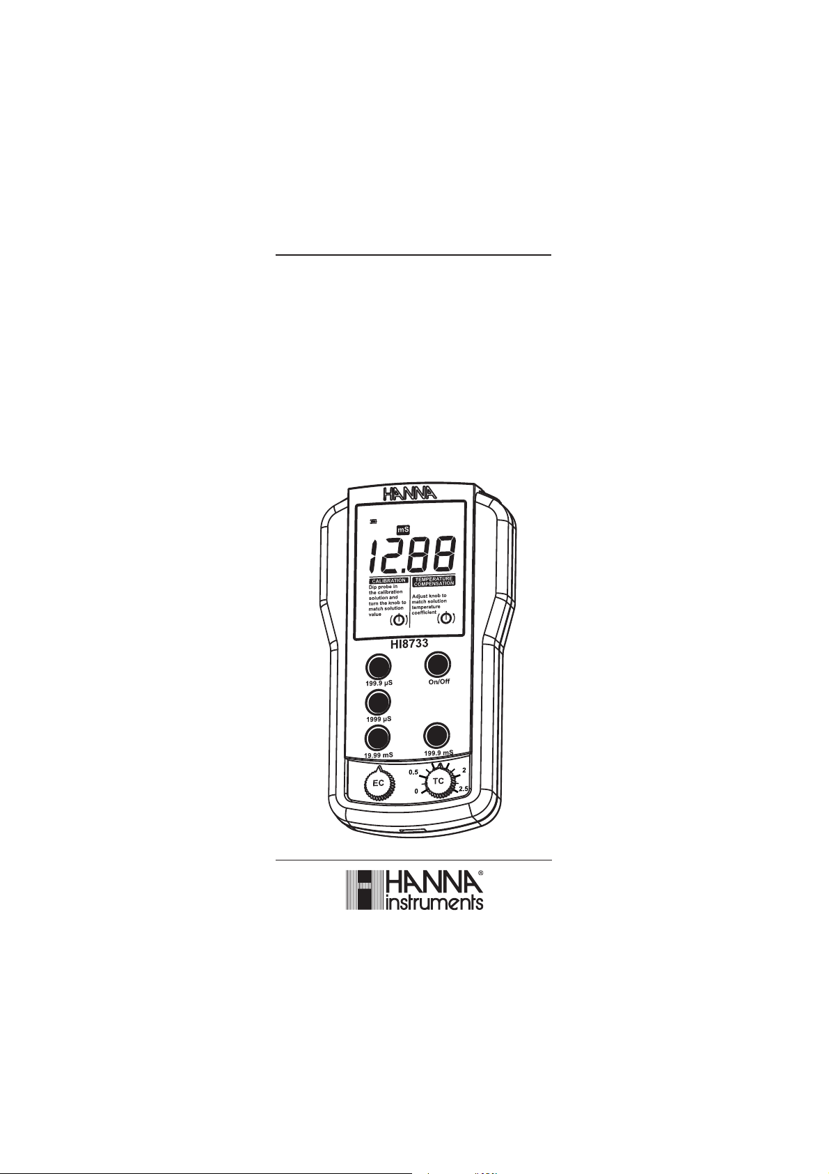
HI 8633
HI 8733 - HI 8734
Reliable and Waterproof
Multi-Range
Conductivity Meters
www.hannainst.com
1
Page 2

Dear Customer,
Thank you for choosing a Hanna Instruments product.
Please read this instruction manual carefully before using these instruments.
This manual will provide you with the necessary information for correct
use of these instruments, as well as a precise idea of their versatility.
If you need additional technical information, do not hesitate to e-mail
us at tech@hannainst.com or view our worldwide contact list at
www.hannainst.com.
WARRANTYWARRANTY
WARRANTY
WARRANTYWARRANTY
HI 8633, HI 8733 and HI 8734 are guaranteed for two years
against defects in workmanship and materials when used for their
intended purpose and maintained according to instructions. Electrodes
and probes are guaranteed for six months. This warranty is limited to
repair or replacement free of charge.
Damage due to accidents, misuse, tampering or lack of prescribed
maintenance is not covered.
If service is required, contact the dealer from whom you purchased
the instrument. If under warranty, report the model number, date
of purchase, serial number and the nature of the problem. If the
repair is not covered by the warranty, you will be notified of the
charges incurred. If the instrument is to be returned to Hanna
Instruments, first obtain a Returned Goods Authorization number
from the Technical Service department and then send it with shipping
costs prepaid. When shipping any instrument, make sure it is properly
packed for complete protection.
TABLE OF CONTENTS
WARRANTY ...................................................................................... 2
PRELIMINARY EXAMINATION ........................................................... 3
GENERAL DESCRIPTION ................................................................... 3
FUNCTIONAL DESCRIPTION & SPECIFICATIONS OF HI 8633 .......... 4
FUNCTIONAL DESCRIPTION & SPECIFICATIONS OF HI 8733 .......... 5
FUNCTIONAL DESCRIPTION & SPECIFICATIONS OF HI 8734 .......... 6
OPERATIONAL GUIDE....................................................................... 7
CALIBRATION ................................................................................... 9
CONDUCTIVITY VERSUS TEMPERATURE CHART .............................. 13
TDS VERSUS TEMPERATURE CHART ............................................... 14
DETERMINING THE TEMPERATURE COEFFICIENT OF A SOLUTION (HI 8733) . 15
BATTERY REPLACEMENT ................................................................. 16
PROBE MAINTENANCE ................................................................... 17
ACCESSORIES ................................................................................. 18
2
Page 3

PRELIMINARY EXAMINATION
Remove the instrument from the packing material and examine it
carefully to make sure that no damage has occurred during shipping.
If there is any noticeable damage, notify your Dealer or the nearest
Hanna office immediately.
Each meter is supplied with:
• Conductivity probe with DIN connector and 1 m (3.3') cable:
• HI 76301D for HI 8633 and HI 8734
• HI 76302W for HI 8733
• Calibration solution sachet
• Instruction manual
• 1 x 9V alkaline battery
Note: Save all packing materials until you are sure that the
instrument functions correctly. Any damaged or defective item
must be returned in its original packing materials together
with the supplied accessories.
GENERAL DESCRIPTION
HI 8633 and HI 8733 have been designed specifically for use in the areas
of production and quality control. It is often necessary to test samples with
different concentrations ranging from deionized water to brine.
Both models can be manually calibrated at 1 point.
The HI 8733, with a built-in temperature sensor and Automatic
Temperature Compensation, is the perfect instrument for measuring
samples with fluctuating temperature.
HI 8734 has been specially designed for the water conditioning industry,
particularly in the softening, demineralization, reverse osmosis and
drinking water applications.
Three ranges of measurement assure the highest accuracy possible. In
addition, Manual Temperature Compensation is possible through a knob
on the front panel.
The ratio between conductivity and TDS is factory set at 0.5.
Moreover, the 4-ring potentiometric probes supplied with the meters are
made of rugged PVC - ideal for indoor, as well as outdoor measurements.
All rights are reserved. Reproduction in whole or in part is prohibited
without the written consent of the copyright owner.
3
Page 4
egnaR
9991ot0/9.991ot0.0
µ mc/S
mc/Sm9.991ot0.0/99.91ot00.0
noituloseR
1/1.0
µ mc/S
mc/Sm1.0/10.0
ycaruccA
)F°86/C°02@(
elacslluF%1±
rorreeborpgnidulcxe
noitaiveDCMElacipyT elacSlluF%2±
noitarbilaC bonkCEhguorht,tniop1,launaM
erutarepmeT
noitasnepmoC
)F°221ot23(C°05ot0,launaM
htiw
β C°/%2=
)dedulcni(eborP D10367IH elbac)'3.3(m1htiw
tnemnorivnE %001xamHR;)F°221ot23(C°05ot0
epyTyrettaB enilaklaV9x1
efiLyrettaB esuesuounitnocfosruoh001.xorppA
snoisnemiD )"4.1x1.3x7.5(mm63x08x541
thgieW ).zo1.8(g032
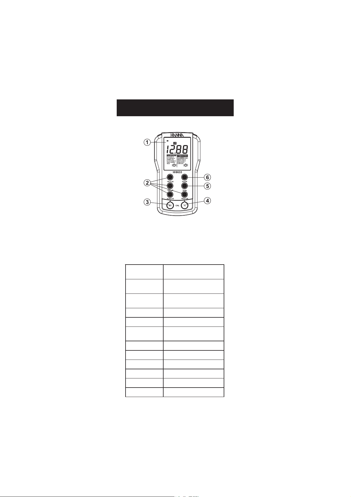
FUNCTIONAL DESCRIPTION &
SPECIFICATIONS OF HI 8633
1) Liquid Crystal Display
2) Measurement range selection keys
3) EC calibration knob
4) Manual temperature compensation knob
5) Temperature selection key
6) On/Off key
4
Page 5
egnaR
9991ot0/9.991ot0.0
µ mc/S
mc/Sm9.991ot0.0/99.91ot00.0
noituloseR
1/1.0
µ mc/S
mc/Sm1.0/10.0
ycaruccA
)F°86/C°02@(
elacslluF%1±
rorreeborpgnidulcxe
noitaiveDCMElacipyT elacSlluF%2±
noitarbilaC bonkCEhguorht,tniop1,launaM
erutarepmeT
noitasnepmoC
)F°221ot23(C°05ot0,citamotuA
htiw
β C°/%5.2ot0morfelbatsujda
)dedulcni(eborP W20367IH elbac)'3.3(m1htiwCTA
tnemnorivnE %001xamHR;)F°221ot23(C°05ot0
epyTyrettaB enilaklaV9x1
efiLyrettaB esuesuounitnocfosruoh001.xorppA
snoisnemiD )"4.1x1.3x7.5(mm63x08x541
thgieW ).zo1.8(g032
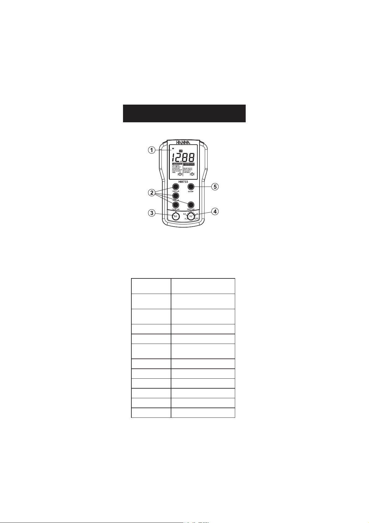
FUNCTIONAL DESCRIPTION &
SPECIFICATIONS OF HI 8733
1) Liquid Crystal Display
2) Measurement range selection keys
3) EC calibration knob
4) Automatic Temperature Compensation coefficient knob
5) On/Off key
5
Page 6
egnaR
L/gm9991ot0/9.991ot0.0
L/g99.91ot00.0
noituloseR
L/gm1/1.0
L/g10.0
ycaruccA
)F°86/C°02@(
elacslluF%1±
rorreeborpgnidulcxe
noitaiveDCMElacipyT elacSlluF%2±
noitarbilaC bonkSDThguorht,tniop1,launaM
erutarepmeT
noitasnepmoC
)F°221ot23(C°05ot0,launaM
htiw
β C°/%2=
rotcafSDT 5.0
)dedulcni(eborP D10367IH elbac)'3.3(m1htiw
tnemnorivnE %001xamHR;)F°221ot23(C°05ot0
epyTyrettaB enilaklaV9x1
efiLyrettaB esuesuounitnocfosruoh001.xorppA
snoisnemiD )"4.1x1.3x7.5(mm63x08x541
thgieW ).zo1.8(g032
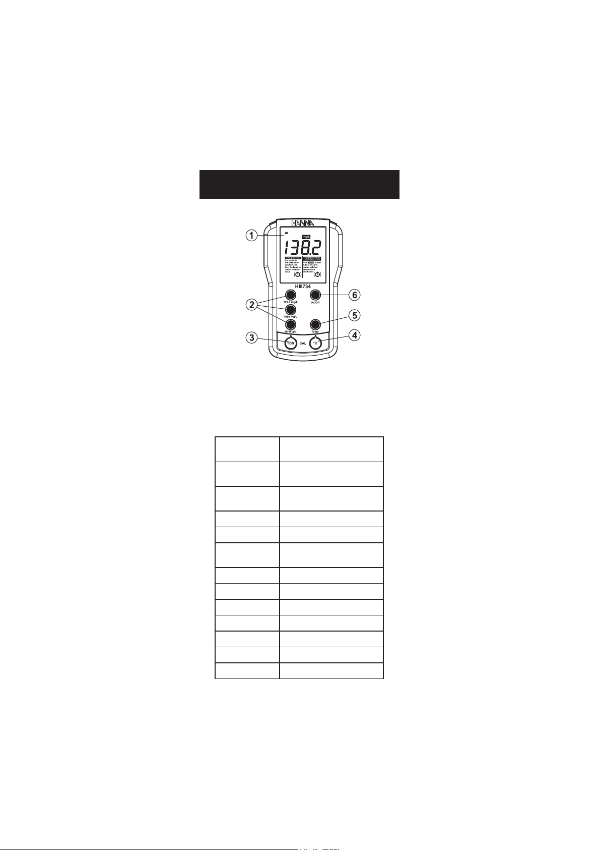
FUNCTIONAL DESCRIPTION &
SPECIFICATIONS OF HI 8734
1) Liquid Crystal Display
2) Measurement range selection keys
3) TDS calibration knob
4) Manual temperature compensation knob
5) Temperature selection key
6) On/Off key
6
Page 7

OPERATIONAL GUIDE
• Each meter is supplied complete with a 9V battery. Remove the
battery compartment cover on the back of the meter (see
page 16). Install the battery while observing its polarity.
• Connect the probe to the meter securely
by aligning the pins with the socket
and pushing the plug in.
• Make sure that the meter has been
calibrated before taking any measurements (see “Calibration”
section).
• Immerse the conductivity probe into
the sample, with the holes on the
shaft completely submerged.
If possible, use plastic beakers or containers
to minimize any EMC interference.
• Tap the probe lightly on the bottom of the beaker to remove any
air bubbles which may be trapped inside the PVC sleeve.
• Turn the instrument on by pressing the On/Off key.
For HI 8633 and HI 8734:
• Take the temperature of the solution
with a ChecktempC or another accurate
thermometer following LCD indication.
• Press and hold down the Temp key to display the temperature
and adjust the temperature knob to that of the solution e.g.
20°C.
For HI 8733:
• Adjust the TEMPERATURE COEFFICIENT
knob to 2% to compensate for the
temperature effect of average solutions
(to determine exact value for a particular
solution, see page 15).
• Select the appropriate measurement range.
7
Page 8

Note: If the display shows only a “1” on the
far left hand side, the meter is out of
range. Select the next (higher) range.
• Wait for a couple of minutes for the temperature sensor to reach
thermal equilibrium with the sample before taking measurements.
• After the measurement has been completed, the instrument
should be switched off and the probe should be cleaned and
dried (see “Probe Maintenance” on page 17).
8
Page 9

CALIBRATION
Accessories needed:
• Use any calibration solution within the meter’s range. The
solution should ideally be close to the samples being
measured. Use for example HI 7030 or HI 8030, 12880 µS/cm
(=12.88 mS/cm) conductivity solution, for HI 8633 and
HI 8733, and HI 7032, 1382 mg/L (=2764 µS/cm) TDS
solution, for HI 8734.
• ChecktempC or another accurate thermometer with 0.1°C
resolution (not necessary for HI 8733).
PROCEDURE FOR HI 8633 AND HI 8734
• Pour sufficient quantity of a conductivity
(HI 8633) or TDS (HI 8734) calibration
solution (e.g. HI 7030 or HI 7032) into a
beaker to cover the holes on the probe. If
possible, use plastic beakers to minimize
any EMC interference.
• Immerse the conductivity probe, making
sure that holes are completely submerged,
and the ChecktempC in the solution.
• Wait for a couple of minutes for thermal
equilibrium to be reached.
• Tap the probe on the bottom, then shake it while rotating to
make sure no air bubbles remain trapped in the sleeve.
• Record the temperature of the buffer solution from the thermometer
(e.g. 20°C).
• Switch the instrument on by pressing On/Off.
9
Page 10

• Press and hold down Temp to display the
temperature.
• Adjust the TEMPERATURE knob to display 20°C.
• Release Temp key to display conductivity measurement.
• Select 19.99 mS/cm (HI 8633)
or 1999 mg/L (HI 8734) range
by pressing the appropriate
range key.
• Follow LCD calibration indication. Adjust the calibration knob until
the display shows for HI 8633 the conductivity reading at 25°C
(see the conductivity vs. temperature table), e.g. @ 25°C,
12880 µS/cm = 12.88 mS/cm, or for HI 8734 the TDS
reading at 25°C (see the TDS vs. temperature chart), e.g.
@25°C, 1382 mg/L.
• All subsequent measurements will be compensated to 25°C (77°F).
If you prefer to standardize the temperature compensation to
20°C (68°F) rather than 25°C (77°F), leave the TEMPERATURE
knob at 18°C (if the temperature of the solution is 18°C), adjust
the knob to read “11.67 mS” (see the conductivity vs. tempera-
ture chart) or “1251 mg/L” (see the TDS vs. temperature chart). All
subsequent measurements will be compensated to 20°C.
• The calibration is now complete and the instrument is ready for
use.
10
Page 11

The instrument should be recalibrated at least once a month, or
when the probe is changed.
Note: For more accurate results, it is advisable to use a calibration
solution close to the measurement range. See the “Accessories”
section for a wide selection of conductivity solutions.
PROCEDURE FOR HI 8733
• Pour sufficient quantity of a conductivity
calibration solution (e.g. HI 7030/
HI 8030) into a beaker to cover the
holes on the probe. If possible, use
plastic beakers to minimize any EMC
interference.
• Immerse the conductivity probe in the
solution, making sure that holes are
completely submerged.
• Wait for a couple of minutes for thermal
equilibrium to be reached.
• Tap the probe on the bottom, then
shake it while rotating to make sure no
air bubbles remain trapped in the
sleeve.
• Switch the instrument on by pressing
On/Off.
• Set the temperature coefficient knob to
2% to compensate for the temperature
effect of average solutions (to determine
exact value for a particular solution,
see page 15).
• Select 19.99 mS/cm range by pressing
the appropriate range key.
11
Page 12

• Follow LCD calibration indication. Adjust the calibration knob
until the display shows “12.88 mS” i.e. the conductivity reading
@ 25°C.
• All subsequent measurements will be compensated to 25°C (77°F).
If you prefer to standardize the temperature compensation to
20°C (68°F) rather than 25°C (77°F), adjust the knob to read
“11.67 mS” (see the conductivity vs. temperature chart on page 13).
All subsequent measurements will be compensated to 20°C.
• The calibration is now complete and the instrument is ready for
use.
The instrument should be recalibrated at least once a month, or
when the probe is changed.
Note: For more accurate results, it is advisable to use a calibration
solution close to the range to be measured. See the “Accessories”
section for a wide selection of conductivity solutions.
12
Page 13

Cº Fº
0307IH
0308IH
(
µ )mc/S
1307IH
1308IH
(
µ )mc/S
3307IH
3308IH
(
µ )mc/S
4307IH
4308IH
(
µ )mc/S
5307IH
5308IH
(
µ )mc/S
9307IH
9308IH
(
µ )mc/S
0 23 0517 677 46 00384 00456 0672
5 14 0228 698 56 00535 00147 0813
01 05 0339 0201 76 00695 00238 5163
51 95 08401 7411 86 00456 00529 3604
61 8.06 02701 3711 07 00276 00449 5514
71 6.26 05901 9911 17 00586 00369 5424
81 4.46 09111 5221 37 00896 00289 7334
91 2.66 03411 1521 47 00317 002001 9244
02 86 07611 8721 67 00427 001201 3254
12 8.96 01911 5031 87 00047 000401 7164
22 6.17 05121 2331 97 00257 009501 1174
32 4.37 09321 9531 18 00567 009701 5084
42 2.57 04621 6831 28 00387 008901 2094
52 77 08821 3141 48 00008 008111 0005
62 8.87 03131 0441 68 00318 008311 6905
72 6.08 07331 7641 78 00038 007511 0915
82 4.28 02631 4941 98 00948 007711 6825
92 2.48 07831 1251 09 00368 007911 3835
03 68 02141 8451 29 00288 008121 9745
13 8.78 07341 5751 49 00009 009321 5755
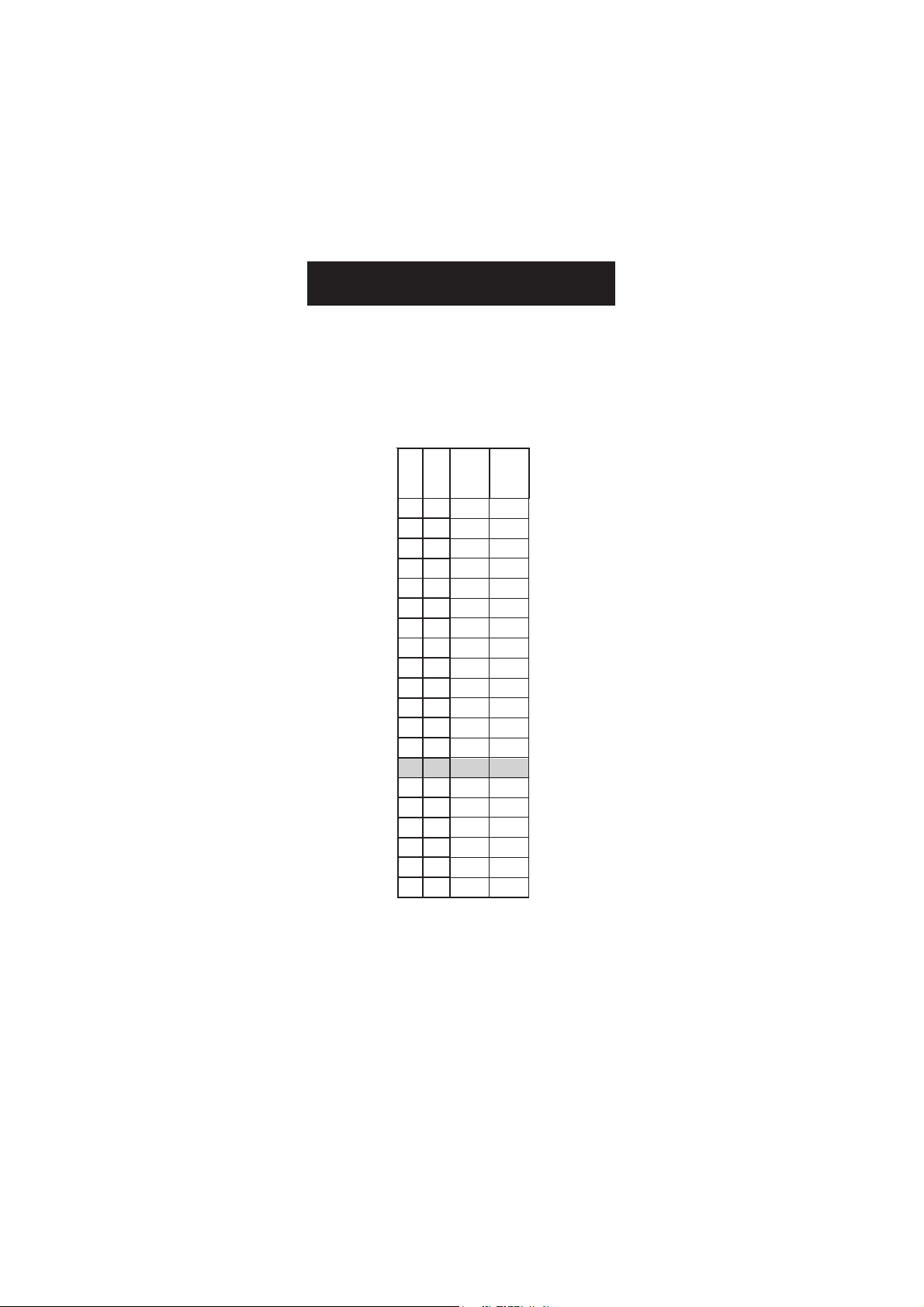
CONDUCTIVITY VERSUS
TEMPERATURE CHART
The conductivity of an aqueous solution is the measure of its ability to
carry an electrical current by means of ionic motion.
The conductivity invariably increases with increasing temperature.
It is affected by the type and number of ions in the solution and by
the viscosity of the solution itself. Both parameters are temperature
dependent. The dependency of conductivity on temperature is
expressed as a relative change per degree Celsius at a particular
temperature, commonly as percent per °C.
For manual temperature compensation, refer to the following chart:
For instance, the conductivity values of the calibration solutions at
25°C are 12880 µS/cm, 1413 µS/cm or 5000 µS/cm when using
HI 7030, HI 7031 or HI 7039, respectively.
At 20°C, the values are 11670 µS/cm, 1278 µS/cm or
4523 µS/cm, respectively.
With the solutions at 30°C, the values are 14120 µS/cm, 1548 µS/cm
or 5479 µS/cm, respectively.
13
Page 14
Cº Fº
2307IH
L/gm
)mpp(
6307IH
L/g
)tpp(
0 23 857 28.6
5 14 678 88.7
01 05 999 99.8
51 95 2211 01.01
61 8.06 8411 33.01
71 6.26 3711 65.01
81 4.46 0021 87.01
91 2.66 4221 10.11
02 86 1521 42.11
12 8.96 7721 74.11
22 6.17 3031 17.11
32 4.37 9231 49.11
42 2.57 8531 81.21
52 77 2831 14.21
62 8.87 8041 56.21
72 6.08 8341 98.21
82 4.28 1641 31.31
92 2.48 6741 73.31
03 68 5151 16.31
13 8.78 1451 58.31
TDS VERSUS
TEMPERATURE CHART
The TDS value in aqueous solutions is directly proportional to
conductivity. The ratio between the two parameters depends on the
solution and usually it is set to a factor of 0.5 (corresponding to a
solution of CaCO
(ppm) of TDS.
For manual temperature compensation, refer to the following chart:
). This means that 1 µS/cm is equal to 0.5 mg/L
3
For instance, the TDS values of the calibration solutions at 25°C are
1382 mg/L or 12.41 g/L when using HI 7032 or HI 7036,
respectively.
At 20°C, the values are 1251 mg/L or 11.24 g/L, respectively.
With the solutions at 30°C, the values are 1515 mg/L or 13.61 g/L,
respectively.
14
Page 15

DETERMINING THE TEMPERATURE
COEFFICIENT OF A SOLUTION (HI 8733)
Highly acidic, alkaline samples or solutions with high salt content
might have a different coefficient than the customary 2% per degree °C.
In order to calculate this coefficient follow the procedure below:
• Immerse the probe of HI 8733 in the sample and adjust the
TEMPERATURE COEFFICIENT knob to 0% (i.e. no compensation).
• Condition the sample and probe to 25°C and note the conductivity
reading, C25.
• Condition the sample and probe to a different temperature t°C
(approximately 10°C different from 25°C) and note the conductivity
reading Ct.
• The temperature coefficient β of the solution is calculated as given
by the following formula:
β = 100 x
The above procedure is suitable for determining the temperature
coefficient in a laboratory or where the temperature of the solution
can be controlled.
If this is not possible (e.g. on-site measurements), the following
procedure can be used providing the sample temperature varies by at
least 5°C or preferably 10°C:
• Immerse the probe of HI 8733 in the test solution and turn the
TEMPERATURE COEFFICIENT knob to 0% (no compensation).
• Check the conductivity reading and record the value. Make sure
the reading is stable, i.e. no greater variations than ±0.2 mS/cm
within a minute.
• Repeat the procedure when the temperature of the test solution
has changed by at least 5°C. Wait for the conductivity reading to
stabilize.
• Adjust the TEMPERATURE COEFFICIENT knob until the display
shows the same value as recorded earlier.
• The value indicated by the knob is the temperature coefficient of
the solution.
(Ct - C25)
(t - 25) x C
25
15
Page 16

BATTERY REPLACEMENT
When battery becomes weak the meter will display the battery symbol
as empty.
When the low battery indicator appears, the battery has only a few
hours left. A low battery will result in unreliable measurements.
It is recommended to replace the battery immediately.
Battery replacement must only take place in a nonhazardous area
using a 9V alkaline battery.
Unscrew the three screws on the rear of the meter, remove the battery
compartment cover and replace the 9V battery with a new one.
Make sure the battery contacts are tight and secure before replacing
the cover.
16
Page 17

PROBE MAINTENANCE
Rinse the probe with tap
water after every series of
measurements. If a more
thorough cleaning is required,
remove the PVC sleeve and
clean the probe with a cloth
or a nonabrasive detergent.
When reinserting the sleeve
onto the probe, be sure that
the sleeve is in the right
direction with the four holes
towards the cable end.
After cleaning the probe,
recalibrate the instrument.
The probe body is in PVC.
For this reason it must never
come into close contact with
a heat source. If the probe is
exposed to high temperatures
(above 50°C/122°F), the
rings might become loose
or detached, resulting in a
serious impairment of the
probe. In such cases, the
probe has to be replaced.
17
Page 18

ACCESSORIES
CALIBRATION SOLUTIONS
HI 7030L 12880 µS/cm, 500 mL bottle
HI 7030M 12880 µS/cm, 230 mL bottle
HI 7031L 1413 µS/cm, 500 mL bottle
HI 7031M 1413 µS/cm, 230 mL bottle
HI 7033L 84 µS/cm, 500 mL bottle
HI 7033M 84 µS/cm, 230 mL bottle
HI 7034L 80000 µS/cm, 500 mL bottle
HI 7034M 80000 µS/cm, 230 mL bottle
HI 7035L 111800 µS/cm, 500 mL bottle
HI 7035M 111800 µS/cm, 230 mL bottle
HI 7039L 5000 µS/cm, 500 mL bottle
HI 7039M 5000 µS/cm, 230 mL bottle
HI 7032L 1382 ppm (mg/L), 500 mL bottle
HI 7032M 1382 ppm (mg/L), 230 mL bottle
HI 7036L 12.41 ppt (g/L), 500 mL bottle
HI 7036M 12.41 ppt (g/L), 230 mL bottle
CONDUCTIVITY PROBES
HI 76301D Conductivity probe with 1m (3.3') cable and DIN
connector
HI 76302W Conductivity probe with built-in temperature sensor,
1m (3.3') cable and DIN connector
OTHER ACCESSORIES
HI 98501 Electronic thermometer (range: -50.0 to 150.0°C)
HI 710007 Shockproof rubber boot, blue
HI 710008 Shockproof rubber boot, orange
HI 710050 Spare protective case
18
Page 19

RECOMMENDATIONS FOR USERS
Before using these products, make sure they are entirely suitable for
the environment in which they are used.
Operation of these instruments in residential areas could cause
unacceptable interferences to radio and TV equipment, requiring the
operator to follow all necessary steps to correct interferences.
The metal band at the end of the probe is sensitive to electrostatic
discharges. Avoid touching this metal band at all times.
During operation, ESD wrist straps should be worn to avoid possible
damage to the probe by electrostatic discharges.
Any variation introduced by the user to the supplied equipment may
degrade the instruments’ EMC performance.
To avoid electrical shock, do not use these instruments when voltages
at the measurement surface exceed 24 VAC or 60 VDC.
Use plastic beakers to minimize any EMC interferences.
To avoid damage or burns, do not perform any measurement in
microwave ovens.
Hanna Instruments reserves the right to modify the design, construction and
appearance of its products without advance notice.
19
Page 20

Hanna Instruments Inc.
Highland Industrial Park
584 Park East Drive
Woonsocket, RI 02895 USA
Technical Support for Customers
Tel. (800) 426 6287
Fax (401) 765 7575
E-mail tech@hannainst.com
www.hannainst.com
Local Sales and Customer Service Office
Printed in EUROPE
(ROMANIA)
MAN8734Y 07/10
20
 Loading...