

Page 1
Instruction Manual
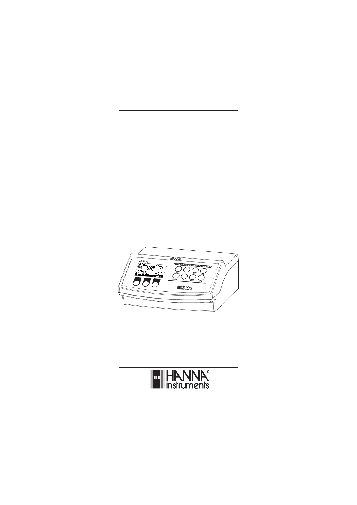
HI 3512
Two Channels
pH/ORP/ISE,
EC/TDS/NaCl/Resistivity,
Temperature
Bench Meter
www.hannainst.com
1
Page 2

Dear Customer,
Thank you for choosing a Hanna Instruments product.
Please read this instruction manual carefully before using this instrument.
This manual will provide you with the necessary information for correct use
of this instrument, as well as a precise idea of their versatility.
If you need additional technical information, do not hesitate to e-mail us
at tech@hannainst.com or view our worldwide contact list at
www.hannainst.com.
WARRANTYWARRANTY
WARRANTY
WARRANTYWARRANTY
The HI 3512 is guaranteed for two years against defects in workmanship
and materials when used for their intended purpose and maintained
according to instructions. Electrodes and probes are guaranteed for six
months. This warranty is limited to repair or replacement free of charge.
Damage due to accidents, misuse, tampering or lack of prescribed
maintenance is not covered.
If service is required, contact the dealer from whom you purchased the
instrument. If under warranty, report the model number, date of purchase,
serial number and the nature of the problem. If the repair is not covered
by the warranty, you will be notified of the charges incurred. If the
instrument is to be returned to Hanna Instruments, first obtain a
Returned Goods Authorization number from the Technical Service
department and then send it with shipping costs prepaid. When shipping
any instrument, make sure it is properly packed for complete protection.
TABLE OF CONTENTSTABLE OF CONTENTS
TABLE OF CONTENTS
TABLE OF CONTENTSTABLE OF CONTENTS
WARRANTY ................................................................................................................................ 2
PRELIMINARY EXAMINATION ....................................................................................................... 3
GENERAL DESCRIPTION ............................................................................................................... 3
FUNCTIONAL DESCRIPTION ........................................................................................................ 5
SPECIFICATIONS ........................................................................................................................7
OPERATIONAL GUIDE .............................................................................................................. 10
AUTO-RANGING EC CHANNEL .................................................................................................... 15
TEMPERATURE COMPENSATION EC CHANNEL ............................................................................. 16
CONDUCTIVITY VERSUS TEMPERATURE CHART ............................................................................ 17
USER CALIBRATION ................................................................................................................. 18
pH CALIBRATION .................................................................................................................... 19
pH BUFFER TEMPERATURE DEPENDENCE ................................................................................... 27
RELATIVE mV CALIBRATION ..................................................................................................... 28
ISE CALIBRATION ................................................................................................................... 29
EC CALIBRATION .................................................................................................................... 33
GOOD LABORATORY PRACTICE (GLP) .......................................................................................... 37
SETUP ................................................................................................................................... 40
LOGGING ................................................................................................................................ 55
mV CALIBRATION (for technical personnel only) ......................................................................... 58
TEMPERATURE CALIBRATION (for technical personnel only) .......................................................... 59
PC INTERFACE ........................................................................................................................ 61
TEMPERATURE CORRELATION FOR pH SENSITIVE GLASS ............................................................... 71
ELECTRODE CONDITIONING & MAINTENANCE ............................................................................ 72
EC PROBE MAINTENANCE ........................................................................................................ 75
TROUBLESHOOTING GUIDE ..................................................................................................... 76
ACCESSORIES ......................................................................................................................... 77
2
Page 3

PRELIMINARY EXAMINATIONPRELIMINARY EXAMINATION
PRELIMINARY EXAMINATION
PRELIMINARY EXAMINATIONPRELIMINARY EXAMINATION
Remove the instrument from the packing material and examine it carefully
to make sure that no damage has occurred during shipping. If there is any
damage, notify your Dealer or the nearest Hanna Customer Service Center.
Each instrument is supplied with:
• HI 1131B Glass body combination double-junction pH electrode
• HI 76310 Four Ring Conductivity Probe with built-in temperature
• HI 7662 -T stainless steel Temperature Probe with 1 m (3.3') Cable
• HI 70004 pH 4.01 Buffer Solution (20 mL sachet)
• HI 70007 pH 7.01 Buffer Solution (20 mL sachet)
• HI 700661 Cleaning solution (2x20 mL each)
• HI 7071S Electrolyte Solution
• HI 76404N Electrode Holder
• 12 Vdc Power Adaptor
• Instruction Manual
HI 3512 is supplied with 12 Vdc/230 Vac power adapter
HI 3512-01 is supplied with 12 Vdc/115 Vac power adapter
Note: Save all packing material until you are sure that the instrument
functions correctly. All defective items must be returned in the
original packing with the accessories supplied.
GENERAL DESCRIPTIONGENERAL DESCRIPTION
GENERAL DESCRIPTION
GENERAL DESCRIPTIONGENERAL DESCRIPTION
The HI 3512 instrument is state-of-the-art, professional bench meter
with graphical LCD, designed to provide laboratory results and accuracy.
Two input channels are available.
• Channel 1: pH/mV/ISE and temperature
• Channel 2: EC/TDS, NaCl/Resistivity and temperature
HI 3512 is provided with a series of new diagnostic features which add
an entirely new dimension to the measurement of pH and EC, by allowing
the user to dramatically improve the reliability of the measurement:
pH channel:
• 7 standard pH buffers (pH 1.68, 4.01, 6.86, 7.01, 9.18, 10.01
and 12.45) for calibration.
• pH calibration up to five calibration points (see instrument specifications).
• Custom calibration with up to two custom buffers.
• Messages on the graphic LCD for an easy and accurate calibration.
• Diagnostic features to alert the user when the electrode needs cleaning.
• User selectable “Out of cal. range“ warning.
• User selectable “Calibration Timeout“ to remind when a new
calibration is necessary.
3
Page 4

• Extended temperature range on pH channel from –20 to 120 ºC
(–4 to 248 ºF), using HI 7662-T interchangeable temperature
probes.
EC channel:
• 7 memorized standards (0.00 µS/cm, 84.0 µS/cm, 1.413 mS/cm,
5.00 mS/cm, 12.88 mS/cm, 80.0 mS/cm and 111.8 mS/cm) for
calibration.
• EC calibration up to two calibration points.
• Messages on the graphic LCD for an easy and accurate calibration.
• Diagnostic features to alert the user when the electrode needs cleaning.
• User selectable “Out of cal. range” warning.
• User selectable “Calibration Timeout” to remind when a new
calibration is necessary.
• Extended temperature range on EC channel from –20 to 120 ºC
(–4 to 248 ºF), using temperature sensor inside EC probe.
• Temperature compensation selection
• Temperature reference selection 15 °C, 20 °C or 25 °C.
• Temperature coefficient set
• Lock and user setup Fixed range selection
Other features include:
• Log on demand up to 400 samples
• Log interval with log on stability feature up to 600 records
• Auto Hold feature, to freeze first stable reading on the LCD
• GLP feature, to view last calibration data for pH, Rel mV, ISE, EC or
NaCl.
• PC interface
This instrument can also measure with ORP electrodes (pH channel
input), thanks to their capability to measure mV with a resolution up to
0.1 mV and with ISE electrodes on ppm scale (pH channel input). The
electrode type and unit selection capability and the ISE calibration in up
to five calibration standard solutions make this instrument very useful
for a large range of concentration solutions measurements.
Relative mV feature is also available.
This instrument can also measure in Resistivity, TDS and Salinity on EC
channel.
4
Page 5
FUNCTIONAL DESCRIPTIONFUNCTIONAL DESCRIPTION
FUNCTIONAL DESCRIPTION
FUNCTIONAL DESCRIPTIONFUNCTIONAL DESCRIPTION
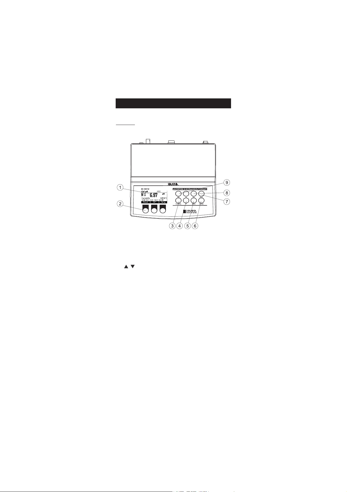
Front view
1) Liquid Crystal Display (LCD)
2) Function keys
3) CHANNEL keys to toggle between channels (Ch1 - pH, Ch2 - EC)
4) / keys to manually increase/decrease the parameters or to scroll
between the parameter list
5) MENU key, to change the function key at the bottom of the display
6) RANGE key, to switch between pH, mV and ISE range (Ch1); EC, Resitivity,
TDS and Salinity range (Ch2)
7) HELP key to enter/exit contextual help
8) CAL key, to enter calibration mode
9) ESC to escape the current mode, exit calibration, setup, help, etc.
5
Page 6
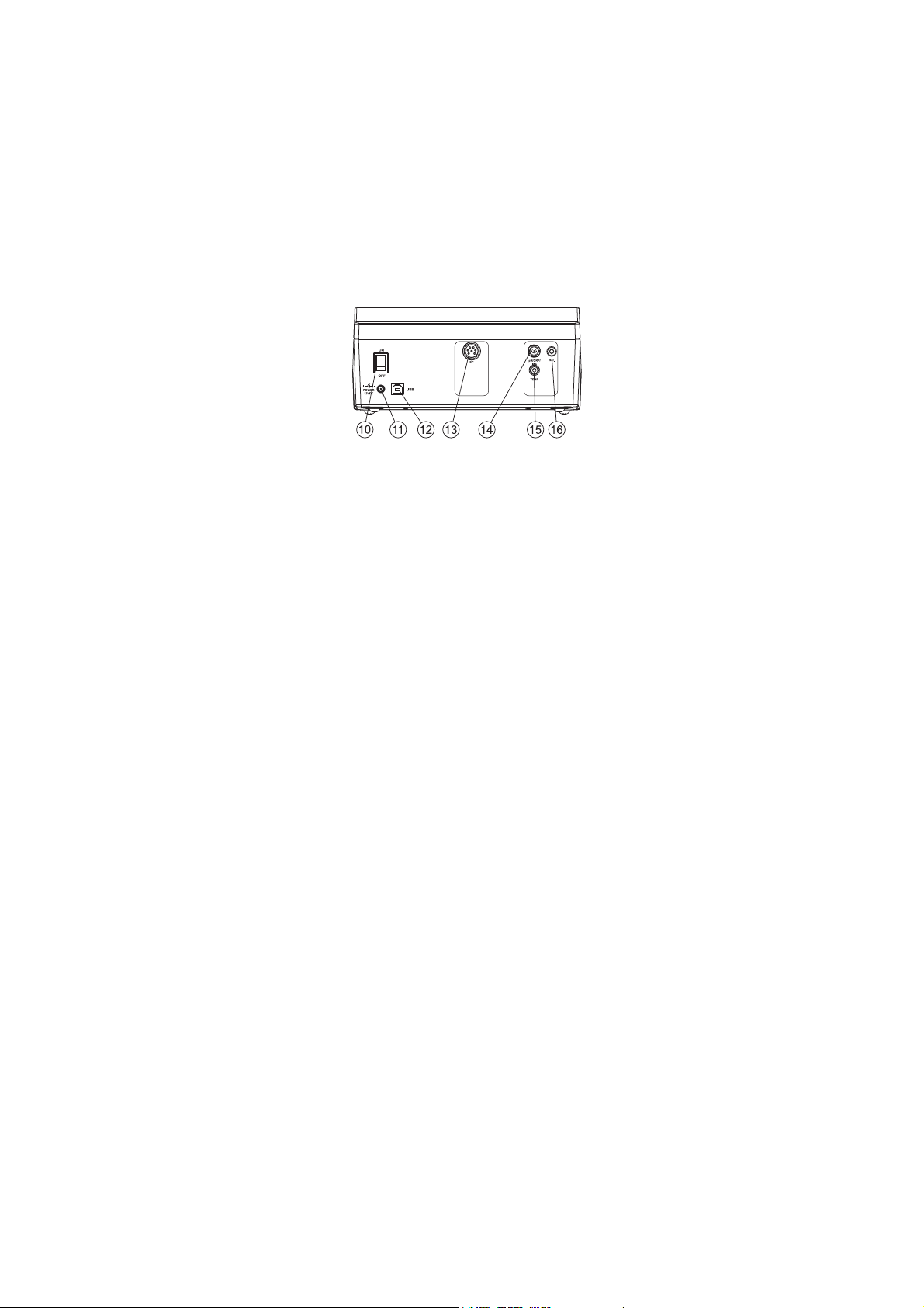
Rear view
10) ON/OFF switch.
11) Power adaptor socket.
12) USB connector.
13) DIN connector for EC probe.
14) BNC electrode connector for pH/ORP, ISE electrode.
15) Temperature socket for pH/ORP, ISE channel.
16) Reference electrode connector for pH/ORP, ISE channel.
6
Page 7
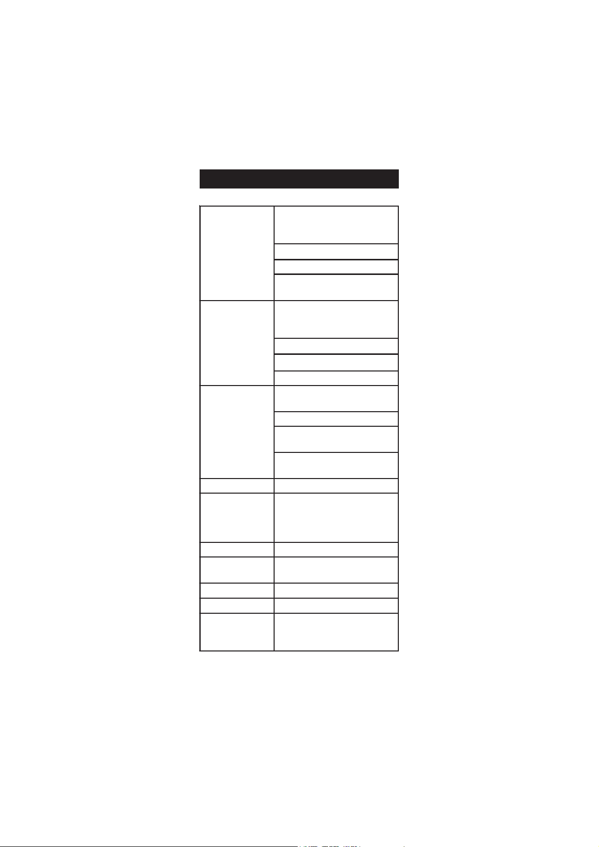
egnaR
Hp0.02ot0.2–
Hp00.02ot00.2–
Hp000.02ot000.2–
Vm0.0002±
.cnoc01E99.9ot7-E00.1
)Fº0.842ot0.4(Cº0.021ot0.02–
1lennahC
noituloseR
00 Hp1.0
0 Hp10.0
Hp100.0
Vm1.0
.cnoc01,1,1.0,10.0stigid3
)Fº1.0(Cº1.0
ycaruccA
Fº86/Cº02@
Hp10.0±
Hp200.0±
Vm2.0±
)snoitnelavonom(gnidaerfo%5.0±
)snoitnelavid(gnidaerfo%1±
)Fº4.0±(Cº2.0±
)rorreeborpgnidulcxe(
egnartesffoVmleR Vm0002±
noitarbilaCHp
,noitarbilactniop-evifotpU
elbaliavasreffubdradnats7
,)54.21,10.01,81.9,10.7,68.6,10.4,86.1(
sreffubmotsuc2dna
noitarbilaCepolS %011ot08morF
erutarepmeTHp
noitasnepmoC
morfcitamotuArolaunaM
)Fº0.842ot0.4–(Cº0.021ot0.02–
edortcelEHp B1311IH )dedulcni(
eborperutarepmeT T-2667IH )dedulcni(
noitarbilaCESI
.stniopnoitarbilactniop-evifotpU
elbaliavasnoitulosdradnats6
)mpp00001,0001,001,01,1,1.0(
SPECIFICATIONSSPECIFICATIONS
SPECIFICATIONS
SPECIFICATIONSSPECIFICATIONS
7
Page 8

CE
egnaR
00 mc/Sm004ot0
)mc/Sm0001otpuseulavswohs(
mc/Sm0001ytivitcudnoclautcA
mc/Sµ999.9ot100.0
mc/Sµ99.99ot00.01
mc/Sµ9.999ot0.001
mc/Sm999.9ot000.1
mc/Sm99.99ot00.01
. ot0.001 0 mc/Sm9.999
mc/Sm0001
)gnignarotua(
noituloseR
mc/Sµ100.0
0 mc/Sµ10.0
00 mc/Sµ1.0
mc/Sm100.0
0 mc/Sm10.0
00 mc/Sm1.0
.000 mc/Sm1
ycaruccA
gnidaerfo%1±
)retaergrevehcihwtigid1romc/Sµ10.0±(
rorreeborpgnidulcxe
ytivitsiseR
egnaR
0 ot0.1 1 smho9.99
. ot001 .1 smho999
ot00.1
1 smhoK99.9
ot0.01
1 smhoK9.99
. ot001 .1 smhoK999
ot00.1
1 smhoM99.9
smhoM0.001ot0.01
)gnignarotua(
noituloseR
0 mho1.0
.00 mho1
smhoK10.0
0 smhoK1.0
0.0 smhoK1
0 smhoM10.0
0 smhoM1.0
ycaruccA
gnidaerfo%1±
)retaergrevehcihwtigid1rosmho01±(
rorreeborpgnidulcxe
SDT
egnaR
mpp999.9ot000.0
mpp99.99ot00.01
mpp9.999ot0.001
L/g999.9ot000.1
L/g99.99ot00.01
L/g0.004ot0.001
)gnignarotua(
noituloseR
mpp1.0,mpp10.0,mpp100.0
L/g1.0,L/g10.0,L/g100.0
ycaruccA
gnidaerfo%1±
)retaergrevehcihwtigid1rompp50.0±(
rorreeborpgnidulcxe
8
Page 9

ytinilaS
egnaR %0.004ot0.0:lCaN%
noituloseR %1.0
ycaruccA rorreeborpgnidulcxegnidaerfo%1±
erutarepmeT
2lennahC
egnaR C°0.021ot0.02-
noituloseR C°1.0
ycaruccA )rorreeborpgnidulcxe(C°2.0±
noitarbilaCCE
sdradnatsdeziromem7htiwstniop2otpucitamotuA
,mc/Sm00.5,mc/Sm314.1,mc/Sµ0.48,mc/Sµ00.0(
)mc/Sm8.111,mc/Sm0.08,mc/Sm88.21
putestnatsnoclleC 000.01ot010.0
noitarbilaClCaN
ylnotniop1.xaM
htiw( 3707IH ;)dradnats
eborpCE 01367IH
ecruoserutarepmeT
;eborpehtedisnirosnesmorfcitamotuA
yrtnelaunaM
erutarepmeTCE
noitasnepmoC
CTA,CTM,CToN
ecnerefeR
erutarepmeT
C°52,02,51
erutarepmeT
tneicifeoC
C°/%00.01ot00.0
rotcaFSDT 00.1ot04.0
dnamednoGOL selpmas004
gniggoltoL
ces03,01,5
dnEotuA,nim081,021,06,03,51,01,5,2,1
)selpmas006xam(
ecnadepmitupnI 01
21
smho
ylppusrewoP rotpadArewoPcdV21
ecafretniCP detalosi-otpo BSU
snoisnemiD )”33.4x41.8x2.9(mm011x702x532
)ylnoretem(thgieW )bl1.4(gK8.1
tnemnorivnE
)F°221-23(C°05-0
gnisnednoc-non%55HR.xam
9
Page 10
OPERATIONAL GUIDEOPERATIONAL GUIDE
OPERATIONAL GUIDE
OPERATIONAL GUIDEOPERATIONAL GUIDE
POWER CONNECTION
Plug the 12 Vdc adapter into the power supply socket.
Note: This instrument use non volatile memory to retain the pH, mV,
Ion, EC, NaCl calibrations and all other settings, when unplugged.
ELECTRODE AND PROBE CONNECTIONS
For pH, ORP or ISE measurements connect a combination pH/ORP/ISE
electrode to the BNC connector located on the rear panel of the instrument.
For half cell electrodes with a separate reference connect the electrode’s
BNC to the BNC connector and the electrode’s reference to the corresponding
reference input socket.
For temperature measurements and automatic temperature compensation
on pH/ORP/ISE channel, connect the temperature probe to the appropriate
socket.
For EC, TDS, NaCl or Resistivity measurements connect the EC probe to the
DIN connector located on the rear panel of the instrument. As the
channels are fully isolated and a temperature probe is connected on pH
channel you can view independent temperature readings on each channel.
INSTRUMENT START UP
• Turn the instrument ON by pressing ON/OFF switch located on the
rear panel of the instrument.
• At start-up the display will show the Hanna logo for a few
seconds followed by the “Loading Log” message, then enters
the measurement mode.
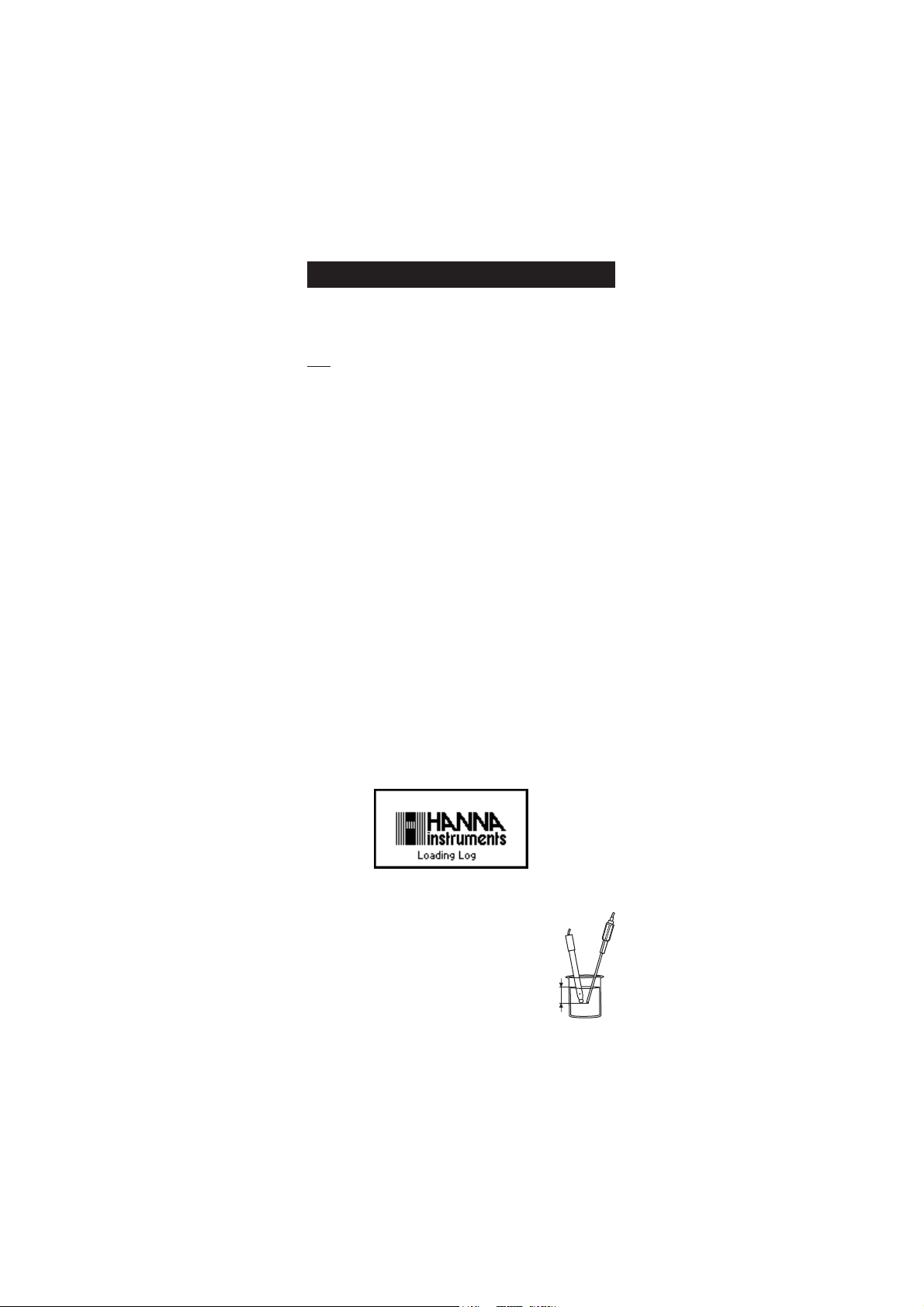
pH MEASUREMENTS
To take a pH measurement remove the electrode
protective cap and simply submerse the electrode and
the temperature probe 3 cm (1¼”) into the sample to
be tested.
If necessary, press CHANNEL to select pH channel
or/and press RANGE until the display changes to
the pH mode. Enter SETUP menu to select the pH resolution.
10
3 cm
Page 11

Allow for the electrode to adjust and reading to stabilize (hourglass
symbol turns off).
On the pH screen are displayed:
• pH reading with the selected resolution.
• Temperature reading in the selected unit (ºC or ºF).
• Temperature compensation mode (MTC - manual, ATC - automatic).
While in MTC mode the indicate that the temperature can be
manually changed using ARROW keys.
• Electrode condition during the calibration day.
• The buffers used in last pH calibration (if feature is enabled in
SETUP).
• Available function keys.
In order to take more accurate pH measurements, make sure that the
instrument is calibrated (see page 19 for details).
It is recommended that the electrode is always kept wet and rinsed
thoroughly with the sample to be measured before use.
The pH reading is directly affected by temperature. For accurate pH
measurements, temperature must be taken into consideration. If the
sample temperature is different from the temperature at which the pH
electrode was kept, allow a few minutes to reach thermal equilibrium.
To use the instrument's Automatic Temperature Compensation feature,
submerse the temperature probe into the sample as close to the electrode
as possible and wait for a few seconds.
If manual temperature compensation (MTC) is desired, the
temperature probe must be disconnected from the instrument.
The display will show the last measured temperature reading, or the last
set temperature, with the “MTC” indication.
The “MTC” indication and the symbol light up on the LCD to indicate
that the instrument is in MTC mode and the ARROW keys can be used
to enter the desired temperature value.
Note: When in MTC mode the user can press and hold an ARROW key,
and the instrument will start incrementing/decrementing the
temperature value. The instrument keeps measuring and the
display is updated periodically.
11
Page 12
ORP MEASUREMENTS
To perform ORP measurements, connect an ORP electrode (see ACCESSORIES
section) to the instrument and turn it ON.
If necessary, enter the mV mode by pressing RANGE
until the display changes to mV.
Submerse the ORP electrode 3 cm (1¼”) into the
3 cm
sample to be tested and wait a few seconds for the
reading to stabilize.
Measurements are displayed with 0.1 mV resolution.
The “ATC” (or “MTC”) message is turned off because mV readings are not
temperature compensated.
For accurate ORP measurements, the surface of the electrode must be
clean and smooth. Pretreatment solutions are available to condition the
electrode and improve its response time (see ACCESSORIES section, page 77).
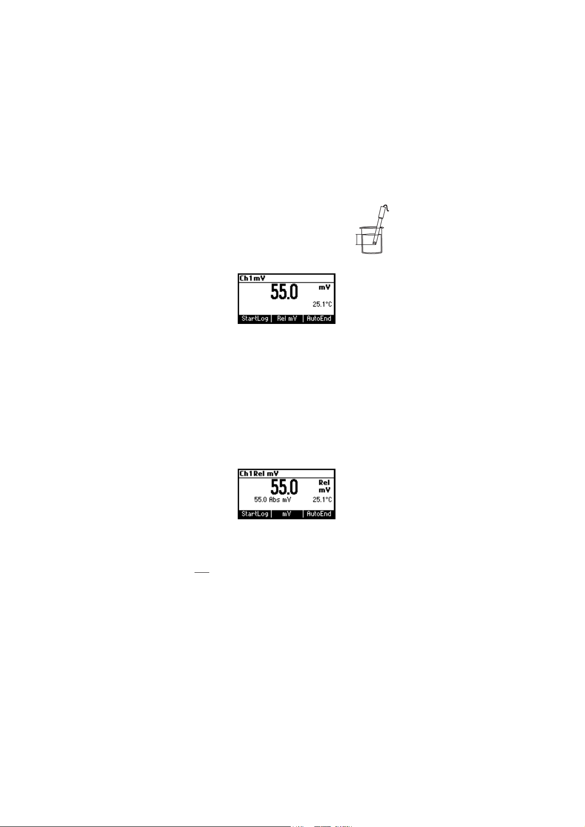
RELATIVE mV MEASUREMENTS
To enter Relative mV mode, press Rel mV function key while in mV
measurement mode. The relative mV reading will be displayed along
with the Absolute mV value and the current temperature readings.
The relative mV reading is equal to the difference between the absolute
mV input value and relative mV offset established in the relative mV
calibration.
Note: If using the pH or ISE electrode while in mV mode, the instrument
will measure the mV generated by the electrode.
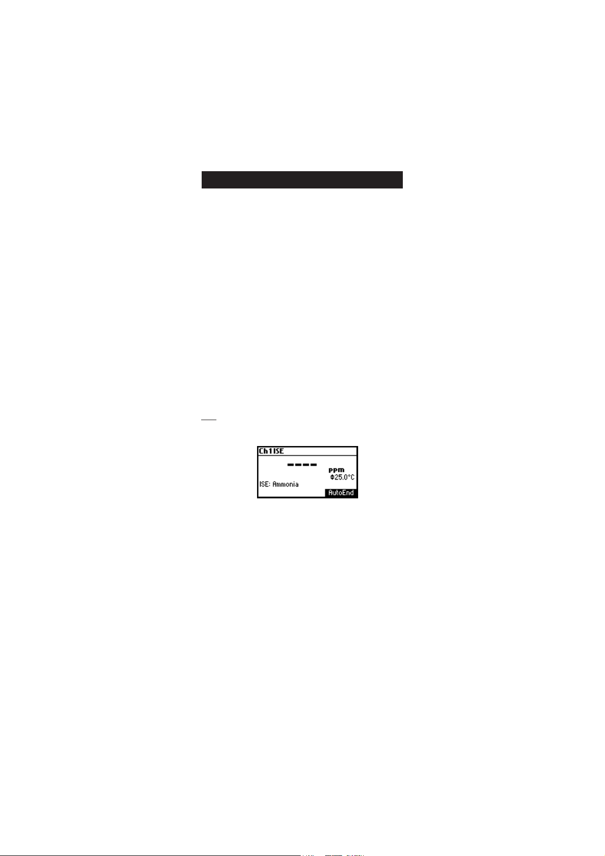
ISE MEASUREMENTS
To perform ion concentration measurements, connect an ISE electrode
(and the corresponding reference if necessary) to the corresponding
BNC input and turn it ON.
12
Page 13
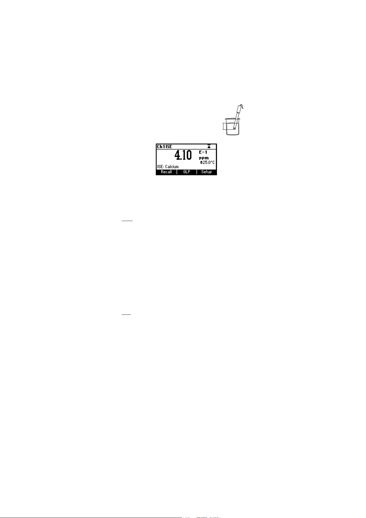
Submerse the ISE electrode tip 3 cm (1¼”) into the
sample to be tested and wait for the reading to
stabilize.
The ISE reading will be displayed along with the
3 cm
current temperature reading.
The ”ATC“(or “MTC”) message is turned off because ppm readings are
not temperature compensated.
In order to take accurate ISE measurements, make sure that the appropriate
ISE electrode type and ISE unit were set in SETUP menu and the
instrument was calibrated (see ISE CALIBRATION for details, page 29).
Notes: • When the reading is out of range, the display will flash the
closest full-scale value.
• The instrument will display “----” on the primary LCD if it is
not calibrated. Perform at least a single-point calibration in
order to take ISE measurements.
• Changing the selection in the SETUP menu for the ISE
electrode or the ISE parameter will require calibration.
TEMPERATURE MEASUREMENTS
pH channel
Connect the HI 7662-T temperature probe to the appropriate socket.
Immerse the temperature probe into the sample and allow the reading
on the secondary LCD to stabilize.
Note: The temperature can be displayed in Celsius degrees (ºC) or in
Fahrenheit degrees (ºF) (see SETUP for details, page 40).
EC/TDS/NaCl/Resistivity channel
Immerse the conductivity probe (which includes also the temperature
sensor) into the solution to be tested. The sleeve holes must be completely
submerged. Tap the probe repeatedly to remove any air bubbles that
may be trapped inside the sleeve.
If needed, press CHANNEL to select EC channel or/and press RANGE
repeatedly until the desired range (EC, Resistivity, TDS, Salt) is selected on
the LCD. If needed, select the “Automatic” or “No TC” compensation mode
to perform temperature measurements (see SETUP for details, page 40).
Allow for the reading to stabilize. The main LCD line displays the
measurement in the selected range, while the temperature is
displayed on the lower LCD line.
13
Page 14
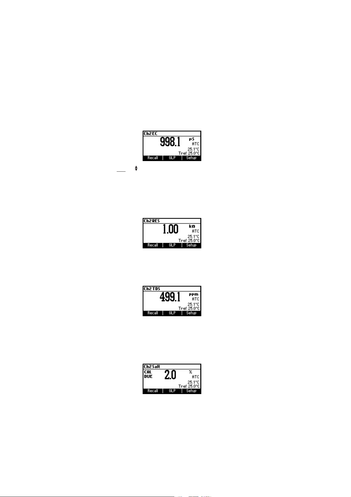
EC range
The conductivity range is from 0 to 400 mS/cm . The actual conductivity
range (the uncompensated conductivity) is up to 1000 mS/cm. The
instrument will display conductivity readings up to 1000 mS/cm.
Note: The symbol in front of the temperature reading means that the
temperature can be entered by the user (“Manual” option
selected in SETUP).
Resistivity range
The reciprocal of the conductivity of a material is the resistivity.
TDS range
A conductivity measured value can be corrected to a total disolved solids
value using the TDS factor (value entered in SETUP).
Salinity
The salinity is derived from the conductivity of a sample.
The percent of salinity in a sample is depending of the sample and on the
salinity coefficient.
14
Page 15
AUTO-RANGING EC CHANNELAUTO-RANGING EC CHANNEL
AUTO-RANGING EC CHANNEL
AUTO-RANGING EC CHANNELAUTO-RANGING EC CHANNEL
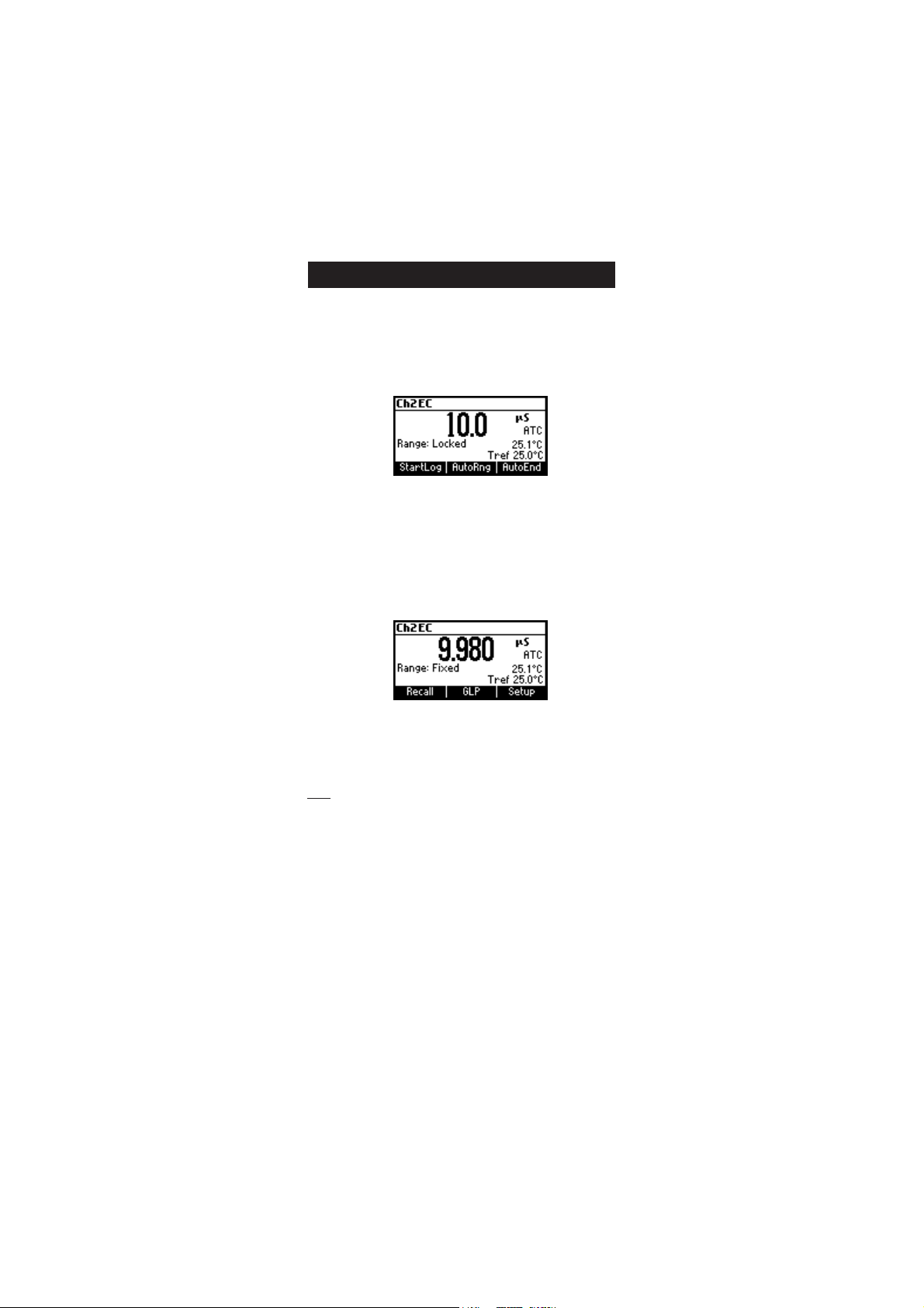
The EC, Resistivity and TDS scales are auto-ranging. The meter automatically
sets the scale with the highest possible resolution.
By pressing Lock, the auto-ranging feature is disabled and the current
range is frozen on the LCD.
The “Range: Locked” message is displayed. To restore the auto-ranging
option press AutoRng functional key again.
The auto-ranging mode is also disabled by selecting a “fixed range” in
the SETUP menu. While in fixed range mode the instrument will display
the readings with the fixed resolution. Maximum 6 digits can be
displayed.
The top of the fixed range is displayed blinking when the reading exceeds
this value.
To disable fixed range mode enter SETUP and select auto-ranging mode.
Note: Auto-ranging is automatically restored if the range is changed, if
the meter is turned off and back on again or if the calibration
mode is entered.
15
Page 16
TEMPERATURE COMPENSATION EC CHANNELTEMPERATURE COMPENSATION EC CHANNEL
TEMPERATURE COMPENSATION EC CHANNEL
TEMPERATURE COMPENSATION EC CHANNELTEMPERATURE COMPENSATION EC CHANNEL
The conductivity of a solution with a specific electrolyte concentration
changes with temperature. The relationship of the change in conductivity
as a function of temperature is described by a solution’s temperature
coefficient. This coefficient varies with each solution and is user selectable
(see SETUP mode).
Two selectable temperature sources are available: reading directly from
the sensor inside the probe or manual entry.
Three options of linear temperature compensation are available:
Automatic: temperature readings from the sensor inside the EC probe.
Manual: temperature entered manually by the user.
No Temperature Compensation (No TC): The temperature shown on
the LCD is not taken into account. The meter displays the actual
conductivity.
To select the desired option enter SETUP menu (see page 40).
If the temperature is out of the -20 °C - 120 °C range the instrument will
not do temperature compensation.
16
Page 17
Cº Fº
0307IH
0308IH
(µ )mc/S
1307IH
1308IH
(µ )mc/S
3307IH
3308IH
(µ )mc/S
4307IH
4308IH
(µ )mc/S
5307IH
5308IH
(µ )mc/S
9307IH
9308IH
(µ )mc/S
0
5
01
51
61
71
81
91
02
12
22
32
42
52
62
72
82
92
03
13
23
14
05
95
8.06
6.26
4.46
2.66
86
8.96
6.17
4.37
2.57
77
8.87
6.08
4.28
2.48
68
8.78
0517
0228
0339
08401
02701
05901
09111
03411
07611
01911
05121
09321
04621
08821
03131
07331
02631
07831
02141
07341
677
698
0201
7411
3711
9911
5221
1521
8721
5031
2331
9531
6831
3141
0441
7641
4941
1251
8451
5751
46
56
76
86
07
17
37
47
67
87
97
18
28
48
68
78
98
09
29
49
00384
00535
00695
00456
00276
00586
00896
00317
00427
00047
00257
00567
00387
00008
00318
00038
00948
00368
00288
00009
00456
00147
00238
00529
00449
00369
00289
002001
001201
000401
009501
009701
008901
008111
008311
007511
007711
007911
008121
009321
0672
0813
5163
3604
5514
5424
7334
9244
3254
7164
1174
5084
2094
0005
6905
0915
6825
3835
9745
5755
CONDUCTIVITY VERSUSCONDUCTIVITY VERSUS
CONDUCTIVITY VERSUS
CONDUCTIVITY VERSUSCONDUCTIVITY VERSUS
TEMPERATURE CHARTTEMPERATURE CHART
TEMPERATURE CHART
TEMPERATURE CHARTTEMPERATURE CHART
The conductivity of an aqueous solution is the measure of its ability to
carry an electrical current by means of ionic motion.
The conductivity invariably increases with increasing temperature.
It is affected by the type and number of ions in the solution and by the
viscosity of the solution itself. Both parameters are temperature dependent.
The dependency of conductivity on temperature is expressed as a relative
change per Celsius degree at a particular temperature, commonly as
percent per ºC.
The following table lists the temperature dependence of the HANNA
calibration buffers.
BACKLIGHT FEATURE
The instrument is provided with a Backlight feature. The Backlight levels
can be selected in the SETUP menu.
17
Page 18

USERUSER
CALIBRATION CALIBRATION
USER
CALIBRATION
USERUSER
CALIBRATION CALIBRATION
To enter User Calibration screen press CAL key while in pH/Rel mV/ISE
range (pH channel) or EC/Salinity range (EC channel).
From EC range
Press the corresponding functional key to enter:
• EC user calibration.
• Ch2 temperature user calibration.
From pH range
Press the corresponding functional key to enter:
• pH user calibration.
• Ch1 temperature user calibration.
Note: For REL mV, ISE or Salinity range, pressing CAL on the selected
range will cause the meter to enter directly in calibration mode.
18
Page 19

pp
H CALIBRATIONH CALIBRATION
p
H CALIBRATION
pp
H CALIBRATIONH CALIBRATION
It is recommended to calibrate the instrument frequently, especially if
high accuracy is required.
The pH range should be recalibrated:
• Whenever the pH electrode is replaced.
• At least once a week.
• After testing aggressive chemicals.
• When calibration alarm time out is expired - “CAL DUE” blinks (if
feature is enabled in SETUP).
• If “Out of cal. range” message appears on the LCD during pH
measurement (the measurement range is not covered by current
calibration, if this feature is enabled in SETUP).
PROCEDURE
The HI 3512 offers a choice of 7 standard buffers (1.68, 4.01, 6.86,
7.01, 9.18, 10.01 and 12.45 pH) and up to 2 custom buffers. The
standard pH buffers are temperature compensated during calibration.
The custom, user entered buffers are not temperature compensated
during calibration.
When a custom buffer is selected during calibration, the Custom function
key is displayed on the LCD. Press Custom key in order to alter the value
to the actual pH value at the temperature of measurement. Use
ARROW keys to change the value within a ±1.00 pH window and
then press Accept. Press ESC to leave custom buffers value unchanged.
Press Confirm.
For accurate pH measurements, it is recommended to perform a multipoint
calibration. At least a two-point calibration is required.
The instrument will automatically skip the buffers within ±0.2 pH
window, around one of the calibrated buffers.
• Pour small quantities of selected buffer solutions into clean beakers.
For accurate calibration use two beakers for each buffer solution, the
first one for rinsing the electrode and the second one for calibration.
• Remove the protective cap, open the fill hole and rinse the electrode
with some of the buffer solution to be used for the first calibration
point.
19
Page 20

FIVE-POINT CALIBRATIONFIVE-POINT CALIBRATION
FIVE-POINT CALIBRATION
FIVE-POINT CALIBRATIONFIVE-POINT CALIBRATION
• Immerse the pH electrode and the temperature
probe approximately 3 cm (1¼”) into a buffer
solution of your
7.01, 9.18, 10.01, 12.45 or a custom buffer)
choice (pH 1.68, 4.01, 6.86,
3 cm
and stir the buffer gently. The temperature probe
should be close to the pH electrode.
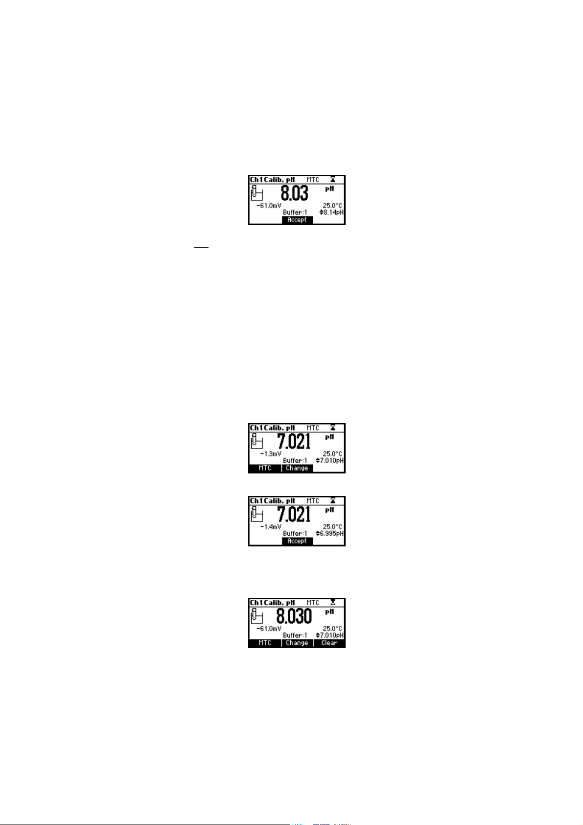
• Enter pH calibration. The instrument will display the measured pH,
the LCD first expected buffer and the temperature reading.
• If necessary, press the ARROW keys to select a different buffer value.
• The “ ” tag will blink on the LCD until the reading is stable.
• When the reading is stable and close to the selected buffer, Confirm
function key is displayed.
• Press Confirm to confirm first point.
• The calibrated value and the second expected buffer value is then
displayed on the LCD.
• After the first calibration point is confirmed, immerse the pH electrode
and the temperature probe approximately 3 cm (1¾”) into the
second buffer solution and stir gently. The temperature probe should
be close to the pH electrode.
• If necessary, press the ARROW keys to select a different buffer value.
• The “ ” tag will blink on the LCD until the reading is stable.
20
Page 21
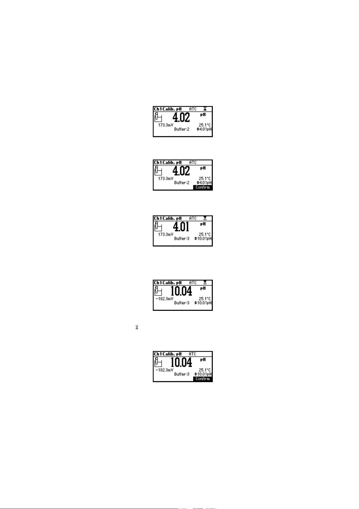
• When the reading is stable and close to the selected buffer, the
Confirm function key is displayed.
• Press Confirm to confirm calibration.
• The calibrated value and the third expected buffer value will be
displayed.
• After the second calibration point is confirmed, immerse the pH
electrode and the temperature probe approximately 3 cm (1¾”) into
a third buffer solution and stir gently. The temperature probe should
be close to the pH electrode.
• If necessary, press the ARROW keys to select a different buffer value.
• The “ ” tag will blink on the LCD until the reading is stable.
• When the reading is stable and close to the selected buffer, the
Confirm function key is displayed.
• Press Confirm to confirm calibration.
Repeat this procedure with two additional pH buffers to encompass the
entire sample pH range.
21
Page 22
FOUR, THREE or TWO-POINT CALIBRATION
• Proceed as described in “FIVE-POINT CALIBRATION” section.
• Press ESC after the appropriate accepted calibration point. The
instruments will return to calibration screen and will memorize the
calibration data.
SINGLE-POINT CALIBRATION
There are two selectable options for a single-point calibration:
Replace and Offset.
This option is configured in SETUP mode under the parameter First Point
Mode. In both cases the meter will alter the present calibration data in
the instrument. If “Replace” is selected a new calibration point will be
added to the existing data, and the slope is calculated. The slopes
between current buffer and nearest lower and higher buffers will be
reevaluated.
If the “Offset” option is selected, an electrode offset correction is
performed to all buffer data keeping the existing slopes unchanged.
• Proceed as described in “FIVE-POINT CALIBRATION” section.
• Press ESC after the first calibration point was confirmed. The instruments
will memorize the single-point calibration data and will return to
calibration screen.
Notes: • Press MTC key to toggle between pH buffer selection and the
temperature reading during calibration while temperature
probe is disconnected (MTC mode).
• The displayed arrow is moving to the temperature value.
Use ARROW keys in order to change the temperature.
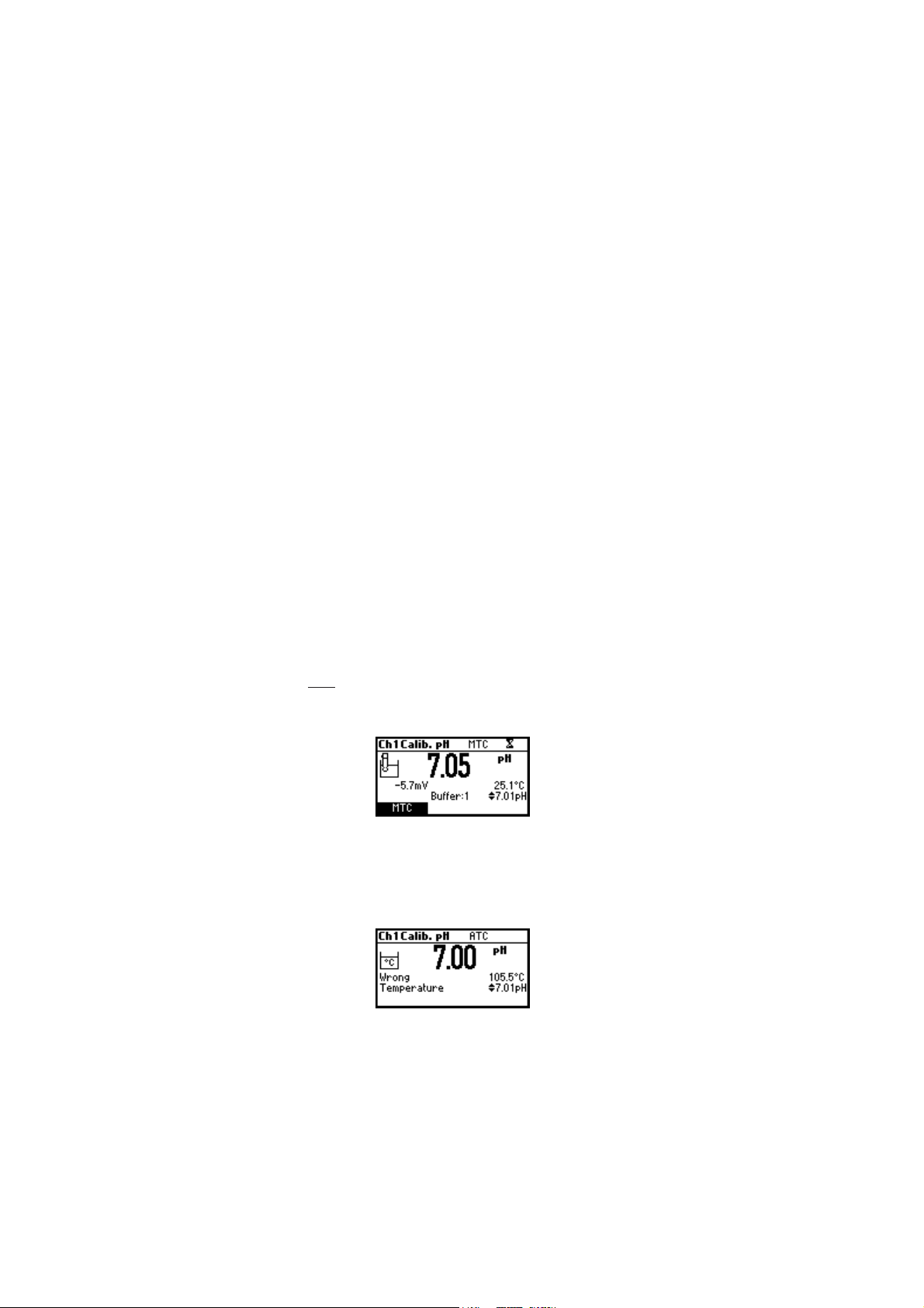
ERROR SCREENS
Wrong temperature
The calibration cannot be confirmed.
If the temperature is less than 0 °C or greater than 100 °C during
calibration, the calibration cannot be confirmed.
22
Page 23
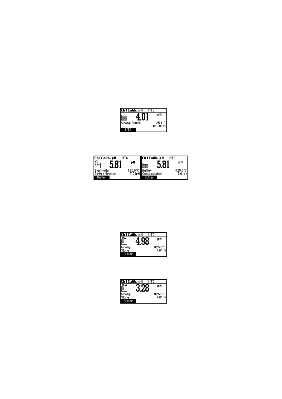
Wrong buffer
The calibration cannot be confirmed.
The pH reading is not close to the selected buffer. Select another buffer
using the ARROW keys or change the buffer.
“Electrode Dirty/Broken“ alternatively with “Buffer Contaminated“.
The calibration cannot be confirmed.
The offset of the electrode is not in the accepted range. Check if the
electrode is broken or clean it following the CLEANING PROCEDURE (see
page 74). Check the quality of the buffer. If necessary, change the
buffer.
Wrong slope
The calibration cannot be confirmed.
The evaluated slope is less than the lowest accepted value (80% of
default slope).
The evaluated slope is more than the highest accepted value (110 % of
default slope).
23
Page 24

Wrong old slope
An inconsistency between new and previous (old) calibration is detected.
Clear old calibration parameters and initiate calibration from the current
point. The instrument will keep all confirmed values during current
calibration.
Note: For single-point calibration the electrode condition is not displayed
in the measurement screen.
Each time a buffer is confirmed, the new calibration parameters replace
the older calibration parameters of the corresponding buffer.
If an additional single buffer calibration is added at a latter time, the
new buffer point will be added to the stored calibration.
If the existing stored calibration is full (five calibration points), after
confirming the calibration point, the instrument will ask which buffer will
be replaced by current buffer. On the Buffer line will be displayed the
proposed buffer.
Press ARROW keys to select another buffer to be replaced.
Press Confirm to confirm the buffer that will be replaced.
Press ESC to exit mode. In this case, the buffer will not be entered.
Note: The replaced buffer is not removed from calibration list and it can
be selected for the next calibration points.
WORKING WITH CUSTOM BUFFERS
If at least one custom buffer was set in SETUP menu, it can be selected
for calibration by pressing the ARROW keys. The Custom function key
will be displayed.
Press Custom if you want to adjust the buffer to its value at the current
temperature.
24
Page 25
Use the ARROW keys to change the buffer value.
Press Accept to accept new value or ESC to exit mode.
Note: Custom buffer value can be adjusted within a ±1.00 pH window,
around the set value.
WORKING WITH MILI pH BUFFERS
HANNA millesimal pH buffers are ± 0.002 pH buffers formulated to
correspond to nominal pH values. (1.000, 2.000, 3.000, 4.010, 5.000,
6.000, 7.010, 8.000, 9.000, 10.010, 11.000, 12.000, 13.000 and 9
that fall between). These buffers require the user to use the closest
standard buffer and adjust it, or to use custom buffers. With these buffers
it is possible to closely bracket the measurement range of interest and
insure an accurate measurement.
The resolution of the meter must be set to 0.001 pH (see SETUP on page 40).
Eight buffers are stored in instrument for calibration.
If calibration is invoked using millesimal buffers, the calibration buffer
can be modified within a ±0.020 pH range in accordance with the
label on the calibration buffer.
Press Change to enter buffer adjust mode.
Use ARROW keys to change the buffer value.
Press Accept to accept new value or ESC to exit adjusting mode.
CLEAR CALIBRATION
Press Clear function key when displayed to clear previous calibrations.
25
Page 26
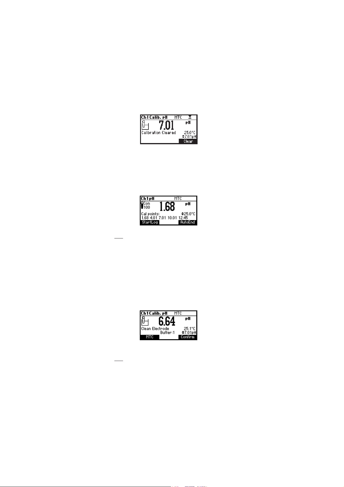
The instrument will display “Calibration Cleared” and the instrument
returns to measuring mode.
ELECTRODE CONDITION
The display is provided with an icon, and a numeric value (unless the
feature is disabled) which gives an indication of the electrode status after
calibration.
The indication remains active until the end of the calibration day.
Note: The electrode condition is evaluated only if current calibration
includes at least two standard buffers.
CLEAN ELECTRODE WARNING
Each time pH calibration is performed, the instrument internally
compares the new calibration with the one previously stored.
When this comparison indicates a significant difference, the “Clean
Electrode” warning message is displayed to advise the user that the pH
electrode may need to be cleaned (see ELECTRODE CONDITIONING &
MAINTENANCE section for details, page 72).
After cleaning, perform a new calibration.
Note: If the calibration data are cleared, the comparison is done with
the default values.
26
Page 27
PMET SREFFUBHp
Cº Fº 86.1 10.4 68.6 10.7 81.9 10.01 54.21
0 23 76.1 10.4 89.6 31.7 64.9 23.01 83.31
5 14 76.1 00.4 59.6 01.7 93.9 42.01 81.31
01 05 76.1 00.4 29.6 70.7 33.9 81.01 99.21
51 95 76.1 00.4 09.6 50.7 72.9 21.01 08.21
02 86 86.1 00.4 88.6 30.7 22.9 60.01 26.21
52 77 86.1 10.4 68.6 10.7 81.9 10.01 54.21
03 68 86.1 20.4 58.6 00.7 41.9 69.9 92.21
53 59 96.1 30.4 48.6 99.6 11.9 29.9 31.21
04 401 96.1 40.4 48.6 89.6 70.9 88.9 89.11
54 311 07.1 50.4 38.6 89.6 40.9 58.9 38.11
05 221 17.1 60.4 38.6 89.6 10.9 28.9 07.11
55 131 27.1 80.4 48.6 89.6 99.8 97.9 75.11
06 041 27.1 90.4 48.6 89.6 79.8 77.9 44.11
56 941 37.1 11.4 48.6 99.6 59.8 67.9 23.11
07 851 47.1 21.4 58.6 99.6 39.8 57.9 12.11
57 761 67.1 41.4 68.6 00.7 19.8 47.9 01.11
08 671 77.1 61.4 78.6 10.7 98.8 47.9 00.11
58 581 87.1 71.4 78.6 20.7 78.8 47.9 19.01
09 491 97.1 91.4 88.6 30.7 58.8 57.9 28.01
59 302 18.1 02.4 98.6 40.7 38.8 67.9 37.01
pp
H BUFFER TEMPERATUREH BUFFER TEMPERATURE
p
H BUFFER TEMPERATURE
pp
H BUFFER TEMPERATUREH BUFFER TEMPERATURE
DEPENDENCEDEPENDENCE
DEPENDENCE
DEPENDENCEDEPENDENCE
Temperature has an effect on pH buffers. During calibration the
instrument will automatically calibrate to the pH value corresponding
to the measured or set temperature.
During calibration the instrument will display the pH buffer value at 25 ºC.
27
Page 28

RELATIVE RELATIVE
RELATIVE
RELATIVE RELATIVE
The relative mV value calibration may be used to perform a single point
calibration with an ORP standard or remove the contribution of the
reference electrode to display mV equivalent to a SHE.
• Press CAL when the instrument is in Relative mV measurement
mode. The relative mV value and the temperature values are
displayed.
• Use the ARROW keys if you want to change the displayed relative
mV value.
• Press Zero function key if you want Rel mV reading to be zero
(Relative mV offset equals the mV reading).
• When the reading is stable in mV range and the Relative mV offset
is inside the offset window (±2000 mV), the Confirm function key
is displayed.
mm
V CALIBRATIONV CALIBRATION
m
V CALIBRATION
mm
V CALIBRATIONV CALIBRATION
• Press Confirm to confirm relative mV calibration. The instrument will
return to measurement mode.
• If the absolute mV reading is out of range or the Relative mV offset
is out of the offset window, “Wrong relative offset” message is
displayed.
Change the input value or the Relative mV value to complete the
calibration process.
Note: If a Rel mV offset calibration exists, CLR function key is
displayed. Press CLR if you want Rel mV offset to be 0.0 mV.
28
Page 29
II
SESE
CALIBRATION CALIBRATION
I
SE
CALIBRATION
II
SESE
CALIBRATION CALIBRATION
It is recommended to calibrate the instrument frequently, especially if
high accuracy is required.
The ISE range should be recalibrated:
• Whenever the ISE probe or ion charge is changed.
• At least once a day.
• After testing aggressive chemicals.
• When calibration alarm time out is expired- “CAL DUE” warning
blinks (if feature is enabled).
Follow instructions for the individual electrode.
Due to electrode conditioning time, the electrode must be kept immersed
a few seconds to stabilize. The user will be guided step by step during
calibration with easy to follow messages on the LCD. This will make the
calibration a simple and error-free procedure.
PROCEDURE
Select the proper ISE probe in SETUP menu or select the proper Ion
Charge slope (see SETUP for details, page 40).
Note: If the ISE probe has not been previously calibrated (at least one
point), the “----” will be displayed.
Pour small quantities of the buffer solutions into clean beakers. If possible,
use plastic beakers to minimize any EMC interferences.
For accurate calibration and to minimize cross-contamination, use two
beakers for each standard solution. One for rinsing the electrode and one
for calibration.
The HI 3512 permits a 5 point calibration in 6 standard solutions
(0.1, 1, 10, 100, 1000, 10000). It is advised to bracket expected ion
concentration with your standards. For fluoride electrode the 2 ppm
standard is also available.
For accurate ISE measurements it is recommended to perform a multipoint
calibration. At least a two-point calibration is required.
Remove the protective cap from the ISE electrode.
29
Page 30
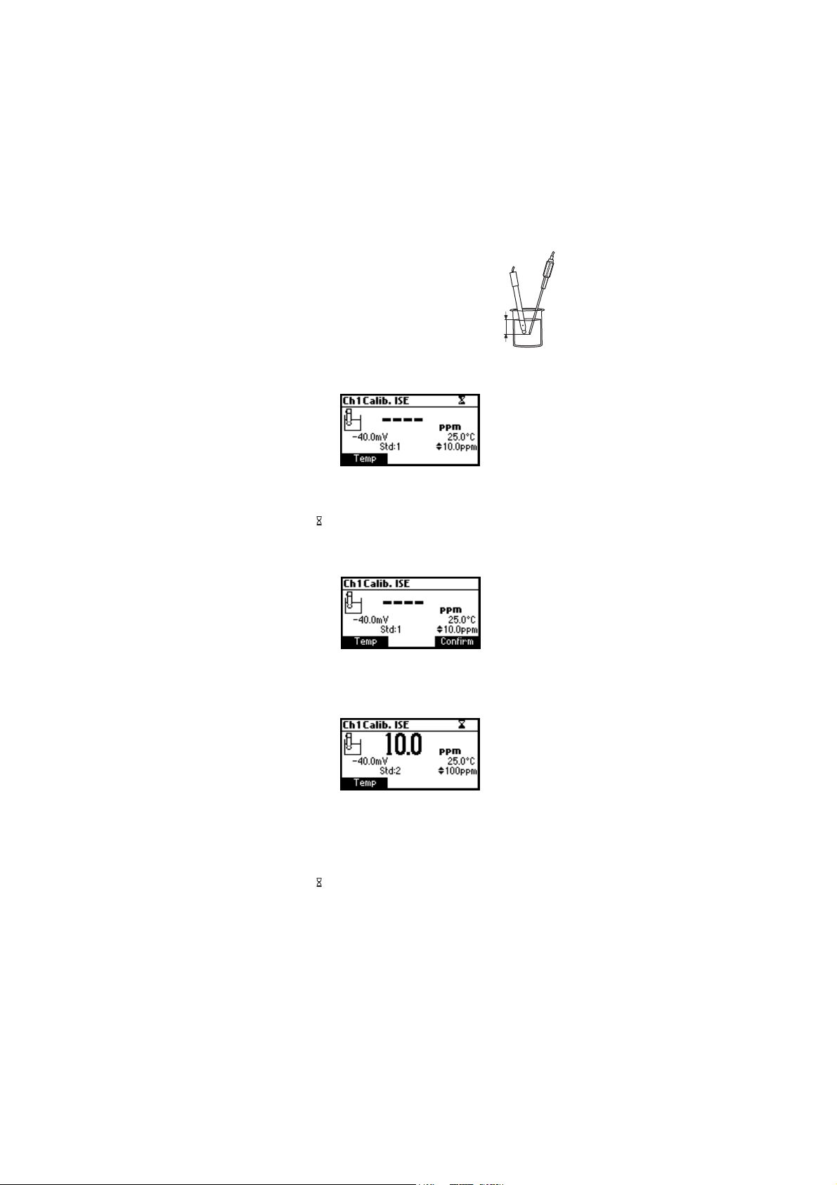
FIVE-POINT CALIBRATION
Use part of this procedure for 2, 3 or 4 point
calibration. Press ESC.
• Immerse the ISE electrode approximately 2 cm
(¾”) into the less concentrated standard
2 cm
solution and stir gently.
• Press CAL. The primary LCD will displays the ion concentration in the
selected unit or “----” if not calibrated and first standard value.
• If necessary, press the ARROW keys to select a different standard
value.
• The “ ” tag will blink on the LCD until the reading is stable.
• When the reading is stable and close to the selected standard, the
Confirm function key is displayed.
• Press Confirm to confirm calibration.
• The calibrated value and the second expected standard value will be
displayed.
• After the first calibration point is confirmed, immerse the ISE electrode
approximately 2 cm (¾”) into the second calibration solution.
• If necessary, press the ARROW keys to select a different standard
value.
• The “ ” tag will blink on the LCD until the reading is stable.
• When the reading is stable and close to the selected standard, the
Confirm function key is displayed.
• Press Confirm to confirm calibration.
30
Page 31

• The calibrated value and the third expected standard value will be
displayed.
• After the second calibration point is confirmed, immerse the ISE
electrode approximately 2 cm (¾”) into the third calibration solution.
• If necessary, press the ARROW keys to select a different standard
value.
• The “ ” tag will blink on the LCD until the reading is stable.
• When the reading is stable and close to the selected standard, the
Confirm function key is displayed.
• Press Confirm to confirm calibration.
• The calibrated value and the fourth expected standard value will be
displayed.
• After the third calibration point is confirmed, immerse the ISE electrode
approximately 2 cm (¾”) into the fourth calibration solution.
• If necessary, press the ARROW keys to select a different standard
value.
• The “ ” tag will blink on the LCD until the reading is stable.
• When the reading is stable and close to the selected standard, the
Confirm function key is displayed.
• Press Confirm to confirm calibration.
• The calibrated value and the fifth expected standard value will be
displayed.
• After the fourth calibration point is confirmed, immerse the ISE
electrode approximately 2 cm (¾”) into the fifth calibration solution.
• If necessary, press the ARROW keys to select a different standard
value.
• The “ ” tag will blink on the LCD until the reading is stable.
• When the reading is stable and close to the selected standard, the
Confirm function key is displayed.
• Press Confirm to confirm calibration. The instrument stores the
calibration value and returns to normal measurement mode.
Note: The instrument will automatically skip the standard solutions
used during calibration.
31
Page 32

ERROR SCREENS
Wrong standard
The calibration cannot be confirmed. Verify that the correct standard is
selected.
The message appears if mV input is out of ±2000 mV range.
Wrong slope
The calibration cannot be confirmed.
This message is displayed if slope is out of the accepted range.
Slope under accepted value (30 % default slope). Verify that the correct
standard is selected.
Slope over accepted value (130 % default slope).
Wrong old slope
An inconsistency between present and previous (old) calibration is
detected. Clear old calibration parameters and continue calibration from
the current point. The instrument will keep all confirmed values during
current calibration.
The instrument will display “----“on the primary LCD if is not calibrated
or after all calibrations are cleared.
If “Clear“ is pressed during the first calibration point, the instrument
returns to measurement mode.
Notes: • Press Temp function key to select temperature value to be
changed if the temperature probe is not connected;
• ISE range is not temperature compensated on this meter;
• Standards and samples should be at the same temperature.
32
Page 33

ECEC
CALIBRATION CALIBRATION
EC
CALIBRATION
ECEC
CALIBRATION CALIBRATION
It is recommended to calibrate the instrument frequently, especially if
high accuracy is required.
The EC range should be recalibrated:
• Whenever the EC electrode is replaced.
• At least once a week.
• After testing aggressive chemicals.
• When calibration alarm time out is expired - “CAL DUE” blinks (if
feature is enabled in SETUP).
• If “Out of cal. range” message appears on the LCD during EC
measurement (the measurement range is not covered by current
calibration, if feature is enabled in SETUP).
Note: TDS and Resistivity readings are automatically derived from the
EC reading and no specific calibration is needed.
PROCEDURE
HI 3512 instrument offers a choice of 7 memorized standards
(0.00 µS/cm, 84.0 µS/cm, 1.413 mS/cm, 5.00 mS/cm,
12.88 mS/cm, 80.0 mS/cm and 111.8 mS/cm).
For accurate EC measurements, it is recommended to perform an offset
calibration and slope calibration in the nearest value standard solution
of the samples readings (two-point calibration).
The instrument will automatically recognize the standards and skip the
standard used during calibration.
• Pour small quantities of selected standard solutions into clean
beakers. For accurate calibration use two beakers for each standard
solution, the first one for rinsing the electrode and the second one for
calibration.
• Remove the protective cap and rinse the electrode with some of the
standard solution to be used for the first calibration point.
TWO-POINT CALIBRATION
• It is better to perform the first point calibration as offset calibration.
• Tap the probe repeatedly to remove any air bubbles that may be
trapped inside the sleeve.
• For offset (zero) calibration, just leave the dry probe in the air.
33
Page 34

• Press CAL from EC range to enter calibration mode.
• Leave the probe in the air and press EC. The instrument will display
the measured EC on the LCD, first expected standard and the
temperature reading.
• If necessary, press the ARROW keys to select a different standard
value.
• The “ ” tag will blink on the LCD until the reading is stable.
• When the reading is stable and close to the selected buffer, Confirm
functional key is displayed.
• Press Confirm to confirm first point.
• The calibrated value and the second expected standard value is then
displayed on the LCD.
• After the first calibration point is confirmed, immerse the EC electrode
into the second standard solution and stir gently. Tap the probe
repeatedly to remove any air bubbles that may be trapped inside
the sleeve. The instrument will automatically detect the standard
after few seconds the reading is stable.
• If necessary, press the ARROW keys to select a different standard
value.
• The “ ” tag will blink on the LCD until the reading is stable.
34
Page 35

• When the reading is stable and close to the selected standard, the
Confirm functional key is displayed.
• Press Confirm to confirm calibration.
ERROR SCREENS
Wrong standard
The calibration cannot be confirmed.
The EC reading is not close to the selected standard or the temperature
is out of the 0 - 60 °C window. Select another standard using the
ARROW keys or change the temperature value.
CLEAR CALIBRATION
Press Clear functional key when displayed to clear old calibrations.
All old calibrations, are cleared and the instrument returns to measurement
mode.
NaCl CALIBRATION
NaCl calibration is a one-point procedure in 100.0% NaCl solution. Use
the HI 7037L calibration solution (sea water solution) as a 100% NaCl
standard solution.
• To enter NaCl calibration select the Salinity % range and press CAL.
• The measured % NaCl, the temperature and the 100% NaCl
standard are displayed.
35
Page 36
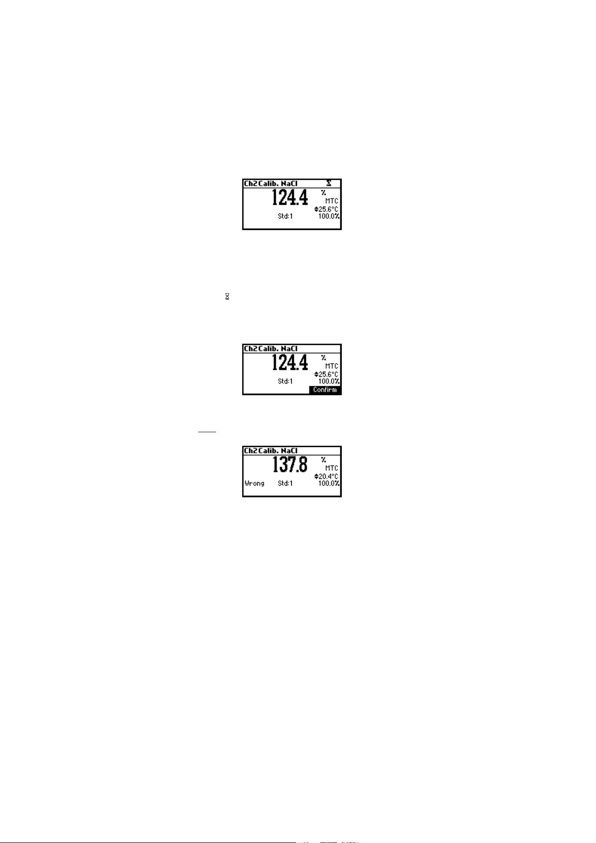
• Rinse the probe with some of the calibration solution or deionized
water. Immerse the probe into HI 7037L solution. Tap the probe
repeatedly to remove any air bubbles that may be trapped inside
the sleeve.
• The “ ” tag will blink on the LCD until the reading is stable.
• When the reading is stable, the Confirm functional key is displayed.
Press Confirm to confirm calibration.
• The instrument returns to measurement mode.
Notes:
• If the uncalibrated reading is too far from the expected value,
calibration is not recognized. The “Wrong” message will be
displayed.
• The meter uses 1.90 %/°C temperature compensation factor during
calibration. If the “Temperature Coef” in the Setup menu has
been set to a different value, when exiting calibration mode, the
displayed value might be different from the nominal standard value.
36
Page 37

GOOD LABORATORY PRACTICE (GLP)GOOD LABORATORY PRACTICE (GLP)
GOOD LABORATORY PRACTICE (GLP)
GOOD LABORATORY PRACTICE (GLP)GOOD LABORATORY PRACTICE (GLP)
GLP is a set of functions that allows storage and retrieval of data
regarding the maintenance and status of the electrode.
All data regarding pH, Rel mV, ISE, EC or Salinity calibration is stored for
the user to review when necessary.
EXPIRED CALIBRATION
The instrument is provided with a real time clock (RTC), in order to
monitor the time elapsed since the last pH calibration.
The real time clock is reset every time the instrument is calibrated and the
“expired calibration” status is triggered when the instrument detects a
calibration time out. The “CAL DUE” warning will start blinking to warn
the user that the instrument should be recalibrated.
The calibration time out can be set (see SETUP for details, page 40) from
1 to 7 days or can be disabled.
For example, if a 4 days time out has been selected, the instrument will
issue the alarm exactly 4 days after the last calibration.
However, if at any moment the expiration value is changed (e.g. to 5
days), then the alarm will be immediately recalculated and appear 5
days after the last calibration.
Notes: • When the instrument is not calibrated or calibration is cleared
(default values loaded) there is no “expired calibration”,
and the display always shows the “CAL DUE” warning
blinking.
• When an abnormal condition in the RTC (Real Time Clock) is
detected, the instrument forces the “expired calibration”
status.
LAST pH CALIBRATION DATA
The last pH calibration data is stored automatically after a successful
calibration.
To view the pH calibration data, press GLP function key when the
instrument is in the pH measurement mode. If GLP function key is not
displayed press MENU key.
The instrument will display a lot of data including calibration buffer,
offset, slope, electrode condition.
37
Page 38
Notes: • Buffers (standards) displayed in video inverse mode are
from previous calibrations (pH and ISE range only).
• The pH custom buffers are marked with an “*” on the
right side of the buffer value.
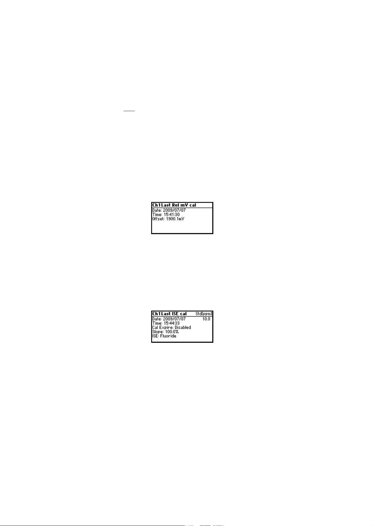
LAST RELATIVE mV CALIBRATION DATA
Last Relative mV calibration data is stored automatically after a successful
calibration.
To view the Relative mV calibration data, press GLP key while in Relative
mV measurement mode.
The instrument will display the Relative mV GLP information: calibration
date, time and offset.
LAST ISE CALIBRATION DATA
Last ISE calibration data is stored automatically after a successful
calibration.
To view the ISE calibration data, press GLP function key while in ISE
measurement mode. If GLP function key is not displayed press MENU
key.
The instrument will display the ISE calibration information: calibration
date, time, slope, calibration status and electrode type.
38
Page 39

LAST EC CALIBRATION DATA
The last pH calibration data is stored automatically after a successful
calibration.
To view the EC calibration data, press GLP when the instrument is in the
EC measurement mode.
The instrument will display a lot of data including calibration standards,
offset, time and date, cell constant, etc.
LAST NaCl % CALIBRATION DATA
Last NaCl calibration data is stored automatically after a successful
calibration.
To view the NaCl calibration data, press GLP key while in NaCl measurement
mode.
The instrument will display the NaCl information: calibration date, time
and salinity factor.
Notes: • Press ESC at any moment and the instrument will return to
measurement mode.
• If calibration has not been performed, the instrument
displays “No user calibration” message.
39
Page 40

SETUPSETUP
SETUP
SETUPSETUP
Setup mode allows viewing and modifying the measurement parameters.
These are general SETUP parameters for all the ranges and range specific
parameters.
The following table lists the general SETUP parameters, their valid range
and the factory default settings.
New Description Valid value Default
Backlight Backlight level 0 to 8 4
Contrast Contrast level 0 to 20 10
Date/Time 01.08.2009 to 12.31.2099 current
00:00 to 23:59 date/time
Time Format AM/PM or 24 hours 24 hours
Date Format DD/MM/YYYY YYYY/MM/DD
MM/DD/YYYY
YYYY/MM/DD
YYYY-MM-DD
Mon DD, YYYY
DD-Mon-YYYY
YYYY-Mon-DD
Language Message display Up to four English
language languages
Temperature ºC or ºF ºC
unit
AutoEnd Select AutoEnd Fast, Medium, Accurate Medium
Stability Stability Criteria
Log interval Select log interval Manual, AutoEnd, 5, 10, 30 s Manual
1, 2, 5, 10, 15, 30, 60, (Log on demand)
120, 180 min.
Beep ON Beeper Status Enabled or Disabled Disabled
Instrument ID Instrument identification 0000 to 9999 0000
Baud Rate Serial Communication 600, 1200, 2400, 4800 9600
9600, 19200, 38400
Meter Displays general
information information
40
Page 41

The following table lists the specific pH/ORP/ISE range parameters.
Item Description Valid value Default
Calibribration Number of days after Disable, 1 to 7 days Disable
Timeout Calibration warning
(pH/ISE) is displayed
First point Management of 1 Replace or offset Replace
mode (pH) point calibration
Custom buffer Custom buffer Max. 2 buffers No
(pH) setting
pH Resolution Set pH resolution 0.1, 0.01 0.01
display 0.001
View calibr. Display calibration Enable or disabled Enable
points (pH) points
Display out of calibr. Enable or disable Enable
range warning
ISE probe Type of ISE probe Custom or Standard (17) Fluoride
ISE unit ppt, g/L, ppm, mg/L, ppb, µg/L ppm
mg/mL, M, mol/L, mmol/L, % W/V, user
Ion Charge ±1, ±2, none +1
The following table lists the specific EC/TDS/NaCl/Resistivity range parameters:
Item Description Valid value Default
Calibribration Number of days after Disable, 1 to 7 days Disable
Timeout Calibration warning
(EC/Salinity) is displayed
Out cal Display warning if the Enable/Disable Disable
range check reading is too far from the
(EC range only) calibration points
Temperature No TC, MTC, ATC ATC
compensation
mode
Range select Fix one Automatic, Fix one Automatic
specific range resolution of
EC, resistivity or TDS range
Cell constant Manual set of 0.010 to 10.000 1.000
the cell constant
Temperature Set the coeficient 0.00 to 10.00 %/°C 1.90 %/°C
coeficient for linear temperature
compensation
Temperature Reference temperature 15 °C, 20 °C, 25 °C 25 °C
Ref
Temperature unit °C or °F °C
TDS factor 0.40 to 1.00 0.50
41
Page 42
To enter SETUP menu, press SETUP function key while in measuring
mode.
If SETUP is not displayed press MENU key.
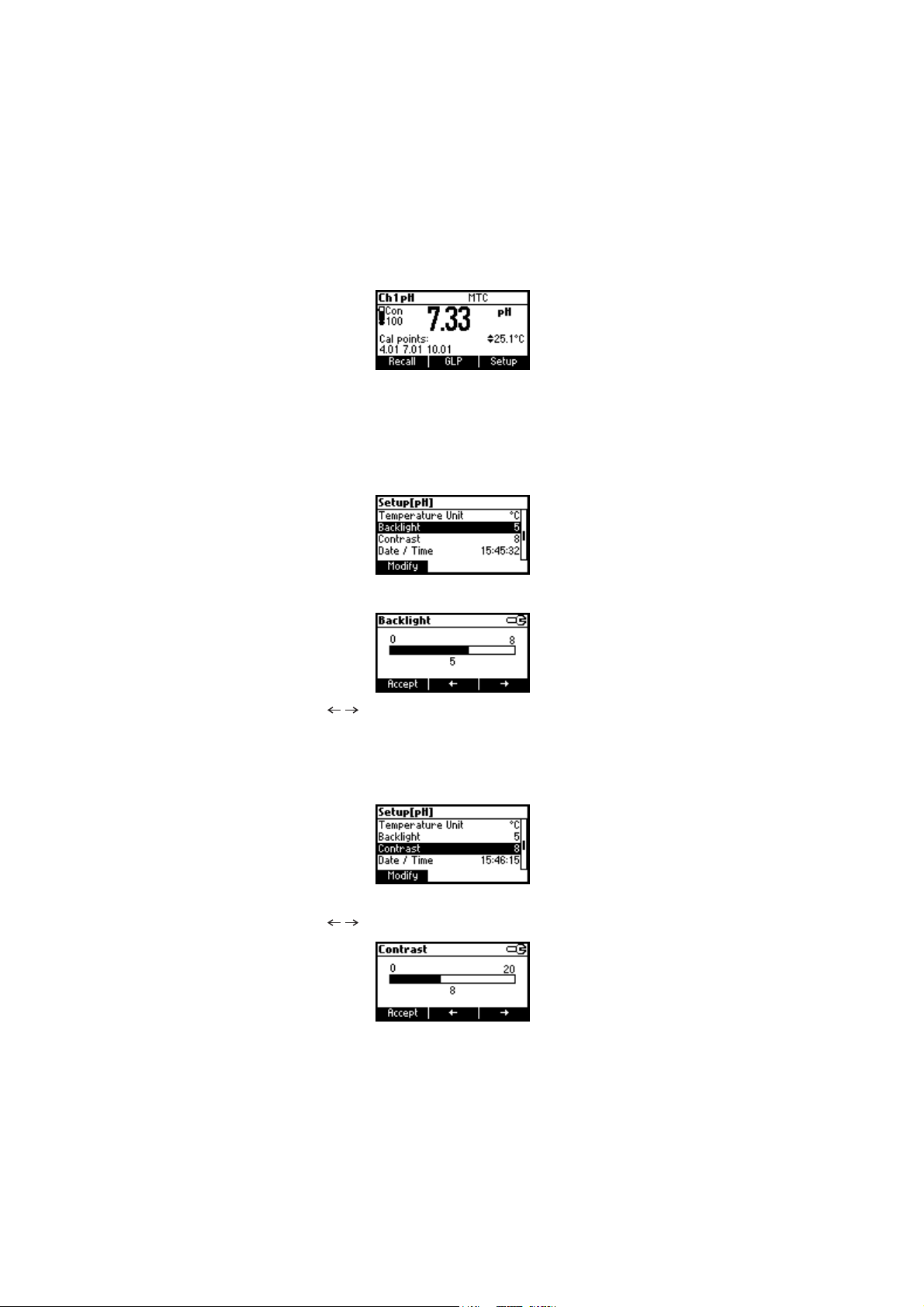
GENERAL PARAMETER SCREENS
Backlight
Focus on the
Press Modify.
Use / keys to change the intensity then press Accept to confirm.
Press ESC to leave without changing.
Backlight
item.
Contrast
Focus on the
Press Modify.
Use / keys to change contrast then press Accept to confirm.
Press ESC to leave without changing.
Contrast
item.
42
Page 43

Date/Time
Focus on the
Press Modify.
Use / keys to select item.
Use ARROW keys to change focused values.
Press Accept to confirm new setting, or ESC to leave without changing.
Time Format
Focus on the
Date/Time
Time Format
item.
item.
Press function key to change the option.
Date Format
Focus on the
Press Modify.
Use ARROW keys to select date format then press Accept.
Press ESC to leave without changing.
Date Format
item.
43
Page 44

Language
Focus on the
Use the desired function key to change the option. Wait until new
language is loaded. If language load fails the instrument will try to
reload current language.
If any language can’t be loaded, the instrument will work in safe mode.
In this mode all messages are displayed in English and HELP is not
available.
Temperature unit
Focus on the
Press the displayed function key in order to change the temperature unit.
Beep On
Focus on
Language
Temperature Unit
Beep On
item.
item.
item.
Press the displayed function key to enable/disable beep.
When enabled, beep sounds as a short beep every time a key is pressed
or when the calibration can be confirmed.
A long beep alert means that the pressed key is not active or a wrong
condition is detected while in calibration.
44
Page 45

AutoEnd stability
Focus on
AutoEnd Stability
Press one of the displayed function keys to select the AutoEnd stability
criteria.
Three options are available: Fast, Medium, Accurate.
For the pH range the stability criteria are different for different pH
resolution selected (Medium in 0.01 pH range is different than Medium
in 0.001 range).
Log interval
Focus on
Log interval
Press Modify in order to change the option.
item.
item.
Use the arrow keys in order to select an option.
If the selected option is Manual the Log on demand is selected.
If AutoEnd is selected the reading will be memorized only when is stable.
If a specific interval is selected, the reading is memorized at the start of
the specific interval.
45
Page 46
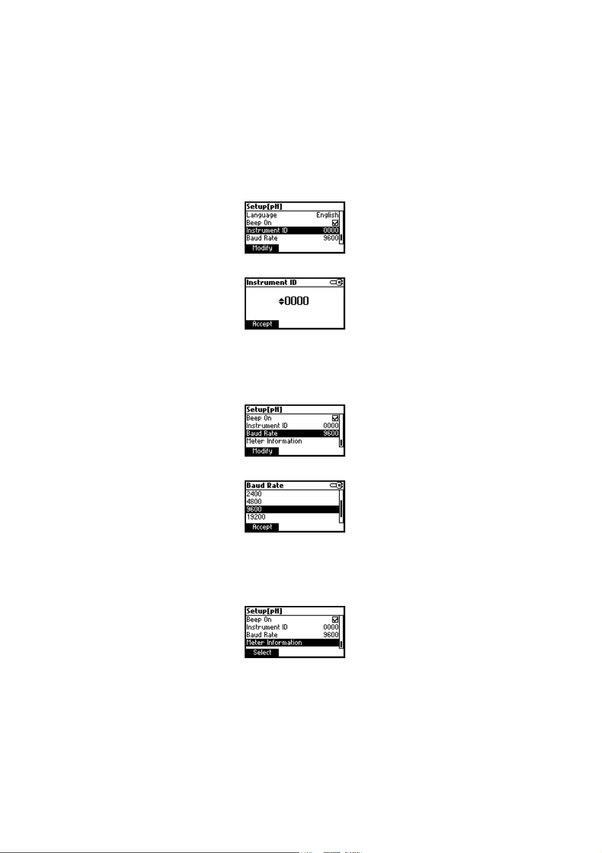
Instrument ID
Focus on the
Press Modify.
Use ARROW keys to change the instrument ID.
Press Accept to confirm or ESC to exit without saving.
Baud Rate
Focus on the
Press Modify.
Instrument ID
Baud Rate
item.
item.
Use ARROW keys to select the desired communication baud.
Press Accept to confirm or ESC to exit.
Meter information
Focus on the
Press Select.
Meter Information
item.
46
Page 47
The meter informations are displayed:
-firmware version
-language version
-mV/EC and temperature factory calibration time/date
pH CHANNEL RANGE SPECIFIC PARAMETERS SCREENS
Calibration Timeout
Focus on the
Press Modify.
Calibration Timeout
item.
Use ARROW keys to set desired value.
Press Accept to confirm or ESC to return without saving.
Note: If enabled “CAL DUE” warning will be displayed, the set number
of days calibration is past due.
First point mode
Focus on the
Press the displayed function key in order to change the option.
First point mode refers to the behaviour of the instrument regarding
“One point calibration”.
First Point Mode
item.
47
Page 48

If Offset is set, after one point calibration the instrument evaluates the
offset and keeps the slopes unchanged.
Custom Buffers
Focus on the
Press Modify.
Press Delete to delete focused buffer.
Press Add to add a new buffer to the list (max 2).
Press Modify to set custom buffer value.
Custom Buffers
item.
Use ARROW keys to change the value.
Press Accept to confirm custom buffer value or ESC to exit without saving.
pH Resolution
Focus on the
Press the displayed function key to change option.
pH Resolution
item.
48
Page 49

View Calibration Points
Focus on the
Press the displayed function key to change option.
If option is enabled the calibration buffers corresponding to the last
calibration are displayed in the pH measurement screen.
Out of Calibration Range Warning
Focus on the
Press the displayed function key in order to change option.
If enabled, the “Out of cal. range” message will be displayed if the pH
reading is not within the calibration range.
ISE probe
Focus on the
View Calibration Points
item.
Out of Cal. Range Warning
ISE probe
item.
item.
Press Custom in order to set the parameters for a custom probe.
Press Standard in order to select one probe from the standard probes list.
If Custom is pressed:
Use ARROW keys to focus on the parameter to be changed (“Charge/Slope”
or “Molar Weight”).
49
Page 50

Focus on
Charge/Slope
Use ARROW keys in order to select the desired combination.
If “None/-59.16“ is selected the slope of the probe can be changed by
pressing Modify key.
Press Modify.
Use ARROW keys to change the slope.
Press Accept to confirm or ESC to exit.
Focus on
Molar Weight
item.
.
Press Modify in order to change molar weight.
Use ARROW keys to change the value. Press Accept to confirm or ESC to
exit.
50
Page 51
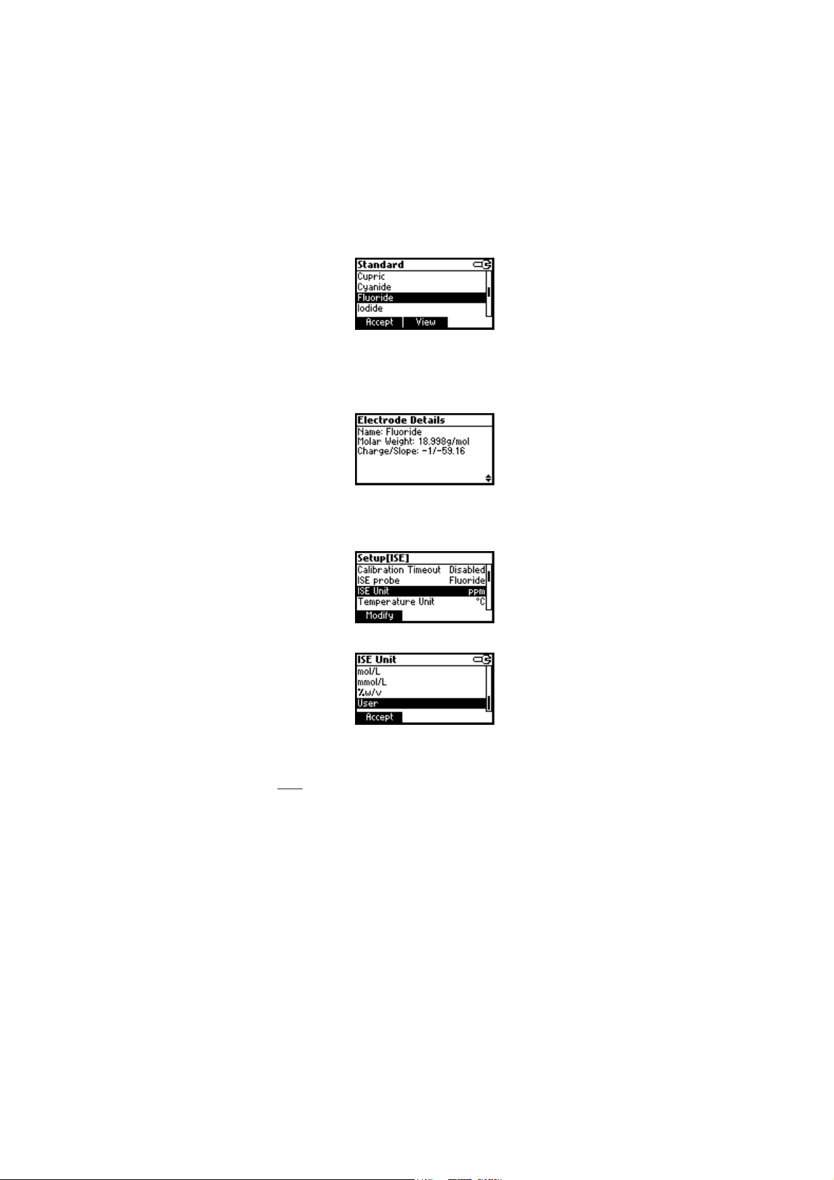
If Standard was pressed.
Use ARROW keys to focus on the desired electrode.
Press Accept to confirm setting or ESC to exit.
Press View to see probe parameters.
ISE unit
Focus on the
Press Modify.
ISE Unit
item.
Use ARROW key to select unit.
Press Accept to confirm selection or ESC to exit.
Notes: • If the unit is changed or “User” is selected a warning
message will be displayed to alert that the ISE range must
be calibrated.
• If a new probe was selected or custom probe parameter are
changed, the ISE range must be calibrated.
51
Page 52

EC CHANNEL RANGE SPECIFIC PARAMETERS
Calibration Timeout
Focus on the
Press Modify.
Use ARROW keys to set desired value.
Press Accept to confirm or ESC to return without saving.
Note: If enabled “CAL DUE” warning will be displayed, the set number
Out of Calibration Range Warning
Focus on
Calibration Timeout
of days after calibration is over passed.
Out of Cal. Range Warning
item.
item.
Press the corresponding functional key in order to enable/disable this
feature. If enabled, a warning message is displayed when the EC reading
is too far from the EC calibration points.
Temperature compensation
Focus on
T. Compensation
Press one of the selected functional keys to change the option.
item.
52
Page 53

Select No TC in order to display actual conductivity (no temperature
compensation).
Select MTC in order to automatically compensate conductivity using the
set temperature coefficient with the temperature manually selected by
the user.
Select ATC in order to automatically compensate conductivity using the
set temperature coefficient with the temperature read from the sensor
inside the EC probe.
Range Select
Focus on the
Press Modify to select ranging mode.
Use the ARROW keys to change selection.
Press Accept to confirm or ESC to exit without saving. If “Automatic” is
selected the instrument changes the range automatically according with
the input.
If one of the range is selected all the readings are displayed on the
corresponding range.
The readings will be displayed with maximum 6 digits. If the reading
exceeds the maximum number of digits for the fixed range, the maximum
value is displayed blinking.
Note: The Range Select parameter can be set only in EC, resistivity and
Cell constant
Focus on the
Range Select
TDS range.
Cell Constant
item.
item.
Press Modify to change the cell constant value.
53
Page 54
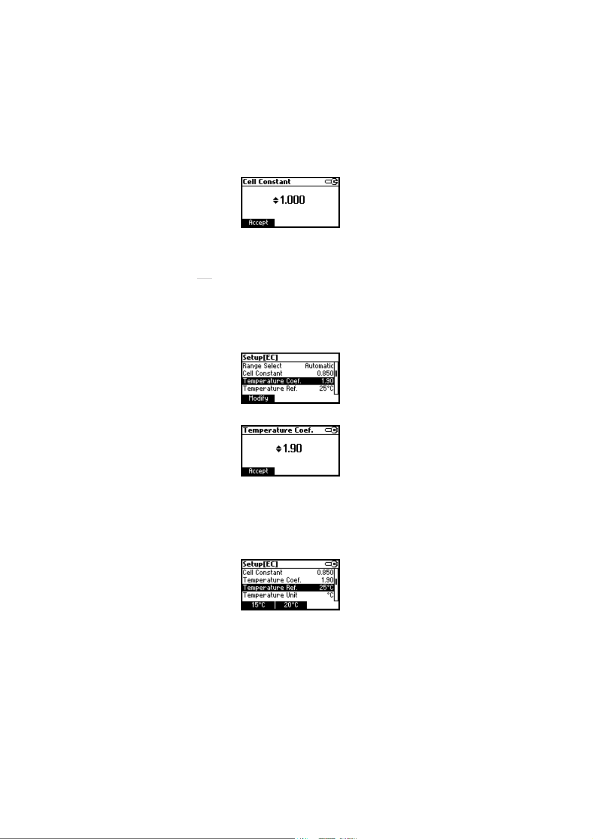
Use ARROW keys to change the cell constant value.
Press Accept to confirm or ESC to exit without changing.
Note: If the cell constant value is modified, the EC slope calibration is
deleted and the NaCl calibration is deleted. If performed, the EC
offset calibration remains active.
Temperature Coefficient
Focus on the
Press Modify in order to set the temperature coefficient.
Use the ARROW keys to change the value.
Press Accept to confirm or ESC to exit without changing.
Temperature Reference
Focus on the
Temperature Coef.
Temperature Ref.
item.
item.
Press the corresponding functional key to select the desired reference
temperature.
54
Page 55

LOGGINGLOGGING
LOGGING
LOGGINGLOGGING
This feature allows the user to log pH, Rel mV, ISE, EC, TDS, NaCl or
Resistivity measurements. All logged data can be transferred to a PC
through the USB port.
The logging space includes 400 records of Log on demand and 600
records of Log interval (lot logging). The log interval is organized in lots.
A maximum of 100 lots are accepted. One lot can occupy all the memory
space available.
LOGGING THE CURRENT DATA
To store the current reading into memory, press Log while in measurement
mode.
The instrument will display for few seconds the record number and the
amount of the free log space.
If the LOG space is full, the “Log space is full” message will be displayed
for few seconds when Log key is pressed. Enter View Logged Data Mode
and delete records in order to free log space.
LOT LOGGING
Select the desired interval in SETUP as a timed interval or AutoEnd waits
for a stable value before logging.
Press the StartLog function key in order to start Log interval.
Press the StopLog function key in order to stop logging and close current lot.
55
Page 56
Notes: • At Power Off the current lot is automatically closed.
• If the 600 records space or 100 lots are reached, the “AutoLog
space is full” message will be displayed.
• Enter View Log Data mode and delete lots in order to free
space.
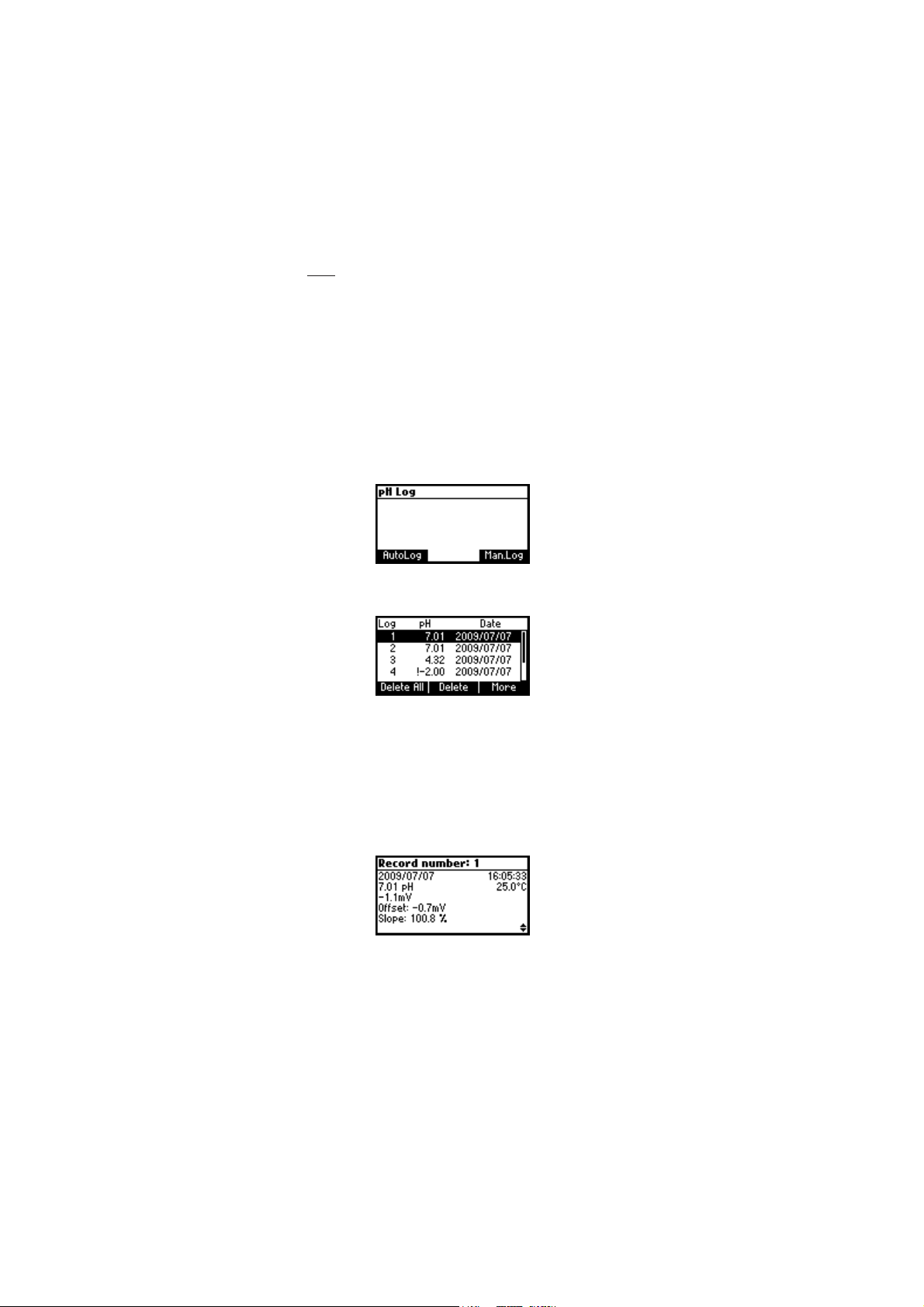
VIEW LOGGED DATA
Press the Recall function key to retrieve the information stored while in
measurement mode for the specific range. If the Recall function key is not
displayed press MENU key.
The Recall selection screen is displayed.
Press the corresponding function key to view the records.
If Man.Log is pressed, the list of records is displayed.
If no data were logged, the instrument will display “No Records”
message.
Use ARROW keys to scroll between the records from the list.
Press Delete All to enter
Press Delete to enter
Press More to view more information of the focused record.
If More is pressed.
Delete All
Delete records
screen.
screen.
Use ARROW keys to scroll between complete log information.
56
Page 57
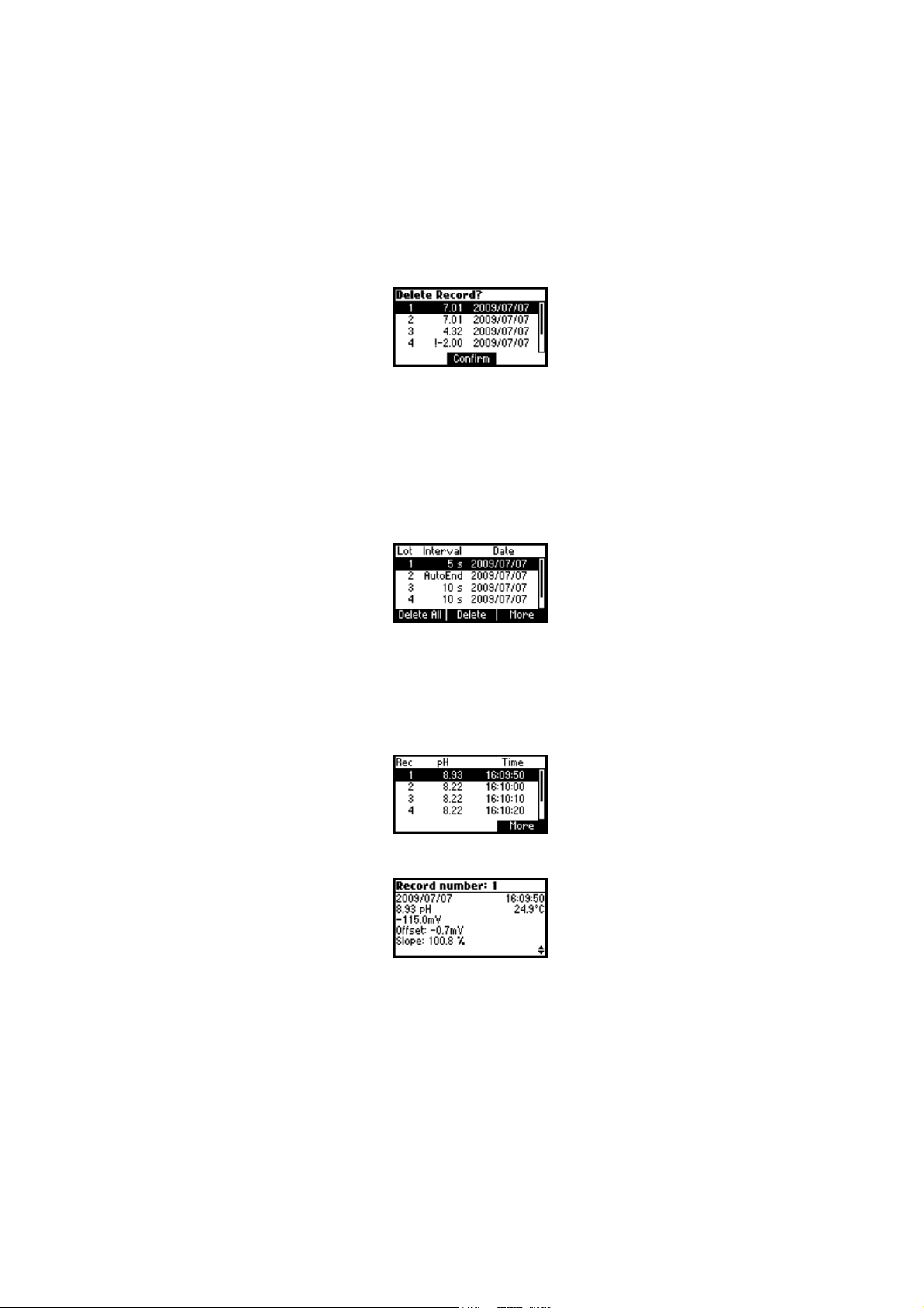
If Delete is pressed.
Use ARROW key to focus the record to be deleted and then press
Confirm.
Press ESC to exit.
If Delete All is pressed the instrumet asks for confirmation.
Press Confirm to confirm or ESC to exit without deleting.
If AutoLog is pressed, the lot information of the specific range are
displayed.
Use the ARROW keys to scroll the lots.
Press the Delete All function key to enter the
Press the Delete function key to enter the
Press the More function key to view the records information of the focused
lot.
Delete All lots
Delete lot
screen.
screen.
If More is pressed.
57
Page 58

mm
V CALIBRATIONV CALIBRATION
m
V CALIBRATION
mm
V CALIBRATIONV CALIBRATION
(for technical personnel only)
All the instruments are factory calibrated for mV, EC and temperature.
Hanna’s temperature probes are interchangeable and no temperature
calibration is needed when they are replaced.
If the temperature or ORP measurements are inaccurate, calibration
should be performed.
For an accurate recalibration, contact your dealer or the nearest Hanna
Customer Service Center, or follow the instructions below.
mV CALIBRATION
• With the instrument off press and hold down the CHANNEL and
keys and then power on the instrument. The meter will enter mV
calibration mode.
A two point calibration can be performed at 0 mV and 1800 mV.
• Attach to the BNC connector a mV simulator with an accuracy of
±0.1 mV.
• Enter the calibration screen. Press mV function key.
• Set 0.0 mV on the simulator.
• When the reading is stable and close to the selected calibration
point, the Confirm function key is displayed.
• Press Confirm to confirm. The second calibration point of “1800 mV”
will be displayed.
• Set 1800.0 mV on the simulator.
• When the reading is stable and close to the selected calibration
point, the Confirm function key is displayed.
• Press Confirm to confirm. The instrument will restart and the
calibration will be memorized.
Notes: • If the reading is not close to the selected calibration point,
“Wrong” tag will blink. Verify calibration condition or contact
your vendor if you cannot calibrate.
• Press ESC in any moment of the calibration process. The
instrument will restart and no calibartion will be memorized.
58
Page 59

TEMPERATURE CALIBRATIONTEMPERATURE CALIBRATION
TEMPERATURE CALIBRATION
TEMPERATURE CALIBRATIONTEMPERATURE CALIBRATION
(for technical personnel only)
• Press CAL key on the pH range or on the EC range. The calibration
screen is displayed. Press Temp function key to enter the temperature
calibration mode. The temperature calibration is performed for the
current channel only. The calibration routine is the same for both
channels, so Ch1 calibration is presented next.
• Prepare a vessel containing ice and water and another one containing
hot water (at approximately
material around the vessels to minimize temperature changes.
• Use a calibrated thermometer with a resolution of 0.1 ºC as a
reference thermometer. Connect the temperature probe or the EC
probe to the appropriate socket.
50 ºC or 122 ºF). Place insulation
• Immerse the temperature probe or the EC probe including temperature
sensor into the vessel with ice and water as close as possible to the
reference thermometer. Allow a few seconds for the probe to stabilize.
• Use the ARROW keys to set the calibration point value to that of ice
and water mixture, measured by the reference thermometer. When
the reading is stable and close to the selected calibration point, the
Confirm function key is displayed.
• Press Confirm to confirm.
• The second expected calibrated point is displayed.
• Immerse the temperature probe into the second vessel as close as
possible to the reference thermometer. Allow a few seconds for the
probe to stabilize.
59
Page 60
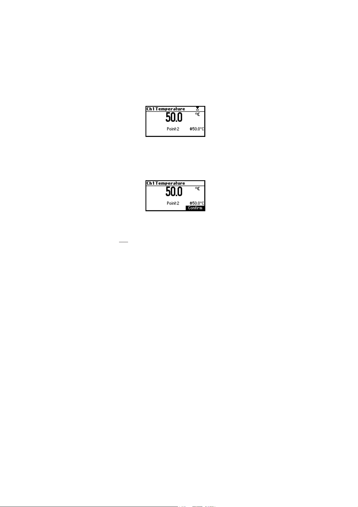
• Use the ARROW keys to set the calibration point value to that of the
hot water.
• When the reading is stable and close to the selected calibration
point, Confirm function key is displayed.
• Press Confirm to confirm. The instrument returns to the calibration
screen.
Note: Use ARROW keys to change calibration point if necessary
(±10.0 ºC) around the point.
If the reading is not close to the selected calibration point, “Wrong”
message will blink. Change the temperature probe and restart calibration.
60
Page 61

PC INTERFACEPC INTERFACE
PC INTERFACE
PC INTERFACEPC INTERFACE
Data transmission from the instrument to the PC can be done with the
HI 92000 Windows® compatible software (optional). HI 92000 also
offers graphing and on-line help feature.
Data can be exported to the most popular spreadsheet programs for
further analysis.
To connect your instrument to a PC, use an USB cable connector. Make
sure that your instrument is switched off and plug one connector to the
instrument USB socket and the other to the serial or USB port of your PC.
Note: If you are not using Hanna Instruments HI 92000 software,
please see the following instructions.
SENDING COMMANDS FROM PC
It is also possible to remotely control the instrument with any terminal
program. Use an USB cable to connect the instrument to a PC, start the
terminal program and set the communication options as follows: 8, N, 1,
no flow control.
COMMAND TYPES
To send a command to the instrument follow the next scheme:
<command prefix> <command> <CR>
where: <command prefix> is the 16 ASCII character
<command> is the command code.
Note: Either small or capital letters can be used.
SIMPLE COMMANDS
KF1 Is equivalent to pressing function key 1
KF2 Is equivalent to pressing function key 2
KF3 Is equivalent to pressing function key 3
RNG Is equivalent to pressing RANGE key
CAL Is equivalent to pressing CAL key
UPC Is equivalent to pressing the UP arrow key
DWC Is equivalent to pressing the DOWN arrow key
MNU Is equivalent to pressing MENU key
ESC Is equivalent to pressing ESC key
61
Page 62

CHRxx Change the instrument range according with the parameter
value (xx):
• xx=10 pH range/0.001 resolution on channel 1
• xx=11 pH range/0.01 resolution on channel 1
• xx=12 pH range/0.1 resolution on channel 1
• xx=13 mV range on channel 1
• xx=14 Relative mV range on channel 1
• xx=15 ISE range on channel 1
• xx=20 EC range on channel 2
• xx=21 Resistivity range on channel 2
• xx=22 TDS range on channel 2
• xx=23 Salinity range on channel 2
The instrument will answer for these commands with:
<STX> <answer> <ETX>
where: <STX> is 02 ASCII code character (start of text)
<ETX> is 03 ASCII code character (end of text)
<answer>:
<ACK> is 06 ASCII code character (recognized command)
<NAK> is 21 ASCII code character (unrecognized com-
mand)
<CAN> is 24 ASCII code character (corrupted command)
COMMANDS REQUIRING AN ANSWER
The instrument will answer for these commands with:
<STX> <answer> <checksum> <ETX>
where the checksum is the bytes sum of the answer string sent as 2 ASCII
characters.
All the answer messages are with ASCII characters.
RAS Causes the instrument to send a complete set of readings in
according with the current range:
• pH, mV reading and temperature on pH range.
• mV and temperature reading on mV range
• Rel mV, absolute mV and temperature reading on
Rel mV range.
• concentration, mV and temperature reading on ppm
range.
• EC and temperature reading on the EC range
62
Page 63

• Resistivity, EC and temperature reading on the
Resistivity range
• TDS, EC and temperature reading on the Resistivity
range
• Salinity, EC and temperature reading on the
Resistivity range
The answer string contains:
• Meter mode (2 chars):
• 10 pH range/0.001 resolution on channel 1
• 11 pH range/0.01 resolution on channel 1
• 12 pH range/0.1 resolution on channel 1
• 13 mV range on channel 1
• 14 Relative mV range on channel 1
• 15 ISE range on channel 1
• 20 EC range on channel 2
• 21 Resistivity range on channel 2
• 22 TDS range on channel 2
• 23 Salinity range on channel 2
• Meter status (2 chars of status byte): represents a 8
bit hexadecimal encoding.
• 0x10 - temperature probe is connected
• 0x01 - new GLP data available
• 0x02 - new SETUP parameter
• 0x04 - out of calibration range
• 0x08 - the meter is in autoend point mode
• Reading status (2 chars): R - in range, O - over
range, U - under range. First character corresponds
to the primary reading. Second character corresponds
to the second reading (if second reading exists).
• The unit of the reading (2 chars) (for ISE, EC, Resistivity, TDS, Salinity ranges only)
• for ISE range it represent the index of the unit
selected from setup (0-ppt, 11-User)
• for EC range: 0 - microsiemens, 1 - milisiemens
• for TDS range: 0 - ppm, 1 - g/L
• for Salinity range the unit represents always %
• Primary reading (corresponding to the selected range)
- 12 ASCII chars, including sign and decimal point
and exponent.
63
Page 64

• The unit of the second reading (1 char) (it is sent
only for Resistivity, TDS and Salinity ranges only). It
represents the unit of the EC reading (0 - microsiemens,
1 - milisiemens)
• Secondary reading (only when primary reading is
not mV or EC) - 8 ASCII chars, including sign and
decimal point.
• Temperature reading - 7 ASCII chars, with sign and
decimal point, always in ºC.
MDR Requests the instrument model name and firmware code
(16 ASCII chars).
GLPx Requests the calibration data record.
• x=1 calibration data from channel 1
• x=2 calibration data from channel 2
The answer string contains:
• GLP status (1 char): represents a 4 bit hexadecimal
encoding.
• 0x01 - pH calibration available (Ch1) or EC
calibration available (Ch2)
• 0x02 - Rel mV calibration available (Ch1) or
Salinity calibration available (Ch2)
• 0x04 - ISE calibration available
Channel 1 GLP
• pH calibration data (if available), which contains:
• the number of calibrated buffers (1 char)
• the offset, with sign and decimal point (7 chars)
• the average of slopes, with sign and decimal
point (7 chars)
• the calibration time, yymmddhhmmss (12 chars)
• buffers information (for each buffer)
• type (1 char): 0 - standard, 1 - custom
• status (1 char): N (new) - calibrated in last
calibration; O (old) - from an old calibration.
• warnings during calibration (2 chars): 00 no warning, 04 - Clean Electrode warning
• buffer value, with sign and decimal point and
exponent (12 chars)
• the calibration time of the buffer, yymmdd
hhmmss (12 chars).
64
Page 65

• electrode condition, with sign (3 chars). The
“-01” code means not calculated
• ISE calibration data (if available) which contains:
• the number of calibrated standards (1 char)
• the ISE unit (2 chars)
• the calibration slope, with sign and decimal point
(7 chars)
• the calibration time of the standard, yymmdd
hhmmss (12 chars)
• standards information (for each standard)
• type (1 char): 0 - always standard solution
• status (1 char): N (new) - calibrated in last
calibration; O (old) - from an old calibration
• warnings during calibration (2 chars): 00 -
no warning
• standard value, with sign and decimal point
and exponent (12 chars)
• calibration time, yymmddhhmmss (12 chars)
• Rel mV calibration data (if available), which contains:
• the calibration offset, with sign (7 chars)
• the calibration time, yymmddhhmmss (12 chars)
Channel 2 GLP
• EC calibration data (if available), which contains:
• the number of calibrated standards (1 char)
• the offset, with sign and decimal point (7 chars)
• the cell constant, with sign and decimal point (7 chars)
• the calibration time, yymmddhhmmss (12 chars)
• standards information (for each buffer)
• the unit of the standard (0 - microsiemens,
1 - milisiemens)
• the standard value, with sign, decimal
point and exponont (11 chars)
• the calibration time of the standard,
yymmddhhmmss (12 chars)
• the temperature reference value (2 chars)
• the temperature compensation mode (2 chars:
00 - NoTC, 01 - MTC, 02 - ATC)
• the temperature compensation coefficient, with
65
Page 66

sign and decimal point (6 chars)
• Salinity calibration data (if available), which contains:
• the number of calibrated standards (1 char always 1)
• the salinity factor, with sign and decimal point
(7 chars)
• calibration time, yymmddhhmmss (12 chars)
PARx Requests the setup parameters setting.
• x=1 setup parameters for channel 1
• x=2 setup parameters for channel 2
The answer string contains:
• Lot log interval index (2 ASII chars - it represents
the index from the setup list for the log interval)
• Backlight Value (1 ASCII char)
• Contrast Value (2 ASCII char)
• Instrument ID (4 chars)
Channel 1 data
• Calibration Alarm time out for pH (2 chars)
• Calibration Alarm timeout for ISE (2 chars)
• SETUP information (2 chars): 8 bit hexadecimal
encoding.
• 0x01 - beep ON (else OFF)
• 0x02 - degrees Celsius (else degrees Fahrenheit)
• 0x04 - Offset calibration (else Point calibration)
• The number of pH custom buffers (1 char)
• The custom buffer values, with sign and decimal
point, for each defined custom buffer (7 chars)
• The ID of the ISE electrode (2 chars) (standard or
custom)
• The molar weight of the selected ION, with sign and
decimal point (9 ASCII characters)
• The electrode slope (6 ASCII chars)
• The ion charge (2 chars)
• The ISE unit (2 chars)
• The short name of the selected language (3 chars)
Channel 2 data
• Calibration alarm timeout for the EC (2 chars)
• Calibration alarm timeout for the Salinity (2 chars)
• Setup information (2 chars): 8 bit hexadecimal
66
Page 67

encoding
• 0x01 - beep ON (else OFF)
• 0x02 - degrees Celsius (else Fahrenheit)
• 0x04 and 0x08 - this 2 bits represent the
temperature compensation mode (10 - ATC,
01 - MTC, 00 - NoTC)
• The cell constant, with sign and decimal point (7 chars)
• The temperature compensation coefficient, with sign
and decimal point (6 chars)
• The temperature reference value (2 chars)
• The TDS factor, with sign and decimal point (5 chars)
• The short name of the selected language (3 chars)
NSLxy Requests the number of logged samples (4 chars).
The command parameter (2 chars):
• x=1 request for channel 1
• x=2 request for channel 2
• y=P request for pH range
• y=M request for mV and Rel mV ranges
• y=I request for ISE range
• y=E request for EC range
• y=R request for Resistivity range
• y=T request for TDS ranges
• y=N request for NaCl range
LLSxy Requests the number of lots (information about lots) on the specified
channel and range (x - channelnumber; y - range first letter)
• x=1 request for channel 1
• x=2 request for channel 2
• y=P request for pH range
• y=M request for mV and Rel mV ranges
• y=I request for ISE range
• y=E request for EC range
• y=R request for Resistivity range
• y=T request for TDS ranges
• y=N request for NaCl range
The answer string contains:
• number of lots (3 chars)
For each lot:
• the lot number (3 chars)
• the number of records in lot (3 chars)
67
Page 68

• the log interval (5 chars): the value is in seconds; for
AutoEnd log the value sent is 11000
• the log starting time, yymmddhhmmss (12 chars)
GLDxyqqq Requests all records of the qqqth lot from the specified chan-
nel and range (x - channel number; y - range first letter).
The command parameter (5 chars):
• x=1 request for channel 1
• x=2 request for channel 2
• y=P request for pH range
• y=M request for mV and Rel mV ranges
• y=I request for ISE range
• y=E request for EC range
• y=R request for Resistivity range
• y=T request for TDS ranges
• y=N request for NaCl range
• qqq=the qqqth lot of the requested range
The answer string contains:
• Log header data:
• The log type (2 chars)
• The lot number (3 chars)
• The number of records in lot (3 chars)
• The log the log interval (5 chars): the value is in
seconds; for AutoEnd log the value sent is 11000
• The offset, with sign and decimal point (7 chars)
(not available for ISE log)
• The slope for Channel 1 and the cell constant for
Cannel 2, with sign and decimal point (7 chars)
(not available for Rel mV log)
For Channel 2 only
• The TDS factor (for the TDS log only) or the
salinity factor (for the Salinity log only), with sign
and decimal point (6 chars)
• The temperature reference value (2 chars)
• The temperature compensation mode (2 chars)
• The temperature compensation coefficient, with
sign and decimal point (6 chars)
For both Channels
• The log starting time, yymmddhhmmss (12 chars)
68
Page 69

• For each record:
• The number of the record (3 chars)
• The reading status (1 char): R, O, U
• The unit of the reading (2 chars): it is sent only
for ISE, EC, Resistivity, TDS, Salinity log only
• The calculated reading, with sign, decimal point
and exponent (12 chars)
• The temperature reading, with sign and decimal
point (7 chars)
• The second reading status (1 char): R, O, U; not
available for EC log
• The second unit of the reading (2 chars); it is sent
only for Resistivity, TDS and Salinity log only
• The second reading, with sign and decimal point
(8 chars); not available for EC log
• The logging time (6 chars): it is sent only for
AutoEnd log
• The temperature probe persence (1 char)
LODxPyyy Requests the yyyth pH record logged data when x=1
LODxMyyy Requests the yyyth mV/Rel mV record logged data when x=1
LODxIyyy Requests the yyyth ISE record logged data when x=1
LODxEyyy Requests the yyyth EC record logged data when x=2
LODxRyyy Requests the yyyth Resistivity record logged data when x=2
LODxTyyy Requests the yyyth TDS record logged data when x=2
LODxNyyy Requests the yyyth Salinity record logged data when x=2
LODxPALL Requests all pH Log on demand when x=1
LODxMALL Requests all mV/Rel mV Log on demand when x=1
LODxIALL Requests all ISE Log on demand when x=1
LODxEALL Requests all EC Log on demand when x=2
LODxRALL Requests all Resistivity Log on demand when x=2
LODxTALL Requests all TDS Log on demand when x=2
LODxNALL Requests all Salinity Log on demand when x=2
The answer string contains:
• The number of records (3 chars): this is sent only is
“ALL” data is requested
• The log type (2 chars)
• The number of the record (3 chars)
69
Page 70

• The reading status (1 char): R, O, U
• The unit of the reading (2 chars): it is sent only for
ISE, EC, Resistivity, TDS, Salinity log
• The calculated reading, with sign, decimal point
and exponent (12 chars)
• The temperature reading, with sign and decimal
point (7 chars)
• The reading status (1 char): R, O, U; not available
for EC log
• The second unit of the second reading (2 chars); it is
sent only for Resistivity, TDS and Salinity log
• The second reading, with sign and decimal point
(8 chars); not available for EC log
• The logged time, yymmddhhmmss (12 chars)
• The offset, with sign and decimal point (7 chars)
(not available for ISE log)
• The slope for Channel 1 and the cell constant for
Channel 2, with sign and decimal point (7 chars)
(not available for Rel mV log)
• The temperature probe presence (1 char)
For channel 2 only
• The TDS factor (for the TDS log only) or the salinity
factor (for the salinity log only), with sign and decimal
point (6 chars)
• The temperature reference value (2 chars)
• The temperature compensation mode (2 chars)
• The temperature compensation coefficient, with sign
and decimal point (6 chars)
Notes: • “Err3” is sent if the Log on demand is empty.
• “Err4” is sent if the requested parameter is not available.
• “Err6” is sent if the requested range is not available.
• “Err8” is sent if the instrument is not in measurement mode.
• Invalid commands will be ignored.
70
Page 71
TEMPERATURE CORRELATIONTEMPERATURE CORRELATION
TEMPERATURE CORRELATION
TEMPERATURE CORRELATIONTEMPERATURE CORRELATION
FOR FOR
pp
FOR
FOR FOR
The resistance of glass electrodes partially depends on the temperature. The
lower the temperature, the higher the resistance. It takes more time for the
reading to stabilize if the resistance is higher. In addition, the response time
will suffer to a greater degree at temperatures below 25 ºC (77 ºF).
Since the resistance of the pH electrode is in the range of 50 – 200 Mohm,
the current across the membrane is in the pico Ampere range. Large
currents can disturb the calibration of the electrode for many hours.
For these reasons high humidity environments, short circuits and static
discharges are detrimental to a stable pH reading.
The pH electrode’s life also depends on the temperature. If constantly
used at high temperatures, the electrode life is drastically reduced.
Typical Electrode Life
Ambient Temperature 1 – 3 years
90 ºC (194 ºF) Less than 4 months
120 ºC (248 ºF) Less than 1 month
Alkaline Error
High concentrations of sodium ions interfere with readings in alkaline
solutions. The pH at which the interference starts to be significant
depends upon the composition of the glass. This interference is called
alkaline error and causes the pH to be underestimated. Hanna’s glass
formulations have the indicated characteristics.
H SENSITIVE GLASSH SENSITIVE GLASS
p
H SENSITIVE GLASS
pp
H SENSITIVE GLASSH SENSITIVE GLASS
Sodium Ion Correction for the Glass at 20-25 ºC (68-77 ºF)
Concentration pH Error
0.1 Mol L-1 Na
1.0 Mol L-1 Na
+
+
13.00
13.50
14.00
12.50
13.00
13.50
14.00
71
0.10
0.14
0.20
0.10
0.18
0.29
0.40
Page 72
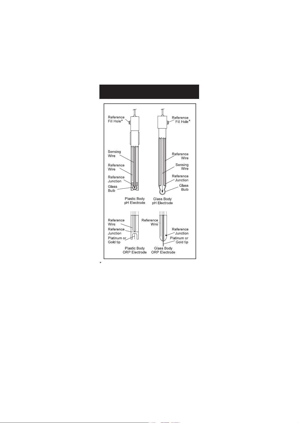
ELECTRODE CONDITIONINGELECTRODE CONDITIONING
ELECTRODE CONDITIONING
ELECTRODE CONDITIONINGELECTRODE CONDITIONING
& MAINTENANCE& MAINTENANCE
& MAINTENANCE
& MAINTENANCE& MAINTENANCE
Not present in gel electrodes.
PREPARATION PROCEDURE
Remove the electrode protective cap.
DO NOT BE ALARMED IF ANY SALT DEPOSITS ARE PRESENT. This is
normal with electrodes and they will disappear when rinsed with water.
During transport tiny bubbles of air may have formed inside the glass
bulb. The electrode cannot function properly under these conditions.
These bubbles can be removed by "shaking down" the electrode as you
would do with a glass thermometer.
If the bulb and/or junction are dry, soak the electrode in HI 70300
Storage Solution for at least one hour. Open the fill hole if refillable.
72
Page 73

For refillable electrodes:
If the filling solution (electrolyte) is more than 2½ cm (1”) below the fill
hole, add HI 7082 or HI 8082 3.5M KCl Electrolyte Solution for double
junction or HI 7071 or HI 8071 3.5M KCl+AgCl Electrolyte Solution for
single junction electrodes.
For faster response, unscrew the fill hole screw during measurements.
For AmpHel® electrodes:
If the electrode does not respond to pH changes, the battery has run
down and the electrode should be replaced.
MEASUREMENT
Rinse the pH electrode tip with distilled or deionized water. Immerse the
tip 3 cm (1¾”) in the sample and stir gently for a few seconds.
For a faster response and to avoid cross-contamination of the samples,
rinse the electrode tip with a few drops of the solution to be tested, before
taking measurements.
See that the sleeve holes of the ORP probe are completly submersed.
STORAGE PROCEDURE
To minimize clogging and assure a quick response time, the glass bulb
and the junction of pH electrode should be kept moist and not allowed to
dry out.
Replace the solution in the protective cap with a few drops of HI 70300
or HI 80300 Storage Solution or, in its absence, Filling Solution
(HI 7071 or HI 8071 for single junction and HI 7082 or HI 8082 for
double junction electrodes). Follow the Preparation Procedure on page
72 before taking measurements.
Note: NEVER STORE THE ELECTRODE IN DISTILLED OR DEIONIZED WATER.
PERIODIC MAINTENANCE
Inspect the electrode and the cable. The cable used for connection to the
instrument must be intact and there must be no points of broken
insulation on the cable or cracks on the electrode stem or bulb. Connectors
must be perfectly clean and dry. If any scratches or cracks are present,
replace the electrode. Rinse off any salt deposits with water.
pH Probe Maintenance
For refillable electrodes:
Refill the reference chamber with fresh electrolyte (HI 7071 or HI 8071 for
single junction or HI 7082 or HI 8082 for double junction electrodes).
Allow the electrode to stand upright for 1 hour.
73
Page 74

Follow the Storage Procedure above.
pH CLEANING PROCEDURE
•
General
•
Protein
•
Inorganic
•
Oil/grease
IMPORTANT: After performing any of the cleaning procedures, rinse the
electrode thoroughly with distilled water, refill the reference chamber
with fresh electrolyte (not necessary for gel-filled electrodes) and soak the
electrode in HI 70300 or HI 80300 Storage Solution for at least 1 hour
before calibrating.
Soak in Hanna HI 7061 or HI 8061 General
Cleaning Solution for approximately ½ hour.
Soak in Hanna HI 7073 or HI 8073 Protein
Cleaning Solution for 15 minutes.
Soak in Hanna HI 7074 Inorganic Cleaning
Solution for 15 minutes.
Rinse with Hanna HI 7077 or HI 8077 Oil
and Fat Cleaning Solution.
74
Page 75

ECEC
PROBE MAINTENANCE PROBE MAINTENANCE
EC
PROBE MAINTENANCE
ECEC
PROBE MAINTENANCE PROBE MAINTENANCE
Rinse the probe with clean water after measurements. If more cleaning
is required, remove the probe sleeve and clean the probe with a cloth or
a nonabrasive detergent. Make sure to reinsert the sleeve onto the probe
properly and in the right direction. After cleaning the probe, recalibrate
the instrument.
The platinum rings are sustained with glass. Take great care while
handling the probe.
75
Page 76

SMOTPMYS MELBORP NOITULOS
evissecxe/esnopserwolS
.tfird
.edortceleHpytriD nipitedortceleehtkaoS
1607IH noitulosgninaelc
htiwllifeR.setunim03rof
.noitulosllif
dnapusetautculfgnidaeR
.)esion(nwod
.noitcnujytrid/deggolC
leveletylortcelewoL
sedortceleelballifer(
.)ylno
ylreporptoneborpCE
.detcennoc
ees(edortceleehtnaelC
.)evoba
etylortcelehserfhtiwllifeR
.)ylnosedortceleelballifer(
.eborpehttresnI
gniknilbswohsyalpsiD
.eulavelacslluf
.egnarfotuognidaeR nihtiwsielpmastahtkcehC
;egnarelbarusaem
dnaleveletylortcelekcehC
.sutatsedortcelelareneg
;retemehtetarbilaceR
dexiftonsiegnarehtkcehC
.dekcolro
.egnarfotuoelacsVm yrdroenarbmemyrD
.noitcnuj
niedortcelekaoS 00307IH
tsaeltarofnoitulosegarots
.setunim03
lobmysswohsyalpsiD
erutarepmetfotnorfni
.gnidaer
gnissimroredrofotuO
.eborperutarepmet
eborperutarepmetecalpeR
.noitcennocehtkcehcro
swohsyalpsiD naelC“
“edortcele .gniknilb
wenneewtebecnereffiD
suoiverpdna
neebsahnoitarbilac
.detceted
dnaedortcelenaelC
melborpehtfI.etarbilacer
reffubehtkcehc,sniamer
.snoitulos
htiwkrowtonseodreteM
.eborperutarepmet
erutarepmetnekorB
.eborp
.eborperutarepmetecalpeR
roetarbilacotsliafreteM
.sgnidaerytluafsevig
.edortcelenekorB .edortceleecalpeR
retemehtputratstA
sgatogoLannaHsyalpsid
.yltnenamrep
sisyekehtfoenO
.dekcolb
ynatarelaedruoytcatnoC
ecivreSstnemurtsnIannaH
.retneC
erasegassemrorrE
Hpgniruddeyalpsid
.erudecorpnoitarbilac
detanimatnocrognorW
roytridedortcele,reffub
.nekorb
sinoitulosreffubtahtkcehC
ehtdna,hserfdnatcerroc
tcerrocehtroftessiretem
.reffub
“ xxrrE taegassem”
.putrats
.rorrelanretnI ynarorelaedruoytcatnoC
.retneCecivreSannaH
TROUBLESHOOTING GUIDETROUBLESHOOTING GUIDE
TROUBLESHOOTING GUIDE
TROUBLESHOOTING GUIDETROUBLESHOOTING GUIDE
76
Page 77

ACCESSORIESACCESSORIES
ACCESSORIES
ACCESSORIESACCESSORIES
pH CALIBRATION SOLUTIONS
HI 50004-01 pH 4.01 Buffer Solution, 20 mL sachet, 10 pcs
HI 50004-02 pH 4.01 Buffer Solution, 20 mL sachet, 25 pcs
HI 50007-01 pH 7.01 Buffer Solution, 20 mL sachet, 10 pcs
HI 50007-02 pH 7.01 Buffer Solution, 20 mL sachet, 25 pcs
HI 50010-01 pH 10.01 Buffer Solution, 20 mL sachet, 10 pcs
HI 50010-02 pH 10.01 Buffer Solution, 20 mL sachet, 25 pcs
HI 5016 pH 1.68 Buffer Solution, 500 mL bottle
HI 5004 pH 4.01 Buffer Solution, 500 mL bottle
HI 5068 pH 6.86 Buffer Solution, 500 mL bottle
HI 5007 pH 7.01 Buffer Solution, 500 mL bottle
HI 5091 pH 9.18 Buffer Solution, 500 mL bottle
HI 5010 pH 10.01 Buffer Solution, 500 mL bottle
HI 5124 pH 12.45 Buffer Solution, 500 mL bottle
HI 8004L pH 4.01 Buffer Solution in FDA approved bottle, 500 mL
HI 8006L pH 6.86 Buffer Solution in FDA approved bottle, 500 mL
HI 8007L pH 7.01 Buffer Solution in FDA approved bottle, 500 mL
HI 8009L pH 9.18 Buffer Solution in FDA approved bottle, 500 mL
HI 8010L pH 10.01 Buffer Solution in FDA approved bottle, 500 mL
ELECTRODE STORAGE SOLUTION
HI 70300L Storage Solution, 500 mL bottle
HI 80300L Storage Solution in FDA approved bottle, 500 mL
ELECTRODE CLEANING SOLUTIONS
HI 70000P Electrode Rinse Solution, 20 mL sachet, 25 pcs
HI 7061L General Purpose Solution, 500 mL bottle
HI 7073L Protein Cleaning Solution, 500 mL bottle
HI 7074L Inorganic Cleaning Solution, 500 mL bottle
HI 7077L Oil & Fat Cleaning Solution, 500 mL bottle
HI 8061L General Purpose Solution in FDA approved bottle, 500 mL
HI 8073L Protein Cleaning Solution in FDA approved bottle, 500 mL
HI 8077L Oil & Fat Cleaning Solution in FDA approved bottle, 500 mL
ELECTRODE REFILL ELECTROLYTE SOLUTIONS
HI 7071 3.5M KCl+AgCl Electrolyte for single junction electrodes
HI 7072 1M KNO3 Electrolyte
HI 7082 3.5M KCl Electrolyte for double junction electrodes
HI 8071 3.5M KCl + AgCl Electrolyte in FDA approved bottle,
4x30 mL, for single junction electrodes
HI 8072 1M KNO3 Electrolyte in FDA approved bottle, 4x30 mL
77
Page 78
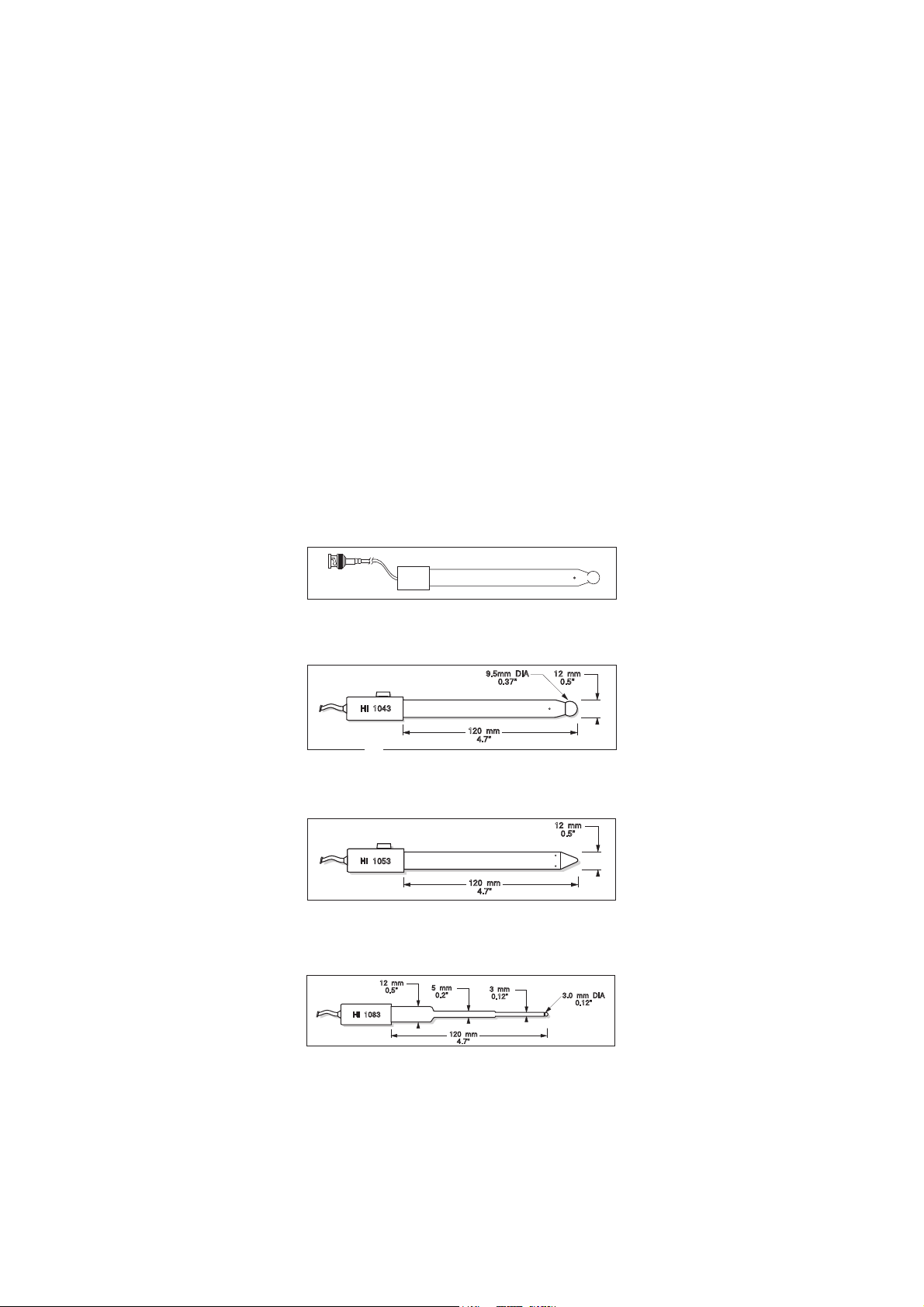
120 mm
12 mm
0.5"
5 mm
0.2"
3 mm
0.12"
3.0 mm DIA
0.12"
HI 1083
120 mm
4.7"
12 mm
0.5"
"S" VERSION
HI 1053
120 mm
4.7"
12 mm
0.5"
9.5mm DIA
0.37"
"S" VERSION
HI 1043
HI 8082 3.5M KCl Electrolyte in FDA approved bottle, 4x30 mL,
for double junction electrodes
HI 8093 1M KCl+AgCl Electrolyte in FDA approved bottle, 4x30 mL
ORP PRETREATMENT SOLUTIONS
HI 7091L Reducing Pretreatment Solution, 500 mL bottle
HI 7092L Oxidizing Pretreatment Solution, 500 mL bottle
ORP SOLUTIONS
HI 7020L Test Solution 200-275 mV, 500 mL bottle
HI 7021L Test Solution 240 mV, 500 mL bottle
HI 7022L Test Solution 470 mV, 500 mL bottle
pH ELECTRODES
All electrodes part numbers ending in B are supplied with a BNC connector
and 1 m (3.3') cable, as shown below:
HI 1043B
Glass-body, double junction, refillable, combination pH electrode.
Use: strong acid/alkali.
HI 1053B
Glass-body, triple ceramic, conic shape, refillable, combination pH electrode.
Use: emulsions.
HI 1083B
Glass-body, micro, Viscolene, non-refillable, combination pH electrode.
Use: biotechnology, micro titration.
78
Page 79
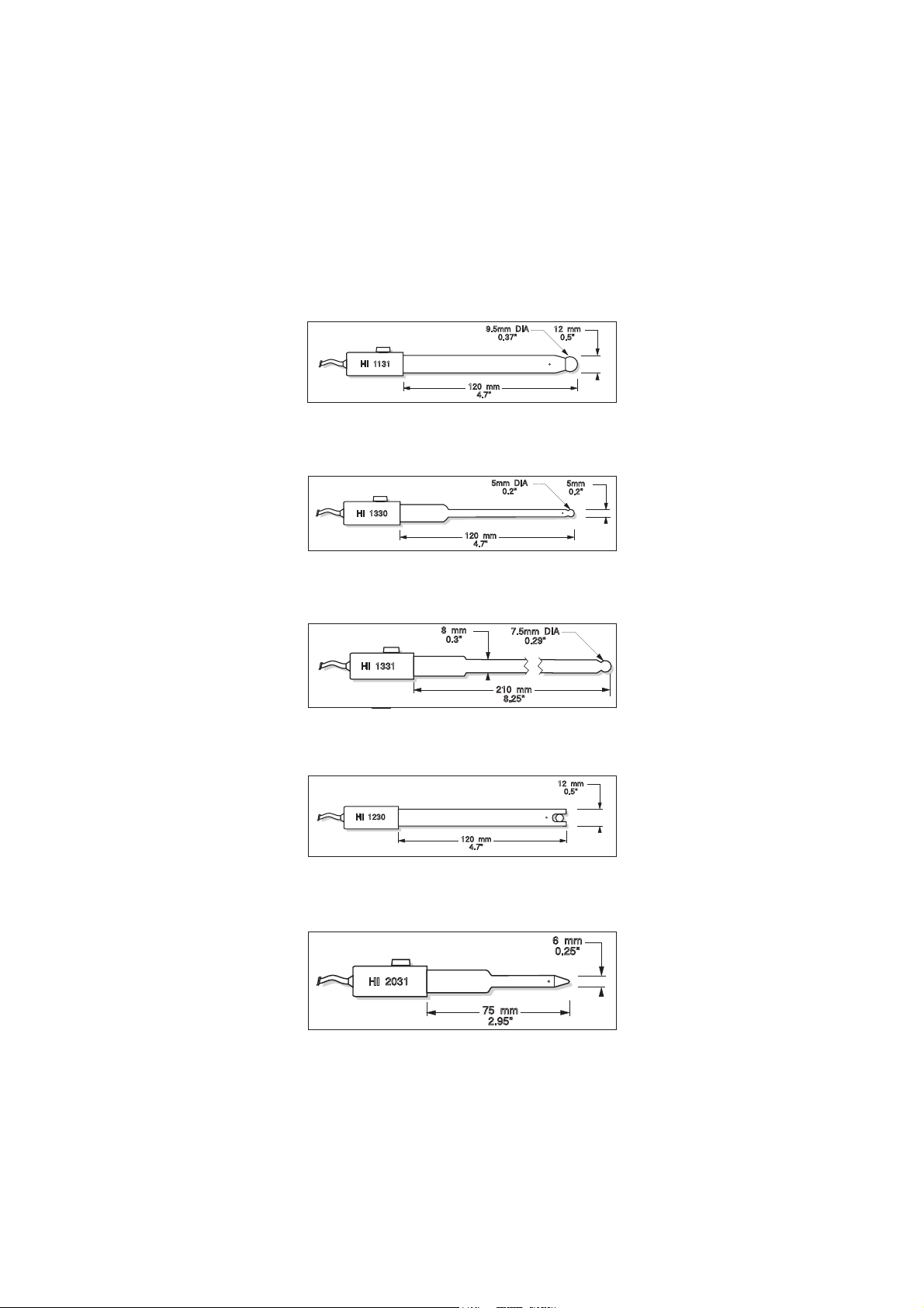
75 mm
2.95"
6 mm
0.25"
HI 2031
120 mm
4.7"
5mm
0.2"
5mm DIA
0.2"
"S" VERSION
HI 1330
HI 1131B
120 mm
4.7"
12 mm
0.5"
9.5mm DIA
0.37"
"S" VERSION
HI 1131
210 mm
8.25"
8 mm
0.3"
7.5mm DIA
0.29"
"S" VERSION
HI 1331
120 mm
4.7"
12 mm
0.5"
HI 1230
Glass-body, single junction, refillable, combination pH electrode.
Use: general purpose.
HI 1330B
Glass-body, semimicro, single junction, refillable, combination pH
electrode. Use: laboratory, vials.
HI 1331B
Glass-body, semimicro, single junction, refillable, combination pH
electrode. Use: flasks.
HI 1230B
Plastic-body (PES), double junction, gel-filled, combination pH
electrode. Use: general, field.
HI 2031B
Glass-body, semimicro, conic, refillable, combination pH electrode.
Use: semisolid products.
79
Page 80

120 mm
4.7"
12 mm
0.5"
9.5mm DIA
0.37"
FC 220
120 mm
4.7"
12 mm
0.5"
FC 210
75 mm
2.95"
6 mm
0.25"
FC 200
120 mm
4.7"
12 mm
0.5"
FC 100
120 mm
4.7"
12 mm
0.5"
"S" VERSION
HI 1332
HI 1332B
Plastic-body (PES), double junction, refillable, combination pH
electrode. Use: general purpose.
FC 100B
Plastic-body (PVDF), double junction, refillable, combination pH
electrode. Use: general purpose for food industry.
FC 200B
Plastic-body (PVDF), open junction, conic, Viscolene, non-refillable,
combination pH electrode. Use: meat & cheese.
FC 210B
Glass-body, double junction, conic, Viscolene, non-refillable, combination
pH electrode. Use: milk, yogurt.
FC 220B
Glass-body, triple-ceramic, single junction, refillable, combination pH
electrode. Use: food processing.
80
Page 81

120 mm
4.7"
12 mm
0.5"
HI 4430
"S" VERSION
120 mm
4.7"
12 mm
0.5"
HI 3230
"S" VERSION
150 mm
5.9"
12 mm
0.5"
"S" VERSION
HI 3131
110 mm
4.3"
12 mm
0.5"
HI 1413
110 mm
4.3"
12 mm
0.5"
FC 911
FC 911B
Plastic-body (PVDF), double junction, refillable with built-in amplifier,
combination pH electrode. Use: very high humidity.
HI 1413B
Glass-body, single junction, flat tip, Viscolene, non-refillable, combination
pH electrode. Use: surface measurement.
ORP ELECTRODES
HI 3131B
Glass-body, refillable, combination platinum ORP electrode.
Use: titration.
HI 3230B
Plastic-body (PES), gel-filled, combination platinum ORP electrode.
Use: general purpose.
HI 4430B
Plastic-body (PES), gel-filled, combination gold ORP electrode.
Use: general purpose.
Consult the Hanna General Catalog for a complete and wide selection of electrodes.
81
Page 82

EXTENSION CABLE FOR SCREW-TYPE ELECTRODES
(SCREW TO BNC ADAPTER)
HI 7855/1 Extension cable 1 m (3.3') long
HI 7855/3 Extension cable 3 m (9.9') long
OTHER ACCESSORIES
HI 740157 Plastic electrode refilling pipet (20 pcs)
HI 76404N Electrode holder
HI 7662-T Stainless steel Temperature probe with 1 m (3.3') screened cable
HI 8427 pH and ORP electrode simulator with 1 m (3.3') coaxial
cable ending in female BNC connectors
HI 931001 pH and ORP electrode simulator with LCD and 1 m (3.3')
coaxial cable ending in female BNC connectors
HI 76404N Electrode Holder
EC CALIBRATION SOLUTIONS
HI 70033C 84 µS/cm, 20 ml sachet, 25 pcs.
HI 70031C 1413 µS/cm, 20 ml sachet, 25 pcs.
HI 70039C 5000 µS/cm, 20 ml sachet, 25 pcs.
HI 70030C 12880 µS/cm, 20 ml sachet, 25 pcs.
HI 6033 84 µS/cm, 500 ml, bottle
HI 6031 1413 µS/cm, 500 ml, bottle
HI 7039L 5000 µS/cm, 500 ml, bottle
HI 7030L 12880 µS/cm, 500 ml, bottle
HI 7034L 80000 µS/cm, 500 ml, bottle
HI 7035L 11800 µS/cm, 500 ml, bottle
HI 7037L 100% NaCl, 500 ml, bottle
82
Page 83

RECOMMENDATIONS FOR USERS
Before using these products, make sure they are entirely suitable for the
environment in which they are used.
Operation of these instruments in residential areas could cause unacceptable interferences to radio and TV equipment, requiring the operator to
follow all necessary steps to correct interferences.
The glass bulb at the end of the pH electrode is sensitive to electrostatic
discharges. Avoid touching this glass bulb at all times.
During operation, ESD wrist straps should be worn to avoid possible
damage to the electrode by electrostatic discharges.
Any variation introduced by the user to the supplied equipment may
degrade the instruments’ EMC performance.
To avoid electrical shock, do not use these instruments when voltages at
the measurement surface exceed 24 VAC or 60 VDC.
To avoid damage or burns, do not perform any measurement in microwave ovens.
Hanna Instruments reserves the right to modify the design, construction
and appearance of its products without advance notice.
83
Page 84

Hanna Instruments Inc.
Highland Industrial Park
584 Park East Drive
Woonsocket, RI 02895 USA
Technical Support for Customers
Tel. (800) 426 6287
Fax (401) 765 7575
E-mail tech@hannainst.com
www.hannainst.com
Local Sales and Customer Service Office
Printed in EUROPE
(ROMANIA) MAN3512 07/10
84
 Loading...