

Page 1
Instruction Manual
HI 2550
Multiparameter
pH/ORP/°C
EC/TDS/NaCl
Bench Meter
www.hannainst.com
1
Page 2

Dear Customer,
Thank you for choosing a Hanna Instruments product.
Please read this instruction manual carefully before using this instrument.
This manual will provide you with the necessary information for correct
use of this instrument, as well as a precise idea of its versatility.
If you need additional technical information, do not hesitate to e-mail us
at tech@hannainst.com.
WARRANTYWARRANTY
WARRANTY
WARRANTYWARRANTY
HI 2550 is guaranteed for two years against defects in workmanship and
materials when used for their intended purpose and maintained according
to instructions. Electrodes and probes are guaranteed for six months. This
warranty is limited to repair or replacement free of charge.
Damage due to accidents, misuse, tampering or lack of prescribed
maintenance is not covered.
If service is required, contact the dealer from whom you purchased the
instrument. If under warranty, report the model number, date of
purchase, serial number and the nature of the problem. If the repair is
not covered by the warranty, you will be notified of the charges incurred.
If the instrument is to be returned to Hanna Instruments, first obtain
a Returned Goods Authorization number from the Technical Service
department and then send it with shipping costs prepaid. When shipping
any instrument, make sure it is properly packed for complete protection.
TABLE OF CONTENTSTABLE OF CONTENTS
TABLE OF CONTENTS
TABLE OF CONTENTSTABLE OF CONTENTS
WARRANTY .................................................................................................... 2
PRELIMINARY EXAMINATION ............................................................................ 3
GENERAL DESCRIPTION .................................................................................... 3
FUNCTIONAL DESCRIPTION .............................................................................. 4
SPECIFICATIONS ............................................................................................. 5
OPERATIONAL GUIDE ....................................................................................... 7
AUTO-RANGING ............................................................................................. 12
pH CALIBRATION ............................................................................................ 13
pH BUFFER TEMPERATURE DEPENDENCE .........................................................18
RELATIVE mV CALIBRATION .............................................................................. 19
ECS/TDS CALIBRATION .................................................................................... 19
CONDUCTIVITY VERSUS TEMPERATURE CHART ................................................... 21
NaCl CALIBRATION .........................................................................................22
GOOD LABORATORY PRACTICE (GLP) ................................................................. 23
LOGGING FUNCTION ....................................................................................... 28
SETUP .......................................................................................................... 36
TEMPERATURE CALIBRATION (FOR TECHNICAL PERSONNEL ONLY) ....................... 42
mV CALIBRATION (FOR TECHNICAL PERSONNEL ONLY) .......................................44
PC INTERFACE ............................................................................................... 45
ELECTRODE CONDITIONING & MAINTENANCE .................................................... 51
TROUBLESHOOTING GUIDE .............................................................................. 54
TEMPERATURE CORRELATION FOR pH SENSITIVE GLASS ..................................... 55
ACCESSORIES ............................................................................................... 56
2
Page 3

PRELIMINARY EXAMINATIONPRELIMINARY EXAMINATION
PRELIMINARY EXAMINATION
PRELIMINARY EXAMINATIONPRELIMINARY EXAMINATION
Remove the instrument from the packing material and examine it carefully
to make sure that no damage has occurred during shipping. If there is any
damage, notify your Dealer or the nearest Hanna Customer Service Center.
Each instrument is supplied with:
• HI 1131B Glass-body Combination pH Electrode with 1 m (3.3')
Cable
• HI 76310 Conductivity / TDS probe
• HI 7662 Temperature Probe
• HI 76404N Electrode Holder
• pH 4.01 & 7.01 Buffer Solutions (20 mL each)
• HI 7071 Electrolyte Solution
• 12VDC Power Adapter
• Instruction Manual
Note: Save all packing material until you are sure that the instrument
functions correctly. All defective items must be returned in the
original packing with the supplied accessories.
GENERAL DESCRIPTIONGENERAL DESCRIPTION
GENERAL DESCRIPTION
GENERAL DESCRIPTIONGENERAL DESCRIPTION
The HI 2550 is a microprocessor based pH, ORP, Conductivity (EC), TDS,
NaCl, and Temperature Bench Meter. Relative mV feature is also
provided.
pH measurements are compensated for temperature effect manually or
automatically with the HI 7662 temperature probe.
Up to a five-point pH calibration can be performed using seven standard
buffers and two custom buffers.
A calibration due alarm can be set to alert the user that too much time
has elapsed since the last pH calibration.
Conductivity and TDS features auto-ranging, which automatically selects
the scale with the highest resolution. Conductivity measurements are
compensated for temperature manually or automatically with a
temperature sensor located inside the probe. The temperature coefficient
is user selectable. Temperature compensation can be disabled to measure
actual conductivity.
The GLP feature provides data consistency.
Data can be stored in the meters memory for later retrieval. The meters
memory can hold 200 manually logged points and 500 lot logging
points.
An USB connection ensures communication with a PC.
3
Page 4

FUNCTIONAL DESCRIPTIONFUNCTIONAL DESCRIPTION
FUNCTIONAL DESCRIPTION
FUNCTIONAL DESCRIPTIONFUNCTIONAL DESCRIPTION
Front Panel
Rear Panel
1) Liquid Crystal Display (LCD).
2) CAL key, to enter and exit calibration mode.
RCL key (alternate function), to enter and exit memory recall.
3) CFM/GLP key, to confirm calibration selection, different setup values
or to display Good Laboratory Practice information.
4)
ºC key, to manually increase temperature value or other parameters.
TC key (alternate function), to view temperature coefficient value.
ºC key, to manually decrease temperature value or other parameters.
5)
ATC key (alternate function), to select EC temperature compensation mode.
6) SETUP key, to enter/exit SETUP mode.
LOCK key (alternate function), to freeze current EC range on the LCD.
7) RANGE key, to select measurement range (pH, mV, EC), switch to
focused data in SETUP or toggle between buffer value and temperature
during calibration.
MODE key (alternate function) to select mV or Rel mV on mV range
or EC, TDS, NaCl on EC range.
8) LOG/CLR key, to store a value into memory, to clear pH calibration,
or to select to delete log records or lots.
9) ALT key, to select alternate function.
10) ON/OFF switch.
11) Power supply socket.
12) USB connector.
13) EC electrode connector.
14) BNC electrode connector.
15) Temperature probe socket.
16) Electrode reference socket.
4
Page 5
SPECIFICATIONSSPECIFICATIONS
SPECIFICATIONS
SPECIFICATIONSSPECIFICATIONS
Hp0.61ot0.2–
Hp00.61ot00.2–
Hp000.61ot000.2–
)PRO&ESI(Vm9.999±
)PRO&ESI(Vm0002±
mc/Sμ99.92ot00.0
9.992ot0.03
mc/Sμ
mc/Sμ9992ot003
mc/Sm99.92ot00.3
cnu
μ
μ
μ
Cº1.0
(gnidaerfo%1±±1rompp30.0
mc/Sm0.002ot0.03
ytivitcudnoc
mpp99.41ot00.0
mpp9.941ot0.51
mpp9941ot051
l/g99.41ot05.1
l/g0.001ot0.51
)*(
)rotcaf08.0htiw(
lCaN%0.004ot0.0
Hp1.0
Hp10.0
Hp100.0
)Vm0.0001±(Vm
)Vm0002±(Vm1
mc/S
mc/S
mc/S
mc/Sm10.0
mc/Sm1.0
mpp10.0
mpp1.0
mpp1
l/g10.0
l/g1.0
lCaN%1.0
Hp10.0±
Hp200.0±
)Vm9
.999±(Vm2.0±
)Vm0002±(Vm1±
μ
50.0±(gnidaer%1±
retaergrevehcihw,tigid)
)retaergrevehcihw,tigid
gnidaerfo%1±
EGNAR
l/g0.004otpudetasnepmo
1.0
10.0
1.0
NOITULOSER
YCARUCCA
F°86/C°02@
(*)
Uncompensated conductivity (or TDS) is the conductivity (or TDS) value without
1
ulcxe(Cº4.0±
temperature compensation.
)*(
detasnepmocnumc/Sm0.005otpu
SDT
)egnarCE,Hp(Cº0.021ot0.02–
1romc/S
)rorreeborpgnid
5
Page 6
egnartesffoVmleRVm0002±
noitarbilaCHp
noitarbilaCCE
noitarbilaClCaNhtiwtniop1 L7307IH )lanoitpo(reffub
erutarepmeT
noitasnepmoc
ytivitcudnoC
tneiciffeocerutarepmet
rotcafSDT
edortcelEHp B1311IH
eborPCE 01367IH
eborperutarepmeT 2667IH
ecnadepmitupnI
)tupniCN
B(
erutaefdnamednogoLsdrocer002
erutaeflavretnIgoL
noitacinummocCPBSUdetalosiotpO
ylppusrewoPretpadaCDV21
snoisnemiD)”3.4x7.8x2.9(mm901x222x532
thgieW
tnemnorivnE
ytnarraWsraey2
,noitarbilactniop5ro4,3,2,1
elbaliavasreffubdradnats7
,)54.21,10.01,81.9,10.7,68.6,10.4,86.1(
sreffubmotsuc2dna
;noitarbilacepolstniop1
:elbaliavasreffub6
3141,0.48
μ
mc/S
mc/Sm8.111,0.08,88.21,00.5
:tesffotniop1
00.0
μ
mc/S
:morfcitamotuArolaunaM
)EGNA
RHp(Cº0.021ot0.02–
)EGNARCE(Cº0.021ot0.02–
otegnarytivitcudnocnodelbasidebnac(
ytivitcudnoclautcaerusaem
Cº/%00.6ot00.0
)ylnoSDTdnaCErof(
Cº/%09.1sieulavtluafed
08.0o
t04.0
)05.0sieulavtluafed(
21
smho
01
sdrocer005
,)”bAtS”(gniggolytilibatS
ces03,01,5
nim081,
021,06,03,51,01,5,2,1
;)bl9.2(gK3.1
)bl6.4(gK1.2redlohhtiwtik
)Fº221–23(Cº05–0
gnisnednoc-nonHR%59.xam
6
Page 7
OPERATIONAL GUIDEOPERATIONAL GUIDE
OPERATIONAL GUIDE
OPERATIONAL GUIDEOPERATIONAL GUIDE
POWER CONNECTIONPOWER CONNECTION
POWER CONNECTION
POWER CONNECTIONPOWER CONNECTION
Plug the 12 VDC adapter into the power supply socket.
Notes: • This instrument uses non volatile memory to retain the calibration
parameters and all other settings, even when unplugged.
• Make sure a fuse protects the main line.
ELECTRODE AND PROBE CONNECTIONSELECTRODE AND PROBE CONNECTIONS
ELECTRODE AND PROBE CONNECTIONS
ELECTRODE AND PROBE CONNECTIONSELECTRODE AND PROBE CONNECTIONS
For pH or ORP measurements connect an electrode with internal reference
to the BNC connector on the back of the instrument.
For electrodes with a separate reference connect the electrode’s BNC to the
BNC connector and the reference electrode plug to the reference socket.
For temperature measurements and automatic temperature compensation
connect the temperature probe to the appropriate socket.
For EC/TDS measurements connect the probe to the 7-pin connector.
Make sure the probe sleeve is properly inserted.
INSTRUMENT STINSTRUMENT ST
INSTRUMENT ST
INSTRUMENT STINSTRUMENT ST
ARTART
ART
ARTART
-UP-UP
-UP
-UP-UP
• Turn the instrument on by pressing the ON/OFF switch located on
the rear panel.
• All LCD tags are displayed and a beep is sounded while the
instruments perform a self test.
• The instrument will display “LoAd” message and “ ” blinking until
initialization is complete.
Notes: • The instrument starts in the same range and mode as it was
at power off.
• The ALT&MODE keys change the measuring modes:
- mV or Rel mV
- EC or TDS or NaCl
• The RANGE key toggles between measurement ranges:
- pH, mV or Rel mV, EC or TDS or NaCl.
pH MEASUREMENTS
Make sure the instrument has been calibrated before
taking pH measurements.
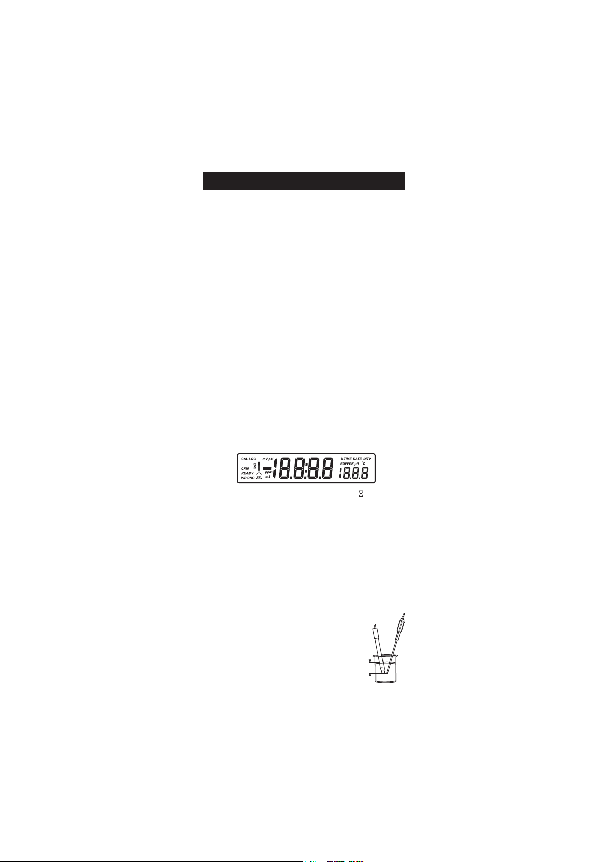
• Submerse the electrode tip and the temperature
probe approximately 3 cm (1¼”) into the sample
3 cm
(1¼")
to be tested and stir gently. Allow time for the
electrode to stabilize.
7
Page 8
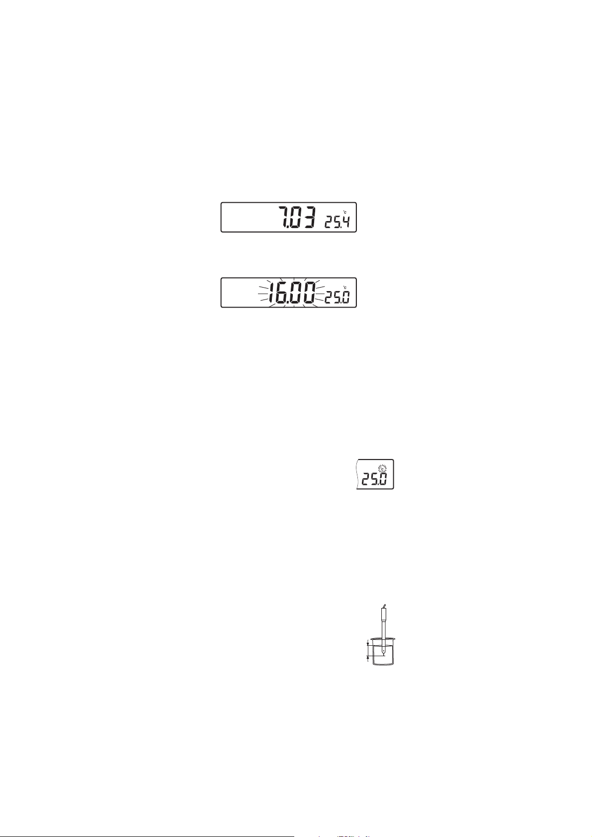
• The pH is displayed on the primary LCD and the temperature on the
secondary LCD.
pH
• If the reading is out of range, the closest full-scale value will be
displayed blinking on the primary LCD.
pH
If measurements are taken successively in different samples, it is recommended
to rinse the electrode thoroughly with deionized water or tap water and
then with some of the next sample to prevent cross-contamination.
The pH reading is affected by temperature. In order to measure the pH
accurately, the temperature effect must be compensated for. To use the
Automatic Temperature Compensation feature, connect and submerse
the HI 7662 temperature probe into the sample as close as possible to
the electrode and wait for a few seconds.
If the temperature of the sample is known, manual temperature
compensation can be used by disconnecting the temperature probe.
The display will show the last temperature reading with
the “ºC” tag blinking.
The temperature can now be adjusted with the ARROW
keys (from –20.0 ºC to 120.0 ºC).
mV/ORP MEASUREMENTSmV/ORP MEASUREMENTS
mV/ORP MEASUREMENTS
mV/ORP MEASUREMENTSmV/ORP MEASUREMENTS
An optional ORP electrode must be used to perform ORP measurements
(see Accessories).
Oxidation-Reduction Potential (REDOX) measurements provide the
quantification of the oxidizing or reducing power of the tested sample.
The surface of the ORP electrode must be clean and smooth in order to
obtain an accurate measurement.
• Press RANGE to enter mV range.
• Submerse the tip of the ORP electrode (3 cm/1¼”)
into the sample to be tested and allow a few
seconds for the reading to stabilize.
3 cm
(1¼")
8
Page 9
• The instrument displays the mV reading on the primary LCD and the
temperature on the secondary LCD line.
mV
• If the reading is out of range, the closest full-scale value will be
displayed blinking on the primary LCD.
mV
RELATIVE mV MEASUREMENTSRELATIVE mV MEASUREMENTS
RELATIVE mV MEASUREMENTS
RELATIVE mV MEASUREMENTSRELATIVE mV MEASUREMENTS
• Press the ALT&MODE keys simultaneously while in mV range. The
“rEL” and “mV” tags are displayed for about one second. After one
second the temperature will be displayed on the secondary LCD and
the “mV” tag will blink.
mV
The reading displayed by the instrument is equal to the difference
between the current mV input value and the relative mV offset established
in the relative mV calibration.
CONDUCTIVITY MEASUREMENTSCONDUCTIVITY MEASUREMENTS
CONDUCTIVITY MEASUREMENTS
CONDUCTIVITY MEASUREMENTSCONDUCTIVITY MEASUREMENTS
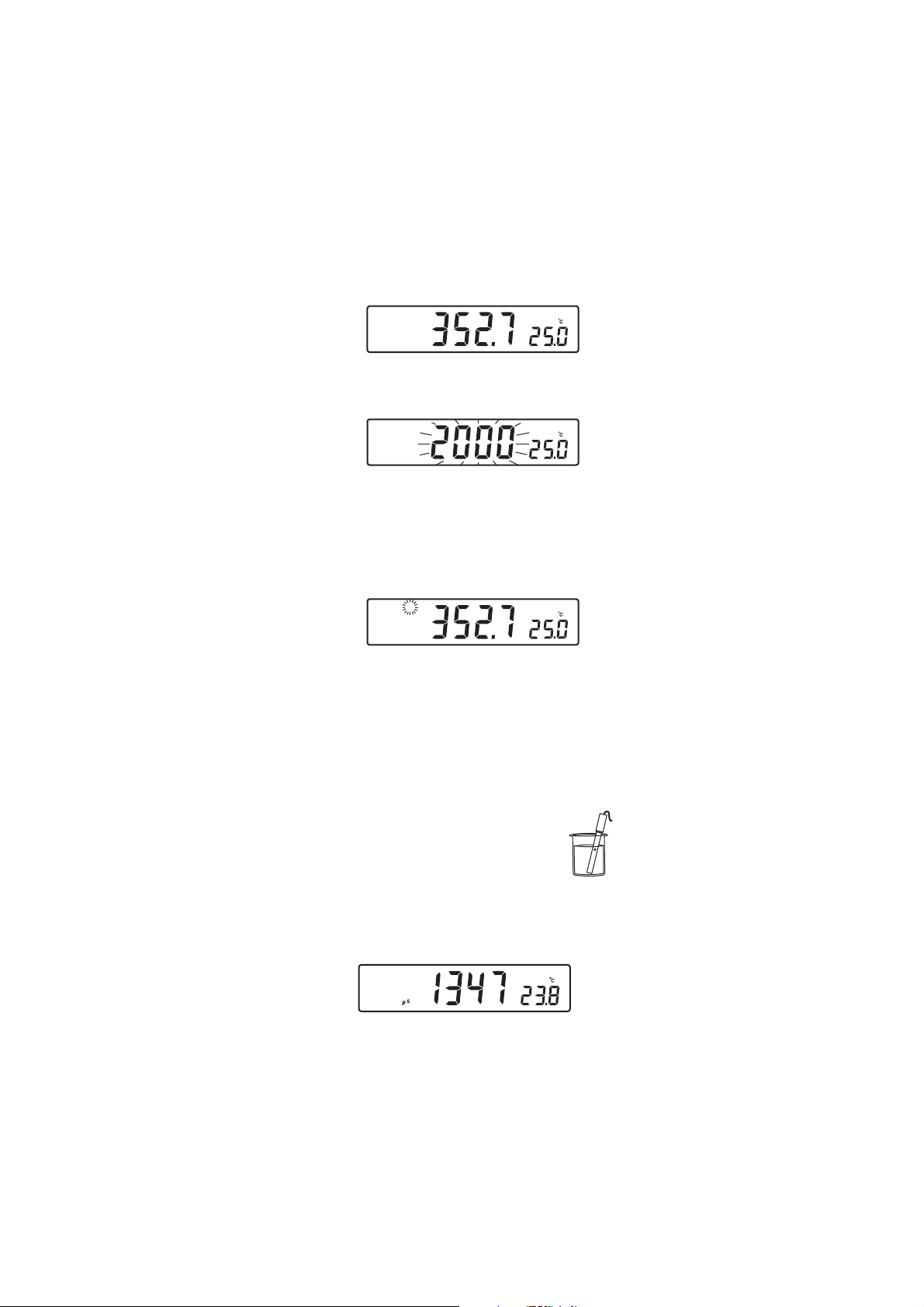
Connect the conductivity probe to the instrument.
• Press the RANGE key to enter conductivity measurement range (EC).
• Submerse the probe into the solution to be tested. The
sleeve holes must be completely submersed. Tap the
probe repeatedly to remove any air bubbles that may
be trapped inside the sleeve.
• The conductivity value will be displayed on the primary
LCD and the temperature on the secondary LCD.
• If the reading is out of range, the full-scale value (200.0 for MTC/ATC
mode or 500.0 for actual conductivity) will be displayed blinking.
9
Page 10
• If LOCK key was pressed and the reading goes out of range, the
full-scale value of the frozen range will be displayed blinking.
The conductivity reading is affected by temperature.
Three options for temperature compensation are available in conductivity
measurement mode.
Automatic (ATC): The conductivity probe has a built-in temperature
sensor; the temperature value is used to automatically compensate the
EC/TDS reading.
Manual (MTC): The temperature value, shown on the secondary LCD,
can be manually set with the ARROW keys. The “ºC” tag blinks when
this option is active. This value will be used to compensate the EC/TDS
reading.
No Compensation (notc): The temperature value is displayed, but not
taken into account. When this option is selected the “ºC” tag will blink
with slower frequency. The reading displayed on the primary LCD is the
uncompensated EC or TDS value.
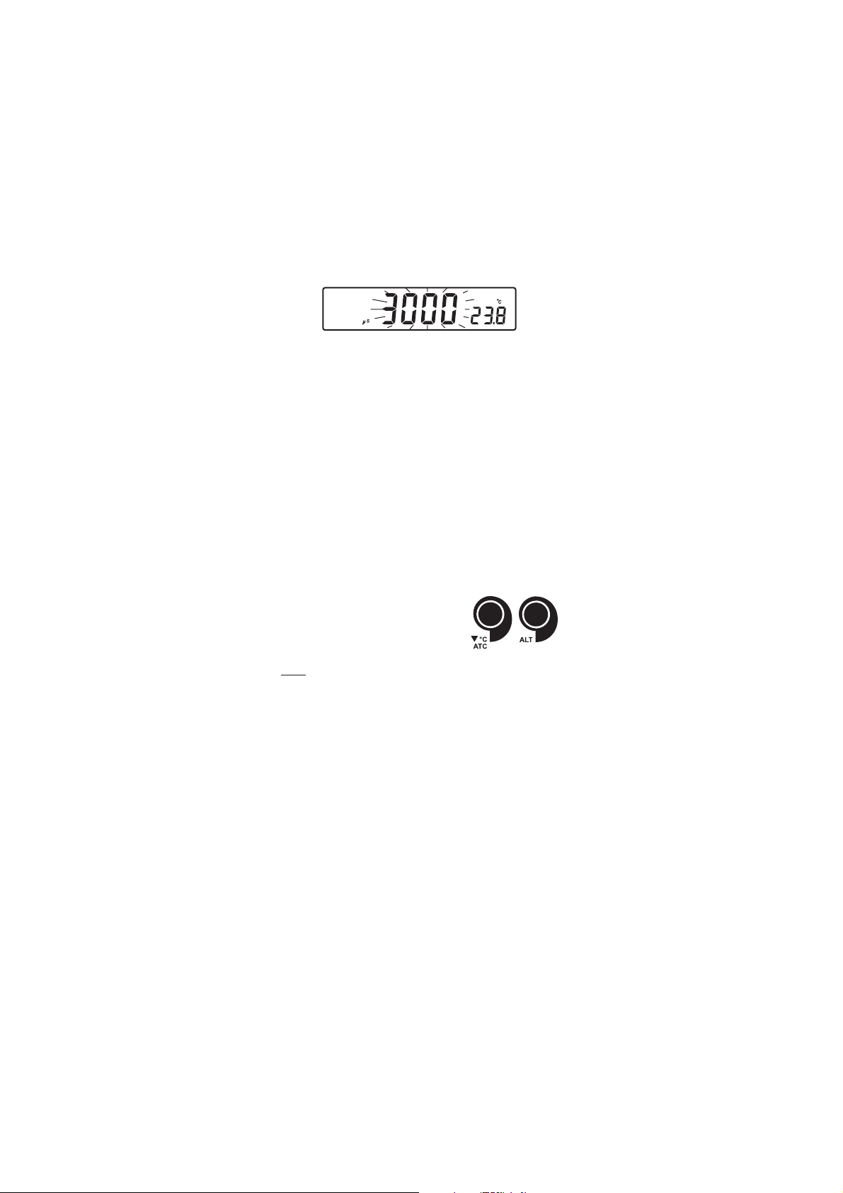
To select the desired option, press the
ALT&ATC keys until the option is displayed
on the LCD.
Notes:• The default compensation mode is ATC.
• If no temperature probe is detected, ATC mode can not be
selected and the instrument displays “----” on the secondary LCD.
If temperature compensation is selected, measurements are compensated
using the temperature coefficient (default value 1.90 %/ºC). To change
the temperature coefficient, enter the setup mode and select “tc” (see
SETUP for details, page 36). The current temperature coefficient can be
quickly viewed by pressing the ALT&TC keys. The value is briefly
displayed on the secondary LCD.
• If the temperature reading exceeds the limits of the meter (–20.0 ºC
to 120.0 ºC), the “ºC” tag will blink and the closest full scale value
will be displayed.
10
Page 11
TDS MEASUREMENTSTDS MEASUREMENTS
TDS MEASUREMENTS
TDS MEASUREMENTSTDS MEASUREMENTS
Press the ALT&MODE keys while in EC range. The instrument will switch
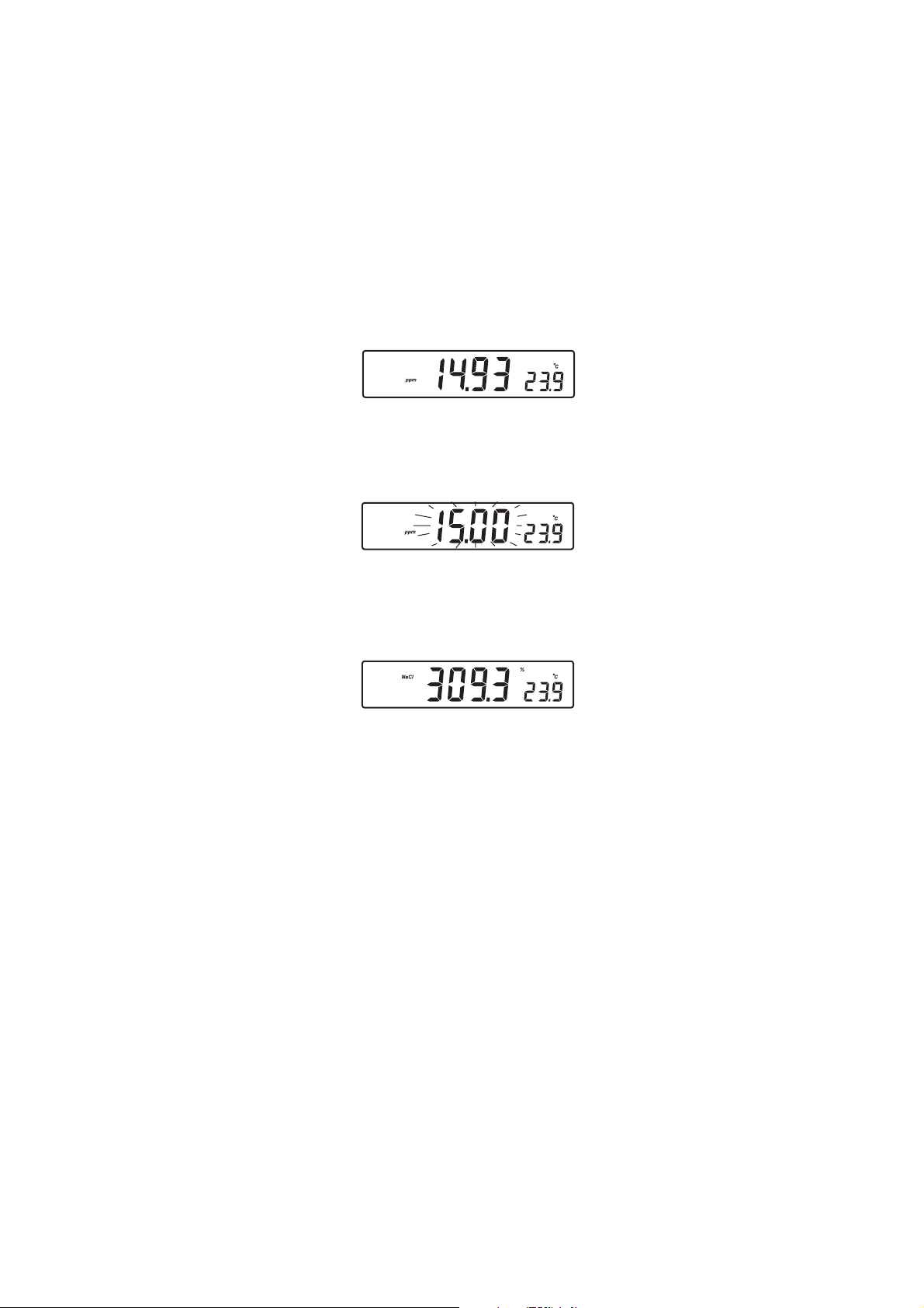
to TDS measuring range. The TDS reading will be displayed on the
primary LCD and the temperature reading on the secondary LCD.
• If the reading is out of range, the full-scale value (100.0 for MTC/ATC
mode or 400.0 for uncompensated TDS) will be displayed blinking.
• If LOCK was pressed and the reading goes out of range, the full-scale
value of the frozen range will be displayed blinking.
NaCl MEASUREMENTSNaCl MEASUREMENTS
NaCl MEASUREMENTS
NaCl MEASUREMENTSNaCl MEASUREMENTS
Press the ALT&MODE keys while in EC range until NaCl is displayed on
the LCD. The instrument will display the NaCl reading on the primary LCD
and the temperature reading on the secondary LCD line.
• If the reading is out of range, the full-scale value (400.0%) will be
displayed blinking.
TEMPERATURE MEASUREMENTSTEMPERATURE MEASUREMENTS
TEMPERATURE MEASUREMENTS
TEMPERATURE MEASUREMENTSTEMPERATURE MEASUREMENTS
In pH and ORP mode, connect the HI 7662 temperature probe to the
appropriate socket.
Submerse the temperature
on the secondary LCD to stabilize.
In EC/TDS/NaCl range, the HI 76310 probe has a built-in temperature
sensor.
probe
into the sample and allow the reading
11
Page 12

AUTO-RANGINGAUTO-RANGING
AUTO-RANGING
AUTO-RANGINGAUTO-RANGING
The EC and TDS scales are auto-ranging. The meter automatically sets
the scale with the highest possible resolution.
By pressing ALT&LOCK, the auto-ranging feature is disabled and the
current range is frozen on the LCD. The “Auto” “Off” (auto-ranging
disabled) tags will be displayed on the LCD for a few seconds. To restore
the auto-ranging option, press ALT&LOCK again. The “Auto” “On”
(auto-ranging enabled) tags will be displayed on the LCD for a few
seconds.
Note: Auto-ranging is automatically restored if the range is changed, if
the setup or calibration modes are entered and if the meter is
turned off and back on again.
12
Page 13

pp
H CALIBRATIONH CALIBRATION
p
H CALIBRATION
pp
H CALIBRATIONH CALIBRATION
Calibrate the instrument frequently, especially if high accuracy is required.
The instrument should be recalibrated:
• Whenever the pH electrode is replaced.
• At least once a day.
• After testing aggressive chemicals.
• If “CAL” “INTV” tags are blinking during measurement.
Every time you calibrate the instrument use fresh buffers and perform an
electrode Cleaning Procedure (see page 53).
PREPARATIONPREPARATION
PREPARATION
PREPARATIONPREPARATION
Pour small quantities of the buffer solutions into clean beakers. If possible,
use plastic or glass beakers to minimize any EMC interferences.
For accurate calibration and to minimize cross-contamination, use two
beakers for each buffer solution. One for rinsing the electrode and one for
calibration.
If you are measuring in the acidic range, use pH 7.01 or 6.86 as first buffer
and pH 4.01 as second buffer. If you are measuring in the alkaline range,
use pH 7.01 or 6.86 as first buffer and pH 10.01 or 9.18 as second buffer.
PROCEDUREPROCEDURE
PROCEDURE
PROCEDUREPROCEDURE
Calibration can be performed at up to five-points.
For accurate measurements, a three-point calibration is recommended.
The calibration buffer can be selected from the calibration buffer list that
includes the custom buffers and the memorized standard buffers:
• pH 1.68, 4.01, 6.86, 7.01, 9.18, 10.01 and 12.45
The custom buffers allow the user to calibrate in a buffer solution different
from a standard one. Up to two custom buffers can be set in SETUP menu
(see page 36). Each custom buffer value can be changed in a ±1.0 pH
window around the set value, during calibration, when it is selected; the
“BUFFER pH” tag will blink.
The instruments will automatically skip the buffer used during calibration
and the buffers which are in a ±0.2 pH window, around one of the
calibrated buffers.
All new calibrations will override existing stored calibration data in a
±0.2 pH window. The slopes adjacent to the new points will be
reevaluated.
13
Page 14
FIVEFIVE
--
POINTPOINT
FIVE
FIVEFIVE
-
--
CALIBRATION CALIBRATION
POINT
CALIBRATION
POINTPOINT
CALIBRATION CALIBRATION
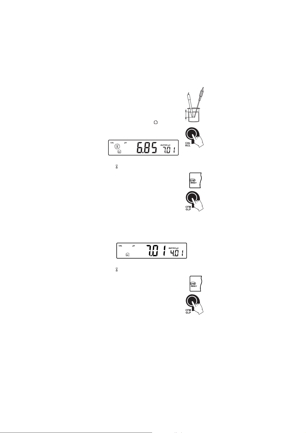
• Submerse the pH electrode and the temperature
probe approximately 3 cm (1¼”) into a buffer
solution and stir gently. The temperature probe
should be close to the pH electrode.
• Press CAL. The “CAL” and “
BUF
” tags will
3 cm
(1¼")
appear and the “7.01” buffer will be displayed
on the secondary LCD.
• If necessary, press the ARROW keys to select a different buffer value.
• The “ ” tag will blink on the LCD until the reading is stable.
• When the reading is stable and close to the selected
buffer, the “READY” tag will be displayed and the
“CFM” tag will blink.
• Press CFM to confirm calibration.
• The calibrated value is then displayed on the primary
LCD and the second expected buffer value on the
secondary LCD.
• After the first calibration point is confirmed, submerse the pH
electrode and the temperature probe approximately 3 cm (1¼”)
into the second buffer solution and stir gently. The temperature
probe should be close to the pH electrode.
• If necessary, press the ARROW keys to select a different buffer value.
• The “ ” tag will blink on the LCD until the reading is stable.
• When the reading is stable and close to the selected
buffer, the “READY” tag will be displayed and the
“CFM” tag will blink.
• Press CFM to confirm calibration.
• The calibrated value is then displayed on the primary
LCD and the third expected buffer value on the
secondary LCD.
• After the second calibration point is confirmed, submerse the pH
electrode and the temperature probe approximately 3 cm (1¼”) into
the third buffer solution and stir gently. The temperature probe
should be close to the pH electrode.
14
Page 15
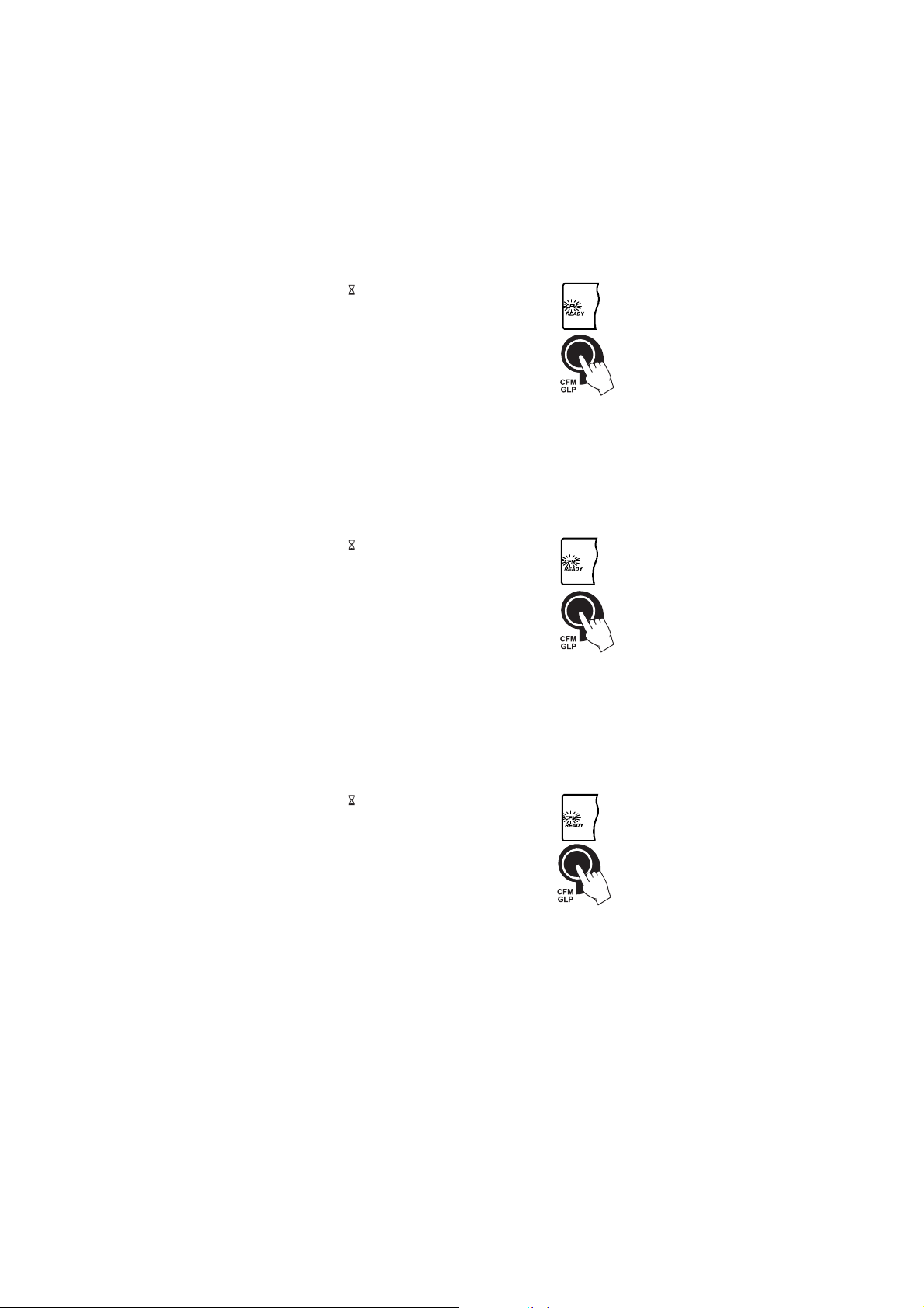
• If necessary, press the ARROW keys to select a different buffer value.
• The “ ” tag will blink on the LCD until the reading is
stable.
• When the reading is stable and close to the selected
buffer, the “READY” tag will be displayed and the
“CFM” tag will blink.
• Press CFM to confirm calibration.
• The calibrated value is then displayed on the primary LCD and the
fourth expected buffer value on the secondary LCD.
• After the third calibration point is confirmed, submerse the pH electrode
and the temperature probe approximately 3 cm (1¼”) into the fourth
buffer solution and stir gently. The temperature probe should be close
to the pH electrode.
• If necessary, press the ARROW keys to select a different buffer value.
• The “ ” tag will blink on the LCD until the reading is
stable.
• When the reading is stable and close to the selected
buffer, the “READY” tag will be displayed and the
“CFM” tag will blink.
• Press CFM to confirm calibration.
• The calibrated value is then displayed on the primary LCD and the
fifth expected buffer value on the secondary LCD.
• After the fourth calibration point is confirmed, submerse the pH
electrode and the temperature probe approximately 3 cm (1¼”) into
the fifth buffer solution and stir gently. The temperature probe
should be close to the pH electrode.
• If necessary, press the ARROW keys to select a different buffer value.
• The “ ” tag will blink on the LCD until the reading is
stable.
• When the reading is stable and close to the selected
buffer, the “READY” tag will be displayed and the
“CFM” tag will blink.
• Press CFM to confirm the fifth calibration point.
• The instrument stores the calibration value and returns to normal
measurement mode.
FOUR, THREE OR TWO-POINT CALIBRATIONFOUR, THREE OR TWO-POINT CALIBRATION
FOUR, THREE OR TWO-POINT CALIBRATION
FOUR, THREE OR TWO-POINT CALIBRATIONFOUR, THREE OR TWO-POINT CALIBRATION
• Proceed as described in “FIVE-POINT CALIBRATION” section.
• Press CAL after the fourth, third or second calibration point was
confirmed. The instruments will memorize the calibration data and
return to measurement mode.
15
Page 16

ONE-POINT CALIBRATIONONE-POINT CALIBRATION
ONE-POINT CALIBRATION
ONE-POINT CALIBRATIONONE-POINT CALIBRATION
Two SETUP selectable options are available: “Pnt” and “OFFS”.
If the “Pnt” option is selected, the new calibration point overrides an
existing one. The adjacent slopes will be reevaluated.
If the “OFFS” option is selected, an electrode offset correction is performed.
The adjacent slopes will remain unchanged.
• Proceed as described in “FOUR, THREE or TWO-POINT CALIBRATION”
section.
• Press CAL after the first calibration point was confirmed. The
instruments will memorize the one-point calibration data and
return to measurement mode.
Notes: • If the value measured by the instrument is not close to the
selected buffer, “WRONG” “ ” and “WRONG” “ ” tags
will blink alternately. Check if the correct buffer has been
used, or clean the electrode by following the Cleaning
Procedure (see page 53). If necessary, change the buffer or
the electrode.
• When a custom buffer is displayed, the “BUFFER pH” tag
blinks. To change the custom buffer value in accordance with
the buffer temperature proceed as described in “WORKING
WITH CUSTOM BUFFERS” (see page 17).
• If the buffer temperature or the manual temperature
exceeds the temperature limits of the buffer, “WRONG” tag
and temperature reading will blink.
• If “WRONG”, “BUFFER pH” tags and “OLD” message are
displayed blinking on the secondary LCD line, an inconsistency
between new and previous (old) calibration is detected.
Clear calibration parameters and proceed with calibration
from the current calibration point. The instrument will keep
all confirmed values during current calibration.
• To clear calibration parameters for all uncalibrated buffers
starting with current buffer, press CLR. The calibration will
continue from the current point. If this procedure is
performed while calibrating in the first calibration point,
the instrument returns to measurement mode.
• Press RANGE to toggle between pH buffer,
calibration buffer number and temperature
reading.
16
Page 17
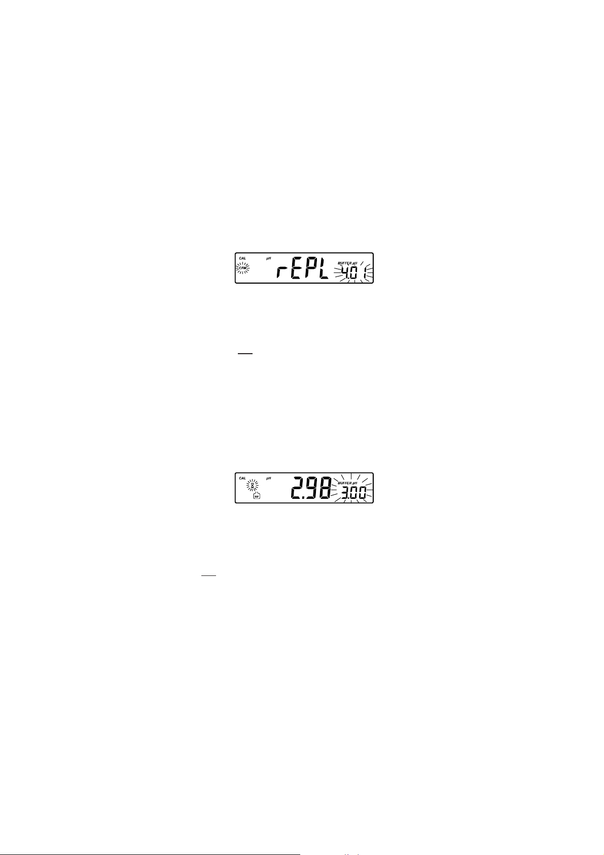
• Each time a buffer is confirmed, the new calibration data
replaces the old calibration data for the corresponding buffer.
If current buffer has no previous data stored and the calibration is not full (five buffers), the current buffer is added
to the existing calibration. If the existing calibration is full,
the instrument asks which buffer to replace.
Press the ARROW keys to select another buffer to be
replaced.
Press CFM to confirm the buffer that will be replaced.
Press CAL to leave calibration without replacing.
Note: If the replaced buffer is outside the ±0.2 pH window,
around each of the calibrated buffers, it is possible to
select this buffer for next calibration during current
calibration.
WORKING WITH CUSTOM BUFFERSWORKING WITH CUSTOM BUFFERS
WORKING WITH CUSTOM BUFFERS
WORKING WITH CUSTOM BUFFERSWORKING WITH CUSTOM BUFFERS
If a custom buffer was set in SETUP menu, it can be selected during
calibration by pressing the ARROW keys. The “BUFFER pH” tag will
blink.
Press SETUP if you want to adjust the buffer value. The buffer value will
start blinking.
Use the ARROW keys to change the buffer value.
After 5 seconds, the buffer value is updated. Press SETUP if you want to
change it again.
Note: Custom buffer value can be adjusted in a ±1.00 pH window,
around the set value.
17
Page 18
pp
H BUFFER TEMPERATUREH BUFFER TEMPERATURE
p
H BUFFER TEMPERATURE
pp
H BUFFER TEMPERATUREH BUFFER TEMPERATURE
DEPENDENCEDEPENDENCE
DEPENDENCE
DEPENDENCEDEPENDENCE
The temperature has an effect on pH. The calibration buffer solutions are
affected by temperature changes to a lesser degree than normal solutions.
During calibration the instrument will automatically calibrate to the pH
value corresponding to the measured or set temperature.
PMETSREFFUBHp
CºFº86.110.468.610.781.910.0154.21
023 76.110.489.631.764.923.0183.31
514 76.100.459.601.793.942.0181.31
0105 76.100.429
5195 76.100.409.650.772.921.0108.21
0286 86.100.488.630.722.960.0126.21
5277 86.110.468.610.781.910.0154.21
0368 8
5359 96.130.448.699.611.929.931.21
04401 96.140.448.689.670.988.989.11
54311 07.150.438.689.640.958.938.1
05221 17.160.438.689.610.928.907.11
55131 27.180.448.689.699.897.975.11
06041 27.190.448.689.679.877.944.11
56941 37.111.448.699.659.
07851 47.121.458.699.639.857.912.11
57761 67.141.468.600.719.847.901.11
08671 77.161.478.610.798.847.900.11
58581 87.171.478
6.120.458.600.741.969.992.21
.670.733.981.0199.21
867.923.11
.620.778.847.919.01
1
09491 97.191.488.630.758.857.928.01
59302 18.102.498.640.738.867.937.01
During calibration the instrument will display the pH buffer value at 25 ºC.
18
Page 19
RELATIVE RELATIVE
RELATIVE
RELATIVE RELATIVE
• Press CAL when the instrument is in RELATIVE mV measurement
mode. The “mV” and “ ” tags will be displayed. Absolute mV is
displayed on the primary LCD and “AbS” message is displayed on the
secondary LCD.
• When the absolute reading is stable and in measurement range, the
instrument asks for confirmation.
• If the reading is out of range, “WRONG” tag will be displayed.
• Press CFM to confirm the absolute value. The instrument will display
0.0 mV on the primary LCD and “rEL” message on the secondary
LCD. In this moment the relative mV offset is equal to absolute mV
reading.
• Use the ARROW keys if you want to change the displayed relative
mV value.
• Press CFM to confirm the relative mV value. The instrument returns
to measurement mode.
Note: The relative mV value can be changed only inside the relative mV
offset window (± 2000 mV).
EC/TDS CALIBRATIONEC/TDS CALIBRATION
EC/TDS CALIBRATION
EC/TDS CALIBRATIONEC/TDS CALIBRATION
Selectable calibration points for conductivity are 0.00 μS for offset and
84.0 μS, 1413 μS, 5.00 mS, 12.88 mS, 80.0 mS, 111.8 mS for slope.
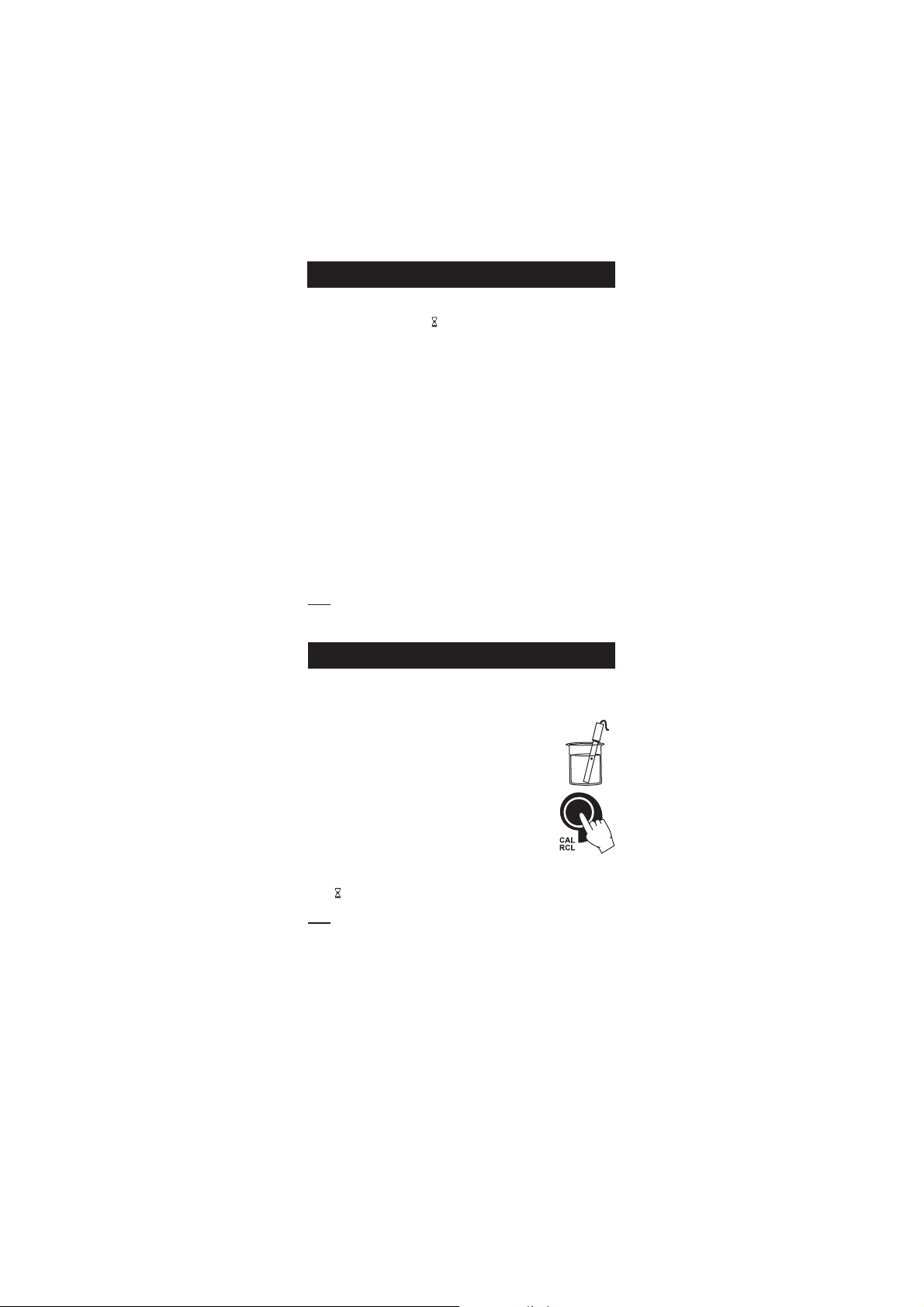
Rinse the probe with calibration solution or deionized
water. Submerse the probe into the solution. The sleeve
holes must be completely submersed. Tap the probe
repeatedly to remove any air bubbles that may be trapped
inside the sleeve.
To enter EC calibration, select the EC range and press
CAL.
The “BUF” and “CAL” tags are displayed. The primary
LCD will display the EC reading. The secondary LCD will display the value.
The “ ” and “~” tags will blink.
Note: The TDS reading is automatically derived from the EC reading and
no specific calibration for TDS is needed. Pressing CAL when TDS
range is selected has no effect.
For zero calibration, just leave the dry probe in the air. This calibration
is performed in order to correct the reading at 0.00 μS. The slope is
evaluated when the calibration is performed at any other point.
mm
V CALIBRATIONV CALIBRATION
m
V CALIBRATION
mm
V CALIBRATIONV CALIBRATION
19
Page 20
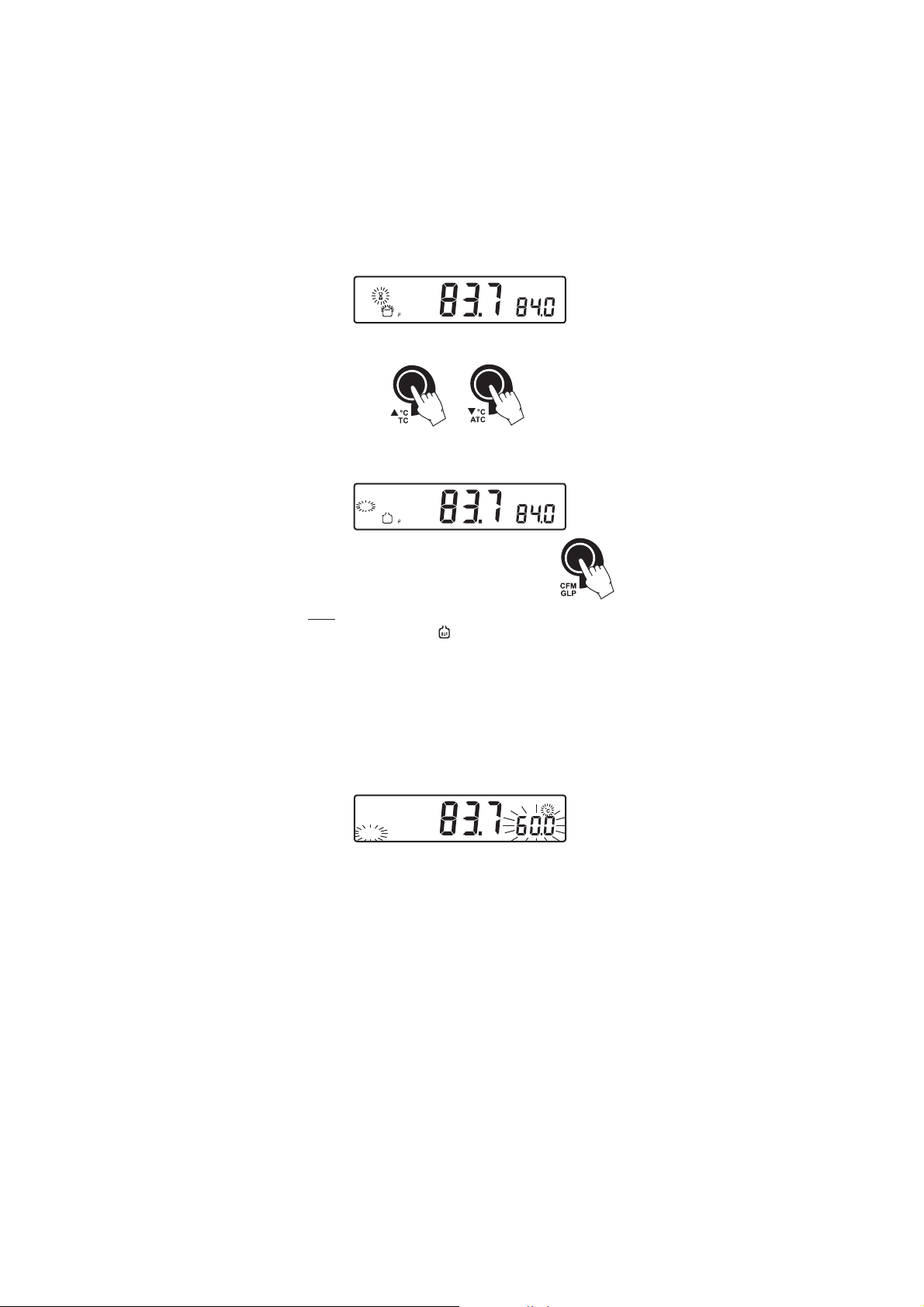
CAL
BUF
S
Select the desired value with the ARROW keys, if necessary.
When the reading is stable, “READY” tag is displayed and “CFM” tag
starts blinking on the LCD, asking for confirmation.
CAL
CFM
READY
BUF
S
Press CFM to confirm calibration.
The instrument stores the calibration value and returns
to measurement mode.
Notes: • If the reading is too far from the expected value, the
“WRONG” and “ ” tags will blink. Calibration can not be
confirmed.
In this case check if the calibration solution has been used or
clean the probe by following the Cleaning Procedure (see
page 53).
• If the meter is in ATC mode and the buffer temperature is
out of the 0.0 °C to 60.0 ºC interval, “WRONG” “ºC” tags
and the temperature will blink.
CAL
WRONG
• For best results choose an EC buffer value close to the sample
to be measured.
• In order to minimize any EMC interference, use plastic or
glass beakers.
• It is possible to set the cell constant value directly, without
following the calibration procedure. To set the cell constant,
enter SETUP mode and select “CEL” (see SETUP for details,
page 36).
20
Page 21

CONDUCTIVITY VERSUSCONDUCTIVITY VERSUS
CONDUCTIVITY VERSUS
CONDUCTIVITY VERSUSCONDUCTIVITY VERSUS
TEMPERATURE CHARTTEMPERATURE CHART
TEMPERATURE CHART
TEMPERATURE CHARTTEMPERATURE CHART
The conductivity of an aqueous solution is a measure of its ability to carry
an electrical current by means of ionic motion.
The conductivity invariably increases with increasing temperature.
It is affected by the type and number of ions in the solutions and by
the viscosity of the solution itself. Both parameters are temperature
dependent. The dependency of conductivity on temperature is
expressed as a relative change per Celsius degrees at a particular
temperature, commonly as %/ºC.
The following table lists the temperature dependence of HANNA EC
calibration buffers.
0307IH
1307IH
3307IH
4307IH
5307IH
CºFº
023 05176774600384004560672
514 02286985600535001470813
0105 033902017600695002385163
5195 0840174118600456005293604
618.06 0270137110700276004495514
716.26 0590199111700586003695424
814.46 0911152213700896002897334
912.66 03411152147003170020019244
0286 07611872167004270012013254
128.96 01911503187000470004017164
226.17 05121233197002570095011174
324.37 0932195311800567009701508
422.57 04621683128003870089012094
5277 08821314148000080081110005
628.87 03131044168003180083116905
726.08 073317641780003800751109
824.28 02631494198009480077116825
922.48 07831125109003680079113835
0368 02141845129002880081219745
138.78 07341575149000090093215
0308IH
1308IH
3308IH
(μ )mc/S
(μ )mc/S
(μ )mc/S
4308IH
(μ )mc/S
(μ )mc/S
9307IH
5308IH
9308IH
(μ )mc/S
4
15
755
21
Page 22

NaCl CALIBRATIONNaCl CALIBRATION
NaCl CALIBRATION
NaCl CALIBRATIONNaCl CALIBRATION
NaCl calibration is a one-point calibration at 100.0% NaCl. Use the
HI 7037L calibration solution (sea water solution) as a 100% NaCl
calibration solution.
Rinse the probe with some of the calibration solution or
deionized water. Submerse the probe into HI 7037L
solution. The sleeve holes must be completely submersed.
Tap the probe repeatedly to remove any air bubbles that
may be trapped inside the sleeve.
To enter NaCl calibration select the NaCl range and press
CAL.
The “BUF” and “CAL” tags are displayed. The primary LCD will display
the NaCl reading in percentage. The secondary LCD will display “100”.
CAL
NaCl
BUF
The “
” and “~” tags will blink.
%
When the reading is stable, the “READY” tag will be displayed and the
“CFM” tag starts blinking on the LCD, asking for confirmation.
CAL
CFM
READY
NaCl
BUF
%
Press CFM to confirm calibration.
The instrument stores the calibration value and returns to
measurement mode.
Notes: • If the reading is too far from the expected value, “WRONG”
“ ” tags will blink. Calibration cannot be confirmed.
• If the temperature of the buffer is out of the 0.0 ºC to 60.0 ºC
temperature interval, the “WRONG” and “ºC” tags and
the temperature will blink.
• If a new EC calibration is performed, the NaCl calibration is
automatically cleared. A new NaCl calibration is required.
22
Page 23

GOOD LABORATORY PRACTICE (GLP)GOOD LABORATORY PRACTICE (GLP)
GOOD LABORATORY PRACTICE (GLP)
GOOD LABORATORY PRACTICE (GLP)GOOD LABORATORY PRACTICE (GLP)
GLP is a set of functions that allows storage and retrieval of data
regarding the maintenance and status of the electrode.
All data regarding pH, Rel mV, EC and NaCl calibration is stored for the
user to review when necessary.
EXPIRED CALIBRATIONEXPIRED CALIBRATION
EXPIRED CALIBRATION
EXPIRED CALIBRATIONEXPIRED CALIBRATION
For pH calibration, this instrument allows the user to set the number of
days before the next required pH calibration. This value can be set from
1 to 7 days. The default setting is OFF (disabled).
When calibration has expired the “CAL” and “INTV” tags will blink to
warn the user that the instrument should be recalibrated.
For example, if a 4 days time out has been selected, the instrument will
issue the alarm exactly 4 days after the last calibration.
If the expiration value is changed (e.g. to 5 days), then the alarm will
be immediately recalculated and appear 5 days after the last calibration.
Note: If the instrument was not calibrated, the “CAL” “INTV” tags will
be displayed even if the feature is disabled in SETUP menu.
pH pH
CALIBRATION DATACALIBRATION DATA
pH
CALIBRATION DATA
pH pH
CALIBRATION DATACALIBRATION DATA
Calibration data is stored automatically after a successful calibration.
To view the pH calibration data, press GLP when the instrument is in pH
(mV) measurement mode.
The instrument will display the time (hh:mm) of the last calibration.
Use the ARROW keys to scroll through the calibration data:
• The date (yyyy.mm.dd).
• The pH calibration offset.
mVCAL
23
Page 24

• The pH calibration slope (the GLP slope is the average of the calibration
slopes; the percentage is referred to the ideal value of 59.16 mV/pH).
• The calibration buffers in order.
The first pH calibration buffer:
The second pH calibration buffer:
The third pH calibration buffer:
CAL pH
BUF
The fourth pH calibration buffer:
CAL pH
BUF
The fifth pH calibration buffer:
CAL pH
BUF
Notes: • The “OLd” message displayed beside the pH value means
that this buffer was not used during last calibration. Press
and hold down the SETUP key if you want to see calibration
date (or time if old calibration was performed on the same
day as the current calibration).
• If “no bUF” message appears on the LCD, the instrument
informs you that calibration was performed in less than
three points.
CAL
BUF
• Calibration Expiration status:
- if disabled.
24
Page 25

- or the number of days until the calibration alarm will be displayed.
- or if expired (7 days ago).
CAL
INTV
• The instrument ID.
RR
elative mVelative mV
R
elative mV
RR
elative mVelative mV
CALIBRATION DATA CALIBRATION DATA
CALIBRATION DATA
CALIBRATION DATA CALIBRATION DATA
Relative mV calibration data is stored automatically after a successful
calibration.
To view the Relative mV calibration data, press GLP when the instrument
is in Relative mV measurement mode.
The instrument will display the time (hh:mm) of the last calibration.
CAL
TIME
Use the ARROW keys to scroll through the calibration data:
• The date (yyyy:mm:dd).
• The Relative mV calibration offset.
• The instrument ID.
25
Page 26

EC CALIBRATION DATAEC CALIBRATION DATA
EC CALIBRATION DATA
EC CALIBRATION DATAEC CALIBRATION DATA
EC calibration data is stored automatically after a successful calibration.
To view the EC calibration data, press GLP when the instrument is in EC
measurement mode.
The instrument will display the time (hh:mm) of the last calibration.
Use the ARROW key to scroll through the calibration data:
• The date (yyyy:mm:dd).
• The EC calibration buffer.
• The cell constant.
• The calibration offset factor.
• The reference temperature.
• The temperature coefficient.
26
Page 27

• The temperature compensation mode.
• The instrument ID.
NN
aClaCl
CALIBRATION DATA CALIBRATION DATA
N
aCl
CALIBRATION DATA
NN
aClaCl
CALIBRATION DATA CALIBRATION DATA
NaCl calibration data is stored automatically after a successful calibration.
To view the NaCl calibration data, press GLP when the instrument is in
NaCl measurement mode.
The instrument will display the time (hh:mm) of the last calibration.
Use the ARROW key to scroll through the calibration data:
• The date (yyyy:mm:dd).
• The salinity coefficient.
• The cell constant.
• The reference temperature.
27
Page 28

• The temperature compensation mode.
• The instrument ID.
Notes: • If no temperature compensation is selected during calibration,
the temperature coefficient is not displayed in GLP.
• Press GLP at any moment and the instrument will return to
measurement mode.
• If calibration has not been performed on the selected range,
the instrument displays “no CAL” message blinking.
CAL
LOGGING FUNCTIONLOGGING FUNCTION
LOGGING FUNCTION
LOGGING FUNCTIONLOGGING FUNCTION
Up to 700 logged samples can be stored into memory.
200 manually logged records and 500 lot logging records can be stored
in the memory. To select logging type enter SETUP menu.
LOGGING THE CURRENT DATA LOGGING THE CURRENT DATA
LOGGING THE CURRENT DATA
LOGGING THE CURRENT DATA LOGGING THE CURRENT DATA
(manual logging)(manual logging)
(manual logging)
(manual logging)(manual logging)
Select the manual logging mode in SETUP menu.
To store the current reading into memory press LOG while the instrument
is in measurement mode.
The instrument will display “MAn” on the primary LCD, the record
number on the secondary LCD and “LOG” tag for a few seconds (see
example below: record No. 15):
28
Page 29

followed by the number of free records:
If there are less than 6 memory locations remaining, the record number
and “Lo” message will be displayed to alert the user.
If the log space is full (200 records), “FULL LOG” message will be
displayed and no more data will be saved.
When LOG is pressed, a complete set of information is stored: date, time,
pH, mV, EC, TDS, NaCl temperature and calibration data.
LOT LOGGINGLOT LOGGING
LOT LOGGING
LOT LOGGINGLOT LOGGING
Select “StAb” (stability logging) or the desired time interval.
To start interval logging press LOG key while the instrument is in
measurement mode.
When the selected interval is reached or when the reading is stable (for
log on stability), the instrument will display the current lot number on
the primary LCD line, the record number on the secondary LCD line and
the LOG tag (see example below: Lot 5 record 7)
followed by the number of free records on the corresponding memory
space.
If stability logging is selected, a complete set of data is memorized every
time the reading becomes stable after an unstable condition.
To stop interval logging press LOG key again. The “LOG” tag will be
cleared.
Note: When pressing any key that is not active, while lot logging is
running, the following message is displayed for a few seconds.
29
Page 30

VIEW LOGGED DATAVIEW LOGGED DATA
VIEW LOGGED DATA
VIEW LOGGED DATAVIEW LOGGED DATA
Press the ALT&RCL
keys while in measurement mode to retrieve the
stored information.
If no data was logged for the current selected measurement range and
no lots are memorized, one of the next messages will be displayed:
LOG
No pH measurements records:
LOG
No Relative mV and mV records:
LOG mV
No EC records:
LOG
No TDS records:
LOG
No NaCl records:
LOG
Otherwise, the instrument will display the lot number on the primary LCD
line, the number of records on the secondary, “LOG” tag and “CFM”
blinking. If samples were logged on demand “MAn” will be displayed on
the primary LCD and the number of samples logged on the secondary
(see example below: manual log, 15 samples logged).
Press ARROW keys to select different lot.
30
Page 31

Press CFM to view record information.
• If RCL was entered while in pH measurement range:
pHLOG
In Rel mV range:
In EC measurement range:
In TDS measurement range:
In NaCl measurement range:
Use the ARROW keys to scroll through the records.
31
Page 32

Note: The instrument will automatically skip log records from other
measurement ranges.
To view additional information press RANGE:
For pH
• The mV value on the primary LCD and the temperature value on the
secondary LCD.
• The time on the primary LCD, along with “TIME” tag and the record
number on the secondary LCD.
LOG
TIME
• The date on the primary LCD, along with “DATE” tag.
• The calibration offset on the primary LCD and “OFS” message on
the secondary LCD.
mVLOG
• The calibration slope on the primary LCD and “SLP” message on
the secondary LCD.
LOG
%
• The interval for lot logging.
To delete manual logged records: press CFM while “ MAn” is displayed to
view manually logged records. Press the CLR key, “dEL” and the record
number will be displayed. Press CFM to delete. Use the ARROW keys to
change the record number.
To delete a lot, use the ARROW keys to select the desired lot. Press CLR
key, “dEL LOt” will appear on the display. Press CFM key to delete.
32
Page 33

The “dEL” message is displayed on the primary LCD and the selected record
on the secondary LCD, along with ”LOG” tag.
• The ARROW keys can be used to change the record or lot number.
• Press SETUP to delete all records/lots. The display will show “dEL” in
the primary LCD and “ALL” in the secondary LCD.
• Press CFM to confirm delete. While deleting the “ ” tag will blink.
• Press CAL or RANGE or CLR to escape and return to the RCL screen.
• If “del ALL” option was selected, all the log on demand records or lots
are deleted. While deleting the “ ” tag is displayed blinking.
• Press ALT&RCL exit record information and enter lot information.
• Press ALT&RCL again to return to measurement mode.
• If one or more records/lots were deleted the “ ” tag blinks until the
log memory space is reorganized.
Note: If at least one record was deleted the log memory space will be
recognized in about 4-5 seconds. During this period the “ ” will
blink.
For Relative mV and mV Range
• The temperature value, the mV absolute value, the time and the
date as described above.
• The Relative mV offset.
mVLOG
For EC Range
• The time and date as described on pH Range.
• The EC on primary LCD and temperature value on the secondary LCD.
• The offset factor on the primary LCD and “OFS” message on the
secondary LCD.
33
Page 34

• The cell constant on the primary LCD and “CEL” message on the
secondary LCD line.
• The reference temperature on the primary LCD and “rEF”
message on the secondary LCD.
• The temperature coefficient on the primary LCD and “tc” message
on the secondary LCD.
• The temperature compensation mode.
For TDS Range
• The temperature reading as described in pH range.
• The conductivity value on the primary LCD and the temperature
value on the secondary LCD.
• The time and the date as described in pH Range.
• The TDS factor on the primary LCD and “cF” message on the
secondary LCD.
• The reference temperature, the temperature coefficient,
the temperature compensation mode and the cell constant as
described in EC Range.
34
Page 35

For NaCl Range
• The conductivity and temperature reading value as described in TDS
Range.
• The time and date as described in pH Range.
• The salinity factor on the primary LCD and “cF” message on the
secondary LCD, with “LOG” and “NaCl” tags displayed.
• The reference temperature, the temperature compensation mode
and the cell constant message as described above.
LOG
NaCl
Note: After LOG is pressed or “dEL” is confirmed, the instrument will
display the amount of free log space for about one second
(example 25 records free).
Press the ALT&RCL keys to leave RECALL mode at any time.
Note: When an information that does not display the record number
is selected, pressing the SETUP key will display the record
number on the secondary LCD line.
35
Page 36

SETUPSETUP
SETUP
SETUPSETUP
Setup mode allows viewing and modifying the following instrument
parameters.
In according with the selected range, SETUP menu allows the possibility
to view and /or change specific range parameters and common parameters
(for all the ranges).
The common parameters are:
• Log interval
• Current Time (hour & minute)
• Current Date (year, month & day)
• Beep Status
• Instrument Id
• Temperature Unit
The specific parameters are:
In pH range
• Expired Calibration Alarm
• First Custom Buffer
• Second Custom Buffer
• One-point Calibration Behavior
• pH Resolution
In EC/TDS/NaCl range
• Cell Constant
• TDS Factor
• Temperature Compensation Coefficient
• Reference Temperature
To enter SETUP mode press SETUP while the instrument is in measurement
mode.
Select a parameter with the ARROW keys.
Press CAL to change a parameter value. The selected parameter will
start blinking.
Press RANGE to toggle between displayed parameters.
Press the ARROW keys to increase or decrease the displayed value.
Press CFM to save the modified value or CAL to escape without saving.
36
Page 37

EXPIRED CALIBRATION ALARMEXPIRED CALIBRATION ALARM
EXPIRED CALIBRATION ALARM
EXPIRED CALIBRATION ALARMEXPIRED CALIBRATION ALARM
Press CAL when the calibration time-out is displayed. Calibration
time-out (“OFF” or “1” to “7” days) will start blinking.
Press the ARROW
Press CFM to save the modified calibration time-out value.
Press CAL to escape without saving.
LOG INTERVALLOG INTERVAL
LOG INTERVAL
LOG INTERVALLOG INTERVAL
Press CAL when log interval is displayed. The log interval is selected
blinking (“MAn” for log on demand, “StAb” log on stability, interval in
seconds or minutes).
Press the ARROW keys to change the custom buffer value.
Press CFM to confirm the selection.
Press CAL to escape without saving.
FIRST CUSTOM BUFFERFIRST CUSTOM BUFFER
FIRST CUSTOM BUFFER
FIRST CUSTOM BUFFERFIRST CUSTOM BUFFER
Press CAL when “cb1” is displayed. The custom buffer (disabled – “no”
or “0” to “16” pH) will start blinking.
Press the ARROW keys to change the custom buffer value.
Press CFM to save the modified custom buffer value.
Press CAL to escape without saving.
SECOND CUSTOM BUFFERSECOND CUSTOM BUFFER
SECOND CUSTOM BUFFER
SECOND CUSTOM BUFFERSECOND CUSTOM BUFFER
Press CAL when “cb2” is displayed. The custom buffer (disabled – “no”
or “0” to ”16” pH) will start blinking.
keys to change the calibration time-out value.
Press the ARROW keys to change the custom buffer value.
Press CFM to save the modified custom buffer value.
Press CAL to escape without saving.
37
Page 38

Note: To remove a custom buffer from the calibration list enter custom
buffer press CAL key then press CLR key. The “no” “cb1” or “cb2”
message will be displayed and the instrument return for the
SETUP parameter scroll mode.
ONE-POINT CALIBRATION BEHAVIORONE-POINT CALIBRATION BEHAVIOR
ONE-POINT CALIBRATION BEHAVIOR
ONE-POINT CALIBRATION BEHAVIORONE-POINT CALIBRATION BEHAVIOR
Press CAL when “1 Pnt” message is displayed on the secondary LCD.
One of the two options (“Pnt” or “OFFS”) will start blinking (see pH
CALIBRATION PROCEDURE for details, page 13).
Press the ARROW keys to toggle between “Pnt” and “OFFS” options.
Press CFM to save the behavior for one-point calibration.
Press CAL to escape without saving.
pH RESOLUTIONpH RESOLUTION
pH RESOLUTION
pH RESOLUTIONpH RESOLUTION
Press CAL when “rES” message is displayed on the secondary LCD. The
set resolution (“0.1”, “0.01” or “0.001”) will start blinking.
Press the ARROW keys to toggle between 0.1, 0.01 and 0.001 options.
Press CFM to save the modified value.
Press CAL to escape without saving.
CURRENT TIMECURRENT TIME
CURRENT TIME
CURRENT TIMECURRENT TIME
Press CAL when the current time is displayed. The hour will start blinking.
Press the ARROW
Press RANGE. The minutes will start blinking.
Press the ARROW keys to change the minutes.
Press CFM to save the modified value.
Press CAL to escape without saving.
keys to change the hour.
38
Page 39

CURRENT DATECURRENT DATE
CURRENT DATE
CURRENT DATECURRENT DATE
Press CAL when the current date is displayed. The year will start blinking.
Press the ARROW
Press RANGE. The month will start blinking.
Press the ARROW
Press RANGE. The day will start blinking.
Press the ARROW keys to change the day.
Press CFM to save the modified value.
Press CAL to escape without saving.
BEEP STATUSBEEP STATUS
BEEP STATUS
BEEP STATUSBEEP STATUS
Press CAL when the beep status is displayed. Beep status (“On” or
“OFF”) will start blinking.
Press the ARROW
Press CFM to save the modified beep status.
Press CAL to escape without saving.
When enable, beep sounds as a short beep every time a key is pressed or
when the calibration can be confirmed.
A long beep alert that the pressed key is not active or a wrong condition
is detected while in calibration.
keys to change the year.
keys to change the month.
keys to change the beep status (On or OFF).
39
Page 40

II
NSTRUMENT IDNSTRUMENT ID
I
NSTRUMENT ID
II
NSTRUMENT IDNSTRUMENT ID
Press CAL when “InId” is displayed. The instrument ID (“0000“ to
“9999“) will start blinking.
Press the ARROW
Press CFM to save the modified instrument ID value.
Press CAL to escape without saving.
Note: The instrument ID is downloaded to a PC as part of a logged
data, set to identify its origin.
TEMPERATURE UNITTEMPERATURE UNIT
TEMPERATURE UNIT
TEMPERATURE UNITTEMPERATURE UNIT
Press CAL when “tnP“ is displayed. The temperature unit will start
blinking.
Press the ARROW keys to change the option.
Press CFM to save the modified temperature unit.
Press CAL to escape without saving.
CELL CONSTANTCELL CONSTANT
CELL CONSTANT
CELL CONSTANTCELL CONSTANT
Press CAL when the cell constant is displayed. The cell constant will start
blinking.
keys to change the instrument ID value.
Press the ARROW keys to change the cell constant (0.500 to 1.700).
Press CFM to save the modified cell constant.
Press CAL to escape without saving.
40
Page 41

TDS FACTORTDS FACTOR
TDS FACTOR
TDS FACTORTDS FACTOR
Press CAL when “tdS” is displayed. The TDS factor will start blinking.
Press the ARROW keys to change the TDS factor (0.40 to 0.80).
Press CFM to save the modified TDS factor.
Press CAL to escape without saving.
TEMPERATURE COMPENSATION COEFFICIENTTEMPERATURE COMPENSATION COEFFICIENT
TEMPERATURE COMPENSATION COEFFICIENT
TEMPERATURE COMPENSATION COEFFICIENTTEMPERATURE COMPENSATION COEFFICIENT
Press CAL when the temperature compensation coefficient is displayed.
The temperature compensation coefficient will start blinking.
Press the ARROW keys to change the temperature compensation
coefficient. (0.00 to 6.00 %/ºC).
Press CFM to save the modified temperature compensation coefficient.
Press CAL to escape without saving.
REFERENCE TEMPERATUREREFERENCE TEMPERATURE
REFERENCE TEMPERATURE
REFERENCE TEMPERATUREREFERENCE TEMPERATURE
Press CAL when the reference temperature is displayed. The reference
temperature will start blinking.
Press the ARROW keys to toggle between 20.0 ºC and 25.0 ºC reference
temperature value.
Press CFM to save the modified reference temperature value.
Press CAL to escape without saving.
41
Page 42
TEMPERATURE CALIBRATIONTEMPERATURE CALIBRATION
TEMPERATURE CALIBRATION
TEMPERATURE CALIBRATIONTEMPERATURE CALIBRATION
((
for technical personnel onlyfor technical personnel only
(
for technical personnel only
((
for technical personnel onlyfor technical personnel only
The instrument has two temperature channels: one that measures the
temperature from the HI 7662 probe while the instrument is in pH/mV
range and the other that measures temperature from the EC probe while
the instrument is in EC/TDS/NaCl range.
All the instruments are factory calibrated for temperature on both channels.
Hanna’s temperature probes are interchangeable and no temperature
calibration is needed when they are replaced.
If the temperature measurements are inaccurate, temperature recalibration
should be performed.
For an accurate recalibration, contact your dealer or the nearest Hanna
Customer Service Center, or follow the instructions below.
• Prepare a vessel containing ice and water and another one containing
hot water (around 50 ºC). Place insulation material around the vessels
to minimize temperature changes.
• Use a calibrated thermometer with a resolution of 0.1 ºC as a
reference thermometer. Connect the HI 7662 probe to the appropriate
socket for the pH temperature channel or the HI 76310 probe for the
EC temperature channel.
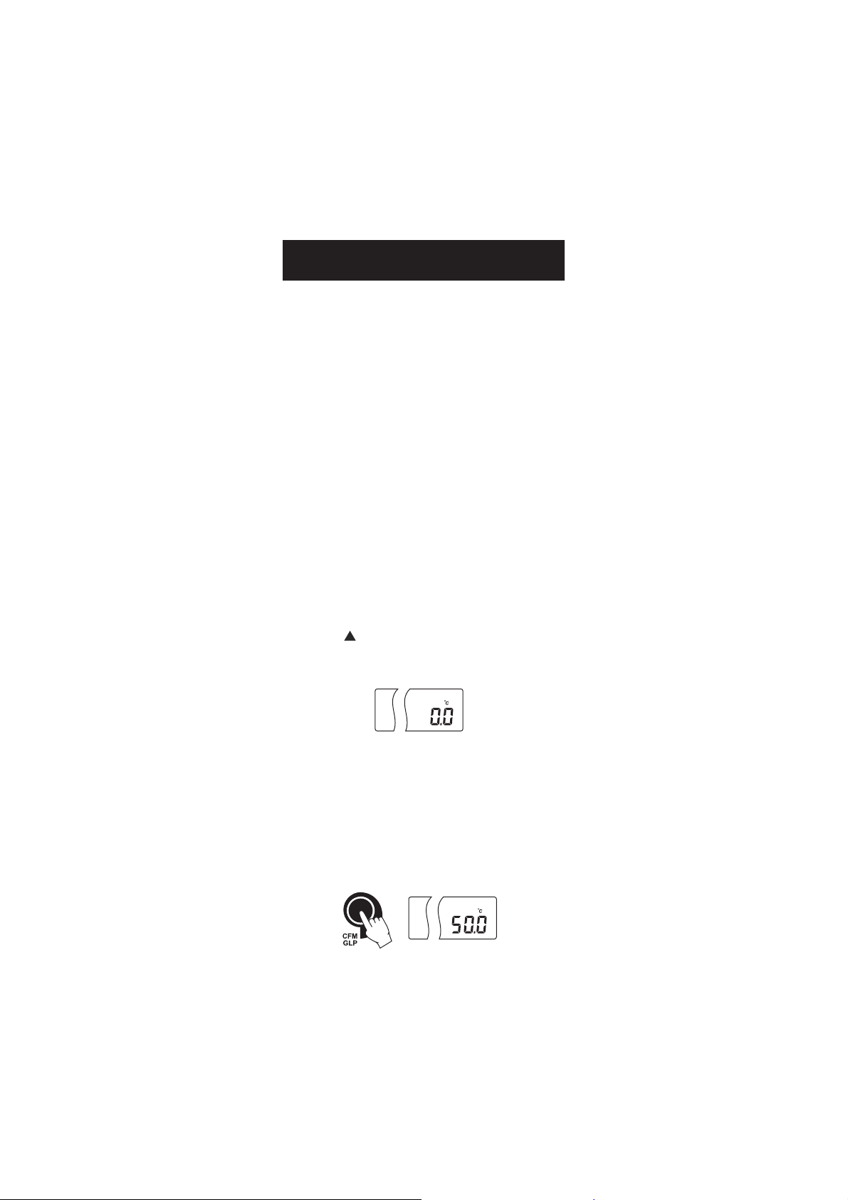
• With the instrument off, press and hold down the CFM & SETUP
keys, then power on the instrument to calibrate the pH temperature
channel or &RANGE keys and then power on the instrument to
calibrate the EC temperature channel. The “CAL” tag will appear
and the secondary LCD will show “0.0 ºC“.
CAL
))
)
))
• Submerse the temperature probe (or EC probe) in the vessel with ice
and water as near as possible to the calibrated thermometer. Allow
a few seconds for the probe to stabilize.
• Use the ARROW keys to set the reading on the secondary LCD to that
of ice and water, measured by the calibrated thermometer. When
the reading is stable and close to the selected calibration point,
“READY” tag will appear and “CFM” tag will blink.
• Press CFM to confirm. The secondary LCD will show “50.0 ºC“.
CAL
42
Page 43

• Submerse the temperature probe (or EC probe) in the second vessel
as near as possible to the calibrated thermometer. Allow a few
seconds for the probe to stabilize.
• Use the ARROW keys to set the reading on the secondary LCD to that
of the hot water.
• When the reading is stable and close to the selected
calibration point, “READY” tag will appear and
“CFM” tag will blink.
• Press CFM to confirm. The instrument memorize
calibration and restart in measurement mode.
Note: If the reading is not close to the selected calibration point,
“WRONG” tag will blink. Change the temperature probe (or EC
probe) and restart calibration.
43
Page 44

mm
V CALIBRATIONV CALIBRATION
m
V CALIBRATION
mm
V CALIBRATIONV CALIBRATION
((
for technical personnel onlyfor technical personnel only
(
for technical personnel only
((
for technical personnel onlyfor technical personnel only
All the instruments are factory calibrated for mV.
Hanna’s ORP electrodes are interchangeable and no mV calibration is
needed when they are replaced.
If the mV measurements are inaccurate, mV recalibration should be
performed.
For an accurate recalibration, contact your dealer or the nearest Hanna
Customer Service Center or follow the instructions below.
A two-point calibration can be performed at 0.0 mV and 1800.0 mV.
• Attach to the BNC connector a mV simulator with an accuracy of
±0.1 mV.
• With the instrument off, press and hold down the CAL & keys,
then power on the instrument. The “CAL” tag will appear and the
secondary LCD will show “0.0 mV“.
• Set 0.0 mV on the simulator.
When the reading is stable and close to the selected calibration
point, “READY” tag will appear and “CFM” tag will blink.
• Press CFM to confirm. The secondary LCD will display “1800 mV“.
• Set 1800.0 mV on the simulator.
When the reading is stable and close to the selected calibration
point, “READY” tag will appear and “CFM” tag will blink.
• Press CFM to confirm. The instrument memorize calibration and
restart to measurement mode.
Notes:• If the reading is not close to the selected calibration point,
“WRONG” tag will blink. Verify calibration condition or
contact your vendor if you can not calibrate.
• Pressing CAL key during calibration process the instrument
quit calibration mode and restart to measurement mode
without memorizing calibration.
))
)
))
44
Page 45

PC INTERFACEPC INTERFACE
PC INTERFACE
PC INTERFACEPC INTERFACE
Data transmission from the instrument to the PC can be done with
the HI 92000 Windows® compatible software (optional). HI 92000
also offers graphing and on-line help feature.
Data can be exported to the most popular spreadsheet programs for
further analysis.
To connect your instrument to a PC, use a standard USB cable connector.
Make sure that your instrument is switched off and plug one connector to
the instrument USB socket and the other to the USB port of your PC.
Note: If you are not using Hanna Instruments HI 92000 software,
please see the following instructions.
SENDING COMMANDS FROM PCSENDING COMMANDS FROM PC
SENDING COMMANDS FROM PC
SENDING COMMANDS FROM PCSENDING COMMANDS FROM PC
It is also possible to remotely control the instrument with any terminal
program. Use a standard USB cable to connect the instrument to a PC,
start the terminal program and set the communication options as follows:
8, N, 1, no flow control, 9600 baud rate.
COMMAND TYPESCOMMAND TYPES
COMMAND TYPES
COMMAND TYPESCOMMAND TYPES
To send a command to the instrument the scheme is:
<command prefix> <command> <CR>
where: <command prefix> is a selectable ASCII character
between 0 and 47.
<command> is the command code (3 characters).
Note: Either small or capital letters can be used.
SIMPLE COMMANDSSIMPLE COMMANDS
SIMPLE COMMANDS
SIMPLE COMMANDSSIMPLE COMMANDS
RNG Is equivalent to pressing RANGE
CAL Is equivalent to pressing CAL
CFM Is equivalent to pressing CFM
UPC Is equivalent to pressing the UP arrow key
DWC Is equivalent to pressing the DOWN arrow key
SET Is equivalent to pressing SETUP
LOG Is equivalent to pressing LOG
MOD Is equivalent to pressing MODE
GLP Is equivalent to pressing GLP
CLR Is equivalent to pressing CLR
RCL Is equivalent to pressing RCL
45
Page 46

CHRxx Change the instrument range according with the parameter
value (xx):
• xx=00 pH range/0.001 resolution
• xx=01 pH range/0.01 resolution
• xx=02 pH range/0.1 resolution
• xx=03 mV range
• xx=04 Relative mV range
• xx=06 EC range
• xx=07 TDS range
• xx=08 NaCl range
The instrument sends the “ACK” (6) character every time a command is
recognized and a “NAK” (21) character for invalid commands.
COMMANDS REQUIRING AN ANSWERCOMMANDS REQUIRING AN ANSWER
COMMANDS REQUIRING AN ANSWER
COMMANDS REQUIRING AN ANSWERCOMMANDS REQUIRING AN ANSWER
RAS Causes the instrument to send a complete set of readings in
according with the current range:
• pH, mV and temperature reading on pH range.
• mV and temperature reading on mV range.
• Rel mV, absolute mV and temperature reading on
Rel mV range.
• Conductivity and temperature reading on EC range.
• TDS and temperature reading on TDS range.
• NaCl and temperature reading on NaCl range.
The answer string contains:
• Meter mode (2 chars):
• 00 - pH range (0.001 resolution)
• 01 - pH range (0.01 resolution)
• 02 - pH range (0.1 resolution)
• 03 - mV range
• 04 - Rel mV range
• 06 - EC range
• 07 - TDS range
• 08 - NaCl range
• Meter status (2 chars of status byte): represents a 8
bit hexadecimal encoding.
• 0x10 - temperature probe is connected
• 0x01 - new GLP data available
• 0x02 - new SETUP parameter
46
Page 47

• Reading status (2 chars): R - in range, O - over
range, U - under range. First character corresponds
to the appropriate range reading. Second character
corresponds to mV reading (if exist).
• Primary reading (corresponding to the selected range)
- 7 ASCII chars, including sign and decimal point.
• Secondary reading (only when primary reading is not
mV, EC, NaCl, TDS) - 7 ASCII chars, including sign and
decimal point.
• Temperature reading - 8 ASCII chars, with sign and
two decimal points, always in ºC.
MDR Requests the instrument model name and firmware code.
GLP Requests the calibration data record.
The answer string contains:
• GLP status (1 char): represents a 4 bit hexadecimal
encoding.
• 0x01 - pH calibration available
• 0x02 - Rel mV calibration available
• 0x04 - EC calibration available
• 0x08 - NaCl calibration available
• pH calibration data (if available), which contains:
• the number of calibrated buffers (1 char)
• the offset, with sign and decimal point (7 chars)
• the average of slopes, with sign and decimal point
(7 chars)
• the calibration time, yymmddhhmmss (12 chars)
• buffers information (for each buffer)
• type (1 char): 0 - standard, 1 - custom
• status (1 char): N (new) - calibrated in last
calibration; O (old) - from an old calibration.
• warnings during calibration (2 chars): 00 - no
warning, 04 - Clean Electrode warning.
• buffer value, with sign and decimal point
(7 chars).
• the calibration time, yymmddhhmmss (12 chars).
• Rel mV calibration data (if available), which contains:
• the calibration offset, with sign (7 chars)
• the calibration time, yymmddhhmmss (12 chars).
47
Page 48

• EC calibration data (if available), which contains:
• the number of calibrated standards (1 char)
• the offset factor, with sign and decimal point
(7 chars)
• the cell constant, with sign and decimal point
(7 chars)
• the calibration time, yymmddhhmmss (12 chars)
• standards information (for each standard)
• standard value, with sign and decimal point
(7 chars).
• buffer unit (2 chars; 00-μS; 01-mS)
• Reference Temperature with and decimal point
(4 chars)
• Temperature Compensation mode (2 chars)
• 00 - no temperature compensation
• 01 - automatic tempe rature compensation
• 00 - manual temperature compensation
• TC coeficient with sign and decimal point (4 chars)
• calibration time, yymmddhhmmss (12 chars).
• Na Cl Calibration data
• the number of calibrated data (1 char)
• salinity coeficient, with sign and decimal point
(7 chars)
• Cell constant, with sign and decimal point
(2 chars)
• the calibration time (2 chars)
• buffer information, for each buffer:
• Reference Temperature with and decimal point
(4 chars)
• Temperature Compensation mode (2 chars)
• 00 - no temperature compensation
• 01 - automatic tempe rature compensation
• 00 - manual temperature compensation
• TC coeficient with sign and decimal point (4 chars)
• calibration time, yymmddhhmmss (12 chars).
PAR Requests the setup parameters setting.
The answer string contains:
• Instrument ID (4 chars)
48
Page 49

• Calibration alarm time out for pH range (2 chars)
• SETUP information (2 chars): 8 bit hexadecimal
encoding.
• 0x01 - beep ON (else OFF)
• 0x04 - degrees Celsius (else degrees Fahrenheit)
• 0x08 - Offset calibration (else Point calibration)
• The number of custom buffers (1 char)
• The custom buffer values, with sign and decimal
point, for each defined custom buffer (7 chars)
• Log type 2 chars
01 - manual log
02 - stability lot log
03 to 14 - the coresponding interval for lot log (5 s
to 180 min)
• cell constant, with sign and decimal point (6 chars)
• TDS factor, with sign and decimal point (5 chars)
• TC coef, with sign and decimal point (5 chars)
• Reference Temperature, with sign and decimal point
(5 chars)
• Temperature Compensation mode (1 char)
NSLx Requests the number of logged samples.
x = P - request for pH range
M - request for mV range
E - request for EC range
N - request for NaCl range
T - request for TDS range
LODxnnn: request the”nnn” record of the manual log on the “x” range
LODxALLff: groups all Log On Demand Records in frames of 8 records
each for the selected range
Command Parameters:
x - range (see Note)
ALL - download all records for the selected range
ff - requested frame number - first frame is labeled 01
LLsxff: requests information about all lots on the specified range, it sends
the information in frames of 10 lots each (a frame contains information
about 10 lots)
Command Parameters:
x - range (see Note)
ff - requested frame number - first frame is labeled 01
49
Page 50

GLDxxxff: Requests the records of the “xxx” lot number. The records are
sent in frames of 10 records; “ff” is the frame number (01 first
frame). (Example: Lot 13 has 53 records. The records will be
sent in 6 frame, 5 with10 records and 1 with 3 records.)
Command Parameters:
xxx - Lot number (eq: for lot number 1 xxx = 001)
ff - requested frame number - first frame is labeled 01
Errors:• “Err3” log on demand empty.
• “Err4” requested set parameter is not available.
• “Err5” command argument is wrong.
• “Err6” requested range not available.
• “Err7” meter in log mode.
• “Err8” is sent if instrument is not in measurement mode.
• “NAK” (21) character is sent when the instrument receives
an unknown or a corrupted command.
Note: P - request for pH range.
M - request for mV range.
E - request for EC range.
T - request for TDS range.
N - request for NaCl range.
50
Page 51

ELECTRODE CONDITIONINGELECTRODE CONDITIONING
ELECTRODE CONDITIONING
ELECTRODE CONDITIONINGELECTRODE CONDITIONING
& MAINTENANCE& MAINTENANCE
& MAINTENANCE
& MAINTENANCE& MAINTENANCE
PREPARATION PROCEDUREPREPARATION PROCEDURE
PREPARATION PROCEDURE
PREPARATION PROCEDUREPREPARATION PROCEDURE
Remove the protective cap of the pH electrode.
DO NOT BE ALARMED IF SALT DEPOSITS ARE PRESENT. This is normal
with electrodes. They will disappear when rinsed with water.
During transport, tiny bubbles of air may form inside the glass bulb
affecting proper functioning of the electrode. These bubbles can be
removed by “shaking down” the electrode as you would do with a glass
thermometer.
If the bulb and/or junction is dry, soak the electrode in HI 70300 or
HI 80300
Storage Solution for at least one hour.
51
Page 52

For refillable electrodes:For refillable electrodes:
For refillable electrodes:
For refillable electrodes:For refillable electrodes:
If the filling solution (electrolyte) is more than 2½ cm (1”) below the fill
hole, add HI 7082 or HI 8082 3.5M KCl Electrolyte Solution for double
junction or HI 7071 or HI 8071 3.5M KCl+AgCl Electrolyte Solution for
single junction electrodes.
For faster response, unscrew the fill hole screw during measurements.
®®
®
For AMPHELFor AMPHEL
For AMPHEL
For AMPHELFor AMPHEL
®®
electrodes: electrodes:
electrodes:
electrodes: electrodes:
If the electrode does not respond to pH changes, the battery is run down
and the electrode should be replaced.
MEASUREMENTMEASUREMENT
MEASUREMENT
MEASUREMENTMEASUREMENT
Rinse the pH electrode tip with distilled water. Submerse the tip (3 cm /1¼”)
in the sample and stir gently for a few seconds.
For a faster response and to avoid cross-contamination of the samples,
rinse the electrode tip with a few drops of the solution to be tested, before
taking measurements.
Take care that the sleeve holes of the EC probe are completely submersed.
Tap the probe repeatedly to remove air bubbles that may be trapped
inside the sleeve.
STORAGE PROCEDURESTORAGE PROCEDURE
STORAGE PROCEDURE
STORAGE PROCEDURESTORAGE PROCEDURE
To minimize clogging and assure a quick response time, the glass bulb
and the junction of pH electrode should be kept moist and not allowed to
dry out.
Replace the solution in the protective cap with a few drops of HI 70300
or HI 80300 Storage Solution or, in its absence, Filling Solution
(HI 7071 or HI 8071 for single junction and HI 7082 or HI 8082 for
double junction electrodes). Follow the Preparation Procedure on page
53 before taking measurements.
Note: NEVER STORE THE ELECTRODE IN DISTILLED OR DEIONIZED WATER.
PERIODIC MAINTENANCEPERIODIC MAINTENANCE
PERIODIC MAINTENANCE
PERIODIC MAINTENANCEPERIODIC MAINTENANCE
Inspect the electrode and the cable. The cable used for connection to the
instrument must be intact and there must be no points of broken
insulation on the cable or cracks on the electrode stem or bulb. Connectors
must be perfectly clean and dry. If any scratches or cracks are present,
replace the electrode. Rinse off any salt deposits with water.
pH Electrode Maintenance
For refillable electrodes:For refillable electrodes:
For refillable electrodes:
For refillable electrodes:For refillable electrodes:
Refill the reference chamber with fresh electrolyte (HI 7071 or HI 8071 for
single junction and HI 7082 or HI 8082 for double junction electrodes).
Allow the electrode to stand upright for 1 hour.
Follow the Storage Procedure above.
52
Page 53

pH pH
ELECTRODE CLEANING PROCEDUREELECTRODE CLEANING PROCEDURE
pH
ELECTRODE CLEANING PROCEDURE
pH pH
ELECTRODE CLEANING PROCEDUREELECTRODE CLEANING PROCEDURE
• General Soak in Hanna HI 7061 or HI 8061 General Cleaning
Solution for approximately ½ hour.
• Protein Soak in Hanna HI 7073 or HI 8073 Protein Cleaning
Solution for 15 minutes.
• Inorganic Soak in Hanna HI 7074 Inorganic Cleaning Solution
for 15 minutes.
• Oil/grease Rinse with Hanna HI 7077 or HI 8077 Oil and Fat
Cleaning Solution.
IMPORTANT: After performing any of the cleaning procedures, rinse the
electrode thoroughly with distilled water, refill the reference chamber
with fresh electrolyte (not necessary for gel-filled electrodes) and soak the
electrode in HI 70300 or HI 80300 Storage Solution for at least 1 hour
before taking measurements.
EC Probe MaintenanceEC Probe Maintenance
EC Probe Maintenance
EC Probe MaintenanceEC Probe Maintenance
Rinse the probe with clean water after measurements. If a more thorough
cleaning is required, remove the probe sleeve and clean the probe with
a cloth or a nonabrasive detergent. Make sure to reinsert the sleeve onto
the probe properly and in the right direction. After cleaning the probe,
recalibrate the instrument.
The platinum rings support is made of glass. Take great care while
handling the probe.
53
Page 54

TROUBLESHOOTING GUIDETROUBLESHOOTING GUIDE
TROUBLESHOOTING GUIDE
TROUBLESHOOTING GUIDETROUBLESHOOTING GUIDE
SMOTPMYSMELBORPNOITULOS
.Hpgnirusaem
.)esion(nwod
.noitarbilac
lpsidehtfI Hp "
"dna 00.2- "ro" 0.61 "0
.gniknilb
tfI Vm "
"dna 0002- "ro" 0002 "
.gniknilb
liafretemehT
.lCaN
d
.yltnenamrep
" xxrrE egassemrorre"
.deyalpsid
tfirdevissecxe/esnopserwolS
dnapuetautculfsgnidaeR
tpeccatonseodretemehT
rofnoitulosnoitarbilaceht
":swohsya
":swohsyalpsideh
SDT,CEswohsyalpsidehT
.gniknilbgnidaerlCaNro
krowtonseodretemehT
.eborperutarepmetehthtiw
etarbilacots
.sgnidaerytluafsevigro
etarbilacotsliafretemehT
retemehtputratstA
sgatDCLllasyalpsi
.edortceleHpytriDnipitedortceleehtkaoS
.)ylno
.eveels
.noitulos
.elacslCaN
.desu
.edortcelenekorB.edortceleehtecalpeR
.ro
rrelanretnInehtdnaretemehtfforewoP
.noitcnujytrid/deggolC
.no
itarbilacCEtcerrocnICEniretemehtetarbilaceR
tarbilacdetanimatnoc
leveletylortcelewoL
sedortceleHpelballifer(
ylreporptoneveelseborpCE
edisniselbbubria;detresni
.edortceleHpredrofotuO
roedortceleytriD
noi
.elacsHpehtniegnarfotuOa.retemehtetarbilaceR)
.elacsVmehtniegnarfotuOyfireV.detcennoctonedortcelE
roSDT,CEniegnarfotuO
roeborperutarepmetnekorB
eborperutarepmetgnorw
.dekcolbsisyekehtfoenOtcatnocrodraobyekehtkcehC
1607IH ro 1608IH 03rof
lC
rp
aM)b
aceR
.egnar
.eborp
.egnar
.edortcele
.edortcele
.edortcele
eehttaht
ehterusekaM KCOL sawyek
.desserpton
.rodneveht
ehtnae
lcnehtdnasetunim
.edortceleehtnae
rof(noituloshserfhtiwllifeR
.)ylnosedortceleHpelballifer
ehtpaT.eveelsehttresnI
.selbbubriaevomerotebo
.erudecorpgninaelcehtwolloF
ehtecalperstluseronllitsfI
elpmasHpehterusek
.egnardeificepsehtnisi
leveletylortceleehtkcehC)c
ehtfoetatslarenegehtdna
.tcennocsiedortcel
ekaM.retemehtetarbil
deificepsnisinoitulosehterus
erutarepmetehtecalpeR
.1ottnatsnocllecteS
rorreehtfI.notirewop
.rodnevehttcatnoc,stsisrep
54
Page 55

TEMPERATURE CORRELATIONTEMPERATURE CORRELATION
TEMPERATURE CORRELATION
TEMPERATURE CORRELATIONTEMPERATURE CORRELATION
FOR FOR
pp
FOR
FOR FOR
The resistance of glass electrodes partially depends on the temperature.
The lower the temperature, the higher the resistance. It takes more time
for the reading to stabilize if the resistance is higher. In addition, the
response time will suffer to a greater degree at temperatures below 25 ºC.
Since the resistance of the pH electrode is in the range of 50 – 200 Mohm,
the current across the membrane is in the pico Ampere range. Large
currents can disturb the calibration of the electrode for many hours.
For these reasons high humidity environments, short circuits and static
discharges are detrimental to a stable pH reading.
The pH electrode’s life also depends on the temperature. If constantly
used at high temperatures, the electrode life is drastically reduced.
Typical Electrode Life
Ambient Temperature 1 – 3 years
90 ºC Less than 4 months
120 ºC Less than 1 month
Alkaline Error
High concentrations of sodium ions interfere with readings in alkaline
solutions. The pH at which the interference starts to be significant
depends upon the composition of the glass. This interference is called
alkaline error and causes the pH to be underestimated. Hanna’s glass
formulations have the indicated characteristics.
Sodium Ion Correction for the Glass at 20-25 ºC
Concentration pH Error
0.1 Mol L-1 Na
1.0 Mol L-1 Na
H SENSITIVE GLASSH SENSITIVE GLASS
p
H SENSITIVE GLASS
pp
H SENSITIVE GLASSH SENSITIVE GLASS
+
+
13.00
13.50
14.00
12.50
13.00
13.50
14.00
0.10
0.14
0.20
0.10
0.18
0.29
0.40
55
Page 56

ACCESSORIESACCESSORIES
ACCESSORIES
ACCESSORIESACCESSORIES
pH BUFFER SOLUTIONS
HI 70004P pH 4.01 Buffer Sachets, 20 mL, 25 pcs
HI 70007P pH 7.01 Buffer Sachets, 20 mL, 25 pcs
HI 70010P pH 10.01 Buffer Sachets, 20 mL, 25 pcs
HI 7001L pH 1.68 Buffer Solution, 500 mL
HI 7004L pH 4.01 Buffer Solution, 500 mL
HI 7006L pH 6.86 Buffer Solution, 500 mL
HI 7007L pH 7.01 Buffer Solution, 500 mL
HI 7009L pH 9.18 Buffer Solution, 500 mL
HI 7010L pH 10.01 Buffer Solution, 500 mL
HI 8004L pH 4.01 Buffer Solution in FDA approved bottle, 500 mL
HI 8006L pH 6.86 Buffer Solution in FDA approved bottle, 500 mL
HI 8007L pH 7.01 Buffer Solution in FDA approved bottle, 500 mL
HI 8009L pH 9.18 Buffer Solution in FDA approved bottle, 500 mL
HI 8010L pH 10.01 Buffer Solution in FDA approved bottle, 500 mL
pH ELECTRODE STORAGE SOLUTIONS
HI 70300L Storage Solution, 500 mL
HI 80300L Storage Solution in FDA approved bottle, 500 mL
CLEANING SOLUTIONS
HI 7061M General Cleaning Solution, 250 mL bottle
HI 7061L General Cleaning Solution, 500 mL bottle
HI 8061M General Cleaning Solution, 250 mL bottle FDA approved bottle
HI 8061L General Cleaning Solution, 500mL bottle FDA approved bottle
HI 70000P Electrode Rinse Sachets, 20 mL, 25 pcs
HI 7073L Protein Cleaning Solution, 500 mL
HI 7074L Inorganic Cleaning Solution, 500 mL
HI 7077L Oil & Fat Cleaning Solution,500 mL
HI 8073L Protein Cleaning Solution in FDA approved bottle, 500 mL
HI 8077L Oil & Fat Cleaning Solution in FDA approved bottle, 500 mL
pH ELECTRODE REFILL ELECTROLYTE SOLUTIONS
HI 7071 3.5M KCl + AgCl Electrolyte, 4x30 mL, for single junction
electrodes
HI 7072 1M KNO3 Electrolyte, 4x30 mL
HI 7082 3.5M KCl Electrolyte, 4x30 mL, for double junction electrodes
HI 8071 3.5M KCl + AgCl Electrolyte in FDA approved bottle, 4x30 mL,
for single junction electrodes
HI 8072 1M KNO3 Electrolyte in FDA approved bottle, 4x30 mL
HI 8082 3.5M KCl Electrolyte in FDA approved bottle, 4x30 mL, for
double junction electrodes
56
Page 57

ORP PRETREATMENT SOLUTIONS
HI 7091L Reducing Pretreatment Solution, 500 mL
HI 7092L Oxidizing Pretreatment Solution, 500 mL
CONDUCTIVITY SOLUTIONS
HI 70030P 12880 μS/cm (μmho/cm), 20 mL sachets (25 pcs.)
HI 70031P 1413 μS/cm (μmho/cm), 20 mL sachets (25 pcs.)
HI 70033P 84 μS/cm (μmho/cm), 20 mL sachets (25 pcs.)
HI 70039P 5000 μS/cm (μmho/cm), 20 mL sachets (25 pcs.)
HI 7030M 12880 μS/cm (μmho/cm), 250 mL bottle
HI 7031M 1413 μS/cm (μmho/cm), 250 mL bottle
HI 7033M 84 μS/cm (μmho/cm), 250 mL bottle
HI 7030M 12880 μS/cm (μmho/cm), 250 mL bottle
HI 7034M 80000 μS/cm (μmho/cm), 250 mL bottle
HI 7035M 111800 μS/cm (μmho/cm), 250 mL bottle
HI 7039M 5000 μS/cm (μmho/cm), 250 mL bottle
HI 7030L 12880 μS/cm (μmho/cm), 500 mL bottle
HI 7031L 1413 μS/cm (μmho/cm), 500 mL bottle
HI 7033L 84 μS/cm (μmho/cm), 500 mL bottle
HI 7034L 80000 μS/cm (μmho/cm), 500 mL bottle
HI 7035L 111800 μS/cm (μmho/cm), 500 mL bottle
HI 7039L 5000 μS/cm (μmho/cm), 500 mL bottle
HI 7037L 100% NaCl sea water standard solution, 500 mL bottle
HI 8030L 12880 μS/cm (μmho/cm), 500 mL FDA approved bottle
HI 8031L 1413 μS/cm (μmho/cm), 500 mL FDA approved bottle
HI 8033L 84 μS/cm (μmho/cm), 500 mL FDA approved bottle
HI 8034L 80000 μS/cm (μmho/cm), 500 mL FDA approved bottle
HI 8035L 111800 μS/cm (μmho/cm), 500 mL FDA approved bottle
HI 8039L 5000 μS/cm (μmho/cm), 500 mL FDA approved bottle
TDS SOLUTIONS
HI 70080C 800 ppm (mg/L), 20 mL (25 pcs.)
HI 70080P 800 ppm (mg/L), 20 mL (25 pcs.)
HI 70032C 1382 ppm (mg/L), 20 mL (25 pcs.)
HI 70032P 1382 ppm (mg/L), 20 mL (25 pcs.)
HI 77300C 1382 ppm (mg/L) & pH 7.01, 20 mL (10 pcs.)
HI 77300P 1382 ppm (mg/L) & pH 7.01 20 mL (10 pcs.)
HI 70442C* 1500 ppm (mg/L), 20 mL (25 pcs.)
HI 70442P* 1500 ppm (mg/L), 20 mL (25 pcs.)
HI 77200C* 1500 ppm (mg/L) & pH 7.01, 20 mL (10 pcs.)
HI 77200P* 1500 ppm (mg/L) & pH 7.01, 20 mL (10 pcs.)
HI 7032M 1382 ppm (mg/L), 250 mL
HI 7032L 1382 ppm (mg/L), 500 mL
57
Page 58

HI 70442M* 1500 ppm (mg/L), 250 mL
HI 70442L* 1500 ppm (mg/L), 500 mL
* 1500 ppm TDS have an approximate conversion factor of:
0.65 ppm = 1 μS/cm conversion rate.
pH ELECTRODES
All electrodes part numbers ending in B are supplied with a BNC connector
and 1 m (3.3') cable, as shown below :
HI 1043B
Glass-body, double junction, refillable, combination pH electrode.
Use: strong acid/alkali.
HI 1053B
Glass-body, triple ceramic, conic shape, refillable, combination pH electrode.
Use: emulsions.
HI 1083B
Glass-body, micro, Viscolene, non-refillable, combination pH electrode.
Use: biotechnology, micro titration.
HI 1131B
Glass-body, single junction, refillable, combination pH electrode.
Use: general purpose.
58
Page 59

HI 1330B
Glass-body, semimicro, single junction, refillable, combination pH electrode.
Use: laboratory, vials.
HI 1331B
Glass-body, semimicro, single junction, refillable, combination pH electrode.
Use: flasks.
HI 1230B
Plastic-body (PES), double junction, gel-filled, combination pH electrode.
Use: general, field.
HI 2031B
Glass-body, semimicro, conic, refillable, combination pH electrode.
Use: semisolid products.
HI 1332B
Plastic-body (PES), double junction, refillable, combination pH electrode.
Use: general purpose.
59
Page 60

FC 100B
Plastic-body (PVDF), double junction, refillable, combination pH electrode.
Use: general purpose for food industry.
FC 200B
Plastic-body (PVDF), open junction, conic, Viscolene, non-refillable,
combination pH electrode. Use: meat & cheese.
FC 210B
Glass-body, double junction, conic, Viscolene, non-refillable, combination
pH electrode. Use: milk, yogurt.
FC 220B
Glass-body, triple-ceramic, single junction, refillable, combination pH
electrode. Use: food processing.
FC 911B
Plastic-body (PVDF), double junction, refillable with built-in amplifier,
combination pH electrode. Use: very high humidity.
60
Page 61

HI 1413B
Glass-body, single junction, flat tip, Viscolene, non-refillable, combination
pH electrode. Use: surface measurement.
ORP ELECTRODES
HI 3131B
Glass-body, refillable, combination platinum ORP electrode.
Use: titration.
HI 3230B
Plastic-body (PES), gel-filled, combination platinum ORP electrode.
Use: general purpose.
HI 4430B
Plastic-body (PES), gel-filled, combination gold ORP electrode.
Use: general purpose.
Consult the Hanna General Catalog for more electrodes with screw-type or
BNC connectors.
61
Page 62

EXTENSION CABLE FOR SCREW-TYPE ELECTRODES
(SCREW TO BNC ADAPTER)
HI 7855/1 Extension cable 1 m (3.3') long
HI 7855/3 Extension cable 3 m (9.9') long
HI 7855 SERIES CABLE CONNECTORS
CONNECTOR AND 3.0 mm (0.12") CABLE WITH BNC
CONNECT TO
SCREW TYPE
ELECTRODES
CONNECT TO THE
BNC SOCKET
OF THE METER
OTHER ACCESSORIES
HI 710005 Voltage adapter from 115 VAC to 12 VDC (USA plug)
HI 710006 Voltage adapter from 230 VAC to 12 VDC (European
plug)
HI 710012 Voltage adapter from 240 VAC to 12 VDC (UK plug)
HI 710013 Voltage adapter from 230 VAC to 12 VDC (South Africa
plug)
HI 710014 Voltage adapter from 230 VAC to 12 VDC (Australia
plug)
ChecktempC Pocket-size thermometer (range –50.0 to 150.0 ºC)
HI 76404N Electrode holder
HI 8427 pH and ORP electrode simulator with 1 m (3.3') coaxial
cable ending in female BNC connectors
HI 931001 pH and ORP electrode simulator with LCD and 1 m (3.3')
coaxial cable ending in female BNC connectors
HI 76310 Platinum 4-ring conductivity/TDS probe with temperature
sensor and 1 m (3.3') cable
HI 7662 Temperature probe with 1 m (3.3') cable
HI 92000 Windows® compatible software.
Windows® is registered Trademark of "Microsoft Co."
62
Page 63

RECOMMENDATIONS FOR USERS
Before using this product, make sure that it is entirely suitable for the
environment in which it is used.
Operation of this instrument in residential areas could cause unacceptable
interferences to radio and TV equipment, requiring the operator to follow
all necessary steps to correct interferences.
The glass bulb at the end of the pH electrode is sensitive to electrostatic
discharges. Avoid touching this glass bulb at all times.
During operation, ESD wrist straps should be worn to avoid possible
damage to the electrode by electrostatic discharges.
Any variation introduced by the user to the supplied equipment may
degrade the instrument’s EMC performance.
To avoid electrical shock, do not use this instrument when voltages at the
measurement surface exceed 24 VAC or 60 VDC.
To avoid damage or burns, do not perform any measurement in
microwave ovens.
Hanna Instruments reserves the right to modify the design,
construction and appearance of its products without advance notice.
63
Page 64

Hanna Instruments Inc.
Highland Industrial Park
584 Park East Drive
Woonsocket RI 028985 USA
Local Sales and Customer Service office
Hanna Instruments United States Inc.
Highland Industrial Park
584 Park East Drive
Woonsocket RI 028985 USA
Tel. (800) 426 6287
Fax (401) 765 7575
www.hannainst.com/usa
Technical Support for customers
Telephone (800) 426 6287
Fax (401) 765 7575
E-mail tech@hannainst.com
Printed in Romania, EU
MAN2550 04/09
64
 Loading...