

Page 1
Instruction Manual
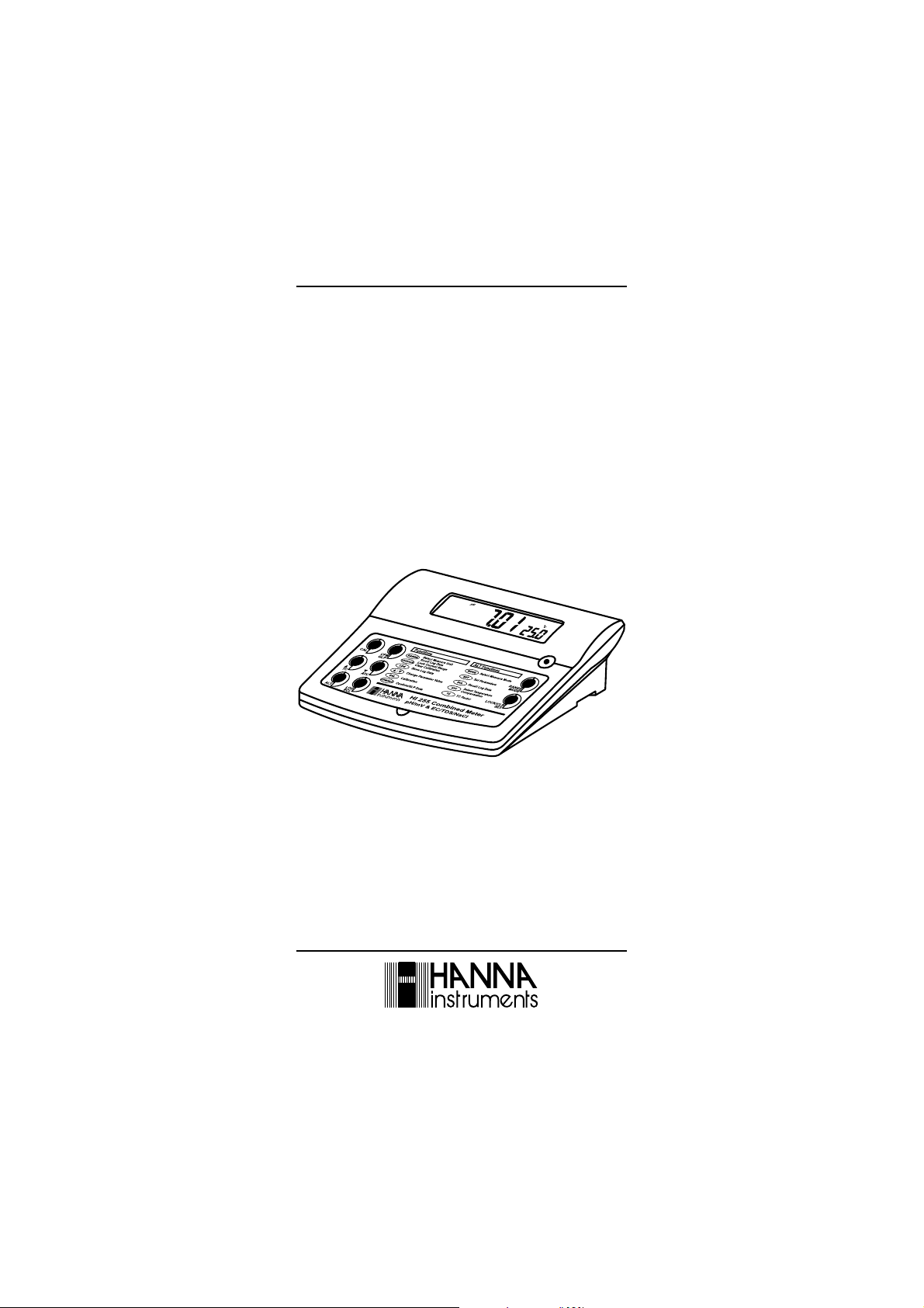
HI 255
Multiparameter
pH/mV/ºC
EC/TDS/NaCl
Bench Meter
www.hannainst.com
1
Page 2

Dear Customer,
Thank you for choosing a Hanna Instruments product.
Please read this instruction manual carefully before using the instrument.
This manual will provide you with the necessary information for correct use of
the instrument, as well as a precise idea of its versatility.
If you need additional technical information, do not hesitate to e-mail us at
tech@hannainst.com or turn to the back cover for our worldwide contact list.
WARRANTY
HI 255 is guaranteed for two years against defects in workmanship and
materials when used for its intended purpose and maintained according to
instructions. Electrodes and probes are guaranteed for six months. This
warranty is limited to repair or replacement free of charge.
Damage due to accidents, misuse, tampering or lack of prescribed maintenance
is not covered.
If service is required, contact the dealer from whom you purchased the
instrument. If under warranty, report the model number, date of purchase,
serial number and the nature of the problem. If the repair is not covered by
the warranty, you will be notified of the charges incurred. If the instrument is
to be returned to Hanna Instruments, first obtain a Returned Goods Authorization number from the Technical Service department and then send it with
shipping costs prepaid. When shipping any instrument, make sure it is
properly packed for complete protection.
TABLE OF CONTENTS
WARRANTY ................................................................................................................... 2
PRELIMINARY EXAMINATION ........................................................................................... 3
GENERAL DESCRIPTION .................................................................................................... 3
FUNCTIONAL DESCRIPTION ............................................................................................. 4
HI 255 SPECIFICATIONS .................................................................................................. 5
OPERATIONAL GUIDE ....................................................................................................... 7
AUTORANGING ................................................................................................................ 11
pH CALIBRATION ................................................................................................................ 12
RELATIVE mV CALIBRATION .......................................................................................... 15
ECS/TDS CALIBRATION ................................................................................................... 16
NaCl CALIBRATION .......................................................................................................18
GOOD LABORATORY PRACTICE (GLP) .....................................................................................19
LOGGING FUNCTION .......................................................................................................25
SETUP .................................................................................................................................31
TEMPERATURE CALIBRATION (FOR TECHNICAL PERSONNEL ONLY) .................................36
mV CALIBRATION (FOR TECHNICAL PERSONNEL ONLY) .............................................. 38
PC INTERFACE ............................................................................................................... 39
pH VALUES AT DIFFERENT TEMPERATURES .................................................................... 41
CONDUCTIVITY VERSUS TEMPERATURE CHART ................................................................ 42
ELECTRODE CONDITIONING & MAINTENANCE ................................................................. 43
TROUBLESHOOTING GUIDE ........................................................................................... 46
TEMPERATURE CORRELATION FOR pH SENSITIVE GLASS .............................................47
ACCESSORIES .................................................................................................................... 48
2
Page 3

PRELIMINARY EXAMINATION
Remove the instrument from the packing material and examine it carefully to
make sure that no damage has occurred during shipping. If there is any
damage, notify your Dealer or the nearest Hanna Customer Service Center.
Each instrument is supplied with:
HI 1131B Glass-body Combination pH Electrode with 1 m (3.3') Cable
HI 76310 Conductivity / TDS probe
HI 7662 Temperature Probe
HI 76404 Electrode Holder
pH 4.01 & 7.01 Buffer Solutions (20 mL each)
HI 7071S Electrolyte Solution
12VDC Power Adapter
Instruction Manual
Note: Save all packing material until you are sure that the instrument
functions correctly. All defective items must be returned in the original
packing with the supplied accessories.
GENERAL DESCRIPTION
The HANNA HI 255 is a logging microprocessor-based pH, ORP, Conductivity
(EC), TDS, NaCl and Temperature bench meter. Relative mV feature is also
provided.
The pH measurements are compensated for temperature effect manually or
automatically with the HI 7662 temperature probe.
pH Calibration is possible in up to three points, using five memorized buffers
(4.01, 6.86, 7.01, 9.18 and 10.01).
The autoranging feature of the EC and TDS ranges automatically sets the
instrument to the scale with the highest possible resolution.
The conductivity measurements are compensated for temperature effect manually
or automatically with the temperature sensor inside the conductivity probe. It is
also possible to disable the temperature compensation and measure the actual
conductivity.
The temperature coefficient is user selectable.
The GLP feature provides a guarantee of data consistency.
An alarm time-out is available to alert the user that too much time elapsed
since last pH calibration.
The instrument can store data in memory at the users request for later
retrieval.
3
Page 4
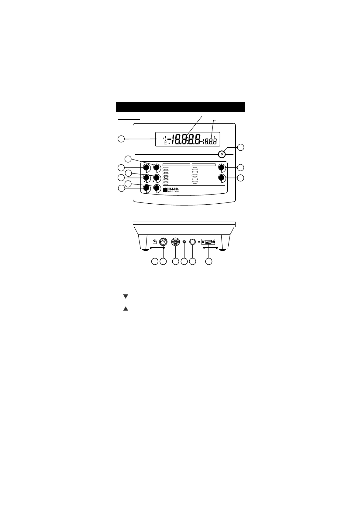
Front Panel
Primary LCD
Secondary LCD
1
9
3
2
7
4
6
5
10
8
11
13 14 15
Rear Panel
16
POWER
12VDC
INPUT TEMP
RS232
PROBE
12
ALT FunctionsFunctions
RCL
LOG
ALT
SET
LOCK/CLR
ATC
TC
MODE
RANGE
GLP
CFM
CAL
pH/mV & EC/TDS/NaCl
HI 255 Combined Meter
TC Factor
TC
ATC
Select Temperature
Compensation
Recall Log Data
RCL
SET
Set Parameters
Select Measure Mode
MODE
Confirm/GLPData
CFM/GLP
Calibration
CAL
Change Parameter Value
StoreLog Data
LOG
Lock Current Range
Clear Calibration
LOCK/CLR
Select Measure Unit
Scroll Log Data
RANGE
REF
/
BUFFER pH
INTVDATETIME%
ppm
S
3
2
1
BUF
WRONG
READY
CFM
NaCl
pHmVg / lLOGCAL
FUNCTIONAL DESCRIPTION
1) Liquid Crystal Display (LCD).
2) CFM/GLP key, to confirm different values or to display Good Laboratory
Practice information.
3) CAL key, to enter and exit/escape calibration mode.
4) key, to manually decrease temperature value or other parameters.
ATC key (alternate function), to select EC temperature compensation mode.
5) key, to manually increase temperature value or other parameters.
TC key (alternate function), to view the temperature coefficient value.
6) LOG key, to store measured data.
RCL key (alternate function), to enter/exit recall mode.
7) ALT key, to select alternate key function.
8) LOCK/CLR key, to freeze current EC range on the LCD or to clear pH
calibration parameters.
SET key (alternate function), to enter/exit setup mode.
9) RANGE key, to switch measurement unit pH/mV/EC or focused data.
MODE key (alternate function), to select measurement mode/pH resolution.
10) ON/OFF switch.
11) Power supply socket.
12) Conductivity socket.
13) BNC electrode connector.
14) Electrode reference socket.
15) Temperature probe socket.
16) RS232 serial communication connector.
4
Page 5
HI 255
EGNAR
Hp00.61ot00.2
Hp000.61ot000.2
Vm9.996±
Vm0002±
99.92ot00.0
µ mc/S
9.992ot0.03
µ mc/S
9992ot003
µ mc/S
mc/Sm99.92ot00.3
mc/Sm0.002ot0.03
lautcamc/Sm0.005otpu
)*(
ytivitcudnoc
mpp99.41ot00.0
mpp9.941ot0.51
mpp9941ot051
l/g99.41ot05.1
l/g0.001ot0.51
lautcal/g0.004otpu
)*(
SDT
)rotcaf08.0htiw(
lCaN%0.004ot0.0
)EGNARHp(Cº0.021ot0.01
)EGNARCE(Cº0.06ot0.0
NOITULOSER
Hp10.0
Hp100.0
)Vm9.996±(Vm1.0
)Vm0002±(Vm1
10.0
µ mc/S
1.0
µ mc/S
1
µ mc/S
mc/Sm10.0
mc/Sm1.0
mpp10.0
mpp1.0
mpp1
l/g10.0
l/g1.0
lCaN%1.0
Cº1.0
YCARUCCA
Fº86/Cº02@
Hp10.0±
Hp200.0±
)Vm9.996±(Vm2.0±
)Vm0002±(Vm1±
50.0(±gnidaerfo%1±
µ romc/S
)retaergrevehcihw,tigid1
rompp30.0(±gnidaerfo%1±
1 )retaergrevehcihw,tigid
gnidaerfo%1±
Cº4.0±
)rorreeborpgnidulcxe(
SPECIFICATIONS
(*)
Actual conductivity (or TDS) is the conductivity (or TDS) value without temperature compensation.
5
Page 6
egnartesffoVmleR Vm0002±
ecafretniretupmoC 232SRdetalosi-otpo
noitarbilaCHp
;noitarbilactniop3ro2,1
elbaliavasreffub5
)10.01,81.9,10.7,68.6,10.4(
noitarbilaCCE
;noitarbilacepolstniop1
:elbaliavasreffub6
3141,0.48
µ mc/S
mc/Sm8.111,0.08,88.21,00.5
:tesffotniop1
00.0
µ mc/S
noitarbilaClCaN
reffubL7307IHhtiwtniop1
)lanoitpo(
erutarepmeT
noitasnepmoc
:morfcitamotuArolaunaM
)EGNARHp(Cº0.021ot0.01
)EGNARCE(Cº0.06ot0.0
ytivitcudnocnodelbasidebnac(
)ytivitcudnoclautcaerusaemotegnar
erutarepmetytivitcudnoC
tneiciffeoc
Cº/%00.6ot00.0
)ylnoSDTdnaCErof(
Cº/%09.1sieulavtluafed
rotcafSDT
08.0ot04.0
)05.0sieulavtluafed(
edortcelEHp B1311IH
eborPCE 01367IH
eborperutarepmeT 2667IH
ecnadepmitupnI 01
21
mho
ylppusrewoP retpadaCDV21
snoisnemiD )9.2x1.7x4.9(mm47x281x042
thgieW
;)bl5.2(gK1.1
)bl5.5(gK5.2redlohhtiwtik
tnemnorivnE
)Fº22123(Cº050
gnisnednocnon%59HRxam
ytnarraW sraey2
HI 255
SPECIFICATIONS (cont.)
6
Page 7
OPERATIONAL GUIDE
POWER CONNECTION
Plug the 12 VDC adapter into the power supply socket.
Note: This instrument uses non volatile memory to retain the calibration
parameters and all other settings, even when unplugged.
Note: Make sure a fuse protects the main line.
ELECTRODE AND PROBE CONNECTIONS
For pH or ORP measurements connect an electrode with internal reference to
the BNC connector on the back of the instrument.
For electrodes with a separate reference connect the electrodes BNC to the BNC
connector and the reference electrode plug to the reference socket.
For temperature measurements and automatic temperature compensation
connect the temperature probe to the appropriate socket.
For EC/TDS measurements connect the probe to the 7-pin connector. Make sure
the probe sleeve is properly inserted.
INSTRUMENT START-UP
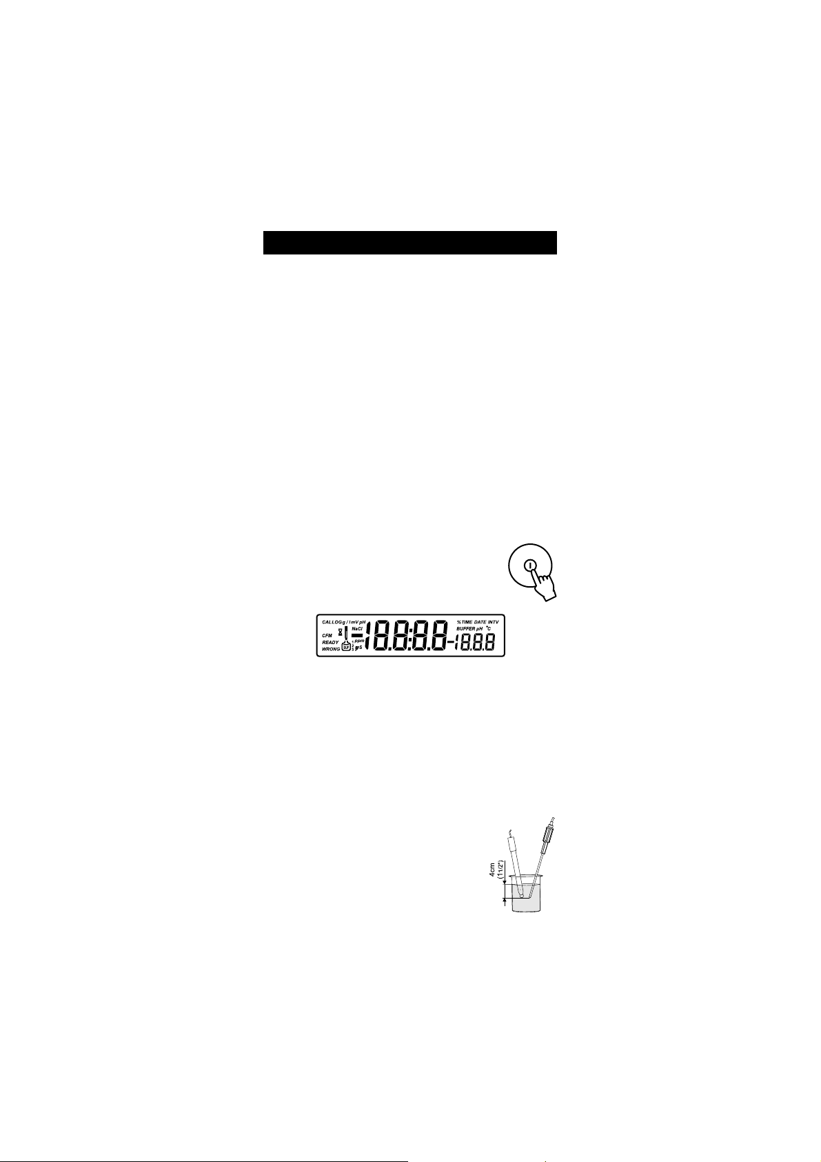
Turn the instrument on by pressing the ON/OFF switch.
All LCD tags are displayed and a beep is sounded while
the instrument performs a self test.
Note: • The instrument starts in the same range and mode as it was at
power off.
• The RANGE key toggles between pH, mV and EC ranges.
• The ALT&MODE keys changes the displayed information for the
selected range.
pH MEASUREMENTS
Make sure the instrument has been calibrated before taking
pH measurements.
Press RANGE to enter pH range.
Note: To select pH resolution press the ALT&MODE keys.
Submerge the electrode tip and the temperature probe
approximately 4 cm (1½) into the sample to be tested
and stir gently. Allow time for the electrode to stabilize.
7
Page 8
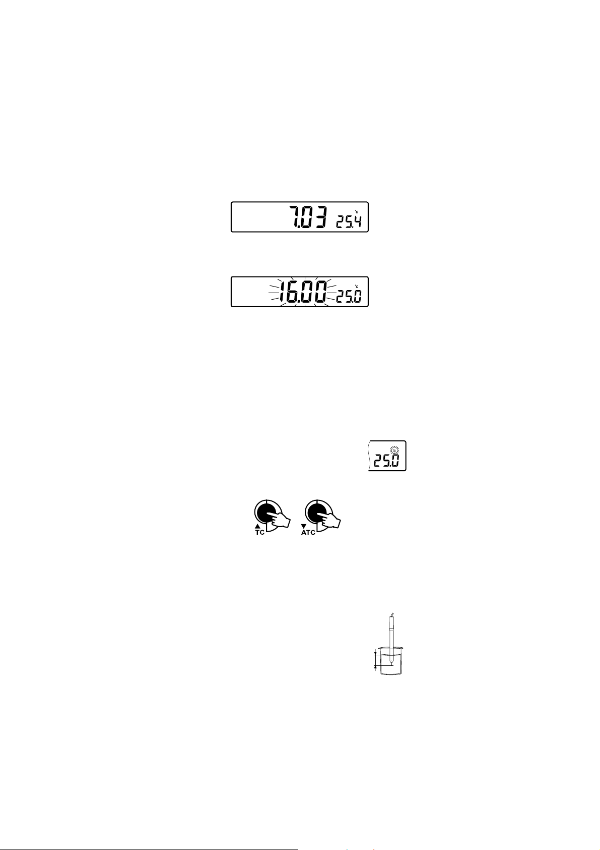
The pH is displayed on the primary LCD and the temperature on the
4cm
(1 )
1/2”
pH
pH
secondary LCD.
If the reading is out of range, the closest full-scale value will be displayed
blinking on the primary LCD.
If measurements are taken successively in different samples, it is recommended
to rinse the electrode thoroughly with deionized water or tap water and then
with some of the next sample to prevent cross-contamination.
The pH reading is affected by temperature. In order to measure the pH
accurately, the temperature effect must be compensated for. To use the
Automatic Temperature Compensation feature, connect and submerge the
HI 7662 temperature probe into the sample as close as possible to the
electrode and wait for a few seconds.
If the temperature of the sample is known, manual compensation can be
performed by disconnecting the temperature probe.
The display will then show the default temperature of 25 ºC or
the last temperature reading with the ºC tag blinking.
The temperature can now be adjusted with the ARROW keys
(from 10.0 ºC to 120.0 ºC).
mV/ORP MEASUREMENTS
An optional ORP electrode must be used to perform ORP measurements
(see Accessories).
Oxidation-Reduction Potential (REDOX) measurements provide the quantification
of the oxidizing or reducing power of the tested sample.
To correctly perform a REDOX measurement, the surface of the
ORP electrode must be clean and smooth.
Press RANGE to enter mV range.
Submerge the tip of the ORP electrode (4 cm/1½) into
the sample to be tested and allow a few seconds for the
reading to stabilize.
8
Page 9
The instrument displays the mV reading on the primary LCD and the
mV
mV
mV
temperature on the secondary LCD line.
If the reading is out of range, the closest full-scale value will be displayed
blinking on the primary LCD.
RELATIVE mV MEASUREMENTS
Press the ALT&MODE keys simultaneously while in mV range. The rEL
message will be displayed on the secondary LCD line for about one second and
the mV tag will blink. After one second the temperature will be displayed on
the secondary LCD line.
The reading displayed by the instrument is equal to the difference between
the current mV input value and relative mV offset established in the relative
mV calibration.
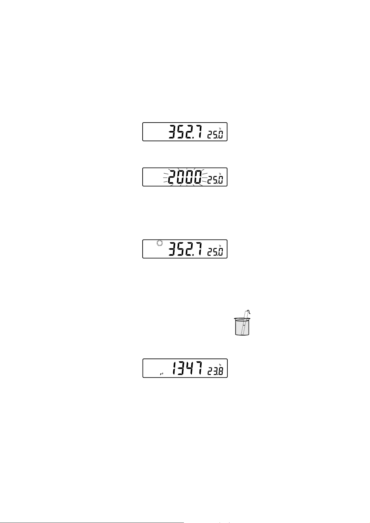
CONDUCTIVITY MEASUREMENTS
Connect the conductivity probe to the instrument.
Press RANGE to enter conductivity measurement range (EC).
Immerse the probe into the solution to be tested. The sleeve
holes must be completely submerged. Tap the probe repeatedly to
remove any air bubbles that may be trapped inside the sleeve.
The conductivity value will be displayed on the primary LCD and the
temperature on the secondary LCD line.
If the reading is out of range, the full-scale value (200.0 for Mtc/Atc mode
or 500.0 for actual conductivity) will be displayed blinking.
9
Page 10
If LOCK was pressed to freeze the LCD range and the reading went out of
ALT
ATC
range, the full-scale value of the frozen range will be displayed blinking.
The EC reading is affected by temperature.
Three options of compensating temperature are available, on EC measurement
mode.
Note: The compensation is referenced at the selected reference temperature
(see SETUP for details, page 31).
Automatic (Atc): The EC probe has a built-in temperature sensor; the
temperature value is used to automatically compensate the EC/TDS reading
(from 0.0 60.0 ºC).
Manual (Mtc): The temperature value, shown on the secondary LCD, can be
manually set with the ARROW keys. The ºC tag blinks when this option is active.
No Compensation (notc): The temperature
value is displayed, but is not taken into account
and ºC tag blinks with a higher frequency.
The reading displayed on the primary LCD is the
actual EC or TDS value. To select the desired
option, press the ALT&ATC keys until the option
is displayed on the LCD.
Note: • The default compensation mode is Atc.
• If no temperature probe detected, Atc mode can not be selected
and the instrument displays ---- on the secondary LCD.
If temperature compensation is active, measurements are compensated using the
temperature coefficient (default value 1.90 %/ºC). To change the temperature
coefficient, enter the setup mode and select the tc item (see SETUP for details,
page 31). The current temperature coefficient can be quickly viewed by pressing
the ALT&TC keys. The value is briefly displayed on the secondary LCD.
If the temperature reading is out of 0.0 60.0 ºC interval and Atc option is
selected, the ºC tag will blink and the closest interval limit will be displayed.
Press the ARROW keys to change the displayed temperature value. This
value is used to compensate the EC/TDS reading.
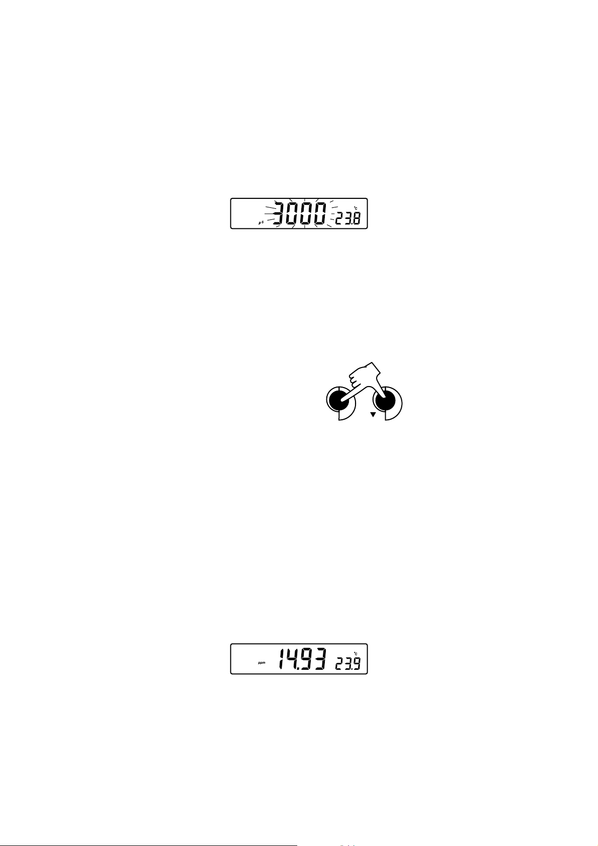
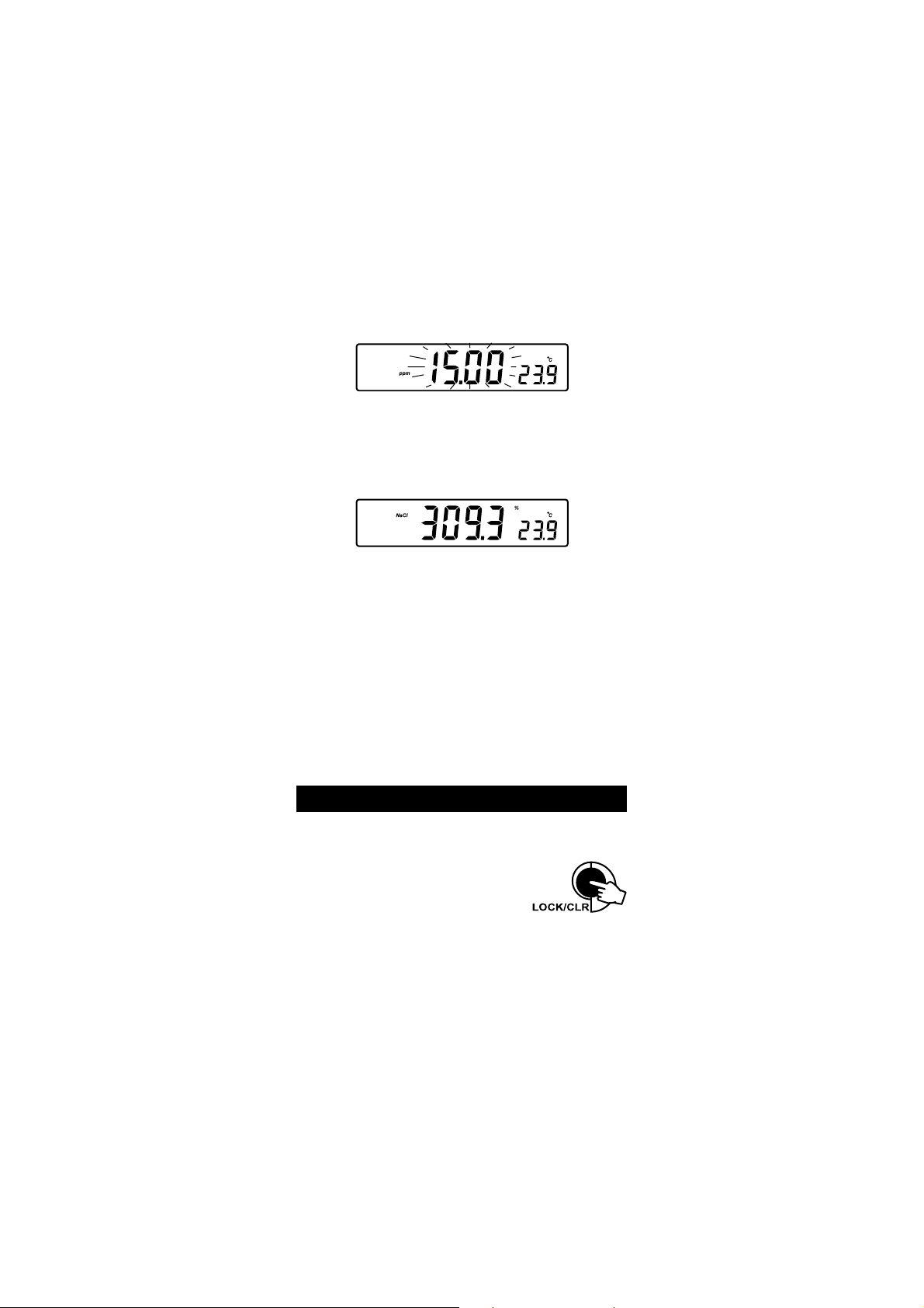
TDS MEASUREMENTS
Press the ALT&MODE keys while in EC range. The instrument will switch to TDS
measuring range. A TDS reading will be displayed on the primary LCD and the
temperature reading on the secondary LCD.
10
Page 11
If the reading is out of range, the full-scale value (100.0 for Mtc/Atc mode
or 400.0 for actual TDS) will be displayed blinking.
If LOCK was pressed to freeze the LCD range and the reading went out of
range, the full-scale value of the frozen range will be displayed blinking.
NaCl MEASUREMENTS
Press the ALT&MODE keys while in EC range until NaCl is displayed on the
LCD. The instrument will display the NaCl reading on the primary LCD and the
temperature reading on the secondary LCD line.
If the reading is out of range, the full-scale value (400.0%) will be
displayed blinking.
TEMPERATURE MEASUREMENTS
To take temperature measurements while the instrument is in pH/ORP range,
connect the HI 7662 temperature probe to the appropriate socket.
Immerse the temperature probe into the sample and allow the reading on
the secondary LCD to stabilize.
For EC/TDS/NaCl range, the HI 76310 probe has a built-in temperature sensor.
Note: If the instrument is in pH/ORP range and the HI7662 temperature
probe is not connected, the ºC tag will blink (manual compensation)
even if EC probe is connected.
AUTORANGING
The EC and TDS scales are autoranging. The meter automatically sets the scale
with the highest possible resolution.
By pressing LOCK, the autoranging feature is disabled
and the current range is frozen on the LCD. The Auto
Off (autoranging disabled) tags will be displayed on
the LCD for a few seconds. To restore the autoranging option, press LOCK
again. The Auto On (autoranging enabled) tags will be displayed on the
LCD for a few seconds.
Note: Autoranging is automatically restored if the range is changed, if the setup or
calibration modes are entered and if the meter is turned off and back on again.
11
Page 12
pH CALIBRATION
1
BUF
BUFFER pH
1
BUF
pHCAL
Calibrate the instrument frequently, especially if high accuracy is required.
The instrument should be recalibrated :
Whenever the pH electrode is replaced.
At least once a week.
After testing aggressive chemicals.
If CAL INTV tags are blinking during measurement.
Every time you calibrate the instrument use fresh buffers and perform an
electrode Cleaning Procedure (see page 45).
PREPARATION
Pour small quantities of the buffer solutions into clean beakers. If possible, use
plastic or glass beakers to minimize any EMC interferences.
For accurate calibration and to minimize cross-contamination, use two beakers
for each buffer solution. One for rinsing the electrode and one for calibration.
If you are measuring in the acidic range, use pH 7.01or 6.86 as first buffer and
pH 4.01 as second buffer. If you are measuring in the alkaline range, use pH
7.01 or 6.86 as first buffer and pH 10.01 or 9.18 as second buffer.
PROCEDURE
Calibration has a choice of 5 memorized buffers: pH 4.01, 6.86, 7.01, 9.18
and 10.01.
It is recommended to perform a two or three-point calibration. However, the
instrument also allows a one-point calibration, as described on page 14.
Select pH range by pressing RANGE.
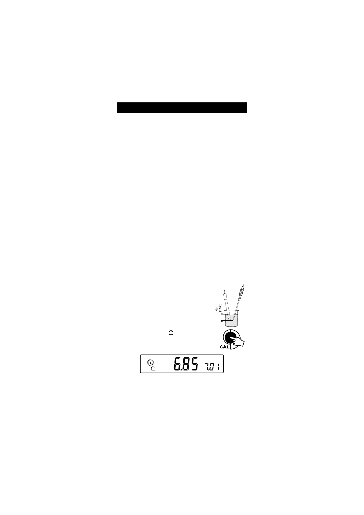
THREE-POINT CALIBRATION
Immerse the pH electrode and the temperature probe
approximately 4 cm (1½) into a buffer solution of
your choice (pH 4.01, 6.86, 7.01, 9.18 or 10.01)
and stir gently. The temperature probe should be
close to the pH electrode.
Press CAL. The CAL and
the 7.01 buffer will be displayed on the secondary
LCD.
tags will appear and
If necessary, press the ARROW keys to select a different buffer value.
12
Page 13
The tag will blink on the LCD until the reading is
BUFFER pH
2
BUF
pHCAL
stable.
When the reading is stable and close to the selected buffer,
READY tag will be displayed and CFM tag will blink.
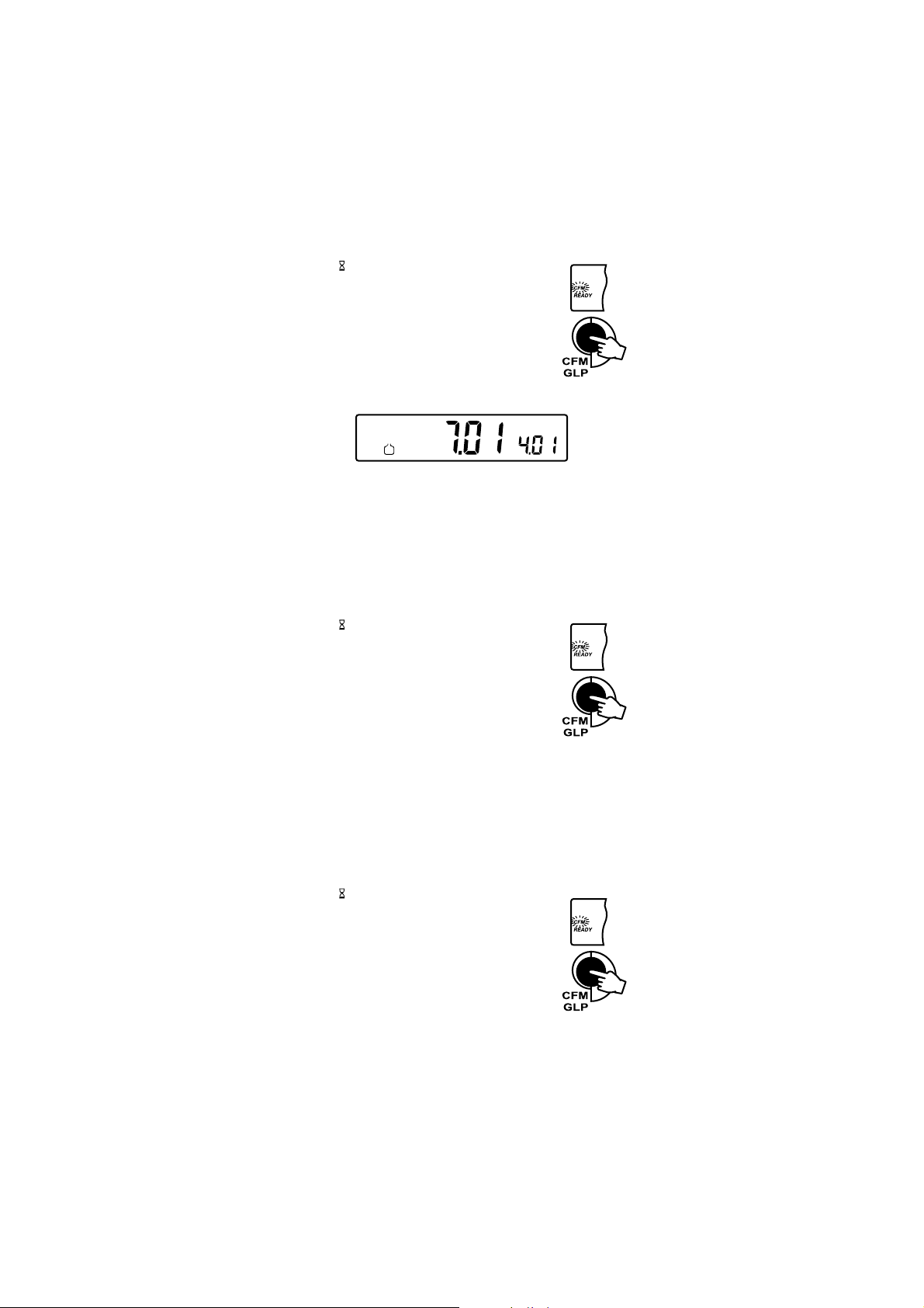
Press CFM to confirm calibration.
The calibrated value will be displayed on the primary LCD
and the second expected buffer value on the secondary
LCD line.
Note: The instrument will automatically skip the buffer used for the first point.
It also skips 6.86 if 7.01 buffer was used and viceversa. Likewise, it will
skip 9.18 if 10.01 buffer was used and viceversa.
After the first calibration point is confirmed, immerse the pH electrode and
the temperature probe approximately 4 cm (1½) into the second buffer
solution and stir gently. The temperature probe should be close to the pH
electrode.
If necessary, press the ARROW keys to select a different buffer value.
The tag will blink on the LCD until the reading is
stable.
When the reading is stable and close to the selected buffer,
READY tag will be displayed and CFM tag will blink.
• Press CFM to confirm calibration.
• The calibrated value will be displayed on the primary LCD
and the third expected buffer value on the secondary LCD
line.
Note: The instrument will automatically skip the buffer used for the first and
second calibration point.
After the second calibration point is confirmed, immerse the pH electrode
and the temperature probe approximately 4 cm (1½) into the third
buffer solution and stir gently. The temperature probe should be close to
the pH electrode.
If necessary, press the ARROW keys to select a different buffer value.
The tag will blink on the LCD until the reading is
stable.
When the reading is stable and close to the selected buffer,
READY tag will be displayed and CFM tag will blink.
• Press CFM to confirm calibration.
The instrument stores the calibration value and returns
to normal measurement mode.
13
Page 14
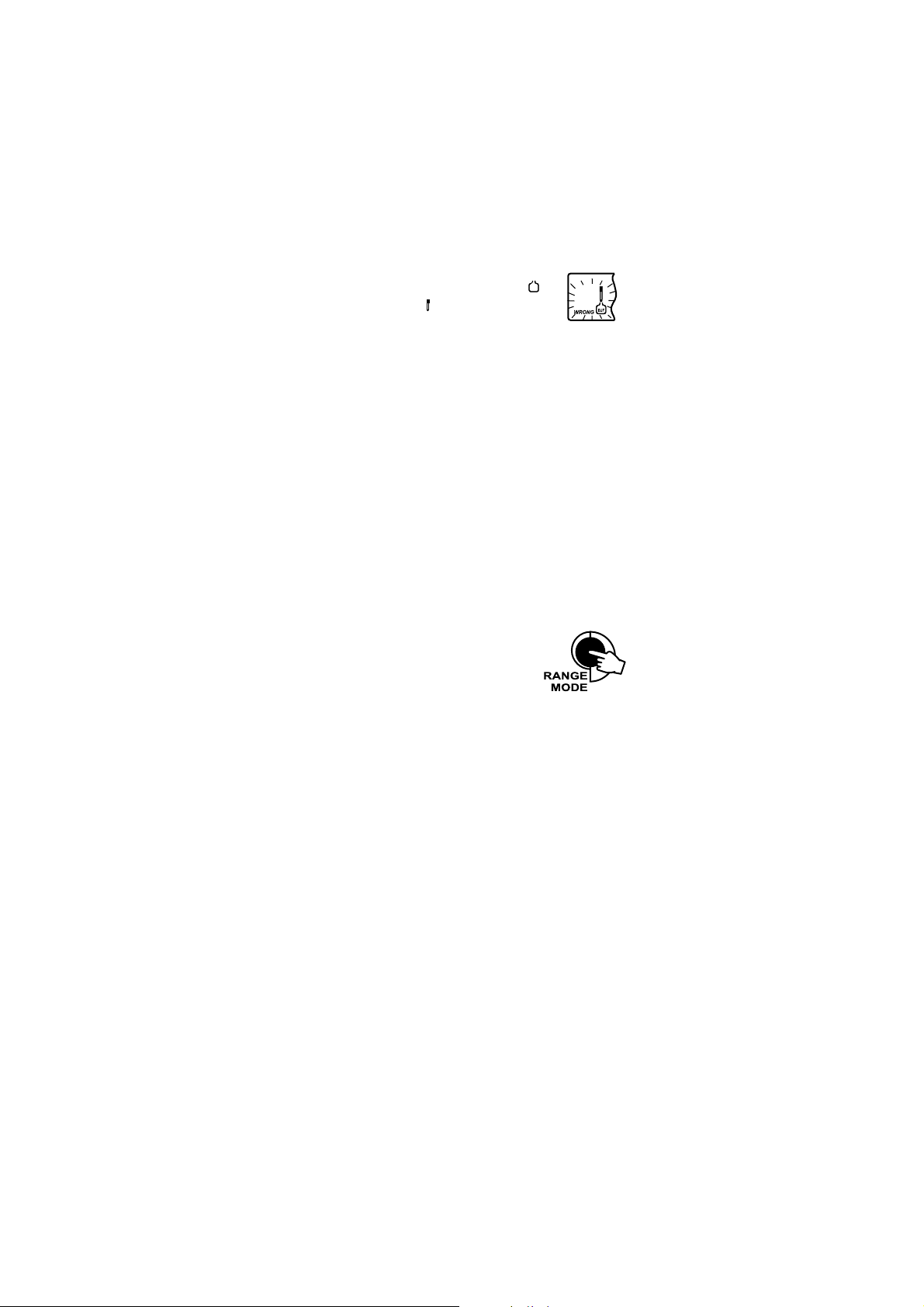
Note: If the value measured by the instrument is not
2
BUF
close to the selected buffer, WRONG
and WRONG tags will blink alternately.
In this case, check if the correct buffer has been
used or regenerate the electrode by following the Cleaning Procedure (see page 45). If necessary, change the buffer or the
electrode.
If WRONG, Buffer pH tags and Old tag on secondary LCD are
displayed blinking, an inconsistency between new and previous
(old) calibration is detected. Clear calibration parameters by
pressing LOCK/CLR and proceed with calibration from the
current calibration point (the instrument will keep all confirmed
values during current calibration).
If LOCK/CLR is pressed at the first calibration point, the instru-
ment clears all calibration parameters and returns to measurement
mode.
The WRONG tag and temperature value are displayed blinking
if temperature reading is out of the defined temperature range of
the buffer. Calibration cannot be confirmed in this situation.
Press RANGE to display the temperature reading
on the LCD during calibration.
TWO-POINT CALIBRATION
Proceed as described in Three-point calibration section.
Press CAL after the second calibration point was confirmed.
The instrument will return to measurement mode and will memorize the
two-point calibration data.
ONE-POINT CALIBRATION
Proceed as described in Three-point calibration section.
Press CAL after the first calibration point was confirmed.
The instrument will return to measurement mode and will memorize the
one-point calibration data.
Note: Calibration parameters are evaluated taking in consideration the new
values for the confirmed buffers in current calibration and the old
values, if existing, for the other buffers. To clear old calibration values,
press LOCK/CLR before exiting calibration.
14
Page 15

RELATIVE mV CALIBRATION
Press CAL when the instrument is in RELATIVE mV measurement mode.
The mV and tags will blink. Absolute mV is displayed on the
primary LCD and AbS message is displayed on the secondary LCD.
When the reading is stable and inside the offset window (±200 0 mV), the
instrument asks for confirmation.
If the reading is out of the offset window, WRONG tag will be displayed.
Press CFM to confirm absolute value. The instrument will display 0.0 mV
on the primary LCD and rEL message on the secondary LCD line. In this
moment the relative mV offset is equal to absolute mV reading.
Use the ARROW keys if you want to change the displayed value.
Press CFM to confirm relative mV calibration. The instrument will return to
measurement mode.
15
Page 16
EC/TDS CALIBRATION
S
BUF
CAL
S
BUF
CAL
READY
CFM
EC calibration is a one-point procedure. Selectable calibration points are 0.00 µS
for offset and 84.0 µS, 1413 µS, 5.00 mS, 12.88 mS, 80.0 mS, 111.8 mS for
slope.
Rinse the probe with calibration solution or deionized water.
Immerse the probe into the solution. The sleeve holes must be
completely submerged. Tap the probe repeatedly to remove
any air bubbles that may be trapped inside the sleeve.
To enter EC calibration, select the EC range and press CAL.
Note: TDS reading is automatically derived from the EC
reading and no specific calibration for TDS is needed.
Pressing CAL when TDS range is selected has no
effect.
For zero calibration, just leave the dry probe in the air. This calibration is
performed in order to correct the reading around 0.00 µS point. The slope is
evaluated when the calibration is performed in any other point.
The BUF and CAL tags are displayed. The primary LCD will display the EC
reading. The secondary LCD will display the buffer value. The and ~
tags will blink.
Select the desired value with the ARROW keys, if necessary.
When the reading is stable, READY tag is displayed and CFM tag starts
blinking on the LCD, asking for confirmation.
Press CFM to confirm calibration.
The instrument stores the calibration value and returns to
measurement mode.
Note: • If the uncalibrated reading is too far from the expected value, the
WRONG and tags will blink. Calibration can not be confirmed.
In this case check if the correct buffer has been used or clean the probe
by following the Cleaning Procedure (see page 45).
16
Page 17
• If the meter is in Atc mode and the buffer temperature is out of
WRONG
CAL
0.0 60.0 ºC interval, WRONG ºC tags and the temperature
will be displayed blinking.
• For best results choose an EC buffer value close to the sample to be
measured.
• In order to minimize any EMC interference, use plastic or glass
beakers.
• It is possible to set the cell constant value directly, without following
the calibration procedure. To set the cell constant, enter SETUP
mode and select CEL (see SETUP for details, page 31).
17
Page 18

NaCl CALIBRATION
BUF
CAL
%
NaCl
%
BUF
READY
CFM
CAL
NaCl
NaCl calibration is a one-point procedure at 100.0% NaCl. Use the HI7037L
calibration solution (sea water solution) as a 100% NaCl standard solution.
Rinse the probe with some of the calibration solution or
deionized water. Immerse the probe into HI 7037L solution.
The sleeve holes must be completely submerged. Tap the
probe repeatedly to remove any air bubbles that may be
trapped inside the sleeve.
To enter NaCl calibration select the NaCl range and
press CAL.
The BUF and CAL tags are displayed. The primary LCD will display the
NaCl reading in percentage. The secondary LCD will display 100. The
and ~ tags will blink.
When the reading is stable, the READY tag will be displayed and CFM tag
starts blinking on the LCD, asking for confirmation.
Press CFM to confirm calibration.
The instrument stores the calibration value and returns to
measurement mode.
Note: • If the reading is too far from the expected value, WRONG
tags will blink. Calibration cannot be confirmed.
• If the temperature of the buffer is out of 0.0 60.0 ºC temperature
interval, the WRONG and ºC tags will be displayed blinking.
• If a new EC calibration is performed, NaCl calibration is auto-
matically cleared. Thus, a new NaCl calibration is required.
18
Page 19

GOOD LABORATORY PRACTICE (GLP)
DATE
CAL
mVCAL
GLP is a set of functions that allows storage and retrieval of data regarding the
maintenance and status of the electrode.
All data regarding pH, Rel mV, EC and NaCl is stored for the user to review
when necessary.
CALIBRATION ALARM TIME-OUT
For pH calibration, this instrument allows the user to set the number of days
before the next required pH calibration. This value can be set from 1 to 7 days.
The default setting is OFF (disabled).
The instrument checks if the time-out time has expired. If the time elapsed, the
CAL INTV tags will blink as a reminder.
Note: If the instrument was not calibrated, the CAL INTV tags will be
displayed even if the feature is disabled in SETUP menu.
LAST pH CALIBRATION DATA
The last pH calibration data is stored automatically after a successful calibration.
To view the pH calibration data, press GLP when the instrument is in pH (mV)
measurement mode.
The instrument will display the time (hh:mm) of the last calibration.
Press the ARROW keys to view the next logged calibration parameter
(pressing the key):
The date (yy.mm.dd).
The pH calibration offset.
19
Page 20

The pH calibration slope(the GLP slope is the average of the calibration
BUF
pHCAL
BUF
pHCAL
BUF
CAL
BUF
pHCAL
%
CAL
CAL
CAL
slopes; the percentage is referred to the ideal value of 59.16 mV/pH).
The calibration buffers in calibrating order.
The first pH calibration buffer:
The second pH calibration buffer:
The third pH calibration buffer:
Note: The OLd message displayed beside the pH value means that this
buffer was not used during last calibration. Press and hold down
the ALT&SET keys if you want to see calibration date (or time if old
calibration was made in the same day with current calibration).
If no bUF message appears on the LCD, the instrument informs
you that calibration was performed in less than three points.
Temperature compensation mode (Atc or Mtc; with or without temperature
probe).
pH resolution during calibration:
20
Page 21

INTV
CAL
TIME
CAL
DATE
CAL
Calibration Alarm Time-Out status:
if disabled.
or the number of days until the calibration alarm will be displayed.
or if expired (7 days ago).
The instrument ID.
LAST Relative mV CALIBRATION DATA
Last Relative mV calibration data is stored automatically after a successful
calibration.
To view the Relative mV calibration data, press GLP when the instrument is
in Relative mV measurement mode.
The instrument will display the time (hh:mm) of the last calibration.
Press the ARROW keys to view the next logged calibration parameter
(pressing the key):
The date (yy:mm:dd):
21
Page 22

The Relative mV calibration offset:
DATE
CAL
The instrument ID.
LAST EC CALIBRATION DATA
Last EC calibration data is stored automatically after a successful calibration.
To view the EC calibration data, press GLP when the instrument is in EC
measurement mode.
The instrument will display:
The time.
Press the ARROW key to view the next logged calibration parameters
(pressing the key).
The date.
The EC calibration buffer.
The cell constant.
The calibration offset factor.
22
Page 23

The reference temperature.
DATE
CAL
The temperature coefficient.
The temperature compensation mode.
The instrument ID.
LAST NaCl CALIBRATION DATA
Last NaCl calibration data is stored automatically after a successful calibration.
To view the NaCl calibration data, press GLP when the instrument is in NaCl
measurement mode. The instrument will display:
The time.
Press the ARROW key to view the next logged calibration parameters
(pressing the key).
The date.
The salinity coefficient.
23
Page 24

The cell constant.
CAL
The reference temperature.
The temperature compensation mode.
The instrument ID.
Note: If notc is selected as temperature compensation mode during
calibration, the temperature coefficient is not displayed in GLP.
Press GLP at any moment and the instrument will return to
measurement mode.
If calibration has not been performed on the selected range, the
instrument displays no CAL message blinking.
24
Page 25

LOGGING FUNCTION
LOG
LOG
LOG
LOG
LOG
Up to 200 LOG samples can be stored into memory.
LOGGING THE CURRENT DATA
To store the current reading into memory press LOG while the instrument is in
measurement mode.
The instrument will display the current date (mm.dd) on the primary LCD, the
record number on the secondary LCD and LOG tag will blink for a few seconds
(see example below: record No. 5 dated September 14):
If there are less than 6 memory locations remaining, the record number and
Lo message will blink to alert the user.
If the log space is full, FULL LOC message will be displayed and no more
data will be saved.
When LOG is pressed, a complete set of information of the corresponding measurement range is stored.
VIEW LOGGED DATA
Press the ALT&RCL keys while in measurement mode to retrieve the stored
information.
If no data were logged, the instrument displays:
If no data were logged for the current selected measurement range, one of the
next messages will be displayed:
On pH measurements ranges:
25
Page 26

On Relative mV range:
LOG mV
LOG
LOG
LOG
pHLOG
On EC range:
On TDS range:
On NaCl range:
Otherwise, the instrument will display the memorized data:
If RCL is invoked while the instrument is in pH or mV measurement range:
Or if RCL is invoked while the instrument is in Rel mV range:
Or if RCL is invoked while the instrument is in EC measurement range:
Or if RCL is invoked while the instrument is in TDS measurement range:
26
Page 27

Or if RCL is invoked while the instrument is in NaCl measurement range:
pHLOG
pHLOG
LOG
LOG mV
Pressing the ARROW keys, the instrument will display the same parameter
but for a different record:
(example on pH range)
or
Note: The instrument will automatically skip log records from other measure-
ment ranges.
Press RANGE and the instrument will display the next logged parameter as
follows:
For pH/mV Range
The temperature value on the primary LCD and the record number on
the secondary LCD.
The mV value on the primary LCD and the record number on the secondary LCD.
Note: When the pH, mV or temperature is displayed, if the ALT&SET keys
are pressed and hold down, the secondary LCD will display the record
date.
27
Page 28

The time on the primary LCD, along with TIME tag.
CFM
LOG
CFM
LOG
TIME
LOG
DATE
LOG
mVLOG
%
LOG
The date on the primary LCD, along with DATE tag.
The calibration offset on the primary LCD and OFS message on the
secondary LCD.
The calibration slope on the primary LCD and SLP message on the
secondary LCD.
The temperature compensation mode on the primary LCD and tcP
message on the secondary LCD.
Note: When the time, date, year, offset or slope is displayed, if the ALT&SET
keys are pressed and hold down, the secondary LCD will display the
record number.
The dEL message on the primary LCD and the selected record on the
secondary LCD, with LOG tag displayed and CFM tag blinking.
Note: If one of the ARROW keys is pressed while dEL and record
number is displayed, the next/previous record number is selected.
If the ALT&SET keys are pressed, the secondary LCD will display
ALL message.
28
Page 29

Pressing the ALT&SET keys again, the secondary LCD will display
mVLOG
the record number.
Press CFM to confirm deletion.
If dEL ALL option was selected, all records (for all ranges) are
deleted and the instrument returns to measurement mode.
For Relative mV Range
The temperature value, the mV absolute value, the time and the date as
described above.
The Relative mV offset.
The dEL message as described above.
For EC Range
The temperature value, time and date as described on pH Range.
The offset factor on the primary LCD and OFS message on the
secondary LCD.
The reference temperature on the primary LCD and rEF message on
the secondary LCD.
The temperature coefficient on the primary LCD and tc message on
the secondary LCD.
The temperature compensation mode as described on pH Range.
The cell constant on the primary LCD and CEL message on the secondary
LCD line.
Note: When the EC or temperature is displayed, if the ALT&SET keys
are pressed and hold down, the secondary LCD will display the
record date.
29
Page 30

When the information that does not display the record number is
NaCl
LOG
selected, pressing and keeping hold down the ALT&SET keys will
display the record number on the secondary LCD line.
The dEL message as described in pH Range.
For TDS Range
The temperature reading as described in pH range (page 27).
The conductivity value on the primary LCD and the record number on the
secondary LCD.
The time and the date as described in pH Range.
The TDS factor on the primary LCD and cF message on the secondary LCD.
The reference temperature, the temperature coefficient, the temperature
compensation mode and the cell constant as described in EC Range.
The dEL message as described in pH Range.
For NaCl Range
The temperature reading as described in pH Range (page 27).
The conductivity value as described in TDS Range.
The time and date as described in pH Range.
The salinity factor on the primary LCD and cF message on the secondary
LCD, with LOG and NaCl tags displayed.
The reference temperature, the temperature compensation mode, the cell
constant and dEL message as described above.
Note: After LOG is pressed or dEL is confirmed, the instrument will
display the amount of free log space for about one second (example
25 records free).
Press the ALT&RCL keys to leave RECALL mode at any time.
30
Page 31

SETUP
Setup mode allows viewing and modifying the instrument parameters.
In according with the selected range, SETUP menu allows the possibility to
view and/or change specific range parameters and common parameters (for
all ranges).
The common parameters are:
Instrument ID
Time
Date
Beep Status
Baud Rate (serial communication)
Command Prefix (serial communication)
The range specific parameters are:
In pH Range
• Calibration Alarm Time-Out
In EC/TDS/NaCl Range
• Cell Constant
• TDS Factor
• Temperature Coefficient
• Reference Temperature
To enter SETUP mode press the ALT&SET keys while the instrument is in
measurement mode. The instrument will display the first parameter of the
specific range.
Select a parameter with the ARROW keys.
Press CAL if you want to change a parameter value. The selected parameter
will start blinking.
Press RANGE to toggle between displayed parameters.
Press the ARROW keys to increase or decrease the displayed value.
Press CFM to save the modified value or CAL to escape.
Press the ARROW keys to select the next/previous parameter.
31
Page 32

SET COMMON PARAMETERS
TIME
TIME
DATE
Instrument ID parameter
Press CAL when the instrument ID is displayed. The instrument ID (0000 to
9999) will start blinking.
Press the ARROW keys to change the instrument ID value.
Press CFM to save the modified instrument ID value.
Press CAL to escape without saving.
Note: The instrument ID is downloaded to a PC as part of a logged data, set
to identify its origin.
Current Time Set
Press CAL when the current time is displayed. The hour will start blinking.
Press the ARROW keys to change the hour.
Press RANGE. The minutes will start blinking.
Press the ARROW keys to change the minutes.
Press CFM to save the modified value.
Press CAL to escape without saving.
Current Date Set
Press CAL when the current date is displayed. The year will start blinking.
Press the ARROW keys to change the year.
32
Page 33

Press RANGE. The month will start blinking.
DATE
DATE
Press the ARROW keys to change the month.
Press RANGE. The day will start blinking.
Press the ARROW keys to change the day.
Press CFM to save the modified value.
Press CAL to escape without saving.
Beep Status Set
Press CAL when the beep status is displayed. Beep status (On or OFF) will
start blinking.
Press the ARROW keys to change the beep status (On or OFF).
Press CFM to save the modified beep status.
Press CAL to escape without saving.
Note: If enabled, an audible signal will follow each key pressed. Inactive
keys have a longer beep. A longer beep can be also heard when the
range limits of a parameter are reached.
During calibration an audible signal can be heard when the
reading becomes stable.
Baud Rate Set
Press CAL when the baud rate is displayed. The baud rate (600, 1200, 2400,
4800 or 9600) will start blinking.
Press the ARROW keys to change the baud rate value.
Press CFM to save the modified baud rate value.
Press CAL to escape without saving.
33
Page 34
Serial Communication Command Prefix Set
INTV
CAL
Press CAL when the command prefix is displayed. Command prefix (0 to 47) will
start blinking.
Press the ARROW keys to change the command prefix.
Press CFM to save the modified command prefix value.
Press CAL to escape without saving.
Note: See the PC interface section on page 39 for a complete explanation.
The command prefix must be 16 if HI 92000 PC software is used.
SPECIFIC RANGE PARAMETER
pH Range
Calibration Alarm Time-Out Set
Press CAL when the calibration time-out is displayed. Calibration time-out
(OFF or 1 to 7 days) will start blinking.
.
Press the ARROW keys to change the calibration time-out value.
Press CFM to save the modified calibration time-out value.
Press CAL to escape without saving.
EC/TDS/NaCl Range
Cell Constant Parameter Set
Press CAL when the cell constant is displayed. The cell constant will start
blinking.
Press the ARROW keys to change the cell constant (0.500 to 1.700).
Press CFM to save the modified cell constant.
Press CAL to escape without saving.
34
Page 35

TDS Factor Set
Press CAL when the TDS factor is displayed. The TDS factor will start
blinking.
Press the ARROW keys to change the TDS factor (0.40 to 0.80).
Press CFM to save the modified TDS factor.
Press CAL to escape without saving.
Temperature Compensation Coefficient Set
Press CAL when the temperature compensation coefficient is displayed. The
temperature compensation coefficient will start blinking.
Press the ARROW keys to change the temperature compensation coefficient.
(0.00 to 6.00 %/ºC).
Press CFM to save the modified temperature compensation coefficient.
Press CAL to escape without saving.
Reference Temperature Parameter Set
Press CAL when the reference temperature is displayed. The reference
temperature will start blinking.
Press the ARROW keys to toggle between 20.0 ºC and 25.0 ºC reference
temperature value.
Press CFM to save the modified reference temperature value.
Press CAL to escape without saving.
35
Page 36

TEMPERATURE CALIBRATION
CAL
GLP
CFM
CAL
(for technical personnel only)
The instrument has two temperature channels: one that measures the temperature from the HI 7662 probe while the instrument is in pH/mV range and
the other that measures temperature from the EC probe while the instrument
is in EC/TDS/NaCl range.
All the instruments are factory calibrated for temperature on both channels.
Hannas temperature probes are interchangeable and no temperature
calibration is needed when they are replaced.
If the temperature measurements are inaccurate, temperature recalibration
should be performed.
For an accurate recalibration, contact your dealer or the nearest Hanna
Customer Service Center, or follow the instructions bellow.
Prepare a vessel containing ice and water and another one containing hot
water (at a temperature of around 50 ºC). Place insulation material
around the vessels to minimize temperature changes.
Use a calibrated thermometer with a resolution of 0.1 ºC as a reference
thermometer. Connect the HI 7662 probe to the appropriate socket for the
pH temperature channel or the HI 76310 probe for the EC temperature
channel.
With the instrument off, press and hold down the CAL&ALT keys, then
power on the instrument to calibrate the pH temperature channel or
CAL and keys and then power on the instrument to calibrate the
EC temperature channel. The CAL tag will appear and the secondary
LCD will show 0.0 ºC.
Immerse the temperature probe (or EC probe) in the vessel with ice and
water as near as possible to the calibrated thermometer. Allow a few
seconds for the probe to stabilize.
Use the ARROW keys to set the reading on the secondary LCD to that of
ice and water, measured by the calibrated thermometer. When the
reading is stable and close to the selected calibration point, READY tag
will appear and CFM tag will blink.
Press CFM to confirm. The secondary LCD will show 50.0 ºC.
36
Page 37

Immerse the temperature probe (or EC probe) in the second vessel as near
as possible to the calibrated thermometer. Allow a few seconds for the
probe to stabilize.
Use the ARROW keys to set the reading on the secondary LCD to that of
the hot water.
When the reading is stable and close to the selected
calibration point, READY tag will appear and CFM
tag will blink.
Press CFM to confirm. The instrument returns to
measurement mode.
Note: If the reading is not close to the selected calibration point, WRONG
tag will blink. Change the temperature probe (or EC probe) and restart
calibration.
37
Page 38

mV CALIBRATION
(for technical personnel only)
All the instruments are factory calibrated for mV.
Hannas ORP electrodes are interchangeable and no mV calibration is
needed when they are replaced.
If the mV measurements are inaccurate, mV recalibration should be performed.
For an accurate recalibration, contact your dealer or the nearest Hanna
Customer Service Center or follow the instructions below.
A two or three-point calibration can be performed at 0.0 mV, 600.0 mV and
1800.0 mV.
Attach to the BNC connector a mV simulator with an accuracy of ±0.1 mV.
With the instrument off, press and hold down the CFM&LOG keys, then
power on the instrument. The CAL tag will appear and the secondary
LCD will show 0.0 mV.
Set 0.0 mV on the simulator.
When the reading is stable and close to the selected calibration point,
READY tag will appear and CFM tag will blink.
Press CFM to confirm. The secondary LCD will display 600 mV.
Set 600.0 mV on the simulator.
When the reading is stable and close to the selected calibration point,
READY tag will appear and CFM tag will blink.
Press CFM to confirm. The secondary LCD will display 1800 mV.
Set 1800.0 mV on the simulator.
When the reading is stable and close to the selected calibration point,
READY tag will appear and CFM tag will blink.
Press CFM to confirm. The instrument returns to measurement mode.
Note: If the reading is not close to the selected calibration point,
WRONG tag will blink. Verify calibration condition or contact
your vendor if you can not calibrate.
Press CAL in any moment of the calibration process. The instrument
will return to measurement mode. If calibration process is stopped
after 600 mV is confirmed, the 600 mV range is calibrated and
calibration parameters are memorized.
38
Page 39

PC INTERFACE
Data transmission from the instrument to the PC can be done with the
HI 92000 Windows® compatible software (optional). HI 92000 also offers
graphing and on-line help feature.
Data can be exported to the most popular spreadsheet programs for further
analysis.
To connect your instrument to a PC, use the optional Hanna HI 920010 cable
connector. Make sure that your instrument is switched off and plug one
connector to the instrument RS232C socket and the other to the serial port of
your PC.
Note: Other cables than HI 920010 may use a different configuration.
In this case communication between instrument and PC may not
be possible.
If you are not using Hanna Instruments HI 92000 software,
please see the following instructions.
SENDING COMMANDS FROM PC
It is also possible to remotely control the instrument with any terminal
program. Use HI 920010 cable to connect the instrument to a PC, start the
terminal program and set the communication options as follows: 8, N, 1, no
flow control.
COMMAND TYPES
To send a command to the instrument the scheme is:
<command prefix> <command> <CR>
where: <command prefix> is a selectable ASCII character
between 0 and 47.
<command> is the command code (3 characters).
Note: Either small or capital letters can be used.
SIMPLE COMMANDS
RNG Is equivalent to pressing RANGE
CAL Is equivalent to pressing CAL
CFM Is equivalent to pressing CFM/GLP
UPC Is equivalent to pressing the UP arrow key
DWC Is equivalent to pressing the DOWN arrow key
SET Is equivalent to pressing SET/CLR
LOG Is equivalent to pressing LOG
MMD Is equivalent to pressing MODE
CHR n Change the instrument range according with the parameter
value (n):
n=0 pH range/0.01 resolution
39
Page 40

n=1 pH range/0.1 resolution
n=2 mV range
n=3 Relative mV range
n=4 EC range
n=5 TDS range
n=6 NaCl range
The instrument sends the ACK (6) character every time a command is
recognized and a NAK (21) character for invalid commands.
COMMANDS REQUIRING AN ANSWER
RAS Causes the instrument to send a complete set of readings in
according with the current range:
pH, mV and temperature reading on pH range.
mV and temperature reading on mV range.
Rel mV, absolute mV and temperature reading on Rel
mV range.
Conductivity and temperature reading on EC range.
TDS and temperature reading on TDS range.
NaCl and temperature reading on NaCl range.
MDR Requests the instrument model name and firmware code.
PAR Requests the setup parameters setting.
NSL Requests the number of logged samples.
GLP Requests the calibration data record.
LOD xxx Requests the xxxth record logged data (Err3 sent when xxx is
an invalid record number).
LOD ALL Requests all logged data.
Note: Err8 is sent if instrument is not in measurement mode.
Err7 is sent if mV are asked during pH calibration mode.
NAK (21) character is sent when the instrument receives an
unknown or a corrupted command.
The characters sent by the instrument are always capital letters.
40
Page 41

pH VALUES AT DIFFERENT
PMET SEULAVHp
Cº Fº 10.4 68.6 10.7 81.9 10.01
0 23 10.4 89.6 31.7 64.9 23.01
5 14 00.4 59.6 01.7 93.9 42.01
01 05 00.4 29.6 70.7 33.9 81.01
51 95 00.4 09.6 40.7 72.9 21.01
02 86 00.4 88.6 30.7 22.9 60.01
52 77 10.4 68.6 10.7 81.9 10.01
03 68 20.4 58.6 00.7 41.9 69.9
53 59 30.4 48.6 99.6 01.9 29.9
04 401 40.4 48.6 89.6 70.9 89.9
54 311 50.4 38.6 89.6 40.9 58.9
05 221 60.4 38.6 89.6 10.9 28.9
55 131 70.4 48.6 89.6 99.8 97.9
06 041 90.4 48.6 89.6 79.8 77.9
56 941 11.4 58.6 99.6 59.8 67.9
07 851 21.4 58.6 99.6 39.8 57.9
TEMPERATURES
The temperature has an effect on pH. The calibration buffer solutions are
affected by temperature changes to a lesser degree than normal solutions.
During calibration the instrument will automatically calibrate to the pH value
corresponding to the measured or set temperature.
During calibration the instrument will display the pH buffer value at 25 ºC.
41
Page 42

CONDUCTIVITY VERSUS
Cº Fº
0307IH
0308IH
(
µ )mc/S
1307IH
1308IH
(
µ )mc/S
3307IH
3308IH
(
µ )mc/S
4307IH
4308IH
(
µ )mc/S
5307IH
5308IH
(
µ )mc/S
9307IH
9308IH
(
µ )mc/S
0 23 0517 677 46 00384 00456 0672
5 14 0228 698 56 00535 00147 0813
01 05 0339 0201 76 00695 00238 5163
51 95 08401 7411 86 00456 00529 3604
61 8.06 02701 3711 07 00276 00449 5514
71 6.26 05901 9911 17 00586 00369 5424
81 4.46 09111 5221 37 00896 00289 7334
91 2.66 03411 1521 47 00317 002001 9244
02 86 07611 8721 67 00427 001201 3254
12 8.96 01911 5031 87 00047 000401 7164
22 6.17 05121 2331 97 00257 009501 1174
32 4.37 09321 9531 18 00567 009701 5084
42 2.57 04621 6831 28 00387 008901 2094
52 77 08821 3141 48 00008 008111 0005
62 8.87 03131 0441 68 00318 008311 6905
72 6.08 07331 7641 78 00038 007511 0915
82 4.28 02631 4941 98 00948 007711 6825
92 2.48 07831 1251 09 00368 007911 3835
03 68 02141 8451 29 00288 008121 9745
13 8.78 07341 5751 49 00009 009321 5755
TEMPERATURE CHART
The conductivity of an aqueous solution is a measure of its ability to carry an
electrical current by means of ionic motion.
The conductivity invariably increases with increasing temperature.
It is affected by the type and number of ions in the solutions and by the
viscosity of the solution itself. Both parameters are temperature dependent.
The dependency of conductivity on temperature is expressed as a relative
change per Celsius degrees at a particular temperature, commonly as %/ºC.
The following table lists the temperature dependence of HANNA EC calibration
buffers.
42
Page 43

ELECTRODE CONDITIONING
& MAINTENANCE
PREPARATION PROCEDURE
Remove the protective cap of the pH electrode.
DO NOT BE ALARMED IF SALT DEPOSITS ARE PRESENT. This is normal with
electrodes. They will disappear when rinsed with water.
During transport, tiny bubbles of air may form inside the glass bulb affecting
proper functioning of the electrode. These bubbles can be removed by
shaking down the electrode as you would do with a glass thermometer.
If the bulb and/or junction is dry, soak the electrode in HI 70300 or HI 80300
Storage Solution for at least one hour.
43
Page 44

For refillable electrodes:
If the filling solution (electrolyte) is more than 2½ cm (1) below the fill hole,
add HI 7082 or HI 8082 3.5M KCl Electrolyte Solution for double junction or
HI 7071 or HI 8071 3.5M KCl+AgCl Electrolyte Solution for single junction
electrodes.
For faster response, unscrew the fill hole screw during measurements.
For AMPHEL® electrodes:
If the electrode does not respond to pH changes, the battery is run down and
the electrode should be replaced.
MEASUREMENT
Rinse the pH electrode tip with distilled water. Immerse the tip (bottom 4 cm /1½)
in the sample and stir gently for a few seconds.
For a faster response and to avoid cross-contamination of the samples, rinse
the electrode tip with a few drops of the solution to be tested, before taking
measurements.
Take care that the sleeve holes of the EC probe are completly submerged. Tap
the probe repeatedly to remove air bubbles that may be trapped inside the
sleeve.
STORAGE PROCEDURE
To minimize clogging and assure a quick response time, the glass bulb and
the junction of pH electrode should be kept moist and not allowed to dry out.
Replace the solution in the protective cap with a few drops of HI 70300 or
HI 80300 Storage Solution or, in its absence, Filling Solution (HI 7071 or
HI 8071 for single junction and HI 7082 or HI 8082 for double junction
electrodes). Follow the Preparation Procedure on page 43 before taking
measurements.
Note: NEVER STORE THE ELECTRODE IN DISTILLED OR DEIONIZED WATER.
PERIODIC MAINTENANCE
Inspect the electrode and the cable. The cable used for connection to the
instrument must be intact and there must be no points of broken insulation on
the cable or cracks on the electrode stem or bulb. Connectors must be perfectly
clean and dry. If any scratches or cracks are present, replace the electrode.
Rinse off any salt deposits with water.
pH Electrode Maintenance
For refillable electrodes:
Refill the reference chamber with fresh electrolyte (HI 7071 or HI 8071 for
single junction and HI 7082 or HI 8082 for double junction electrodes). Allow
the electrode to stand upright for 1 hour.
Follow the Storage Procedure above.
44
Page 45

pH ELECTRODE CLEANING PROCEDURE
General Soak in Hanna HI 7061 or HI 8061 General
Cleaning Solution for approximately ½ hour.
Protein Soak in Hanna HI 7073 or HI 8073 Protein
Cleaning Solution for 15 minutes.
Inorganic Soak in Hanna HI 7074 Inorganic Cleaning
Solution for 15 minutes.
Oil/grease Rinse with Hanna HI 7077 or HI 8077 Oil and
Fat Cleaning Solution.
IMPORTANT: After performing any of the cleaning procedures, rinse the
electrode thoroughly with distilled water, refill the reference chamber with
fresh electrolyte (not necessary for gel-filled electrodes) and soak the electrode
in HI 70300 or HI 80300 Storage Solution for at least 1 hour before taking
measurements.
EC Probe Maintenance
Rinse the probe with clean water after measurements. If a more thorough
cleaning is required, remove the probe sleeve and clean the probe with a cloth
or a nonabrasive detergent. Make sure to reinsert the sleeve onto the probe
properly and in the right direction. After cleaning the probe, recalibrate the
instrument.
The platinum rings support is made of glass. Take great care while handling
the probe.
45
Page 46

TROUBLESHOOTING GUIDE
SMOTPMYS MELBORP NOITULOS
tfirdevissecxe/esnoperwolS
.Hpgnirusaem
.edortceleHpytriD IHnipitedortceleehtkaoS
rofnoitulos1608IHro1607
naelcnehtdnasetunim03
.edortceleeht
puetautculfsgnidaeR
.)esion(nwoddna
.noitcnujytrid/deggolC
leveletylortcelewoL
sedortceleHpelballifer(
.)ylno
ylreporptoneveelseborpCE
edisniselbbubria;detresni
.eveels
.edortceleehtnaelC
rof(noituloshserfhtiwllifeR
.)ylnosedortceleHpelballifer
ehtpaT.eveelsehttresnI
.selbbubriaevomeroteborp
VmehtniegnarfotuO
.elacs
.noitcnuj/enarbmemyrD ro00307IHnikaoS
.noitulosegarots00308IH
tpeccatonseodretemehT
rofnoitulosreffubeht
.noitarbilac
.edortceleHpredrofotuO gninaelcehtwolloF
stluseronllitsfI.erudecorp
.edortceleehtecalper
"Hp":swohsyalpsidehtfI
"00.61"ro"00.2-"dna
.gniknilb
HpehtniegnarfotuO
.elacs
a .retemehtetarbilaceR)
elpmasHpehterusekaM)b
.egnardeificepsehtnisi
leveletylortceleehtkcehC)c
ehtfoetatslarenegehtdna
.edortcele
"Vm":swohsyalpsidehtfI
"0002+"ro"0002-"dna
.gniknilb
VmehtniegnarfotuO
.elacs
.detcennoctonedortcelE
,CEswohsyalpsidehT
gnidaerlCaNroSDT
.gniknilb
roSDT,CEniegnarfotuO
.elacslCaN
ekaM.retemehtetarbilaceR
nisinoitulosehterus
.egnardeificeps
sawyekKCOLehterusekaM
.desserpton
krowtonseodretemehT
erutarepmetehthtiw
.eborp
.eborperutarepmetnekorB erutarepmetehtecalpeR
.eborp
otsliafretemehT
ytluafsevigroetarbilac
.sgnidaer
.edortcelenekorB .edortceleehtecalpeR
otsliafretemehT
.lCaNetarbilac
.noitarbilacCEtcerrocnI CEniretemehtetarbilaceR
.egnar
.1ottnatsnocllecteS
retemehtputratstA
sgatDCLllasyalpsid
.yltnenamrep
.dekcolbsisyekehtfoenO tcatnocrodraobyekehtkcehC
.rodneveht
egassemrorre"xxrrE"
.deyalpsid
.rorrelanretnI nehtdnaretemehtfforewoP
rorreehtfI.notirewop
.rodnevehttcatnoc,stsisrep
46
Page 47

TEMPERATURE CORRELATION
FOR pH SENSITIVE GLASS
The resistance of glass electrodes partially depends on the temperature. The
lower the temperature, the higher the resistance. It takes more time for the
reading to stabilize if the resistance is higher. In addition, the response time
will suffer to a greater degree at temperatures below 25 ºC.
Since the resistance of the pH electrode is in the range of 50 200 Mohm, the
current across the membrane is in the pico Ampere range. Large currents can
disturb the calibration of the electrode for many hours.
For these reasons high humidity environments, short circuits and static
discharges are detrimental to a stable pH reading.
The pH electrodes life also depends on the temperature. If constantly used at
high temperatures, the electrode life is drastically reduced.
Typical Electrode Life
Ambient Temperature 1 3 years
90 ºC Less than 4 months
120 ºC Less than 1 month
Alkaline Error
High concentrations of sodium ions interfere with readings in alkaline
solutions. The pH at which the interference starts to be significant depends
upon the composition of the glass. This interference is called alkaline error and
causes the pH to be underestimated. Hannas glass formulations have the
indicated characteristics.
Sodium Ion Correction for the Glass at 20-25 ºC
Concentration pH Error
0.1 Mol L-1 Na
1.0 Mol L-1 Na
+
+
13.00
13.50
14.00
12.50
13.00
13.50
14.00
0.10
0.14
0.20
0.10
0.18
0.29
0.40
47
Page 48

ACCESSORIES
pH BUFFER SOLUTIONS
HI70004P pH 4.01 Buffer Sachets, 20 mL, 25 pcs
HI70007P pH 7.01 Buffer Sachets, 20 mL, 25 pcs
HI70010P pH 10.01 Buffer Sachets, 20 mL, 25 pcs
HI7001L pH 1.68 Buffer Solution, 500 mL
HI7004L pH 4.01 Buffer Solution, 500 mL
HI7006L pH 6.86 Buffer Solution, 500 mL
HI7007L pH 7.01 Buffer Solution, 500 mL
HI7009L pH 9.18 Buffer Solution, 500 mL
HI7010L pH 10.01 Buffer Solution, 500 mL
HI8004L pH 4.01 Buffer Solution in FDA approved bottle, 500 mL
HI8006L pH 6.86 Buffer Solution in FDA approved bottle, 500 mL
HI8007L pH 7.01 Buffer Solution in FDA approved bottle, 500 mL
HI8009L pH 9.18 Buffer Solution in FDA approved bottle, 500 mL
HI8010L pH 10.01 Buffer Solution in FDA approved bottle, 500 mL
pH ELECTRODE STORAGE SOLUTIONS
HI70300L Storage Solution, 460 mL
HI80300L Storage Solution in FDA approved bottle, 460 mL
CLEANING SOLUTIONS
HI 7061M General Cleaning Solution, 230 mL bottle
HI 7061L General Cleaning Solution, 460 mL bottle
HI 8061M General Cleaning Solution, 230 mL bottle FDA approved bottle
HI 8061L General Cleaning Solution, 460 mL bottle FDA approved bottle
HI70000P Electrode Rinse Sachets, 20 mL, 25 pcs
HI7073L Protein Cleaning Solution, 460 mL
HI7074L Inorganic Cleaning Solution, 460 mL
HI7077L Oil & Fat Cleaning Solution,460 mL
HI8073L Protein Cleaning Solution in FDA approved bottle, 460 mL
HI8077L Oil & Fat Cleaning Solution in FDA approved bottle, 460 mL
pH ELECTRODE REFILL ELECTROLYTE SOLUTIONS
HI7071 3.5M KCl + AgCl Electrolyte, 4x30 mL, for single junction
electrodes
HI7072 1M KNO3 Electrolyte, 4x30 mL
HI7082 3.5M KCl Electrolyte, 4x30 mL, for double junction electrodes
HI8071 3.5M KCl + AgCl Electrolyte in FDA approved bottle, 4x30 mL,
for single junction electrodes
HI8072 1M KNO3 Electrolyte in FDA approved bottle, 4x30 mL
HI8082 3.5M KCl Electrolyte in FDA approved bottle, 4x30 mL, for
double junction electrodes
48
Page 49

ORP PRETREATMENT SOLUTIONS
HI7091L Reducing Pretreatment Solution, 460 mL
HI7092L Oxidizing Pretreatment Solution, 460 mL
CONDUCTIVITY SOLUTIONS
HI70030C 12880 µS/cm (µmho/cm), 20 mL sachets (25 pcs.)
HI 70031P 1413 µS/cm (µmho/cm), 20 mL sachets (25 pcs.)
HI 70033P 84 µS/cm (µmho/cm), 20 mL sachets (25 pcs.)
HI 70039P 5000 µS/cm (µmho/cm), 20 mL sachets (25 pcs.)
HI 7030M 12880 µS/cm (µmho/cm), 230 mL bottle
HI 7031M 1413 µS/cm (µmho/cm), 230 mL bottle
HI 7033M 84 µS/cm (µmho/cm), 230 mL bottle
HI 7030M 12880 µS/cm (µmho/cm), 230 mL bottle
HI 7034M 80000 µS/cm (µmho/cm), 230 mL bottle
HI 7035M 111800 µS/cm (µmho/cm), 230 mL bottle
HI 7039M 5000 µS/cm (µmho/cm), 230 mL bottle
HI 7030L 12880 µS/cm (µmho/cm), 460 mL bottle
HI 7031L 1413 µS/cm (µmho/cm), 460 mL bottle
HI 7033L 84 µS/cm (µmho/cm), 460 mL bottle
HI 7034L 80000 µS/cm (µmho/cm), 460 mL bottle
HI 7035L 111800 µS/cm (µmho/cm), 460 mL bottle
HI 7039L 5000 µS/cm (µmho/cm), 460 mL bottle
HI 7037L 100% NaCl sea water standard solution, 460 mL bottle
HI 8030L 12880 µS/cm (µmho/cm), 460 mL FDA approved bottle
HI 8031L 1413 µS/cm (µmho/cm), 460 mL FDA approved bottle
HI 8033L 84 µS/cm (µmho/cm), 460 mL FDA approved bottle
HI 8034L 80000 µS/cm (µmho/cm), 460 mL FDA approved bottle
HI 8035L 111800 µS/cm (µmho/cm), 460 mL FDA approved bottle
HI 8039L 5000 µS/cm (µmho/cm), 460 mL FDA approved bottle
TDS SOLUTIONS
HI 70080C 800 ppm (mg/L), 20 mL (25 pcs.)
HI 70080P 800 ppm (mg/L), 20 mL (25 pcs.)
HI 70032C 1382 ppm (mg/L), 20 mL (25 pcs.)
HI 70032P 1382 ppm (mg/L), 20 mL (25 pcs.)
HI 77300C 1382 ppm (mg/L) & pH 7.01, 20 mL
HI 77300P 1382 ppm (mg/L) & pH 7.01 20 mL
HI 70442C* 1500 ppm (mg/L), 20 mL (25 pcs.)
HI 70442P* 1500 ppm (mg/L), 20 mL (25 pcs.)
HI 77200C* 1500 ppm (mg/L) & pH 7.01, 20 mL
HI 77200P* 1500 ppm (mg/L) & pH 7.01, 20 mL
HI 7032M 1382 ppm (mg/L), 230 mL
HI 7032L 1382 ppm (mg/L), 460 mL
49
Page 50

HI 70442M* 1500 ppm (mg/L), 230 mL
120 mm
4.7"
12 mm
0.5"
9.5mm DIA
0.37"
"S" VERSION
HI 1043
120 mm
4.7"
12 mm
0.5"
"S" VERSION
HI 1053
120 mm
12 mm
0.5"
5 mm
0.2"
3 mm
0.12"
3.0 mm DIA
0.12"
HI 1083
120 mm
4.7"
12 mm
0.5"
9.5mm DIA
0.37"
"S" VERSION
HI 1131
HI 70442L* 1500 ppm (mg/L), 460 mL
* 4-4-2 solution with approx. 0.65 ppm = 1 µS/cm conversion rate.
pH ELECTRODES
All electrodes part numbers ending in B are supplied with a BNC connector
and 1 m (3.3') cable, as shown below :
HI1043B
Glass-body, double junction, refillable, combination pH electrode.
Use: strong acid/alkali.
HI1053B
Glass-body, triple ceramic, conic shape, refillable, combination pH electrode.
Use: emulsions.
HI1083B
Glass-body, micro, Viscolene, non-refillable, combination pH electrode.
Use: biotechnology, micro titration.
HI1131B
Glass-body, single junction, refillable, combination pH electrode.
Use: general purpose.
50
Page 51

HI1330B
120 mm
4.7"
5mm
0.2"
5mm DIA
0.2"
"S" VERSION
HI 1330
120 mm
4.7"
12 mm
0.5"
HI 1230
75 mm
2.95"
6 mm
0.25"
HI 2031
120 mm
4.7"
12 mm
0.5"
"S" VERSION
HI 1332
210 mm
8.25"
8 mm
0.3"
7.5mm DIA
0.29"
"S" VERSION
HI 1331
Glass-body, semimicro, single junction, refillable, combination pH electrode.
Use: laboratory, vials.
HI1331B
Glass-body, semimicro, single junction, refillable, combination pH electrode.
Use: flasks.
HI1230B
Plastic-body (Ultem®), double junction, gel-filled, combination pH electrode.
Use: general, field.
HI2031B
Glass-body, semimicro, conic, refillable, combination pH electrode.
Use: semisolid products.
HI1332B
Plastic-body (Ultem®), double junction, refillable, combination pH electrode.
Use: general purpose.
51
Page 52

120 mm
4.7"
12 mm
0.5"
FC 100
75 mm
2.95"
6 mm
0.25"
FC 200
120 mm
4.7"
12 mm
0.5"
FC 210
120 mm
4.7"
12 mm
0.5"
9.5mm DIA
0.37"
FC 220
110 mm
4.3"
12 mm
0.5"
FC 911
FC100B
Plastic-body (Kynar®), double junction, refillable, combination pH electrode.
Use: general purpose for food industry.
FC200B
Plastic-body (Kynar®), open junction, conic, Viscolene, non-refillable,
combination pH electrode. Use: meat & cheese.
FC210B
Glass-body, double junction, conic, Viscolene, non-refillable, combination
pH electrode. Use: milk, yogurt.
FC220B
Glass-body, triple-ceramic, single junction, refillable, combination pH
electrode. Use: food processing.
FC911B
Plastic-body (Kynar®), double junction, refillable with built-in amplifier,
combination pH electrode. Use: very high humidity.
52
Page 53

HI1413B
110 mm
4.3"
12 mm
0.5"
HI 1413
150 mm
5.9"
12 mm
0.5"
"S" VERSION
HI 3131
120 mm
4.7"
12 mm
0.5"
HI 3230
"S" VERSION
120 mm
4.7"
12 mm
0.5"
HI 4430
"S" VERSION
Glass-body, single junction, flat tip, Viscolene, non-refillable, combination
pH electrode. Use: surface measurement.
ORP ELECTRODES
HI3131B
Glass-body, refillable, combination platinum ORP electrode.
Use: titration.
HI3230B
Plastic-body (Ultem®), gel-filled, combination platinum ORP electrode.
Use: general purpose.
HI4430B
Plastic-body (Ultem®), gel-filled, combination gold ORP electrode.
Use: general purpose.
Consult the Hanna General Catalog for more electrodes with screw-type or
BNC connectors.
Ultem® is registered Trademark of General Electric Co.
Kynar® is registered Trademark of Pennwalt Corp.
53
Page 54

EXTENSION CABLE FOR SCREW-TYPE ELECTRODES
CONNECT TO
SCREW TYPE
ELECTRODES
CONNECT TO THE
BNC SOCKET
OF THE METER
HI 7855 SERIES CABLE CONNECTORS
CONNECTOR AND 3.0 mm (0.12") CABLE WITH BNC
(SCREW TO BNC ADAPTER)
HI 7855/1 Extension cable 1 m (3.3') long
HI 7855/3 Extension cable 3 m (9.9') long
OTHER ACCESSORIES
HI 710005 Voltage adapter from 115 VAC to 12 VDC (USA plug)
HI 710006 Voltage adapter from 230 VAC to 12 VDC (European plug)
HI 710012 Voltage adapter from 240 VAC to 12 VDC (UK plug)
HI 710013 Voltage adapter from 230 VAC to 12 VDC (South Africa plug)
HI 710014 Voltage adapter from 230 VAC to 12 VDC (Australia plug)
ChecktempC Pocket-size thermometer (range 50.0 to 150.0 ºC)
HI 76405 Electrode holder
HI 8427 pH and ORP electrode simulator with 1 m (3.3') coaxial cable
ending in female BNC connectors
HI 931001 pH and ORP electrode simulator with LCD and 1 m (3.3')
coaxial cable ending in female BNC connectors
HI 76310 Platinum 4-ring conductivity/TDS probe with temperature sen-
sor and 1 m (3.3') cable
HI 7662 Temperature probe with 1 m (3.3') cable
HI 92000 Windows® compatible software
HI 920010 9 to 9-pin RS232 cable.
54
Page 55

RECOMMENDATIONS FOR USERS
Before using this product, make sure that it is entirely suitable for the
environment in which it is used.
Operation of this instrument in residential areas could cause unacceptable
interferences to radio and TV equipment, requiring the operator to follow all
necessary steps to correct interferences.
The glass bulb at the end of the pH electrode is sensitive to electrostatic
discharges. Avoid touching this glass bulb at all times.
During operation, ESD wrist straps should be worn to avoid possible damage
to the electrode by electrostatic discharges.
Any variation introduced by the user to the supplied equipment may degrade
the instrument's EMC performance.
To avoid electrical shock, do not use this instrument when voltages at the
measurement surface exceed 24 VAC or 60 VDC.
To avoid damage or burns, do not perform any measurement in microwave
ovens.
Hanna Instruments reserves the right to modify the design, construction
and appearance of its products without advance notice.
55
Page 56

SALES AND TECHNICAL SERVICE CONTACTS
Australia:
Tel. (03) 9769.0666 Fax (03) 9769.0699
China:
Tel. (10) 88570068 Fax (10) 88570060
Egypt:
Tel. & Fax (02) 2758.683
Germany:
Tel. (07851) 9129-0 Fax (07851) 9129-99
Greece:
Tel. (210) 823.5192 Fax (210) 884.0210
Indonesia:
Tel. (21) 4584.2941 Fax (21) 4584.2942
Japan:
Tel. (03) 3258.9565 Fax (03) 3258.9567
Korea:
Tel. (02) 2278.5147 Fax (02) 2264.1729
Malaysia:
Tel. (603) 5638.9940 Fax (603) 5638.9829
Singapore:
Tel. 6296.7118 Fax 6291.6906
South Africa:
Tel. (011) 615.6076 Fax (011) 615.8582
Taiwan:
Tel. 886.2.2739.3014 Fax 886.2.2739.2983
Thailand:
Tel. (2) 619.0285 Fax (2) 619.0284
09/04R1
United Kingdom:
Tel. (01525) 850.855 Fax (01525) 853.668
USA:
Tel. (401) 765.7500 Fax (401) 765.7575
For e-mail contacts and a complete list of Sales and
Technical offices, please see www.hannainst.com.
56
MAN255
 Loading...