

Page 1
Instruction Manual
HI 2400
Dissolved Oxygen
Bench Meter
www.hannainst.com
1
Page 2
Dear Customer,
Thank you for choosing a Hanna Instruments product.
Please read this instruction manual carefully before using this instrument.
This manual will provide you with the necessary information for correct
use of this instrument, as well as a precise idea of its versatility.
If you need additional technical information, do not hesitate to e-mail us
at tech@hannainst.com.
WARRANTYWARRANTY
WARRANTY
WARRANTYWARRANTY
HI 2400 is guaranteed for two years against defects in workmanship and
materials when used for its intended purpose and maintained according to
instructions. Electrodes and probes are guaranteed for six months. This
warranty is limited to repair or replacement free of charge.
Damage due to accidents, misuse, tampering or lack of prescribed
maintenance is not covered.
If service is required, contact the dealer from whom you purchased the
instrument. If under warranty, report the model number, date of
purchase, serial number and the nature of the problem. If the repair is
not covered by the warranty, you will be notified of the charges incurred.
If the instrument is to be returned to Hanna Instruments, first obtain
a Returned Goods Authorization number from the Technical Service
department and then send it with shipping costs prepaid. When shipping
any instrument, make sure it is properly packed for complete protection.
TABLE OF CONTENTSTABLE OF CONTENTS
TABLE OF CONTENTS
TABLE OF CONTENTSTABLE OF CONTENTS
WARRANTY .................................................................................................... 2
PRELIMINARY EXAMINATION ............................................................................ 3
GENERAL DESCRIPTION .................................................................................... 3
PROBE FUNCTIONAL DESCRIPTION .................................................................... 4
FUNCTIONAL DESCRIPTION .............................................................................. 5
SPECIFICATIONS ............................................................................................. 6
OPERATIONAL GUIDE ....................................................................................... 7
DO CALIBRATION ............................................................................................ 10
GOOD LABORATORY PRACTICE (GLP) ................................................................. 13
SETUP .......................................................................................................... 14
LOGGING ....................................................................................................... 19
TEMPERATURE CALIBRATION (for technical personnel only) ................................. 22
PC INTERFACE ............................................................................................... 24
PROBE & MEMBRANE MAINTENANCE ............................................................... 28
TROUBLESHOOTING GUIDE .............................................................................. 29
ACCESSORIES ............................................................................................... 30
2
Page 3

PRELIMINARY EXAMINATIONPRELIMINARY EXAMINATION
PRELIMINARY EXAMINATION
PRELIMINARY EXAMINATIONPRELIMINARY EXAMINATION
Remove the instrument from the packing material and examine it
carefully to make sure that no damage has occured during shiping. If
there is any damage, notify your Dealer or the nearest Hanna Customer
Service Center.
Each instrument is supplied with:
• HI 76407/2 DO probe with 2 m (6.7') cable
• HI 76407A membrane cap (2 pcs)
• HI 7041S electrolyte solution (30 ml)
• 12 VDC power adapter
• Instruction Manual
Note: Save all packing material until you are sure that the instrument
functions correctly. All defective items must be returned in their
original packing with the supplied accessories.
GENERAL DESCRIPTIONGENERAL DESCRIPTION
GENERAL DESCRIPTION
GENERAL DESCRIPTIONGENERAL DESCRIPTION
HI2400 is a logging microprocessor-based DO/Temperature bench meter.
It can store up to 100 lots in memory, with up to 8000 readings. These
readings can be transferred to a computer for further analysis or permanent
storage.
Dissolved Oxygen is indicated in ppm (parts per million) or in %.
All measurements are automatically compensated for temperature.
Salinity compensation in water allows direct determination of Dissolved
Oxygen in saline waters and altitude compensation readjusts for the
altitude variance.
The Dissolved Oxygen probe has a membrane covering the polarographic
sensors and a built-in thermistor for temperature measurements and
compensation.
This permeable PTFE membrane isolates the sensor elements from the
testing solution, but allows Oxygen to pass through. When a voltage
is applied across the sensor, oxygen that has passed through the
membrane reacts causing a current flow, and hence determining a
reading.
3
Page 4
7
8
10
9
3
4
1
2
4
5
6
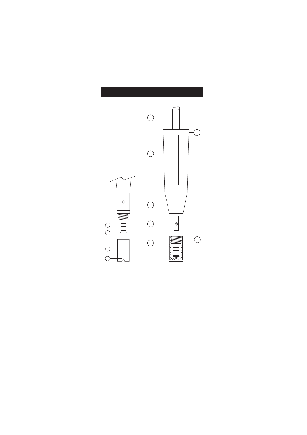
PROBE FUNCTIONAL DESCRIPTIONPROBE FUNCTIONAL DESCRIPTION
PROBE FUNCTIONAL DESCRIPTION
PROBE FUNCTIONAL DESCRIPTIONPROBE FUNCTIONAL DESCRIPTION
1. DO Probe
2. Protective Cap
3. Watertight Shielded Cable
4. Polypropylene Probe Body
5. Temperature Sensor
6. O-Ring Seal
7. Silver Chloride Anode
8. Platinum Cathode (sensor)
9. Oxygen Permeable PTFE Membrane
10. Membrane Cap
4
Page 5
FUNCTIONAL DESCRIPTIONFUNCTIONAL DESCRIPTION
FUNCTIONAL DESCRIPTION
FUNCTIONAL DESCRIPTIONFUNCTIONAL DESCRIPTION
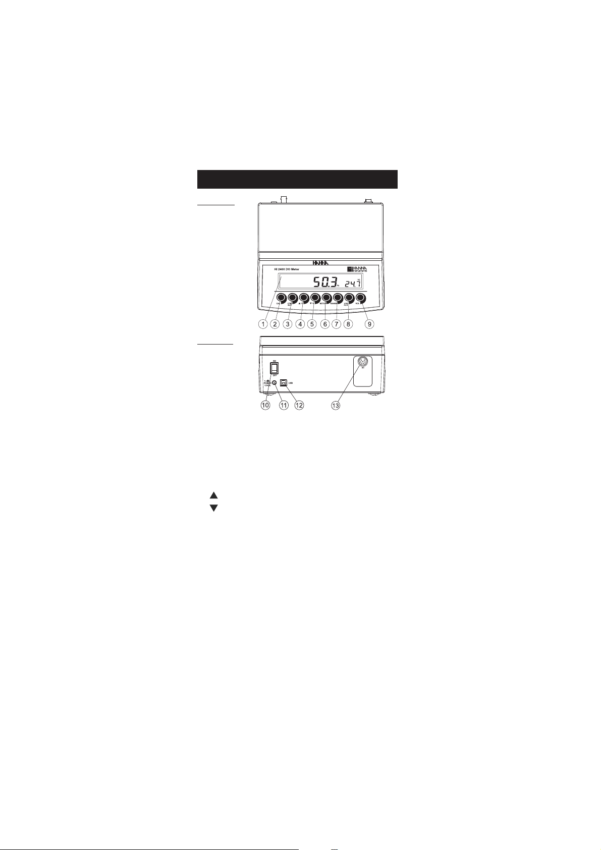
Front Panel
Rear Panel
1) Liquid Crystal Display (LCD).
2) CAL key, to enter and exit calibration mode.
3) CFM/GLP key, to confirm calibration selection, different setup values
or to display Good Laboratory Practice information.
4) ºC key, to manually increase temperature value or other parameters.
5) ºC key, to manually decrease temperature value or other parameters.
6) SETUP key, to enter/exit SETUP mode.
7) RANGE key, to select measurement range (% or ppm), switch to
focused data in SETUP or toggle between standard value and
temperature during calibration.
8) LOG/CLR key, to store a value into memory, or to select to delete log
records.
9) RCL key, to enter and exit view memory mode.
10) ON/OFF switch.
11) Power supply socket.
12) USB connector.
13) DO probe connector.
5
Page 6
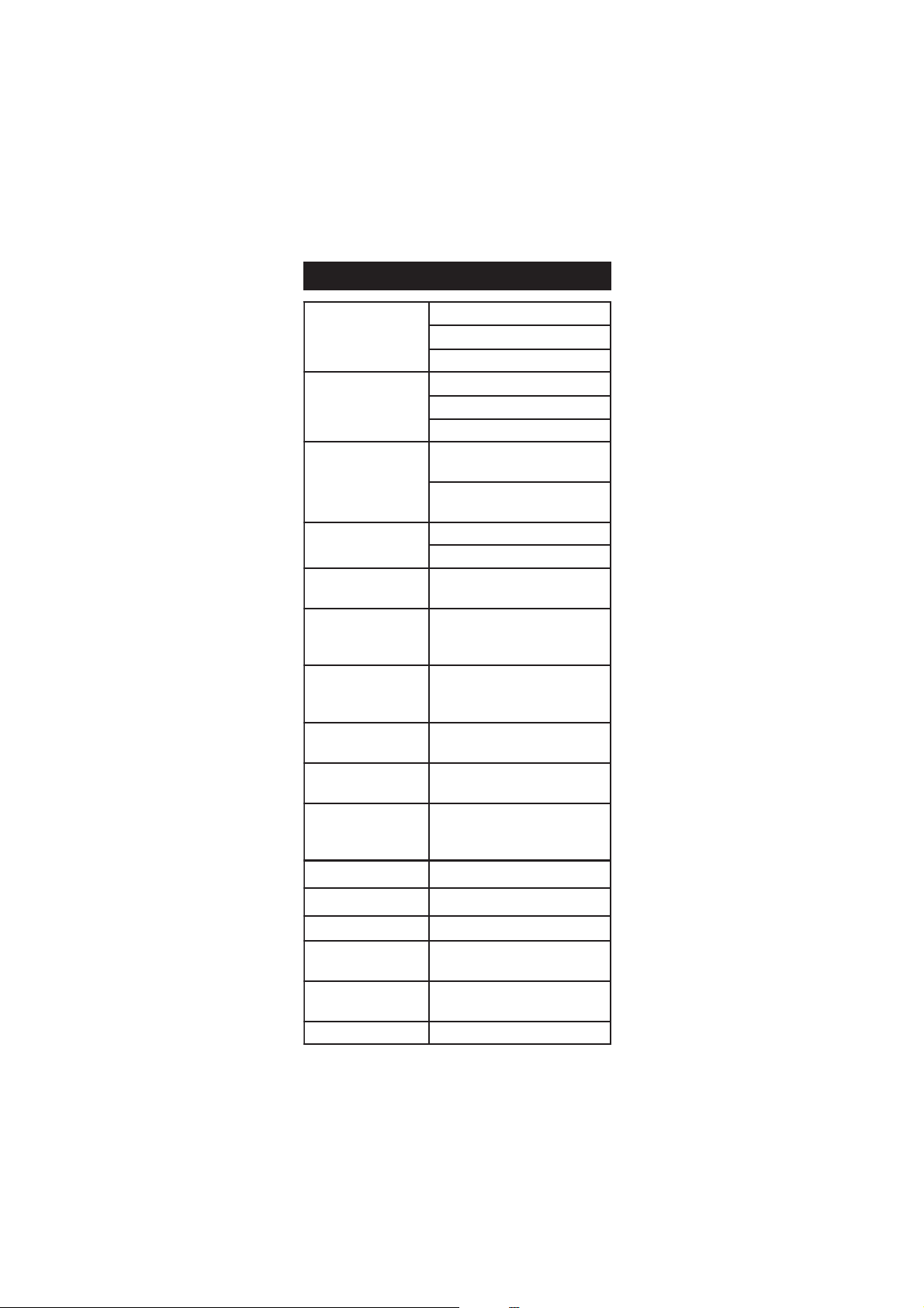
SPECIFICATIONSSPECIFICATIONS
EGNAR
mpp00.54ot00.0
%0.003ot0.0
)F°221ot0.23(Cº0.05ot0.0
NOITULOSER
mpp10.0
%1.0
C°1.0
YCARUCCA
F°86/C°02@
,tigid1±roelacslluffo%5.1±
retaergsirevehcihw
)rorreeborpgnidulcxe(Cº2.0±
noitaiveDCMElacipyT
elacslluffo%5.1±
Cº5.0±
noitarbilaCOD
%0tatniopelbuodroelgniS
( 0407IH )riani(%001dna)
edutitlA
noitasnepmoC
noituloseR
)'021,31(m000,4ot0
)'823(m001
ytinilaS
noitasnepmoC
noituloseR
l/g04ot0
l/g1
noitasnepmoCerutarepmeT
Cº0.05ot0.0
)Fº221ot0.23(
eborP
2/70467IH htiw
elbac)'6.6(m2
lavretnigniggoL
sdnoces03,01,5
,021,06,03,51,01,5,2,1ro
setunim081
noitacinummocCP BSUdetalosiotpO
ylppusrewoP retpadaCDV21
snoisnemiD )”3.4x7.8x2.9(mm901x222x532
thgieW
)bl9.2(gK3.1
)bl6.4(gK1.2redlohhtiwtik
tnemnorivnE
)Fº221-23(Cº05–0
gnisnednocnonHR%59.xam
ytnarraW sraey2
SPECIFICATIONS
SPECIFICATIONSSPECIFICATIONS
6
Page 7
Shipping
cap
black
red
FILLFIRST
THENTAP
THENSCREW
BACKON
OPERATIONAL GUIDEOPERATIONAL GUIDE
OPERATIONAL GUIDE
OPERATIONAL GUIDEOPERATIONAL GUIDE
POWER CONNECTION
Plug the 12 VDC adapter into the power supply socket.
Notes: • This instrument use non volatile memory to retain the
calibration parameters and all the other settings even when
unplugged.
• Make sure a fuse protects the main line.
PROBE CONNECTION AND PREPARATION
To take measurements, connect the DO probe to the meter securely by
aligning the pins with the socket located on the back of the meter,
pushing the plug in and tightening the threaded ring.
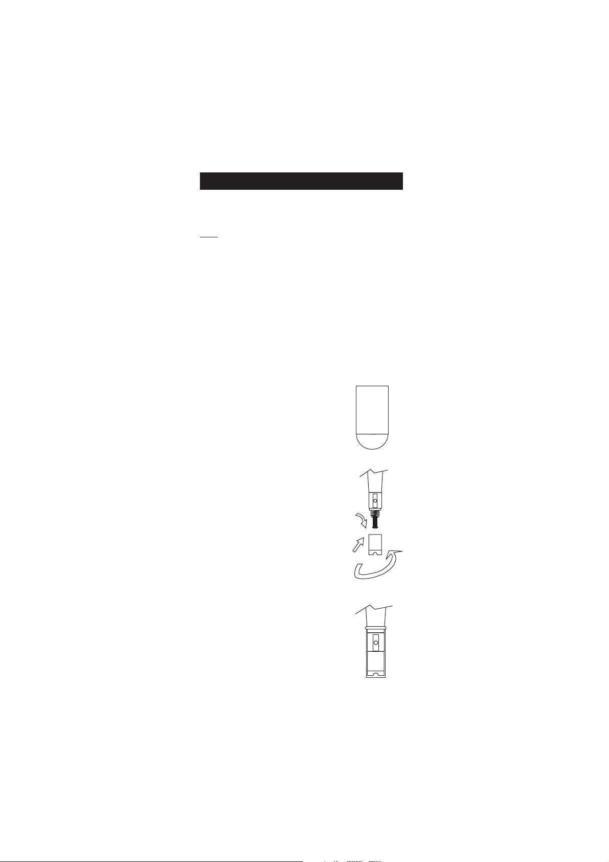
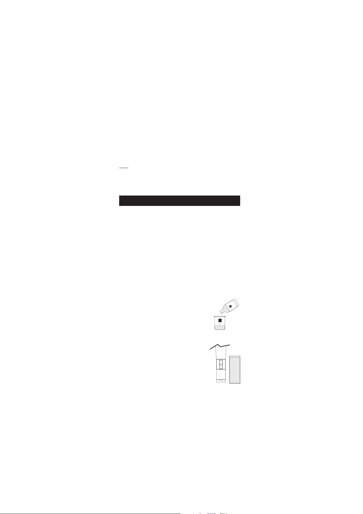
Probes shipped from Hanna Instruments are dry. To hydrate the probe
and prepare it for use, connect it to the
meter and proceed as follows:
1. Remove the red and black plastic
cap. This cap is for shipping purposes
and can be thrown away.
2. Wet the sensor by soaking the bottom
2½ cm (1") of the probe in electrolyte
(HI 7041S) for 5 minutes.
3. Rinse the membrane cap (HI 76407A
supplied in the kit with the meter)
with electrolyte solution while shaking
it gently. Refill with clean electrolyte
solution.
4. Tap gently the sides of the membrane
cap with your finger tip to ensure
that no air bubbles are trapped. To
avoid damaging the membrane, do
not tap it directly on the bottom.
5. Make sure that the rubber O-ring
sits properly inside the membrane
cap.
6. With the sensor facing down,
slowly screw the cap clockwise.
Some electrolyte will overflow.
When not in use and during polarization
(see page 8), use the protective transparent
cap supplied in the kit with the meter.
7
Page 8
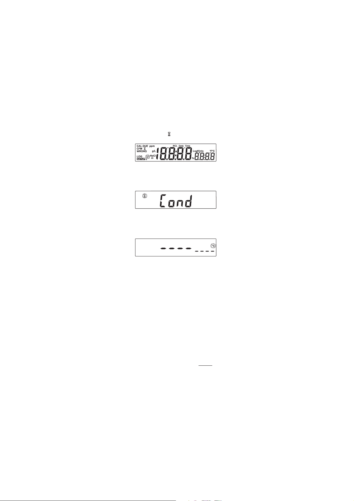
INSTRUMENT START-UP
• Turn the instrument on by pressing the ON/OFF switch.
• All LCD tags are displayed and a beep is generated while the
instrument performs a self test.
• The instrument will display “ ” blinking until initialization is complete.
• After a few seconds “Cond” message appears on the LCD to inform
the user that the probe is in auto-conditioning (automatic polarization)
mode.
• When this message disappears, the probe is polarized and the
instrument can be calibrated.
• If the probe is disconnected, the meter will display “----”.
PROBE POLARIZATION
The probe is under polarization with a fixed voltage of approximately
800 mV.
Probe polarization is essential for stable measurements with the same
recurring degree of accuracy.
With the probe properly polarized, oxygen is continually consumed when
it passes through the sensitive diaphragm and dissolves in the electrolyte
solution contained in the probe.
If polarization is interrupted, the electrolyte solution continues to be
enriched with oxygen until it reaches an equilibrium with the surrounding
solution.
Whenever measurements are taken with a non-polarized probe, the
oxygen level revealed is both that of the tested solution, as well as that
present in the electrolyte solution. This reading is incorrect.
The calibration of this instrument is very simple.
Before proceeding with the calibration, make sure the probe is ready for
measurements (see page 7), i.e. the membrane cap is filled with electrolyte
and the probe is connected to the meter and properly polarized.
8
Page 9
For an accurate calibration, it is recommended to wait at least 15 minutes
to ensure precise conditioning of the probe.
Keep the protective cap on during polarization time and remove it for
calibration and measurements. Follow the calibration procedure (see
page 10).
SALINITY AND ALTITUDE COMPENSATION
If the sample contains significant concentration of salinity or if you are
performing measurements at an altitude different from sea level, the
read out values must be corrected, taking into account the lower degree
of oxygen solubility in these situations (see pages 15-16).
Remember to set the altitude and/or the salinity before taking any DO
measurements. The meter will automatically compensate for these factors.
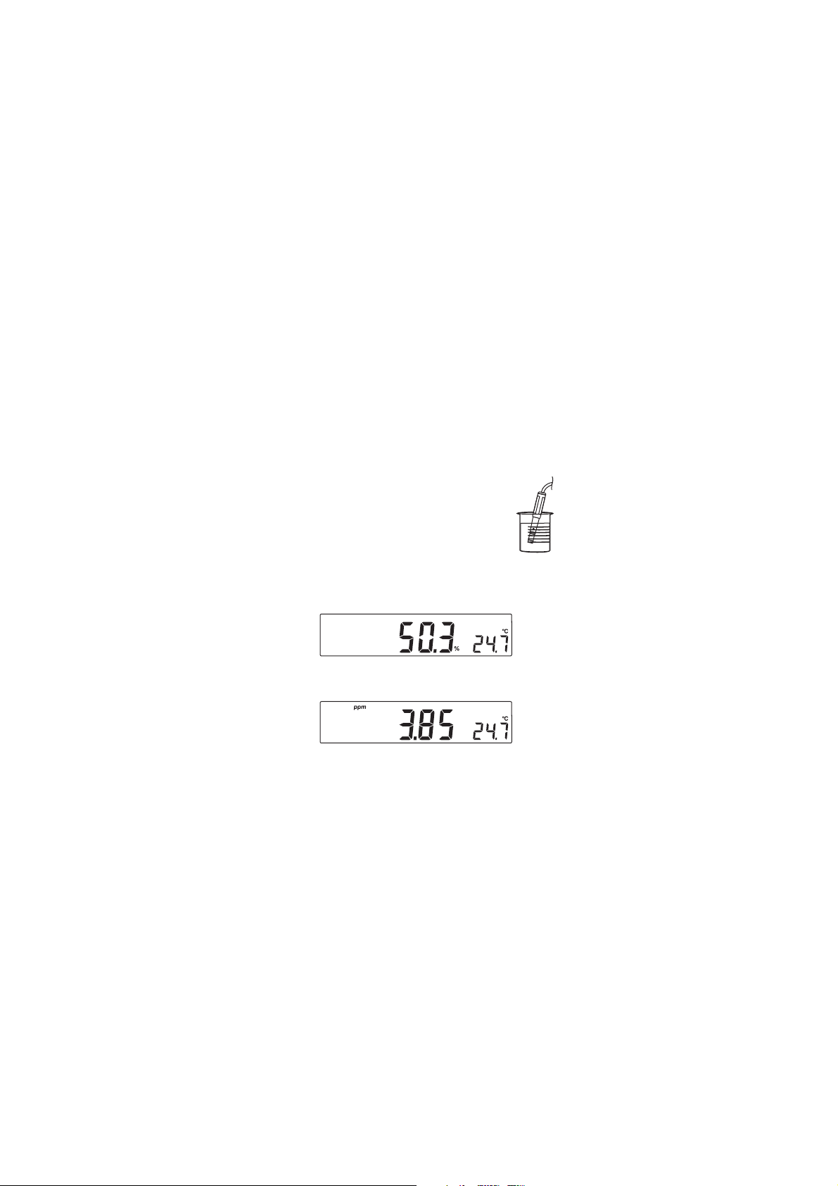
DO MEASUREMENTS
Make sure that the instrument has been calibrated and
the protective cap has been removed.
• Submerse the tip of the probe in the sample to be
tested. Allow approximately one minute for the reading
to stabilize.
• The Dissolved Oxygen value (in %) is displayed on the primary LCD
and the temperature on the secondary LCD.
• Press RANGE to change the reading from % to ppm and vice-versa.
For accurate Dissolved Oxygen measurements, a water movement of
0.3 m/s is required. This is to ensure that the oxygen-depleted
membrane surface is constantly replenished. A moving stream will
provide adequate circulation.
The use of a magnetic stirrer to ensure a certain fluid velocity is
recommended.
9
Page 10
TEMPERATURE MEASUREMENTS
HI 7040
HI 7040
The probe has a built-in temperature sensor.
The measured temperature is indicated on the secondary LCD as shown
above.
Allow the probe to reach thermal equilibrium before taking any measurement.
This can take several minutes. The greater the difference between the
temperature at which the probe was stored and the temperature of the
sample, the longer the time will be.
Note: If “----” is displayed, the DO probe is not properly connected. This
also indicates the posibility of a broken probe cable. If temperature
displayed blinking, the temperature is out of range.
DO CALIBRATIONDO CALIBRATION
DO CALIBRATION
DO CALIBRATIONDO CALIBRATION
Calibrate the instrument frequently, especially if high accuracy is
required.
The instrument can be calibrated in maximum 2 points: 0.0% (zero
calibration) and 100.0% (slope calibration).
The zero calibration of the HI 2400 is very stable, therefore this procedure
needs to be performed only whenever the probe or the membrane is
replaced.
However, because the slope calibration is more critical, it is recommended
to perform this procedure every week.
INITIAL PREPARATION
• Pour small quantities of HI 7040 Zero Oxygen
solution into a beaker. If possible, use a plastic
beaker to minimize any EMC interferences.
• Make sure the probe is ready for measurements
(see probe preparation on page 7), i.e. the
membrane is filled with electrolyte and the probe
is connected to the meter.
• Switch the meter on by pressing the ON/OFF
switch.
• For an accurate calibration, it is recommended
to wait for at least 15 minutes to ensure precise
conditioning of the probe.
• Remove the protective cap from the DO probe.
• Set the appropriate altitude factor (see page 15). Make sure the
salinity factor is set to zero (see page 16).
10
Page 11

ZERO CALIBRATION
OR
zero oxygen
• Submerse the probe into HI 7040
solution and stir gently for 2-3 minutes.
• Press CAL. The “~” and “ ” tags will blink on the
LCD until the reading is stable.
• When the reading is stable, “CFM” starts blinking.
Press CFM to confirm the “0.0%” DO calibration.
• If the reading is within the limits (±15% f.s.), the
meter stores the value (and adjusts the slope point).
• Press CAL. The instrument will return to measurement
mode and will memorize the zero calibration data.
For a two-point calibration do not press CAL and
follow the procedure below.
SLOPE CALIBRATION
It is suggested to perform the slope calibration in air.
• Rinse the probe in clean water to remove any residual
zero oxygen solution.
Note: If you did not perform the zero calibration procedure, press CAL
and then the ARROW keys to select the 100% DO calibration
point.
• Dry the probe tip and allow a few seconds for the LCD reading to
stabilize. The “
stable.
• When the reading is stable, “CFM” tag starts blinking. Press CFM to
confirm the “100.0%” DO calibration.
• If the reading is within the limits (±15% f.s.), the
meter stores the value (and adjusts the slope point).
~~
~” and “ ” tags will blink until the reading is
~~
11
Page 12

• The instrument stores the slope calibration data and returns to
measurement mode.
Notes: • If the reading is not close to the selected value, “WRONG“
tag will blink.
• If the temperature goes out of range during calibration the
“WRONG”, temperature unit tag and both measurements
will blink.
• HI 2400 has automatic buffer recognition function. If the
ARROW keys are pressed to select the desired calibration
value, the automatic buffer recognition function is disabled.
12
Page 13

GOOD LABORATORY PRACTICE (GLP)GOOD LABORATORY PRACTICE (GLP)
GOOD LABORATORY PRACTICE (GLP)
GOOD LABORATORY PRACTICE (GLP)GOOD LABORATORY PRACTICE (GLP)
GLP is a set of functions that allows storage and retrieval of data
regarding the maintenance and status of the system.
All data regarding DO calibration is stored for the user to review when
necessary.
LAST DO CALIBRATION DATA
The last DO calibration data is stored automatically after a successful
calibration. To view the DO calibration data, press GLP when the
instrument is in measurement mode.
The instrument will display the time (hh:mm) of the last calibration.
Press the ARROW keys to view the next calibration parameter.
Pressing the key:
• The date of the calibration.
• The calibration standards.
• Press SETUP to view the temperature of the calibration.
• The altitude value.
• The salinity value.
13
Page 14

• The instrument ID.
SETUPSETUP
SETUP
SETUPSETUP
Setup mode allows viewing and modifying the following parameters:
• Salinity Factor
• Altitude Factor
• Log Interval
• Current Time (hour & minute)
• Current Date (month, day & year)
• Beep Status
• Instrument ID
• Temperature Unit
To enter the Setup mode press SETUP while the instrument is in
measurement mode. Press SETUP again to exit SETUP mode.
Select a parameter with the ARROW keys.
Press CAL if you want to change a parameter value. The selected
parameter will blink.
Press RANGE to toggle between displayed parameters.
Press the ARROW keys to increase or decrease the displayed value.
Press CFM to save the modified value or CAL to escape.
Press the ARROW keys to select the next/previous parameter.
SALINITY FACTOR
Press CAL when the salinity factor is displayed. The salinity factor (“0” to
“40” g/l) and the “CFM” tag will start blinking.
Press ARROW
Press CFM to save the modified value or press CAL to escape without
saving.
The salinity affects the DO concentration, decreasing its value. The next
table shows the maximum oxygen solubility at various temperatures and
salinity levels.
keys to change the salinity factor value.
14
Page 15

Cº
leveLaeSta)l/g(ytinilaS
Fº
l/g0 l/g01 l/g02 l/g03 l/g53
0 06.41 46.31 47.21 09.11 05.11 0.23
2 18.31 19.21 70.21 92.11 19.01 6.53
4 90.31 52.21 74.11 37.01 83.01 2.93
6 44.21 56.11 19.01 22.01 98.9 8.24
8 38.11 90.11 04.01 57.9 44.9 4.64
01 82.11 85.01 39.9 23.9 30.9 0.05
21 77.01 11.01 05.9 29.8 56.8 6.35
41 92.01 86.9 01.9 55.8 03.8 2.75
61 68.9 82.9 37.8 12.8 79.7 8.06
81 54.9 09.8 93.8 09.7 66.7 4.46
02 80.9 65.8 70.8 06.7 83.7 0.86
22 37.8 32.8 77.7 33.7 21.7 6.17
42 04.8 39.7 94.7 70.7 78.6 2.57
52 42.8 97.7 63.7 59.6 57.6 0.77
62 90.8 56.7 32.7 38.6 46.6 8.87
82 18.7 83.7 89.6 16.6 24.6 4.28
03 45.7 41.7 57.6 93.6 22.6 0.68
23 92.7 09.6 45.6 91.6 30.6 6.98
43 50.7 86.6 33.6 10.6 58.5 2.39
63 28.6 74.6 41.6 38.5 86.5 8.69
83 16.6 82.6 69.5 66.5 15.5 4.001
04 14.6 90.6 97.5 05.5 63.5 0.401
24 22.6 39.5 36.5 53.5 22.5 6.701
44 40.6 77.5 84.5 12.5 90.5 2.111
64 78.5 16.5 33.5 70.5 79.4 8.411
84 07.5 74.5 02.5 59.4 58.4 4.811
05 45.5 33.5 70.5 38.4 57.4 0.221
Note: The relationship between salinity and chlorinity for sea water is
given by the equation below:
Salinity (g/l) = 1.80655 Chlorinity (g/l)
ALTITUDE FACTOR
Press CAL when the altitude factor is displayed. The altitude factor
(“0” to “4000” m, in steps of 100 m; 1 meter = 3.28 feet) and the
“CFM” tag will start blinking.
Press the ARROW
keys to change the altitude factor value.
Press CFM to save the modified value or press CAL to escape without saving.
15
Page 16

Cº
leveLaeSevobasreteM,edutitlA
Fº
m0
003m006m009m0021m0051m0081m0012m0042m0072m0003m0033m0063m0093m0004
m
0 6.41 1.41 6.31 1.31 6.21 1.21 7.11 2.11 8.01 4.01 0.01 7.9 3.9 0.9 9.8 0.23
2 8.31 3.31 8.21 4.21 9.11 5.11 0.11 6.01 2.01 9.9 5.9 2.9 8.8 5.8 4.8 6.53
4 1.31 6.21 2.21 7.11 3.11 9.01 5.01 1.01 7.9 3.9 0.9 7.8 4.8 0.8 9.7 2.93
6 4.21 0.21 5.11 1.11 7.01 3.01 9.9 6.9 2.9 9.8 6.8 2.8 9.7 6.7 5.7 8.24
8 8.11 4.11 0.11 6.01 2.01 8.9 5.9 1.9 8.8 4.8 1.8 8.7 5.7 3.7 2.7 4.64
01 3.11 9.01 5.01 1.01 7.9 4.9 0.9 7.8 4.8 1.8 8.7 5.7 2.7 9.6 8.6 0.05
21 8.01 4.01 0.01 6.9 3.9 9.8 6.8 3.8 0.8 7.7 4.7 1.7 9.6 6.6 5.6 6.35
41 3.01 9.9 6.9 2.9 9.8 5.8 2.8 9.7 6.7 4.7 1.7 8.6 6.6 3.6 2.6 2.75
61 9.9 5.9 2.9 8.8 5.8 2.8 9.7 6.7 3.7 0.7 8.6 5.6 3.6 1.6 0.6 8.06
81 5.9 1.9 8.8 5.8 1.8 8.7 6.7 3.7 0.7 8.6 5.6 3.6 0.6 8.5 7.5 4.46
02 1.9 8.8 4.8 1.8 8.7 5.7 3.7 0.7 7.6 5.6 2.6 0.6 8.5 6.5 5.5 0.86
22 7.8 4.8 1.8 8.7 5.7 2.7 0.7 7.6 5.6 2.6 0.6 8.5 6.5 4.5 3.5 6.17
42 4.8 1.8 8.7 5.7 2.7 0.7 7.6 5.6 2.6 0.6 8.5 6.5 4.5 2.5 1.5 2.57
52 3.8 0.8 7.7 4.7 1.7 8.6 6.6 4.6 1.6 9.5 7.5 5.5 3.5 1.5 0.5 0.77
62 1.8 8.7 5.7 2.7 0.7 7.6 5.6 2.6 0.6 8.5 6.5 4.5 2.5 0.5 9.4 8.87
82 8.7 5.7 3.7 0.7 7.6 5.6 2.6 0.6 8.5 6.5 4.5 2.5 0.5 8.4 7.4 4.28
03 6.7 3.7 0.7 8.6 5.6 3.6 0.6 8.5 6.5 4.5 2.5 0.5 8.4 6.4 6.4 0.68
23 3.7 0.7 8.6 5.6 3.6 1.6 8.5 6.5 4.5 2.5 0.5 8.4 7.4 5.4 4.4 6.98
43 1.7 8.6 6.6 3.6 1.6 9.5 6.5 4.5 2.5 0.5 9.4 7.4 5.4 3.4 3.4 2.39
63 8.6 6.6 3.6 1.6 9.5 7.5 5.5 3.5 1.5 9.4 7.4 5.4 4.4 2.4 1.4 8.69
83 6.6 4.6 1.6 9.5 7.5 5.5 3.5 1.5 9.4 7.4 5.4 4.4 2.4 1.4 0.4 4.001
04 4.6 2.6 9.5 7.5 5.5 3.5 1.5 9.4 7.4 6.4 4.4 2.4 1.4 9.3 9.3 4.401
24 2.6 0.6 8.5 6.5 3.5 2.5 0.5 8.4 6.4 4.4 3.4 1.4 0.4 8.3 8.3 6.701
44 0.6 8.5 6.5 4.5 2.5 0.5 8.4 6.4 5.4 3.4 1.4 0.4 8.3 7.3 7.3 2.111
64 8.5 6.5 4.5 2.5 0.5 8.4 7.4 5.4 3.4 2.4 0.4 9.3 7.3 6.3 5.3 8.411
84 7.5 5.5 3.5 1.5 9.4 7.4 5.4 4.4 2.4 0.4 9.3 7.3 6.3 5.3 4.3 4.811
05 5.5 3.5 1.5 9.4 7.4 6.4 4.4 2.4 1.4 9.3 8.3 6.3 5.3 4.3 3.3 0.221
16
Page 17

LOG INTERVAL
Press CAL when log interval is displayed. The log interval and “CFM”
tag is displayed blinking.
Press the ARROW keys to change the custom buffer value.
Press CFM to confirm the selection.
Press CAL to escape without saving.
CURRENT TIME
Press CAL when the current time is displayed. The hour and “CFM” tag will
start blinking.
Press the ARROW
Press RANGE. The minutes will start blinking.
Press the ARROW keys to change the minutes.
Press CFM to save the modified value.
Press CAL to escape without saving.
CURRENT DATE
Press CAL when the current date is displayed. The month and “CFM” tag
will start blinking.
Press the ARROW
Press RANGE. The day and “CFM” tag will start blinking.
Press the ARROW
Press RANGE. The year and “CFM” tag will start blinking.
keys to change the hour.
keys to change the month.
keys to change the day.
Press the ARROW keys to change the year.
17
Page 18

Press CFM to save the modified value.
Press CAL to escape without saving.
BEEP STATUS
Press CAL when the beep status is displayed. The beep status (“ON” or
“OFF”) and “CFM” tag will start blinking.
Press the ARROW
Press CFM to save the modified value or press CAL to escape without
saving.
INSTRUMENT ID
Press CAL when “InId” is displayed. The instrument ID (“0000“ to
“9999“) and “CFM” tag will start blinking.
Press the ARROW
Press CFM to save the modified instrument ID value.
Press CAL to escape without saving.
Note: The instrument ID is downloaded to a PC as part of a logged
data, set to identify its origin.
TEMPERATURE UNIT
Press CAL when “Unit“ is displayed. The temperature unit and “CFM”
tag will start blinking.
keys to change the beep status.
keys to change the instrument ID value.
Press the ARROW keys to change the option.
Press CFM to save the modified temperature unit.
Press CAL to escape without saving.
18
Page 19

LOGGINGLOGGING
LOGGING
LOGGINGLOGGING
This function allows the user to log DO (in ppm or %) together with
temperature automatically, for long periods of time. All logged data can
be stored into a PC through the USB port.
The memory used for storing the logged data is divided in 32 pages. The
capacity of each page is 250 samples. The lot number goes from 1 to
100. The maximum capacity of the log memory is 8000 samples. Each
time a new lot starts, it automatically starts from a new page. When the
samples collected for a single lot reach the limit (8000 samples) or all
memory pages are occupied, the meter stops logging automatically.
The appropriate logging interval can be set between 5, 10, 30 seconds
or 1, 2, 5, 10, 15, 30, 60, 120, 180 minutes (see SETUP section for
details).
LOGGING THE CURRENT DATA
To start the Auto LOG mode press LOG while in measurement
mode.
When the selected interval is reached the instrument will display the
current lot number on the primary LCD line, the record number on the
secondary LCD line and the LOG tag ( see example below: Lot 15 record 22)
followed by the number of free records on the corresponding memory
space.
If there are less than 6 memory locations remaining, the record number
and “Lo” message will be displayed to alert the user.
To stop the Auto LOG mode press LOG again. The “LOG” tag will be
cleared.
19
Page 20

If the log space is full, the “FULL LOG” message will be displayed and
no more data will be saved.
Note: When pressing any key that is not active, while lot logging is
running, the following message is displayed for a few seconds.
VIEW LOGGED DATA
Press the RCL
key while in measurement mode to retrieve the stored
information.
If no lots are memorized, the next messages will be displayed:
Otherwise, the instrument will display “L” and the lot number on the
primary LCD and the number of records on the secondary LCD, “RCL” tag
and “CFM” blinking.
Press ARROW keys to select different lot.
Press CFM to view record information. Then the record information will
appear. To view the record number at any time just press the SETUP
key.
Use the ARROW keys to scroll through the records.
To view additional information press RANGE:
• The time on the primary LCD, along with “TIME” tag and the
seconds on the secondary LCD.
20
Page 21

• The date on the primary LCD, along with “DATE”, month and day
tags.
• The salinity on the primary LCD and “SAL” message on the secondary
LCD.
• The altitude on the primary LCD and “ALt” message on the
secondary LCD.
• The interval for lot logging.
TO DELETE LOTS
To delete a lot, use the ARROW keys to select the desired lot. Press CLR key.
The “dEL” message is displayed on the primary LCD and the selected lot on
the secondary LCD, along with ”RCL” tag.
• The ARROW keys can be used to change the lot number.
• Press SETUP to select delete all lots feature. The display will show
“dEL” in the primary LCD and “ALL” in the secondary LCD.
• Press CFM to confirm delete.
• Press CAL, CLR or RCL to escape and return to the RCL screen.
• If “dEL ALL” option was selected, all the lots are deleted. The “no rEc”
message will appear.
• Press RCL exit record information and enter lot information.
• Press RCL again to return to measurement mode.
21
Page 22

TEMPERATURE CALIBRATIONTEMPERATURE CALIBRATION
TEMPERATURE CALIBRATION
TEMPERATURE CALIBRATIONTEMPERATURE CALIBRATION
((
for technical personnel onlyfor technical personnel only
(
for technical personnel only
((
for technical personnel onlyfor technical personnel only
Each meter has been factory calibrated for temperature with the supplied
DO probe and is ready for measurements.
The DO probes are interchangeable and no temperature calibration is
needed.
If the temperature measurements are not accurate, temperature
recalibration should be performed.
For an accurate recalibration, contact your dealer or the nearest Hanna
Customer Service Center, or follow the procedure below.
• Prepare a vessel containing ice and water and another one containing
hot water (at a temperature of around 50 °C). Place insulation
material around the vessels to minimize temperature changes.
• Use a calibrated thermometer with a resolution of 0.1 °C as a
reference thermometer. Connect the HI 76407/2 DO probe to the
appropriate socket.
• With the instrument off, press and hold down CFM&SETUP, then
power on the instrument. The “CAL” tag will appear and the
secondary LCD will show “0.0 °C”.
))
)
))
• Submerse the DO probe in the vessel with ice
and water as near as possible to the reference
thermometer. Allow a few seconds for the probe
to stabilize.
• Use the ARROW keys to set the reading on
the secondary LCD to that of ice and water,
measured by reference thermometer. When
the reading is stable, the “CFM” tag starts blinking.
• Press CFM to confirm. The secondary LCD will show “50.0 °C”.
22
Page 23

• Submerse the DO probe in the second vessel
as near as possible to the reference thermometer. Allow a few seconds for the probe to
stabilize.
• Use the ARROW keys to set the reading on
the secondary LCD to that of the hot water.
• When the reading is stable, the “CFM” tag starts
blinking.
• Press CFM to confirm. The instrument returns to
measurement mode.
Note: If the reading is not close to the selected calibration point,
“WRONG” tag will blink. In this case, check if the value set on the
secondary LCD and the temperature measured with reference
thermometer are close. Change the DO probe or restart calibration
if necessary.
23
Page 24

PC INTERFACEPC INTERFACE
PC INTERFACE
PC INTERFACEPC INTERFACE
Data transmission from the instrument to the PC can be done with the
HI 92000 Windows® compatible software (optional). HI 92000 also
offers graphing and an on-line help feature.
Data can be exported to the most popular spreadsheet programs for
further analysis.
To connect your instrument to a PC, use a standard USB cable. Make
sure that your instrument is switched off and plug one connector to the
instrument’s USB socket and the other to the USB port of your PC.
Note: If you are not using Hanna Instruments HI 92000 software,
please see the following instructions.
SENDING COMMANDS FROM PC
It is also possible to remotely control the instrument with any terminal
program. Use a standard USB cable to connect the instrument to a PC,
start the terminal program and set the communication options as follows:
8, N, 1, no flow control, baud rate 9600.
COMMAND TYPES
To send a command to the instrument follow the next scheme:
<command prefix> <command> <CR>
where: <command prefix> is a selectable ASCII character
between 0 and 47 (default 16).
<command> is the command code.
Note: Either small or capital letters can be used.
SIMPLE COMMANDS
RNG Is equivalent to pressing RANGE
CAL Is equivalent to pressing CAL
CFM Is equivalent to pressing CFM
UPC Is equivalent to pressing the UP arrow key
DWC Is equivalent to pressing the DOWN arrow key
LOG Is equivalent to pressing LOG
RCL Is equivalent to pressing RCL
SET Is equivalent to pressing SETUP
24
Page 25

CHR xx Change the instrument range according with the parameter
value (xx):
• xx=06 % range
• xx=07 ppm range
The instrument will answer for these commands with:
<STX> <answer> <ETX>
where: <STX> is 02 ASCII code character (start of text)
<ETX> is 03 ASCII code character (end of text)
<answer>:
<ACK> is 06 ASCII code character (recognized command)
<NAK> is 21 ASCII code character (unrecognized command)
<CAN> is 24 ASCII code character (corrupted command)
COMMANDS REQUIRING AN ANSWER
The instrument will answer for these commands with:
<STX> <answer> <checksum> <ETX>
where the checksum is the bytes sum of the answer string sent as 2 ASCII
characters.
All the answer messages are with ASCII characters.
RAS Causes the instrument to send a complete set of readings.
The answer string contains:
• Meter mode (2 chars):
• 06 - % range
• 07 - ppm range
• Meter status (2 chars of status byte): represents a 8
bit hexadecimal encoding.
• 0x10 - temperature probe is connected
• 0x01 - new GLP data available
• 0x02 - new SETUP parameter
• Reading status (1 char): R - in range, O - over
range, U - under range.
• The reading (corresponding to the selected range) 7 ASCII chars, including sign and decimal point.
• Temperature reading - 7 ASCII chars, with sign and
two decimal points, always in ºC.
25
Page 26

MDR Requests the instrument model name and firmware code
(16 ASCII chars).
GLP Requests the calibration data record.
The answer string contains:
• GLP status (1 char): represents a 4 bit hexadecimal
encoding.
• 0x04 - DO calibration available
• DO calibration data (if available), which contains:
• the number of calibrated satandards (1 char)
• the calibration time, yymmddhhmmss (12 chars)
• standards information
• standard value, with sign and decimal point
(7 chars).
• the standard temperature, with sign and decimal
point (7 chars)
• the salinity value (4 chars)
• the altitude value (4 chars)
PAR Requests the setup parameters setting.
The answer string contains:
• Instrument ID (4 chars)
• SETUP information (2 chars): 8 bit hexadecimal
encoding.
• 0x01 - beep ON (else OFF)
• 0x04 - degrees Celsius (else degrees Fahrenheit)
• Log type - 01 to 12 - the coresponding interval for
lot log (5 s to 180 min)
• Salinity value (4 chars)
• Altitude value (4 chars)
LLsxff: requests information about all lots and it sends the information in
frames of 10 lots each (a frame contains information about 10 lots)
Command Parameters:
x = D - request DO data
ff - requested frame number - first frame is labeled 01
26
Page 27

GLDxxxfff:Requests the records of the “xxx” lot number. The records are
sent in frames of 10 records; “fff” is the frame number (01 first
frame). (Example: Lot 13 has 53 records. The records will be
sent in 6 frame, 5 with10 records and 1 with 3 records.)
Command Parameters:
xxx - Lot number (eq: for lot number 1 xxx = 001)
fff - requested frame number - first frame is labeled 01
Notes: • “Err3” is sent if the Log on demand is empty.
• “Err4” is sent if the requested set parameter is not available.
• “Err5” is sent if the command argument is wrong.
• “Err6” is sent if the requested range is not available.
• “Err7” is sent if the instrument is logging.
• “Err8” is sent if the instrument is not in measurement mode.
• Invalid commands will be ignored.
27
Page 28

PROBE & MEMBRANE MAINTENANCEPROBE & MEMBRANE MAINTENANCE
TWIST
AND
PULL
UNSCREW
fig.1
fig.2
PROBE & MEMBRANE MAINTENANCE
PROBE & MEMBRANE MAINTENANCEPROBE & MEMBRANE MAINTENANCE
The oxygen probe body is made of reinforced plastic for maximum
durability.
A thermistor temperature sensor provides temperature measurements of
the sample. Use the protective probe cap when not in use.
To replace the membrane or refill with electrolyte, proceed as follows:
• Remove the protective cap by gently
twisting and pulling it off the body of
the probe (see fig. 1).
• Unscrew the membrane cap by turning
it counterclockwise (see fig. 2).
• Wet the sensor by soaking the bottom
2½ cm (1") of the probe in electrolyte
(HI 7041S) for 5 minutes.
• Rinse the new membrane cap
(HI 76407A), supplied with the meter
with electrolyte solution while shaking
it gently. Refill with clean electrolyte
solution.
• Gently tap the sides of the membrane
cap with your finger tip to ensure that
no air bubbles remain trapped. Do not
tap directly the bottom with your finger,
as this will damage the membrane.
• Make sure that the rubber O-ring sits
properly inside the membrane cap.
• With the sensor facing down, slowly
screw the membrane cap clockwise.
Some electrolyte will overflow.
The Platinum cathode (#8 in the Functional
Description page 4) should always be bright
and untarnished. If it is tarnished or
stained, the cathode should be cleaned.
You can use a clean lint-free cardboard or
cloth. Rub the cathode very gently side to side 4-5 times. This will be
enough to polish and remove any stains without damaging the platinum
tip. Afterwards, rinse the probe with deionized or distilled water and
install a new membrane cap using fresh electrolyte and follow the steps
above. Recalibrate the instrument.
28
Page 29

SMOTPMYS MELBORP NOITULOS
puetautculfsgnidaeR
.)esion(nwoddna
toneveelseborpOD
.detresniylreporp
.eveelsehtresnI
ODswohsyalpsidehT
.gniknilbgnidaer
ODniegnarfotuO
.elacs
.retemehtetarbilaceR
noitulosehterusekaM
.egnardeificepsnisi
tonseodretemehT
ehterusaem
.erutarepmet
.eborpnekorB .eborpehtecalpeR
otsliafretemehT
sevigroetarbilac
.sgnidaerytluaf
.eborpnekorB .eborpehtecalpeR
retemehtputratstA
sgatDCLllasyalpsid
.yltnenamrep
sisyekehtfoenO
.dekcolb
rodraobyekehtkcehC
.rodnevehttcatnoc
" xxrrE egassemrorre"
.deyalpsid
.rorrelanretnI dnaretemehtfforewoP
ehtfI.notirewopneht
ehttcatnoc,stsisreprorre
.rodnev
LAC " dorP egassem"
.putratsta
yrotcaftontnemurtsnI
.detarbilac
lacinhceTannaHtcatnoC
yrotcafroftroppuS
.noitarbilac
Important
In order to have accurate and stable measurements, it is important that
the membrane surface is in perfect condition. This semipermeable
membrane isolates the sensor elements from the environment but allows
oxygen to enter. If any dirt is observed on the membrane, rinse carefully
with distilled or deionized water. If any imperfections still exist, or any
damage is evident (such as wrinkles or tears-holes), the membrane
should be replaced.
Make sure that the O-Ring sits properly in the membrane cap.
TROUBLESHOOTING GUIDETROUBLESHOOTING GUIDE
TROUBLESHOOTING GUIDE
TROUBLESHOOTING GUIDETROUBLESHOOTING GUIDE
29
Page 30

ACCESSORIESACCESSORIES
ACCESSORIES
ACCESSORIESACCESSORIES
HI 7040M Zero Oxygen Solution, 230 ml
HI 7040L Zero Oxygen Solution, 500 ml
HI 7041S Refilling Electrolyte Solution, 30 ml
HI 710005 115VAC to 12VDC converter
HI 710006 230VAC to 12VDC converter
HI 76407/2 Spare probe with 2 meters (6.7') cable
HI 76407/10 Spare probe with 10 meters (33') cable
HI 76407/20 Spare probe with 20 meters (67') cable
HI 76407A/P 5 spare membranes
HI 76404N Electrode holder
OTHER ACCESSORIES
HI 710005 Voltage adapter from 115 VAC to 12 VDC (USA plug)
HI 710006 Voltage adapter from 230 VAC to 12 VDC (European
plug)
HI 710012 Voltage adapter from 240 VAC to 12 VDC (UK plug)
HI 710013 Voltage adapter from 230 VAC to 12 VDC (South Africa
plug)
HI 710014 Voltage adapter from 230 VAC to 12 VDC (Australia
plug)
ChecktempC Pocket-size thermometer (range –50.0 to 150.0 ºC)
HI 76310 Platinum 4-ring conductivity/TDS probe with temperature
sensor and 1 m (3.3') cable
HI 92000 Windows® compatible software.
Windows® is registered Trademark of "Microsoft Co."
30
Page 31

RECOMMENDATIONS FOR USERS
Before using this product, make sure that it is entirely suitable for the
environment in which it is used.
Operation of this instrument in residential areas could cause unacceptable
interferences to radio and TV equipment, requiring the operator to follow
all necessary steps to correct interferences.
During operation, ESD wrist straps should be worn to avoid possible
damage to the electrode by electrostatic discharges.
Any variation introduced by the user to the supplied equipment may
degrade the instrument’s EMC performance.
To avoid electrical shock, do not use this instrument when voltages at the
measurement surface exceed 24 VAC or 60 VDC.
To avoid damage or burns, do not perform any measurement in
microwave ovens.
Hanna Instruments reserves the right to modify the design,
construction and appearance of its products without advance notice.
31
Page 32

Hanna Instruments Inc.
Highland Industrial Park
584 Park East Drive
Woonsocket, RI 02895 USA
Technical Support for Customers
Tel. (800) 426 6287
Fax (401) 765 7575
E-mail tech@hannainst.com
www.hannainst.com
Local Sales and Customer Service Office
Printed in EUROPE
(ROMANIA) MAN2400Y 07/10
32
 Loading...