

Page 1
HANNA LITERATURE
Instruction Manual
Hanna publishes a wide range of catalogs and handbooks for an
equally wide range of applications. The reference literature currently covers areas such as:
• Water Treatment
• Process
• Agriculture
• Food
• Laboratory
• Thermometry
and many others. New reference material is constantly being
added to the library.
For these and others catalogs, handbooks and leaflets, contact
your dealer or the Hanna Customer Service Center nearest to you.
To find the Hanna Office in your vicinity, check our home page at
www.hannainst.com
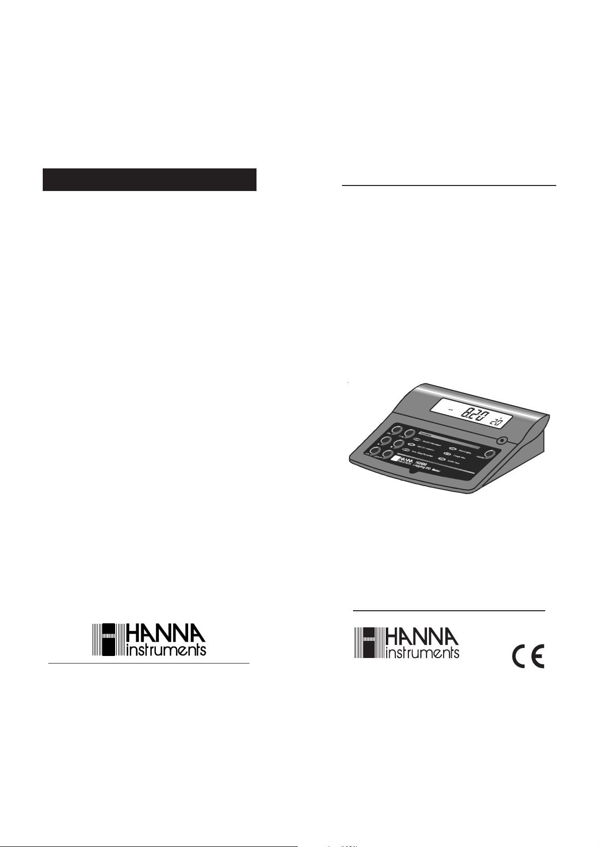
HI 2400
Microprocessor
Dissolved Oxygen
Bench Meter
MANHI2400
06/03
www.hannainst.com
This instrument is in compliance with the CE directives
WWW.HANNAINST.COM
Page 2
Dear Customer,
Thank you for choosing a Hanna Instruments product.
Please read this instruction manual carefully before using the instrument.
This manual will provide you with all the necessary information for the correct
use of the instrument, as well as a precise idea of its versatility in a wide range
of applications.
This instrument is in compliance with directives.
TABLE OF CONTENTS
PRELIMINARY EXAMINATION ............................................................................................3
GENERAL DESCRIPTION ....................................................................................................3
FUNCTIONAL DESCRIPTION PROBE ..................................................................................4
FUNCTIONAL DESCRIPTION OF HI 2400 ..........................................................................5
SPECIFICATIONS OF HI 2400 ............................................................................................7
LCD FUNCTIONAL DESCRIPTION .......................................................................................8
OPERATIONAL GUIDE ........................................................................................................8
D.O. CALI BRATION ..........................................................................................................12
TEMPERATURE CALIBRATION.........................................................................................16
SETUP .............................................................................................................................17
TEMPERATURE COMPENSATION ....................................................................................26
LOGGING FUNCTION ......................................................................................................26
INTERFACE WITH PC ......................................................................................................29
PROBE & MEMBRANE MAINTENANCE ...........................................................................30
ADDITIONAL INFORMATION ...........................................................................................32
ACCESSORIES .................................................................................................................37
WARRANTY ....................................................................................................................38
CE DECLARATION OF CONFORMITY ..............................................................................39
CE DECLARATION OF CONFORMITY
All rights are reserved. Reproduction in whole or in part is prohibited
without the written consent of the copyright owner, Hanna Instruments
Inc., 584 Park East Drive, Woonsocket, Rhode Island, 02895 , USA.
Visit our Internet Home Page:
www.hannainst.com
2
Recommendations for Users
Before using this product, make sure that it is entirely suitable for the environment in which it is used.
Operation of this instrument in residential area could cause unacceptable interference to radio and TV equipment,
requiring the operator to take all necessary steps to correct interference.
The metal bands of the probe are sensitive to electrostatic discharges. Avoid touching these metal bands at all times.
To maintain the EMC performance of this equipment the recommended cables must be used.
Any variation introduced by the user to the supplied equipment may degrade the instruments EMC performance.
To avoid electrical shock, do not use this instrument when voltage at the measurement surface exceeds 24VAC or
60 VDC.
To avoid damages or burns, do not perform any measurement in microwave ovens.
39
Page 3

WARRANTY
PRELIMINARY EXAMINATION
All Hanna Instruments meters are warranted for two years against defects in
workmanship and materials when used for their intended purpose and maintained according to instructions. The electrodes and the probes are warranted
for a period of six months. This warranty is limited to repair or replacement free
of charge.
Damages due to accident, misuse, tampering or lack of prescribed maintenance are not covered.
If service is required, contact the dealer from whom you purchased the
instrument. If under warranty, report the model number, date of purchase,
serial number and the nature of the problem. If the repair is not covered by
the warranty, you will be notified of the charges to be incurred. If the
instrument is to be returned to Hanna Instruments, first obtain a Returned
Goods Authorization number from the Technical Service department and then
send it with shipping costs prepaid. When shipping any instrument, make
sure it is properly packaged for complete protection.
To validate your warranty, fill out and return the enclosed warranty card
within 14 days from the date of purchase.
Hanna Instruments reserves the right to modify the design, construction and appearance of its products without advance notice.
Remove the instrument from the packing material and examine it to make
sure that no damage has occurred during shipping. If there is any damage,
notify your Dealer.
Each HI2400 bench D.O. meter comes supplied complete with:
• HI 76407/2 D.O. probe with 2 m (6.7') cable
• HI 76407A membrane cap (2 pcs)
• HI 7041S electrolyte solution (30 ml)
• 12 VDC power adapter (HI 710005 or HI 710006)
Note: Save all packing material until you are sure that the instrument
functions correctly. All defective items must be returned in the original
packing with the supplied accessories.
GENERAL DESCRIPTION
HI 2400 is a microprocessor-based, logging bench meter for
Dissolved Oxygen measurements.
It can store in memory up to 99 lots with up to 8000 readings. These readings
can be transferred to a computer system for elaboration or permanent storage.
Dissolved Oxygen is indicated in ppm (parts per million) or in %.
Temperature is compensated for by the meter’s ATC circuitry. Salinity compen-
sation in water allows direct determination of Dissolved Oxygen in saline
waters and the altitude compensation readjusts for the altitude variance.
The Dissolved Oxygen probe has a membrane covering the polarographic
sensors and a built-in thermistor for temperature measurements and compensation.
This permeable Teflon®membrane isolates the sensor elements from the testing solution, but allows Oxygen to pass through. When a voltage is applied
across the sensor, oxygen that has passed through the membrane reacts
causing a current flow, and hence determining a reading.
Teflon®is registered Trademark of “Du Pont de Nemours & Co.”
38
3
Page 4
FUNCTIONAL DESCRIPTION PROBE
3
4
4
7
8
10
5
6
ACCESSORIES
ChecktempC Electronic thermometer (range: -50.0 to 150.0°C)
ChecktempF Electronic thermometer (range: -58.0 to 302°F)
HI 7040M Zero Oxygen Solution, 230ml
1
2
HI 7040L Zero Oxygen Solution, 460ml
HI 7041S Refilling Electrolyte Solution, 30ml
HI 710005 115VAC to 12VDC converter
HI 710006 230VAC to 12VDC converter
HI 76407/2 Spare probe with 2 meters (6.7') cable
HI 76407/10 Spare probe with 10 meters (33') cable
HI 76407/20 Spare probe with 20 meters (67') cable
HI 76407A/P 5 spare membranes
HI 92000/16 Windows® 3.11 compatible application software
HI 92000/32 Windows® 95 compatible application software
HI 920010 25-pin PC connection cable
HI 920010/9 9-pin PC connection cable
MANHI2400 Instruction manual
9
1. D.O. Probe
2. Protective Cap
3. Watertight Shielded Cable
4. Polypropylene Probe Body
5. Temperature Sensor
6. O-Ring Seal
7. Silver Chloride Anode
8. Platinum Cathode (sensor)
9. Oxygen Permeable Teflon® Membrane
10. Membrane Cap
Teflon is registered Trademark of “Du Pont de Nemours & Co.”
4
Windows is registered Trademark of “Microsoft Co.”
37
Page 5
sample no. 1
—— send ppm data if ppm is log selected
—— send % data if % is log selected
—— send temperature data if temperature is log selected
sample no. 2 ...
until the last sample
sample “XXX” is signed hex format.
15) last sample time, min. E.g. “59” for 59 minute
16) last sample time, hour. E.g. “12” for 12 hour
17) last sample time, day. E.g. “09” for 9th day
18) last sample time, month. E.g. “09” for September
19) last sample time, year. E.g. “96” for year 1996
20) etx end
The meter will send “Err6” if in a different measurement range.
Commands setting parameters:
/ML To select the data lot for data transfer.
E.g. send “/ML05” to select lot no. 5.
If the lot no. is valid, the meter will send <ACK>, otherwise it
will send <CAN>.
/BR To set the RS232C baud rate.
E.g. send “/BR0” to set the meter to baud rate of 150
send “/BR1” to set the meter to baud rate of 300
send “/BR2” to set the meter to baud rate of 600
send “/BR3” to set the meter to baud rate of 1200
send “/BR4” to set the meter to baud rate of 2400
send “/BR5” to set the meter to baud rate of 4800
send “/BR6” to set the meter to baud rate of 9600
/PF To set the RS232C command prefix.
E.g. send “/PF05” to set the command prefix to 05.
Note: <ACK> will be sent by the meter if the command received is ac-
cepted, otherwise it will send <CAN>.
<ACK> equals to ASCII code 06 and <CAN> equals to
ASCII code 24.
If sample data is out of range “07FFFH” is sent.
These commands may be sent with either capital or small letters. Invalid
commands will be ignored. The characters sent by the pH meter are always
capital letters.
36
FUNCTIONAL DESCRIPTION OF HI 2400
Front Panel
1. Liquid Crystal Display
2. Keyboard:
CAL keyto enter or exit the calibration mode; to enter or exit setup
(change setting); to start or exit the D.O. logging mode
CFM key to confirm the calibration values and the set values
UP key to select the calibration value; to change menus in setup (view
settings) and to increase the setting values in setup (change setting)
DOWN key to select the calibration value; to change menus in setup (view
settings) and to decrease the setting values in setup (change setting)
LOG key to display the lot number on the primary LCD and the page
number on the secondary one
SETUP key to enter/exit the setup (view settings)
ON/OFF switch to turn the meter on or off
RANGE key to select dissolved oxygen measurement mode in ppm or in %.
5
Page 6
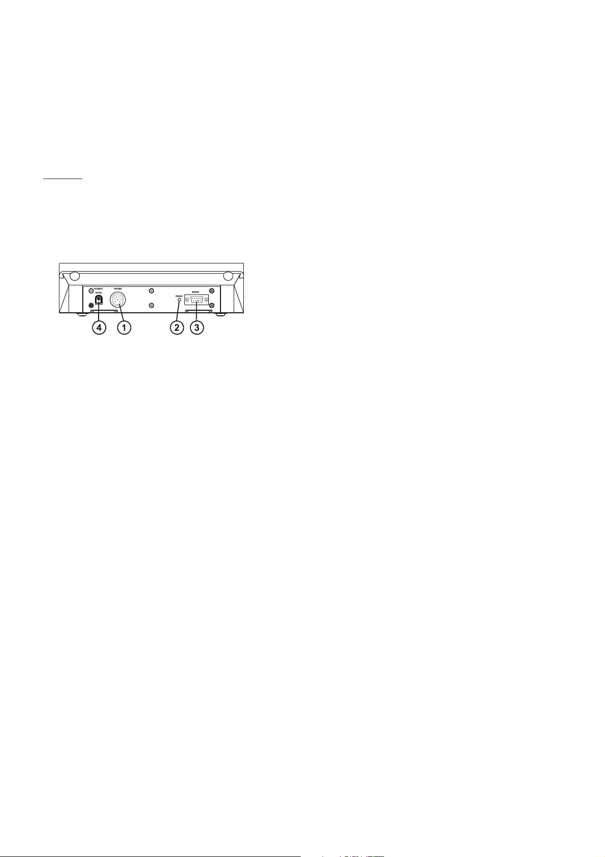
Rear Panel
1. Socket for D.O. Probe
2. Reset Button
3. RS 232C Connector
4. DC Power Socket (for HI 710005 or HI 710006)
19) etx end
?DM Requests the meter to send the selected lot data memory. The
data is sent in the following order:
1) stx
2) Lot number E.g. “01” for lot No. 1
3) Channel #1 status
E.g. “1” for ppm logging selected in this lot
“0” for ppm logging not selected in this lot
4) Channel #2 status
E.g. “1” for % logging selected in this lot
“0” for % logging not selected in this lot
5) Channel #3 status
E.g. “1” for not used “0” for not used
6) Channel #4 status
E.g. “1” for temperature logging selected in this lot
“0” for temperature logging not selected in this lot
7) begin sample time, min. E.g. “59” for 59 minute
8) begin sample time, hour E.g. “12” for 12 hour
9) begin sample time, day E.g. “09” for 9th day
10) begin sample time, month E.g. “09” for September
11) begin sample time, year
E.g. “96” for year 1996
12) logging interval
E.g.“0” for 1 second
“1” for 15 seconds
“2” for 30 seconds
“3” for 1 minu
“4” for 5 minutes
“5” for 30 minutes
“6” for 60 minutes
“7” for 120 minutes
“8” for 180 minutes
13) Total number of samples per lot
E.g. “1234” for total no. of samples: 1234.
14) Logged data in signed integer, repeat sending in logged
channel sequence
6
35
Page 7

8) ... Repeat from 2 to 7 for the next available lot No.
9) etx
?VM Requests the meter to send the selected lot status. The data is
sent in the following order:
1) stx
2) Lot number E.g. “01” for lot No. 1
3) Total number of samples per lot
E.g. “1234” for total no. of samples: 1234.
4) Channel #1 status
E.g. “1” for ppm logging selected in this lot
“0” for ppm logging not selected in this lot
5) Channel #2 status
E.g. “1” for % logging selected in this lot
“0” for % logging not selected in this lot
6) Channel #3 status
E.g. “1” for not used “0” for not used
7) Channel #4 status
E.g. “1” for temperature logging selected in this lot
“0” for temperature logging not selected in this lot
8) Begin sample time, min. E.g. “59” for 59 minutes
9) Begin sample time, hour. E.g. “12” for 12 hours
10) Begin sample time, day. E.g. “09” for the 9th day
11) Begin sample time, month. E.g. “09” for September
12) Begin sample time, year. E.g. “96” for year 1996
13) Logging interval. E.g. “0” for 1 second
“1” for 15 seconds
“2” for 30 seconds
“3” for 1 minute
“4” for 5 minutes
“5” for 30 minutes
“6” for 60 minutes
“7” for 120 minutes
“8” for 180 minutes
14) last sample time, min. E.g. “59” for 59 minute
15) last sample time, hour. E.g. “12” for 12 hour
16) last sample time, day. E.g. “09” for 9th day
17) last sample time, month. E.g. “09” for September
18) last sample time, year. E.g. “96” for year 1996
SPECIFICATIONS OF HI 2400
Ran ge D.O. ppm
D.O. %
Temp. ºC
Resolution D.O. ppm
D.O. %
Temp. ºC
Accuracy D.O.
Temp. ºC
Typical EMC Deviation D.O.
Temp. ºC
Calibration D.O.
Temp. ºC
Altitude Compensation
Resolution
Salinity Compensation
Resolution
Temperature Compensation
Probe
single or double point at 0%
(HI 7040) and 100% (in air)
0.00 to 45.00
0.0 to 300.0
0.0 to 50.0
0.01
0.1
0.1
±1.5% of full scale
±0 . 5
±1.5% of full scale
±0 . 5
single point or double point
at 0.0ºC and/or 50.0ºC
0 to 4,000 m (13,120')
100 m (328')
0 to 40 g/l
1 g/l
0.0 to 50.0ºC
(32 to 122ºF)
HI 76407/2 with
2 meters (6.7") cable
1, 15, 30 seconds
34
7
Page 8

Commands requiring an answer:
Environment 0 to 50ºC (32 to 122ºF);
95% RH
Dimensions 240x182x74 mm
(9.4x7. 1x2. 9")
Wei ght 1.2 kg (2.7 lb.)
Response time The response time is approximately 20 seconds for a
95% reading at a constant temperature of 25ºC.
The response time for low oxygen readings or at low temperature is
approximately 40 seconds. Allow more time to obtain more accurate
readi ngs.l
LCD FUNCTIONAL DESCRIPTION
PRIMARY DISPLAY
SECONDARY DISPLAY
OPERATIONAL GUIDE
POWER CONNECTION
Plug the 12 VDC adapter into the meter.
HI 2400 uses an EEPROM to retain the D.O. calibration and temperature
calibration as well as the serial communication setting. The instrument will
store the respective data after a calibration or serial communication setting,
even when it is not pluggedin.
DO? Causes the meter to send the D.O. (% or ppm will depend on the
meter setting). If the reading is out of range “Err 1” is sent.
TM? Causes the meter to send the temperature value. If the reading
is out of range “Err 3” is sent.
DA? Requests the meter to send the date
E.g. “022896” for 28th Feb. 96
TI? Requests the meter to send the time.
E.g.
“233001” for 23:30 hr, 1 sec. as interval
“233002” for 23:30 hr, 15 sec. as interval
“233003” for 23:30 hr, 30 sec. as interval
“233004” for 23:30 hr, 1 min. as interval
“233005” for 23:30 hr, 5 min. as interval
“233006” for 23:30 hr, 30 min. as interval
“233007” for 23:30 hr, 60 min. as interval
“233008” for 23:30 hr, 120 min. as interval
“233009” for 23:30 hr, 180 min. as interval
?ML Requests the meter to send the available lot number collected in
memory. The transmission begins with <STX> and terminates
with <ETX>. The data are sent in the following order:
1) stx
2) Lot number
E.g. “01” for lot No. 1
3) Total number of samples per lot
E.g. “1234” for total no. of samples: 1234.
4) Channel #1 status
E.g. “1” for ppm logging selected in this lot
“0” for ppm logging not selected in this lot
5) Channel #2 status
E.g. “1” for % logging selected in this lot
“0” for % logging not selected in this lot
6) Channel #3 status
E.g. “1” for not used “0” for not used
7) Channel #4 status
E.g. “1” for temperature logging selected in this lot
“0” for temperature logging not selected in this lot
8
33
Page 9

Shipping
F
ADDITIONAL INFORMATION
If you are not using Hanna Instruments HI 92000 application software,
please find below some additional information to help your connection to the
PC.
SENDING COMMANDS FROM PC
With terminal programs such as Telix® and Windows Terminal®, it is possible
to remotely control your HI 2400. Use HI 920010 cable to connect the meter
to the PC, start the terminal program and set the communication options as
follows: 8, N, 1, no flow control.
Command Types
To send a command to the D.O. meter the scheme is:
<DLE> <command> <CR>
This line makes the computer send a Data Link Escape character, the command expressed as a number or a 3-character sequence and a CR character.
Note: Windows Terminal® and all the other terminal programs that support
the ANSI escape sequence, represent the DLE character by the string
‘^P’ and the CR character by the string ‘^M’. E.g. the line
‘^PPPM^M’ sets the range to ppm.
Commands not requiring an answer from the meter:
PPM sets the range to ppm D.O.
PER sets the range to % D.O.
PROBE CONNECTION & PREPARATION
To prepare the instrument for use, connect the D.O. probe to the meter
securely by aligning the pins with the socket located on the back of the meter,
pushing the plug in and tightening the threaded ring.
Probes shipped from Hanna Instruments are dry. To hydrate the probe and
prepare it for use, connect it to the meter and proceed as follows:
1. Remove the red and black plastic cap. This cap is
for shipping purposes and can be thrown away.
cap
2. Wet the sensor by soaking the bottom 2½ cm (1")
of the probe in electrolyte (HI 7041S) for 5 minutes.
black
3. Rinse the membrane cap (HI 76407A supplied in
the kit with the meter) with electrolyte solution
red
while shaking it gently. Refill with clean electrolyte
solution.
4. Gently tap the sides of the membrane cap
with your finger tip to ensure that no air
bubbles remain trapped. To avoid damaging the membrane, do not tap the mem-
ILL FIRST
brane directly on the bottom.
5. Make sure that the rubber O-ring sits prop-
THEN TAP
erly inside the membrane cap.
6. With the sensor facing down, slowly screw
the cap clockwise. Some electrolyte will overflow.
THEN SCREW
BACK ON
When not in use and during polarization (see page 10),
use the protective transparent cap supplied in the kit with
the meter.
TELIX® is registered Trademark of “Deltacomm”
Windows Terminal® are registered Trademark of “Microsoft Co.”
32
9
Page 10

TURNING THE METER ON
To switch the meter on, press the ON/OFF switch key
and leave the probe in the auto-conditioning (polarization) mode before proceeding. After approximately
5 minutes, the instrument can be calibrated (see
page 12).
If the probe is disconnected, the meter will display “----”.
This also indicates the possibility of a broken probe cable.
PROBE POLARIZATION
The probe is under polarization with a fixed voltage of approximately 800 mV.
Probe polarization is essential for stable measurements with the same recur-
ring degree of accuracy.
With the probe properly polarized, oxygen is continually “consumed” when it
passes through the sensitive diaphragm and dissolves in the electrolyte solution contained in the probe.
If polarization is interrupted, the electrolyte solution continues to be enriched
with oxygen until it reaches an equilibrium with the surrounding solution.
Whenever measurements are taken with a non-polarized probe, the oxygen
level revealed is both that of the tested solution as well as that present in the
electrolyte solution. This reading is incorrect.
The calibration of this instrument is very simple.
Before proceeding with the calibration, make sure the probe is ready for
measurements (see page 9), i.e. the membrane cap is filled with electrolyte
and the probe is connected to the meter and properly polarized.
For an accurate calibration, it is recommended to wait at least 15 minutes to
ensure precise conditioning of the probe.
Keep the protective cap on during the polarization time and remove it for the
calibration and the measurements.
Follow the calibration procedure on page 12.
The Platinum cathode (#8 in the Functional Descripti on page 4)
should always be bright and untarnished. If it is tarnished or stained,
the cathode should be cleaned. You can use a clean lint-free cardboard
or cloth. Rub the cathode very gently side to side 4-5 times. This will
be enough to polish and remove any stains without damaging the
platinum tip. Afterwards, rinse the probe with deionized or distilled
water and install a new membrane cap using fresh electrolyte and
follow the steps above. Re-calibrate the instrument.
Important
In order to have accurate and stable measurements, it is important
that the surface of the membrane is in perfect condition. This semipermeable membrane isolates the sensor elements from the environment
but allows oxygen to enter. If any dirt is observed on the membrane,
rinse carefully with distilled or deionized water. If any imperfections still
exist, or any damage is evident (such as wrinkles or tears-holes), the
membrane should be replaced.
Make sure that the O-Ring sits properly in the membrane cap.
10
31
Page 11

PROBE & MEMBRANE MAINTENANCE
The oxygen probe body is made of reinforced plastic for maximum durability.
A thermistor temperature sensor provides temperature measurements of the
sample. Use the protective probe cap when not in use.
To replace the membrane or refill with electrolyte, proceed as follows:
• Remove the protective cap by gently twisting
and pulling it off the body of the probe (see
fig. 1).
• Unscrew the membrane cap by turning it counterclockwise (see fig.2).
• Wet the sensor by soaking the bottom 2½
cm (1") of the probe in electrolyte (HI 7041S)
for 5 minutes.
• Rinse the new membrane cap (HI 76407A)
supplied with the meter with electrolyte solution while shaking it gently. Refill with clean
electrolyte solution.
• Gently tap the sides of the membrane cap
with your finger tip to ensure that no air
bubbles remain trapped. Do not directly tap
the bottom with your finger as this will damage the membrane.
• Make sure that the rubber O-ringsits properly inside the membrane cap.
• With the sensor facing down, slowly screw the
membrane cap clockwise. Some electrolyte will
overflow.
TWIST
AND
PULL
fig. 1
D.O. MEASUREMENTS (in ppm or %)
Make sure the meter has been calibrated (see page 12) and the protective cap
has been removed.
Salinity and Altitude compensation
If the sample contains significant concentration of salinity or if you are performing measurements at an altitude different from sea level, the readout values
must be corrected, taking into account the lower degree of oxygen solubility in
these situations as explained on pages 18-20.
Remember to set the altitude and/or the salinity before taking any D.O.
measurements. The meter will automatically compensate for these factors.
Taking measurements
Immerse the tip of the probe in the sample to be
tested. Make sure the temperature sensor is also
immersed.
Press the RANGE key to display D.O. measurements. Allow approximately one minute for the
meter to stabilize and read the ppm value of
Dissolved Oxygen on the display.
Press the RANGE key to change the reading from ppm to % and vice-versa.
UNSCREW
fig. 2
For accurate Dissolved Oxygen measurements, a water movement of 0.3 m/sec
is required at a minimum. This is to ensure that the oxygen-depleted membrane surface is constantly replenished. A moving stream will provide adequate circulation.
30
11
Page 12

The use of a magnetic stirrer to ensure a certain velocity of the fluid is
recommended.
Always allow a few minutes for thermal equilibrium to occur
between the probe and the measurement sample.
TAKING TEMPERATURE MEASUREMENTS
The probe has a built-in temperature sensor.
The measured temperature is indicated on the secondary display.
Allow the probe to reach thermal equilibrium before taking any measurement.
Reaching thermal equilibrium can take several minutes. The greater the
difference between the temperature at which the probe was stored and the
temperature of the sample, the longer the time will be.
If “----” is displayed, it indicates that the D.O. probe is not properly connected
or the temperature is out of range. This also indicates the possibility of a
broken probe cable.
D.O. CALIBRATION
For greatest accuracy, it is recommended that the instrument is calibrated
frequently.
The standard calibration program of the meter is prepared for 2 (maximum)
values: 0.0% (zero calibration) and 100.0% (slope calibration).
The next logging will start from page 16.
INTERFACE WITH PC
Data transmission from the instrument to a PC is now much easier with the
new HI 92000 Windows® compatible software (optional).
User friendly, HI 92000 offers a variety of features and has on line help to
support you throughout all situations.
HI 92000 allows you to use the powerful means of the most popular spread
sheet programs (e.g. Excel©, Lotus 1-2-3©). Simply run your favorite spread
sheet and open the file downloaded by HI 92000. It is then possible to make
any elaboration available with your software (e.g. graphics, statistical analysis).
To install HI 92000 you need a 3.5" drive and few minutes to follow the
instructions conveniently printed on the disk’s label.
To connect your HI 2400 to a PC, use HI9 20010, available through your
Hanna Dealer. Make sure that your meter is switched off and plug the
connectors, one into the meter RS232C connector, the other into the serial port
of your PC.
Note: Cables different from the HI 920010 may use a different configuration.
In such case any communication between the meter and the PC is not
possible.
Windows® and Windows Terminal
Excel© Copyright of “Microsoft Co.”
Lotus 1-2-3© Copyright of “Lotus Co.”
12
®
are registered Trademark of “Microsoft Co.”
29
Page 13

Note: If the ON/OFF switch is pressed while
logging, the meter will stop the logging
first and then will turn off.
MEMORY ORGANIZATION
The meter is equipped with a stability indicator and the user will be guided
step by step with symbols on the display during the D.O. calibration. This will
make the calibration a simple and error-free procedure.
The zero calibration of the HI 2400 is very stable, therefore this procedure
needs only to be performed whenever the probe or the membrane is
replaced.
However, because the slope calibration is more critical, it is recommended
to perform this procedure every week.
The memory used for storing the logged data is divided into 16 pages. The
capacity of each page is 500 samples. It starts to log from page 16 downwards
until 1 and then 16 again, overwriting the previous data. However, when
this happens the LCD will show page “0”, indicating overwriting has occurred.
Each time a new logging period starts, it automatically starts from a new
page.
When the samples collected for a single lot are more than the limit (8000
samples) the meter will stop logging automatically.
TO CLEAR LOGGED DATA
The entire logged data can be cleared by pressing the ON/OFF switch and the
LOG key simultaneously.
INITIAL PREPARATION
• Pour small quantities of HI 7040 Zero Oxygen
solution into a beaker. If possible, use a plastic
beaker to minimize any EMC interferences.
• Make sure the probe is ready for measurements
(see initial preparation at page 9), i.e. the membrane is filled with electrolyte and the probe is
connected to the meter.
• Switch the meter on by pressing the ON/OFF switch.
• For an accurate calibration, it is recommended to
wait for at least 15 minutes to ensure precise conditioning of the probe.
• Remove the protective cap from the D.O. probe.
• Set the appropriate altitude factor (see page 19).
Make sure the salinity factor is set to zero (see page
18).
ZERO CALIBRATION
• Dip the probe into HI 7040 zero oxygen solution
and stir gently for 2-3 minutes.
HI 7040
HI 7040
The choice has to be confirmed by pressing the CFM key.
28
13
Page 14

• Press the CAL key and the “~” indicator will blink until the reading is
stable.
• As soon as the reading is stable, the “CFM” indicator will start blinking.
Press the CFM key to confirm the “0.0%” D.O. reading.
• If the reading is not close to the selected value,“WRONG “ and
“WRONG ” will blink alternatively.
• If the reading is within the margins (±15%), the meter stores the value
(and adjusts the offset point). The meter will then proceed with the next
calibration point.
• Press the CAL key and the calibration process
is ended with only the zero of the calibrated
meter. For a two-point calibration do not press
the CAL key and follow the procedure below.
During logging, you can check some information about the logged data.
Press the LOG key to display the current sample number (the number of
readings that have been stored in the current lot).
Press the RANGE key to display the measurement reading during the logging
mode.
Press the LOG key again and the primary LCD will show the current lot
number and the secondary LCD will display the current page number.
TO STOP LOGGING
To stop logging press the LOG and then CAL key.
SLOPE CALIBRATION
It is suggested to perform the slope calibration in air.
• Rinse the probe in clean water to remove any residual zero oxygen
solution.
Note: If you did not perform the zero calibration procedure, press the CAL key
and then the UP key to select the 100% calibration value.
14
The display will show the next lot number.
27
Page 15

TEMPERATURE COMPENSATION
The D.O. probe has a built-in sensor for temperature so that the D.O.
readings are automatically compensated for temperature effects.
LOGGING FUNCTION
This function allows the user to log D.O. (in ppm or %) together with the
temperature automatically for long periods of time. All logged data can be
stored into a PC through the RS232C port.
The lot number goes from 1 to 99 and then back to #1. The maximum
capacity per lot is 8000 samples.
Set the appropriate logging interval (see page12). Select between 1, 15, 30
seconds or 1, 5, 30, 60, 120, 180 minutes.
Press the RANGE key first (to select D.O. readings in ppm or in %), then press the LOG and
then CAL key to enter the logging mode.
• Dry the probe tip and allow a few minutes for the LCD readout to stabilize.
The “~” indicator will blink until the reading is stable.
As soon as the reading is stable, the “CFM” indicator will start blinking. Press
the CFM key to confirm the “100.0%” D.O. reading.
• If the reading is not close to the selected value,“WRONG “ and
“WRONG ” will blink alternatively.
Once in the logging mode, the interval cannot be changed.
Exit the logging mode first (by pressing the LOG and then CAL key) before
setting a new interval.
• If the reading is within the margins (±15%), the meter stores the value
(and adjusts the slope point). The calibration is ended and the meter will
then revert to the normal measurement mode.
Note: HI 2400 has automatic buffer recognition function. Press the UP or
DOWN arrow keys to select the desired calibration value, but if these
keys are pressed, the automatic buffer recognition function is disabled.
1526
Page 16

Press the CAL key at any time to exit the calibration
mode.
TEMPERATURE CALIBRATION
Each meter has been factory calibrated for the temperature with the D.O.
probe supplied and is ready for measurements.
The D.O. probes are interchangeable and no temperature calibration is
needed.
If the temperature measurements are not accurate, the temperature recalibration should be carried out.
For an accurate re-calibration, contact your nearest Hanna Service Center or
follow the procedure below (for technical personnel only).
INITIAL PREPARATION
• Prepare a beaker containing ice(at 0.0°C/32°F) and water and another
one containing hot water (at a temperature of 50.0°C/122°F). Place insulation
material around the container to minimize temperature changes.
• Use a ChecktempC or a calibrated thermometer with a resolution of 0.1°C as a
reference thermometer.
Setting the Buzzer Status
In the View Settings Mode, press the UP or DOWN arrow keys to display the
buzzer status; ON is the factory setting.
Press the CAL key to enter the change setting mode, the buzzer status will
start blinking.
Select the buzzer status (ON or CLR) by pressing the UP or DOWN arrow keys.
PROCEDURE
• Switch the meter on while pressing the CAL key. The “CAL” indicator will
be lit. The secondary LCD section will show “0.0°C”.
16 25
Press the CFM key to confirm the buzzer status.
RESET BUTTON
The RESET button is used when the instrument displays erroneous messages
due to strong electrical interference or when the instrument’s power supply
was disconnected before the meter was switched off.
It is necessary to press the RESET button and restart the entire operation.
Calibration points should remain memorized. It is recommended to verify
calibration before proceeding.
Page 17

The following baud rate can be selected through the UP or DOWN arrow keys:
150, 300, 600, 1200 (factory setting), 2400, 4800 and 9600.
Press the CFM key to confirm the baud rate setting.
Setting the Command Prefix
In the View Settings Mode, press the UP or DOWN arrow keys to display the
command prefix; 16 is the factory setting.
Press the CAL key to enter the change setting mode, the command prefix will
start blinking.
Select a different command prefix (between 0 to 47 decimal) by pressing the
UP or DOWN arrow keys.
• Immerse the D.O. probe in the vessel
with the ice and water.
• Wait for about 30 seconds until the
“CFM” indicator starts blinking. Press
the CFM key. The secondary LCD section will show “50.0°C”.
• Immerse the D.O. probe in the vessel with
hot water.
• Wait for about 30 seconds until the “CFM”
indicator starts blinking. Press the CFM key.
• The temperature calibration procedure is
now completed.
SETUP
Press the CFM key to confirm the command prefix
setting.
Note: The Command Prefix does not have to be changed using HI 92000
Hanna software.
Setup is used to view or change the instrument parameters. To enter in View
Settings press the SETUP key when the meter is in measurement mode.
View Setttings
By pressing the UP or DOWN arrow keys you can view the setting values for
the following parameters:
1724
Page 18

• Salinity Compensation
• Altitude Compensation
• Log Interval
• Time
• Date
• Baud Rate
• Command Prefix
• Buzzer Status
If you press the SETUP key anytime in theView Settings Mode the device will
enter the measurement mode.
CHANGE SETTINGS
Press the CFM key, the day starts blinking.
Use the UP or DOWN arrow keys to select the day.
To modify a parameter from the setup menu press the CAL key. You will enter
the Change Settings Mode.
If you don’t want to change the parameter press the CAL key. The setting
value will revert to the previously memorized value and the device will return
to the View Settings.
Setting the Salinity Compensation
In the View Settings Mode, press the UP or DOWN arrow keys to display the
salinity factor.
Press CAL to enter the change setting mode, the salinity factor will start
blinking.
Use the UP and DOWN arrow keys to set the
salinity between 0 and 40 g/l.
Press the CFM key to confirm the salinity factor.
Press the CFM key and the year on the secondary LCD will blink.
Use the UP or DOWN arrow keys to select the year.
Press the CFM key to confirm the date setting.
Setting the Baud Rate
In the View Settings Mode, press the UP or DOWN arrow keys to display the
baud rate.
The transmission speed (baud rate) of your HI2400 and of the external device
must be the same.
Press the CAL key to enter the change setting mode, the baud rate will start
blinking.
18 23
Page 19

4
0
6
2
8
4
0
Use the UP and DOWN arrow keys to set the hour.
Press the CFM key and the minutes will start blinking.
Use the UP or DOWN arrow keys to select the minutes.
Press the CFM key to confirm the time setting.
Setting the Date
In the View Settings Mode, press the UP or DOWN arrow keys to display the
date. The month and the day will be displayed on the primary LCD, the year
on the secondary one.
Press the CAL key to enter the change setting mode, the month will start
blinking.
The salinity affects the D.O. concentration, decreasing its value. Below is a
table showing the maximum solubility of oxygen at various temperatures and
salinity levels.
S alinity (g/l) at Sea L eve l
ºC
0 g/l 10 g/l 20 g/l 30 g/l 35 g/l
0 14.6 13.6 12.7 11.9 11.5 32.0
2 13.8 12.9 12.1 11.3 10.9 36.5
4 13.1 12.3 11.5 10.7 10.4 39.2
6 12.4 11.7 10.9 10.2 9.9 42.8
8 11.8 11.1 10.4 9.8 9.4 46.4
10 11.3 10.6 9.9 9.3 9.0 50.0
12 10.8 10.1 9.5 8.9 8.6 53.6
14 10.3 9.7 9.1 8.6 8.3 57.2
16 9.9 9.3 8.7 8.2 8.0 60.8
18 9.5 8.9 8.4 7.9 7.6 64.4
20 9.1 8.5 8.0 7.6 7.4 68.0
22 8.7 8.2 7.8 7.3 7.1 71.6
24 8.4 7.9 7.5 7.1 6.9 75.2
26 8.1 7.6 7.2 6.8 6.6 78.8
28 7.8 7.4 7.0 6.6 6.4 82.4
30 7.5 7.1 6.8 6.4 6.2 86.0
32 7.3 6.9 6.5 6.2 6.0 89.6
34 7.1 6.7 6.3 6.0 5.9 93.2
36 6.8 6.5 6.1 5.8 5.7 96.8
38 6.6 6.3 6.0 5.7 5.5 100.
40 6.4 6.1 5.8 5.5 5.4 104.
42 6.2 5.9 5.6 5.3 5.2 107.
44 6.0 5.8 5.5 5.2 5.1 111.
46 5.9 5.6 5.3 5.1 5.0 114.
48 5.7 5.5 5.2 4.9 4.9 118.
50 5.5 5.3 5.1 4.8 4.7 122.
ºF
Setting the Altitude Compensation
In the View Settings Mode, press the UP or DOWN arrow keys to display the
altitude factor.
Press the CAL key to enter the change setting mode, the altitude factor will
start blinking.
Use the UP or DOWN arrow keys to select the month.
Use the UP and the DOWN arrow keys to set the altitude between 0 and
4000 m, in steps of 100 m (1 meter = 3.28 feet).
1922
Page 20

ºC
300m600m900m1200m1500m1800m2100m2400m2700m3000m3300m3600m4000
0 m
0 14 .6 14.1 13.6 13. 2 1 2.7 12. 3 11 .8 10. 9 10.2 9.4 8 .7 8. 1 7.6 6.6 32.0
2 13.8 13.3 12.9 12.4 12.0 11.6 11.2 10.3 9.6 8.9 8.2 7.7 7.1 6.3 35.6
4 13.1 12.7 12.2 11.9 11.4 11.0 10.6 9.8 9.1 8.5 7.8 7.3 6.7 6.0 39.2
6 12 .4 12.0 11.6 11. 2 1 0.8 10. 4 10.1 9.3 8.6 8.0 7.4 6.9 6.4 5.7 42.8
8 11 .8 11.4 11.0 10. 6 1 0.3 9.9 9 .6 8.8 8.2 7.6 7.1 6.5 6.1 5.4 46.4
Altitude, Meters above S ea L evel
m
Press the CFM key to confirm the altitude factor.
ºF
The altitude affects D.O. concentration decreasing its value. The table on the
previous page reports the maximum oxygen solubility at various temperatures
and altitudes.
Setting the Logging Interval
10 11.3 10. 9 10.5 10.2 9.8 9 .5 9.2 8.4 7.8 7.3 6.8 6.3 5. 8 5. 1 5 0.0
12 10.8 10.4 10.1 9.7 9.4 9.1 8.8 8.1 7.5 7.0 6.4 6.0 5.6 4.9 53.6
14 10.3 9.9 9.6 9. 3 9. 0 8.7 8.3 7.7 7. 2 6.6 6.2 5.7 5.3 4.7 57.2
16 9.9 9.7 9.2 8.9 8.6 8.3 8.0 7.4 6.9 6.4 5.9 5.5 5.1 4.5 60.8
18 9.5 9.2 8.7 8.6 8.3 8.0 7.7 7.1 6.6 6.1 5.7 5.3 4.9 4.3 64.4
20 9.1 8.8 8.5 8.2 7.9 7.7 7.4 6. 8 6.3 5.9 5.5 5.1 4.7 4.1 68.0
22 8.7 8.4 8. 1 7.8 7.7 7.3 7. 1 6.5 6.0 5.6 5.3 4.9 4.5 4.0 71.6
24 8.4 8.1 7.8 7.5 7.3 7.1 6.8 6.3 5.8 5.5 5.1 4.7 4.4 3.8 75.2
26 8.1 7.8 7.5 7.3 7.0 6.8 6.6 6. 0 5.7 5.2 4.8 4. 5 4. 2 3.7 7 8.8
28 7.8 7.5 7.3 7.0 6.8 6.6 6.3 5.9 5.4 5.0 4.7 4.3 4.0 3.6 82.4
30 7 .5 7.2 7.0 6.8 6.5 6.3 6. 1 5. 7 5.2 4.9 4.6 4.2 3. 9 3.5 86. 0
32 7.3 7.1 6.8 6.6 6.4 6.1 5.9 5.5 5.1 4.7 4.4 4.1 3.8 3.3 89.6
34 7.1 6.9 6.6 6.4 6.2 6.0 5.8 5. 3 4.9 4.6 4.2 3.9 3. 7 3.2 93. 2
36 6.8 6.6 6.3 6.1 5.9 5.7 5.5 5.1 4.8 4.5 4.1 3.8 3.5 3.1 96.8
38 6.6 6.4 6.2 5.9 5.7 5.6 5.4 5. 0 4.6 4.3 4.0 3.7 3.5 3.0 100.4
In the View Settings Mode, press the UP or DOWN arrow keys to display the
logging interval.
Press the CAL key to enter the change setting mode, the logging interval will
start blinking.
Use the UP and the DOWN arrow keys to set the logging interval between 1,
15, 30 seconds, or 1, 2, 5, 15, 30, 60, 120, 180
minutes.
Press the CFM key to confirm the setting.
Setting the Time
In the View Settings Mode, press the UP or DOWN arrow keys to display the
time.
Press the CAL key to enter the change setting mode, the hour will start
blinking.
20 21
 Loading...