

Page 1
Instruction Manual
C
HI2300
Microprocessor Conductivity Meter
ALT FunctionsFunctions
TC
ATC
ALT
LOCK
SETUP
GLP
RANGE
CFM
CAL
CALT
Display TC Factor
TC
View Calibration
Data
GLP
SETUP
Enter Setup Mode
Start Temperature
Calibration
CALT
Temperature
Compensation
ATC
Confirm Value
CFM
Change Value
/
Lock Current Range
LOCK
Start Calibration
CAL
Select Measurement
Range
RANGE
HI 2300
Auto-ranging
Microprocessor
EC/TDS/NaCl/ºC
Bench Meter
www.hannainst.com
1
Page 2

Dear Customer,
Thank you for choosing a Hanna Instruments product.
Please read this instruction manual carefully before using the instrument.
This manual will provide you with the necessary information for correct use of
the instrument, as well as a precise idea of its versatility.
If you need additional technical information, do not hesitate to e-mail us at
tech@hannainst.com or turn to the back cover for our worldwide contact list.
This instrument is in compliance with directives.
WARRANTY
HI 2300 is guaranteed for two years against defects in workmanship and
materials when used for their intended purpose and maintained according to
instructions. Electrodes and probes are guaranteed for six months. This warranty
is limited to repair or replacement free of charge.
Damage due to accidents, misuse, tampering or lack of prescribed maintenance
is not covered.
If service is required, contact the dealer from whom you purchased the
instrument. If under warranty, report the model number, date of purchase,
serial number and the nature of the problem. If the repair is not covered by
the warranty, you will be notified of the charges incurred. If the instrument is
to be returned to Hanna Instruments, first obtain a Returned Goods
Authorization number from the Technical Service department and then send
it with shipping costs prepaid. When shipping any instrument, make sure it
is properly packaged for complete protection.
TABLE OF CONTENTS
WARRANTY ..................................................................................................... 2
PRELIMINARY EXAMINATION .............................................................................. 3
GENERAL DESCRIPTION .................................................................................... 3
FUNCTIONAL DESCRIPTION ................................................................................ 4
SPECIFICATIONS ............................................................................................... 5
OPERATIONAL GUIDE ........................................................................................ 7
AUTORANGING ................................................................................................ 8
TEMPERATURE COMPENSATION ......................................................................... 8
EC/TDS CALIBRATION ....................................................................................... 9
NaCl CALIBRATION ......................................................................................... 10
TEMPERATURE CALIBRATION (for technical personnel only) .................................. 12
TEMPERATURE ADJUSTMENT .......................................................................... 12
CONDUCTIVITY VERSUS TEMPERATURE CHART ................................................. 13
SETUP .......................................................................................................... 14
GOOD LABORATORY PRACTICE ........................................................................ 15
DATA TRANSFER TO PC ................................................................................... 17
PROBE MAINTENANCE .................................................................................... 18
ACCESSORIES ................................................................................................ 18
2
Page 3

PRELIMINARY EXAMINATION
Remove the instrument from the packing material and examine it carefully to
make sure that no damage has occurred during shipping. If there is any
damage, notify your Dealer or the nearest Hanna Customer Service Center.
Each instrument is supplied with:
• HI 76310 Conductivity / TDS probe
• 12V Power Adapter
• Instruction Manual
Note: Save all packing material until you are sure that the instrument
functions correctly. All defective items must be returned in the original
packing with the supplied accessories.
GENERAL DESCRIPTION
The HANNA HI 2300 is a bench microprocessor-based Conductivity/TDS/
NaCl/Temperature meter.
The autoranging feature of the EC and TDS ranges automatically sets the
instrument to the scale with the highest possible resolution.
The conductivity measurements are manually or automatically compensated
for temperature effect, with the temperature sensor inside the conductivity
probe. It is also possible to disable the temperature compensation and measure the actual conductivity.
The temperature coefficient is user selectable.
The instrument is equipped with a stability indicator. With this feature the
user will always know when to record a measurement.
HI 2300 includes also GLP capability and data transfer to a computer
through a RS232 port.
In addition, the meter allows the user to enter an ID code to uniquely identify
the instrument.
Hanna Instruments reserves the right to modify the design,
construction and appearance of its products without advance notice.
3
Page 4
11
CAL
CFM
ppm
BUF
g / l
%
NaCl C
HI 2300
Microprocessor Conductivity Meter
ALT FunctionsFunctions
TC
ATC
ALT
LOCK
SETUP
GLP
RANGE
CFM
CAL
CALT
Display TC Factor
TC
View Calibration
Data
GLP
SETUP
Enter Setup Mode
Start Temperature
Calibration
CALT
Temperature
Compensation
ATC
Confirm Value
CFM
Change Value
/
Lock Current Range
LOCK
Start Calibration
CAL
Select Measurement
Range
RANGE
RS232
PROBEPOWER
12VDC
Front Panel
Primary LCD
Secondary LCD
1
2
8
4
6
3
12
Rear Panel
9
10
5
7
13
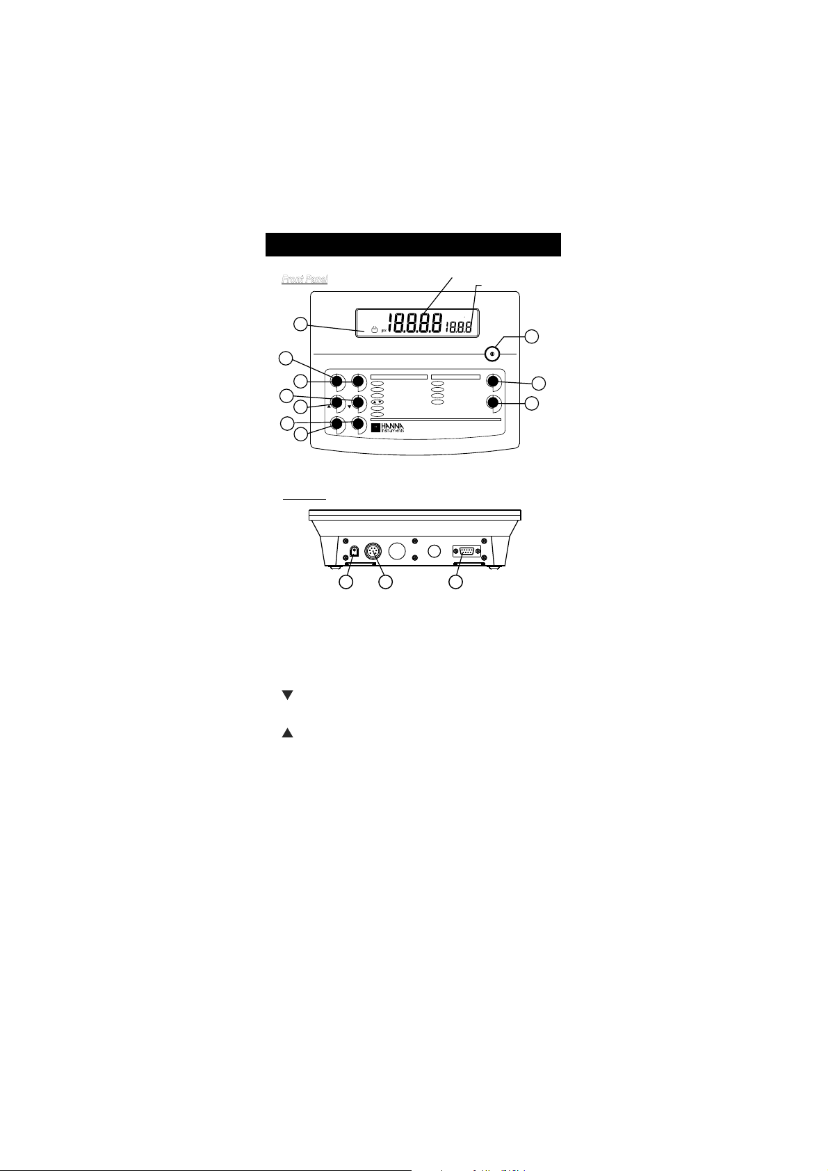
FUNCTIONAL DESCRIPTION
1) Liquid Crystal Display (LCD).
2) CAL key, to enter/exit calibration mode.
CALT key (alternate function), to enter temperature calibration mode.
3) CFM key, to confirm different values.
4) key, to manually decrease temperature value or other parameters.
SETUP key (alternate function), to enter/exit SETUP mode.
5) key, to manually increase temperature value or other parameters.
GLP key (alternate function), to display Good Laboratory Practice information.
6) ATC key, to select temperature compensation mode.
TC key (alternate function), to view the temperature coefficient value.
7) ALT key, to select alternate key function.
8) LOCK key, to freeze current range on the LCD.
9) RANGE key, to select the measurement unit or to switch the focused data.
10) ON/OFF switch.
11) Power supply socket.
12) Probe connector.
13) RS232 serial communication connector.
4
Page 5
SPECIFICATIONS
EGNAR
CE
99.92ot00.0 µ mc/S
9.992ot0.03 µ mc/S
9992ot003 µ mc/S
mc/Sm99.92ot00.3
mc/Sm0.002ot0.03
*)CElautca(mc/Sm0.005otpu
SDT
)mpp(L/gm99.41ot00.0
)mpp(L/gm9.941ot0.51
)mpp(L/gm9941ot051
)tpp(L/g99.41ot05.1
)tpp(L/g0.001ot0.51
*)SDTlautca(L/g0.004otpu
rotcafnoisrevnoc08.0htiw
lCaN %0.004ot0.0
pmeT C°0.021ot9.9–
NOITULOSER
CE
10.0 µ mc/S
1.0 µ mc/S
1 µ mc/S
mc/Sm10.0
mc/Sm1.0
SDT
L/gm10.0
L/gm1.0
L/gm1
L/g10.0
L/g1.0
lCaN %1.0
pmeT C°1.0
YCARUCCA
F°86/C°02@
CE
50.0(±gnidaerfo%1± µ romc/S
)tigid1
SDT
roL/gm30.0(±gnidaerfo%1±
1 )tigid
lCaN gnidaerfo%1±
pmeT C°4.0±
NOITARBILAC
CE
6htiwtniop1,citamotuA
:seulavdeziromem
3141,0.48 µ mc/S
mc/Sm8.111,0.08,88.21,00.5
lCaN
noitarbilac7307IHhtiw,tniop1
noitulos
pmeT
dna23(C°05dna0ta,tniop-2
)F°221
* Actual conductivity (or TDS) is the conductivity (or TDS) value without temperature compensation.
5
Page 6
erutarepmeT
noitasnepmoc
Cº06ot0,launamrocitamotuA
)Fº041ot23(
tneiciffeocerutarepmeT
Cº/%00.6ot00.0morfelbatceleS
)ylnoSDTdnaCE(
rotcafnoisrevnocSDT
08.0ot04.0morfelbatceleS
)05.0:eulavtluafed(
)dedulcni(eborP
lanretni,munitalPgnir-401367IH
rosneserutarepmet
ecafretnIretupmoC detalosi-otpo232SR
ffo-otuA
esu-nonfosetunim5retfa
)delbasidebnac(
ylppusrewoP
retpadarewopcdV21
)dedulcni(
snoisnemiD )”9.2x1.7x4.9(mm47x281x042
thgieW )bl4.2(gK1.1
tnemnorivnE
)Fº221-23(Cº05–0
gnisnednocnon%59HRxam
ytnarraW sraey2
SPECIFICATIONS (cont.)
6
Page 7

OPERATIONAL GUIDE
RS232
PROBEPOWER
12VDC
CAL
CFM
ppm
BUF
g / l
%
NaCl
C
RANGE
C
CONNECTIONS
Plug the 12 VDC adapter into the power supply socket.
Note: This instrument use non volatile memory to retain the calibration
parameters and all the other settings even when unplugged.
Connect the EC/TDS probe to the 7-pin connector. Tighten the threaded ring.
Make sure the probe sleeve is properly inserted, as shown below:
INSTRUMENT START-UP
• Turn the instrument on by pressing the ON/OFF switch.
• All LCD tags are displayed and a beep is generated while the instrument
performs self test.
TAKING MEASUREMENTS
Immerse the probe into the solution to be tested. The sleeve
holes must be completely submerged. Tap the probe repeatedly to remove any air bubbles that may be trapped inside
the sleeve.
If needed, press RANGE repeatedly until the desired range (EC, TDS, NaCl) is
selected on the LCD (displaying µS[mS], ppm[g/L] or %).
Allow for the reading to stabilize. The upper LCD displays the measurement in
the selected range, while the temperature is displayed on the lower LCD.
7
Page 8

Notes:
LOCK
• If the meter displays “----”, the reading is out of range.
• If the stability indicator “~” blinks, the reading is unstable.
• Make sure the meter is calibrated before taking measurements.
• If measurements are taken successively in different samples, for accu-
rate readings it is recommended to rinse the probe thoroughly with
deionized water before immersing it into the samples.
• TDS reading is obtained by multiplying the EC reading by the TDS
factor, which has a default value of 0.50. It is possible to change the
TDS factor in the 0.40 to 0.80 range by entering setup mode and
selecting the “tdS” item (see SETUP for details).
• When the use of an alternate function (SETUP, TC, GLP or CALT) is
requested, press and hold the ALT key first, and then the second key.
AUTORANGING
The EC and TDS scales are autoranging. The meter automatically sets the scale
with the highest possible resolution.
By pressing LOCK, the autoranging feature is disabled and
the current range is frozen on the LCD. “1” tag starts
blinking. To restore the autoranging option press LOCK
again.
Note: Autoranging is automatically restored if the range is changed, if the
setup or calibration modes are entered, or if the meter is turned off and
back on again.
TEMPERATURE COMPENSATION
Three options of compensating temperature are available:
Automatic (Atc): The EC probe has a built-in temperature sensor; the
temperature value is used to automatically compensate the EC/TDS reading
(from –9.9 °C to 120.0 °C), using the selected reference temperature.
Manual (Mtc): The temperature value, shown on the secondary LCD, can be
manually set with the ARROW keys. The compensation is referenced at the
selected reference temperature. The “°C” tag blinks when this option is active.
No Compensation (notc): The temperature value shown on the secondary LCD
is not taken into account. The reading displayed on the primary LCD is the actual
EC or TDS value. The “°C” tag blinks when this option is active.
Note: The default compensation mode is ATC.
8
Page 9

To select the desired option press ATC until the option is
CAL
BUF
ALT TC
CAL
ATC
displayed on the LCD.
If temperature compensation is active, measurements are
compensated using the temperature coefficient (default value
1.90 %/°C).
To change the temperature coefficient, enter the setup mode and select the “tc”
item (See SETUP for details, page 14). The current temperature coefficient can be
quickly viewed by pressing ALT+TC keys. The value is briefly displayed on the
secondary LCD.
• If the temperature reading is out of –9.9 °C - 120.0 °C interval and Atc or
Mtc option is selected, the temperature limit range value will be displayed,
together with the “°C” tag blinking and the instrument will do no
temperature compensation.
EC/TDS CALIBRATION
EC calibration is a one-point procedure. Selectable calibration points are:
0.00 µS, 84.0 µS, 1413 µS, 5.00 mS, 12.88 mS, 80.0 mS, 111.8 mS.
To enter EC calibration, select the EC range and press CAL.
Note: TDS reading is automatically derived from the EC reading and no
specific calibration for TDS is needed. Pressing CAL when TDS range is
selected has no effect.
Rinse the probe with calibration solution or deionized water.
Immerse the probe into the solution. The sleeve holes must be
completely submerged. Tap the probe repeatedly to remove any
air bubbles that may be trapped inside the sleeve.
For zero calibration, just leave the dry probe in the air.
The “BUF” and “CAL” tags are displayed. The primary LCD displays the
uncalibrated EC reading. The secondary LCD displays the buffer value. The
“~” tag blinks.
9
Page 10

Select the desired value with the ARROW keys, if necessary.
CAL
CFM
BUF
OR
CFM
CAL
When the reading is stable, “CFM” tag starts blinking on the LCD, asking for
confirmation. Press CFM to confirm calibration.
The instrument displays the “Stor Good” message and returns to measurement mode.
Notes:
• If the uncalibrated reading is too far from the expected value or the
temperature value is out of 0 – 60 ºC range, calibration is not recognized.
The “CFM” tag does not appear; the “~” and “BUF” tags blink to signal
wrong or contaminated calibration solution. If the temperature value is out
of 0 – 60 ºC range, the “ºC” tag will also be displayed blinking on the LCD.
• For best results choose an EC buffer value close to the sample to be measured.
• In order to minimize any EMC interferences, use plastic beakers.
• The meter uses 1.90 %/°C compensation factor during calibration. If
the setup item “tc” has been set to a different value, when exiting
calibration mode, the displayed value on the upper LCD might be
different from the nominal buffer value.
• It is possible to set the cell constant value directly, without following the
calibration procedure. To set the cell constant enter the setup mode
and select “CEL” (see SETUP for details).
NaCl CALIBRATION
NaCl calibration is a one-point procedure at 100.0% NaCl. Use the
HI 7037L calibration solution (sea water solution) as a 100% NaCl
standard solution.
To enter NaCl calibration select the NaCl range and
press CAL.
Rinse the probe with some of the calibration solution or
deionized water. Immerse the probe into HI 7037L
solution. The sleeve holes must be completely submerged.
Tap the probe repeatedly to remove any air bubbles
that may be trapped inside the sleeve.
10
Page 11

The “BUF” and “CAL” tags are displayed. The primary LCD displays the
CAL
BUF
%
NaCl
CAL
CFM
BUF
%
NaCl
CFM
uncalibrated NaCl reading in percentage. The secondary LCD displays “100”.
When the reading is stable, “CFM” tag starts blinking on the LCD, asking for
confirmation. Press CFM to confirm calibration.
The instrument displays the “Stor Good” message and returns to measurement mode.
Notes:
• If the uncalibrated reading is too far from the expected value, calibra-
tion is not recognized. The “CFM” tag does not appear; the “~” and
“BUF” tags blink to signal wrong or contaminated calibration solution.
• The meter uses 1.90 %/°C compensation factor during calibration. If
the setup item “tc” has been set to a different value, when exiting
calibration mode, the displayed value on the upper LCD might be
different from the nominal buffer value.
11
Page 12

TEMPERATURE CALIBRATION
ALT CALT
CAL
OR
CFM
(for technical personnel only)
The calibration is a 2-point procedure at 0.0 and 50.0 ºC.
• Immerse the probe in a 0 ºC temperature bath.
• Press ALT+CALT keys to enter temperature calibration mode.
• The lower LCD displays “0.0 ºC”, “BUF” and “CAL” tags blinking.
• When the reading is stable, “CFM” tag starts blinking.
• Press CFM to confirm. The lower LCD displays 50.0 ºC.
• Immerse the probe in a 50 ºC temperature bath.
• When the reading is stable, “CFM” tag starts blinking.
• Press CFM to confirm. The meter returns to measurement mode.
TEMPERATURE ADJUSTMENT
The temperature reading can be manually fine-tuned following the next
procedure:
Press ALT + CALT keys to enter temperature
calibration mode.
Press CAL to enter temperature adjustment mode. The
primary and secondary LCD will display the current
temperature reading.
Adjust the temperature reading on the primary
LCD using the ARROW keys. The maximum
adjustment is ±1 °C around current reading.
Press CFM to confirm. The meter returns to measurement
mode and displays the new temperature.
Notes:
• Press ALT + CALT keys to escape without any changes.
• To enter temperature adjustment mode, the probe must be connected
to the instrument.
12
Page 13

CONDUCTIVITY VERSUS
Cº Fº 0307IH
0308IH
)mc/Sµ(
1307IH
1308IH
)mc/Sµ(
3307IH
3308IH
)mc/Sµ(
4307IH
4308IH
)mc/Sµ(
5307IH
5308IH
)mc/Sµ(
9307IH
9308IH
)mc/Sµ(
0
5
01
51
61
71
81
91
02
12
22
32
42
52
62
72
82
92
03
13
23
14
05
95
8.06
6.26
4.46
2.66
86
8.96
6.17
4.37
2.57
77
8.87
6.08
4.28
2.48
68
8.78
0517
0228
0339
08401
02701
05901
09111
03411
07611
01911
05121
09321
04621
08821
03131
07331
02631
07831
02141
07341
677
698
0201
7411
3711
9911
5221
1521
8721
5031
2331
9531
6831
3141
0441
7641
4941
1251
8451
5751
46
56
76
86
07
17
37
47
67
87
97
18
28
48
68
78
98
09
29
49
00384
00535
00695
00456
00276
00586
00896
00317
00427
00047
00257
00567
00387
00008
00318
00038
00948
00368
00288
00009
00456
00147
00238
00529
00449
00369
00289
002001
001201
000401
009501
009701
008901
008111
008311
007511
007711
007911
008121
009321
0672
0813
5163
3604
5514
5424
7334
9244
3254
7164
1174
5084
2094
0005
6905
0915
6825
3835
9745
5755
TEMPERATURE CHART
The conductivity of an aqueous solution is the measure of its ability to carry an
electrical current by means of ionic motion.
The conductivity invariably increases with increasing temperature.
It is affected by the type and number of ions in the solution and by the viscosity
of the solution itself. Both parameters are temperature dependent. The dependency of conductivity on temperature is expressed as a relative change per
Celsius degree at a particular temperature, commonly as percent per ºC.
The following table lists the temperature dependence of the HANNA calibration buffers.
13
Page 14

SETUP
ALT SETUP
OR
CFM
OR
RANGE
CFM
Setup mode allows viewing and modifying the instrument parameters.
To enter setup press ALT+SETUP keys when
the meter is in measurement mode.
“Set” is displayed on the primary LCD.
The secondary LCD displays the code of the current setup item.
Select the desired setup item using the ARROW keys. Press CFM to confirm.
Note: If ALT+SETUP keys are pressed before item confirmation, the meter
exits SETUP mode and returns to measurement mode.
Once the desired setup item has been selected, its current value starts blinking
(if it is a changeable parameter).
Press the ARROW keys to change the value.
Press RANGE. The other item will start blinking (e.g. month in setting up the
correct date).
Press the ARROW keys to change the value.
Press CFM to confirm.
14
Page 15

Note: Press ALT+SETUP keys before confirmation to escape without changing
ALT GLP
the previously set value.
The following table lists the setup items, their valid range of values and the
factory settings (default):
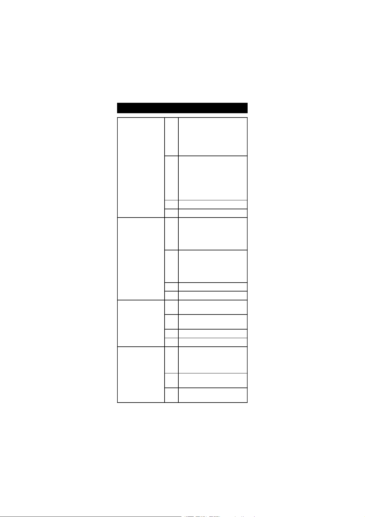
Item Description Valid values Default
tc Temp.compensation coeff. 0.00 to 6.00 %/ºC 1.90
tcE Temp.compensation mode Atc, Mtc, notc Atc
rEF Reference temperature 20.0 ºC, 25.0 ºC 25.0 ºC
tdS TDS factor 0.40 to 0.80 0.50
CEL Cell constant (K) 0.500 to 1.700 1.000
AoF Auto-Off enabled On, Off Off
BeP Beep on key pressed On, Off On
YEA Year 1999 to 2098 1999
dAt Date (DD.MM) 01.01 to 31.12 01.01
hou Time (hh.mm) 01.01 to 23.59 01.01
id Meter identification code 0000 to 9999 0000
vEr Firmware release x.x
Notes:
• Once enabled, the Auto-Off time is fixed at 5 minutes.
• Assigning an ID code is helpful in identifying a particular meter from
others.
GOOD LABORATORY PRACTICE
Good Laboratory Practice (GLP) is a set of functions that allows storage and
retrieval of data regarding the status of the system.
After a successful calibration, the meter automatically stores the date and time
of calibration, the used calibration solution and the resulting cell constant
value. All this information can be recalled by the user.
To view the last calibration data, select the
desired range (EC or NaCl) and press
ALT+GLP keys.
The first information appearing on the LCD is the meter “id” code.
15
Page 16

By repeatedly pressing RANGE, GLP data is displayed in the following
BUF
BUF
C
RANGE
order:
Last calibration date:
Last calibration year:
Last calibration time:
Cell constant value (K):
Offset value:
This information is displayed only if the last calibration was performed at 0.00 µS.
Calibration solution used:
If the cell constant was changed after calibration (through the “CEL” setup
function), this information is not displayed.
For NaCl GLP, the last parameter is not the nominal value of the calibration solution
but the actual conductivity and the temperature of the used calibration solution.
16
Page 17

If RANGE is pressed when the last parameter is displayed, the meter returns
C
HI2300
Microprocessor Conductivity Meter
ALT Functions
Functions
TC
ATC
ALT
LOCK
SETUP
GLP
RANGE
CFM
CAL
CALT
Display TC Factor
TC
View Calibration
Data
GLP
SETUP
Enter Setup Mode
Start Temperature
Calibration
CALT
Temperature
Compensation
ATC
Confirm Value
CFM
Change Value
/
Lock Current Range
LOCK
Start Calibration
CAL
Select Measurement
Range
RANGE
to measurement mode.
Notes:
• To exit GLP mode at any time press ALT+GLP keys.
• If the calibration procedure was never performed, after displaying the
ID code the LCD will show the “no CAL” message blinking. Press RANGE
or ALT+GLP keys to return to measurement mode.
• Last calibration data is available for EC and NaCl only. No calibration
data can be recalled for TDS. If the meter is in TDS mode, by pressing
ALT+GLP keys it is possible only to view the ID code. Press ALT+GLP
keys again to return to measurement mode.
• The meter has an internal lithium battery that allows to correctly
update the date and time even if the power supply is disconnected.
DATA TRANSFER TO PC
Connect the meter to a PC through the RS232 output. Use HI 920010 (9 to
9-pin) connection cable.
The meter must be in measurement mode to communicate.
The meter port is optoisolated and transmits data with a Baud rate of
2400 bps.
The user can retrieve the GLP data, request meter’s parameters and the
current reading (current range only) from the PC directly. It is also possible to
send a command from the PC to change ranges.
To communicate with the PC use the optional HI 92000 communication
software. The software is provided with an exclusive on-line guide of all the
commands available and allows data printing, plotting and exporting.
17
Page 18

PROBE MAINTENANCE
Rinse the probe with clean water after measurements. If more cleaning is
required, remove the probe sleeve and clean the probe with a cloth or a
nonabrasive detergent. Make sure to reinsert the sleeve onto the probe
properly and in the right direction. After cleaning the probe, recalibrate the
instrument.
The platinum rings are sustained with glass. Take great care while handling
the probe.
ACCESSORIES
CONDUCTIVITY BUFFER SOLUTIONS
HI 70030P 12880 µS/cm (µmho/cm), 20 mL sachets (25 pcs.)
HI 7030L 12880 µS/cm (µmho/cm), 460 mL bottle
HI 7030M 12880 µS/cm (µmho/cm), 230 mL bottle
HI 70031P 1413 µS/cm (µmho/cm), 20 mL sachets (25 pcs.)
HI 7031L 1413 µS/cm (µmho/cm), 460 mL bottle
HI 7031M 1413 µS/cm (µmho/cm), 230 mL bottle
HI 70033P 84 µS/cm (µmho/cm), 20 mL sachets (25 pcs.)
HI 7033L 84 µS/cm (µmho/cm), 460 mL bottle
HI 7033M 84 µS/cm (µmho/cm), 230 mL bottle
HI 7034L 80000 µS/cm (µmho/cm), 460 mL bottle
HI 7034M 80000 µS/cm (µmho/cm), 230 mL bottle
HI 7035L 111800 µS/cm (µmho/cm), 460 mL bottle
HI 7035M 111800 µS/cm (µmho/cm), 230 mL bottle
HI 70039P 5000 µS/cm (µmho/cm), 20 mL sachets (25 pcs.)
HI 7039L 5000 µS/cm (µmho/cm), 460 mL bottle
HI 7039M 5000 µS/cm (µmho/cm), 230 mL bottle
HI 8030L 12880 µS/cm (µmho/cm), 460 mL FDA approved bottle
HI 8031L 1413 µS/cm (µmho/cm), 460 mL FDA approved bottle
HI 8033L 84 µS/cm (µmho/cm), 460 mL FDA approved bottle
HI 8034L 80000 µS/cm (µmho/cm), 460 mL FDA approved bottle
HI 8035L 111800 µS/cm (µmho/cm), 460 mL FDA approved bottle
HI 8039L 5000 µS/cm (µmho/cm), 460 mL FDA approved bottle
HI 7037L 100% NaCl sea water standard solution, 460 mL
18
Page 19

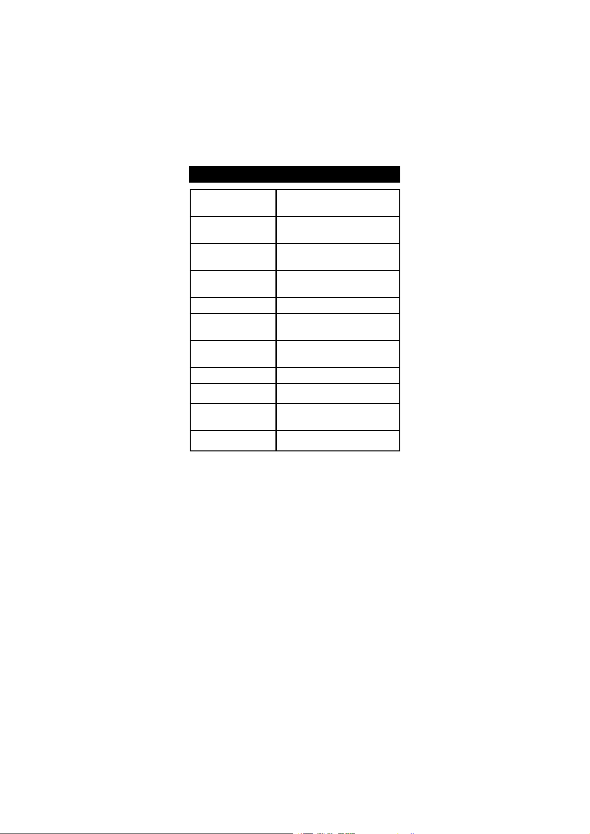
PROBE CLEANING SOLUTIONS
HI 7061M General Cleaning Solution, 230 mL bottle
HI 7061L General Cleaning Solution, 460 mL bottle
HI 8061M General Cleaning Solution, 230 mL FDA approved bottle
HI 8061L General Cleaning Solution, 460 mL FDA approved bottle
OTHER ACCESSORIES
HI 76310 Platinum 4-ring Conductivity/TDS probe with temperature sensor
and 1 m (3.3') cable.
HI 710005 12VDC voltage adapter (US plug)
HI 710006 12VDC voltage adapter (European plug)
HI 920010 9 to 9-pin connection cable
HI 92000 Windows® compatible software
RECOMMENDATIONS FOR USERS
Before using this product, make sure that it is entirely suitable for the
environment in which it is used.
Operation of this instrument in residential areas could cause unacceptable
interferences to radio and TV equipment, requiring the operator to follow all
necessary steps to correct interferences.
The metal bonds of the probe are sensitive to electrostatic discharges. Avoid
touching these metal bands at all times.
To maintain the EMC performance of this equipment, the recommended cables
must be used. Any variation introduced by the user to the supplied equipment
may degrade the instrument’s EMC performance.
To avoid electrical shock, do not use this instrument when voltages at the
measurement surface exceed 24 VAC or 60 VDC.
To avoid damage or burns, do not perform any measurements in microwave
ovens.
19
Page 20

SALES AND TECHNICAL SERVICE CONTACTS
Australia:
Tel. (03) 9769.0666 • Fax (03) 9769.0699
China:
Tel. (10) 88570068 • Fax (10) 88570060
Egypt:
Tel. & Fax (02) 2758.683
Germany:
Tel. (07851) 9129-0 • Fax (07851) 9129-99
Greece:
Tel. (210) 823.5192 • Fax (210) 884.0210
Indonesia:
Tel. (21) 4584.2941 • Fax (21) 4584.2942
Japan:
Tel. (03) 3258.9565 • Fax (03) 3258.9567
Korea:
Tel. (02) 2278.5147 • Fax (02) 2264.1729
Malaysia:
Tel. (603) 5638.9940 • Fax (603) 5638.9829
Singapore:
Tel. 6296.7118 • Fax 6291.6906
South Africa:
Tel. (011) 615.6076 • Fax (011) 615.8582
Taiwan:
Tel. 886.2.2739.3014 • Fax 886.2.2739.2983
Thailand:
Tel. 66.2619.0708 • Fax 66.2619.0061
05/05
United Kingdom:
Tel. (01525) 850.855 • Fax (01525) 853.668
USA:
Tel. (401) 765.7500 • Fax (401) 765.7575
For e-mail contacts and a complete list of Sales and
Technical offices, please see www.hannainst.com.
20
MAN2300
 Loading...