

Page 1
Instruction Manual
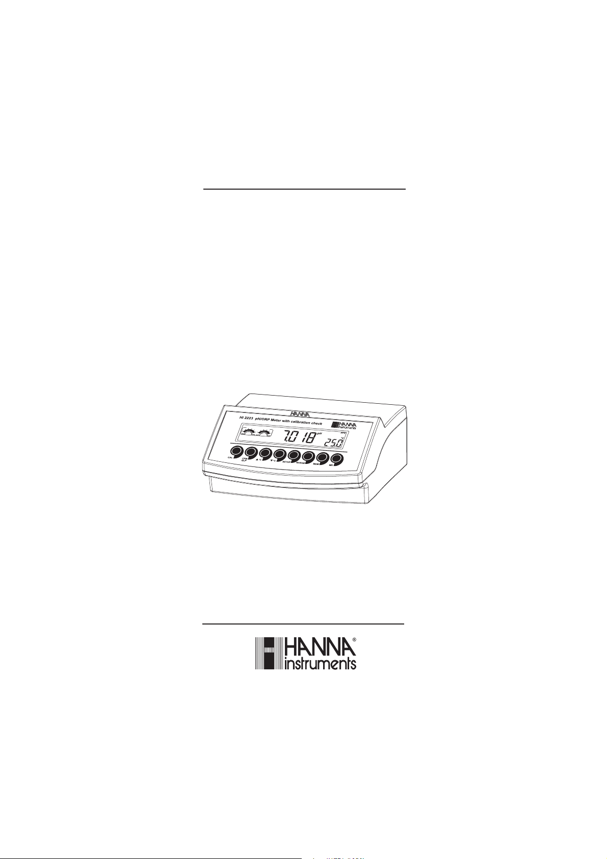
HI 2221 HI 2223
pH/mV/ºC
Bench Meters
with Calibration
Check
www.hannainst.com
1
Page 2

Dear Customer,
Thank you for choosing a Hanna Instruments product.
Please read this instruction manual carefully before using these instruments.
This manual will provide you with the necessary information for correct
use of these instruments, as well as a precise idea of their versatility.
If you need additional technical information, do not hesitate to e-mail us
at tech@hannainst.com.
WARRANTYWARRANTY
WARRANTY
WARRANTYWARRANTY
HI 2221 and HI 2223 are guaranteed for two years against defects in
workmanship and materials when used for their intended purpose and
maintained according to instructions. The electrodes and the probes are
guaranteed for a period of six months. This warranty is limited to repair
or replacement free of charge.
Damage due to accidents, misuse, tampering or lack of prescribed
maintenance are not covered.
If service is required, contact the dealer from whom you purchased the
instrument. If under warranty, report the model number, date of
purchase, serial number and the nature of the problem. If the repair is
not covered by the warranty, you will be notified of the charges incurred.
If the instrument is to be returned to Hanna Instruments, first obtain a
Returned Goods Authorization number from the Technical Service department
and then send it with shipping costs prepaid. When shipping any
instrument, make sure it is properly packaged for complete protection.
TABLE OF CONTENTSTABLE OF CONTENTS
TABLE OF CONTENTS
TABLE OF CONTENTSTABLE OF CONTENTS
WARRANTY ............................................................................................. 2
PRELIMINARY EXAMINATION ...................................................................... 3
GENERAL DESCRIPTION ............................................................................ 3
FUNCTIONAL DESCRIPTION ........................................................................ 4
HI 2221 SPECIFICATIONS ........................................................................ 5
HI 2223 SPECIFICATIONS ........................................................................ 6
OPERATIONAL GUIDE ................................................................................ 7
pH CALIBRATION ...................................................................................... 9
ENHANCED CALIBRATION MESSAGES ........................................................ 14
ELECTRODE CONDITION & ELECTRODE RESPONSE TIME ............................ 1 6
pH BUFFER TEMPERATURE DEPENDENCE .................. ............................... 17
GOOD LABORATORY PRACTICE (GLP) ........................................................ 1 8
LOGGING .............................................................................................. 21
SETUP .................................................................................................. 24
TEMPERATURE CALIBRATION (for technical personnel only) .......................... 27
mV CALIBRATION (for technical personnel only) .......................................... 29
PC INTERFACE ....................................................................................... 30
ELECTRODE CONDITIONING & MAINTENANCE ............................................. 34
TROUBLESHOOTING GUIDE ..................................................................... 37
TEMPERATURE CORRELATION FOR pH SENSITIVE GLASS ............................. 38
ACCESSORIES ........................................................................................ 39
RECOMMENDATIONS FOR USERS ............................................................. 43
2
Page 3

PRELIMINARY EXAMINATIONPRELIMINARY EXAMINATION
PRELIMINARY EXAMINATION
PRELIMINARY EXAMINATIONPRELIMINARY EXAMINATION
Remove the instrument from the packing material and examine it carefully
to make sure that no damage has occurred during shipping. If there is any
damage, notify your Dealer or the nearest Hanna Customer Service Center.
Each instrument is supplied complete with:
• HI 1131P Glass-body Combination pH Electrode with 1 m (3.3 “)
cable
• HI 7662 Temperature Probe
• HI 76404N Electrode Holder
• pH 4.01 & 7.01 Buffer Solutions (20 mL each)
• HI 7071 Electrolyte Solution
• 12 VDC Power Adapter
• Instruction Manual
Note: Save all packing material until you are sure that the instrument
functions correctly. All defective items must be returned in the
original packing with the supplied accessories.
GENERAL DESCRIPTIONGENERAL DESCRIPTION
GENERAL DESCRIPTION
GENERAL DESCRIPTIONGENERAL DESCRIPTION
HI 2221 and HI 2223 are logging microprocessor-based pH/ORP/
temperature bench meters with Calibration Check.
Calibration Check performs a set of diagnostic tests during calibration
using the history of electrode slope and offset to detect problems that can
cause loss of accuracy.
Calibration Check Features are:
• Enhanced Calibration Messages
During calibration the user is warned if one or more parameters are not suitable
to perform an accurate calibration.
• Electrode Condition on LCD Display
Determined from the electrode offset and slope.
• Electrode response time on LCD Display
Determined from electrode performance during calibration.
Other features include: up to five pH point calibration with
seven memorized buffers (1.68, 4.01, 6.86, 7.01, 9.18, 10.01 and
12.45 pH), logging up to 100 samples (for HI 2221) and 500 samples
(for HI 2223), GLP, calibration due alarm, pH reading with manual or
automatic temperature compensation and PC software interface.
3
Page 4
FUNCTIONAL DESCRIPTIONFUNCTIONAL DESCRIPTION
FUNCTIONAL DESCRIPTION
FUNCTIONAL DESCRIPTIONFUNCTIONAL DESCRIPTION
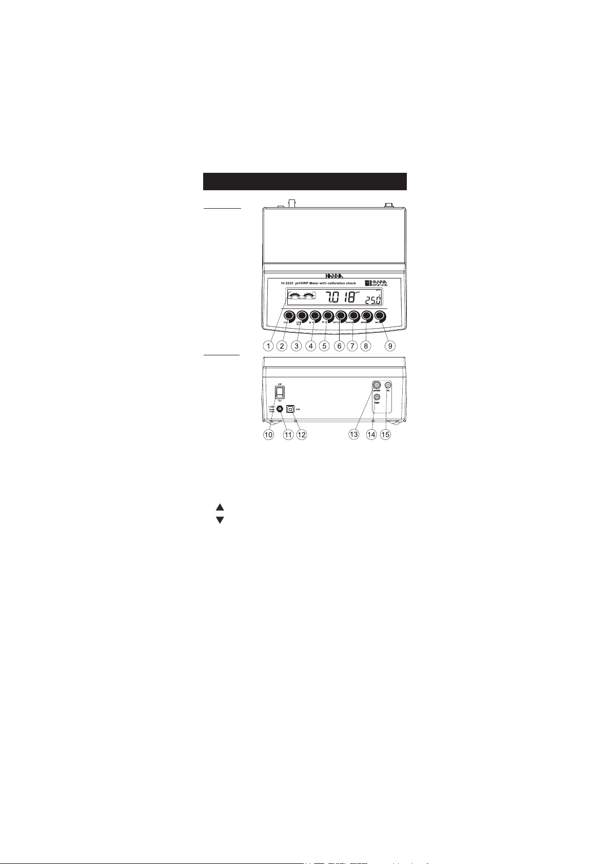
Front Panel
Rear Panel
1) Liquid Crystal Display (LCD).
2) CAL key, to enter and exit calibration mode.
3) CFM/GLP key, to confirm calibration, different values or to display
Good Laboratory Practice information.
4) ºC key, to manually increase temperature value or other parameters.
5) ºC key, to manually decrease temperature value or other parameters.
6) SETUP key, to enter/exit SETUP mode.
7) RANGE key, to select measurement range, switch to focused data in
SETUP or to toggle between buffer value and temperature during
calibration.
8) LOG/CLR key, to store a value into memory, to clear pH calibration,
or to delete log records.
9) RCL key, memory recall.
10) ON/OFF switch.
11) Power supply socket.
12) USB connector.
13) BNC electrode connector.
14)Temperature probe socket.
15) Electrode reference socket.
4
Page 5
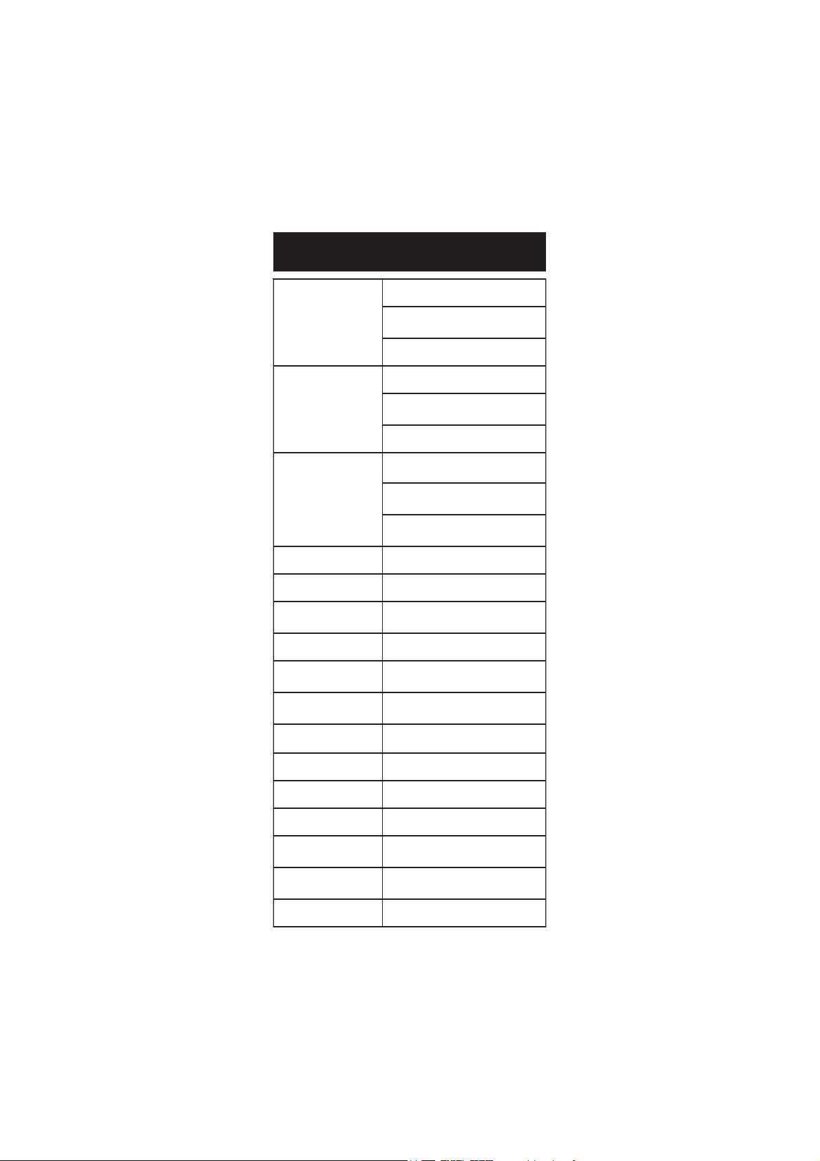
HI 2221HI 2221
HI 2221
HI 2221HI 2221
SPECIFICATIONSSPECIFICATIONS
SPECIFICATIONS
SPECIFICATIONSSPECIFICATIONS
egnaR
noituloseR
Hp00.61ot00.2–
Vm9.996±
Vm0002±
C°0.021ot0.02–
Hp10.0
)Vm9.996±(Vm1.0
)Vm0002±(Vm1
C°1.0
Hp10.0±
ycaru
ccA
F°86/C°02@
kcehCnoitarbilaCseY
ecafretnI
retupmoCBSUdetalosi-otpO
noitarbilaCHp
gniggoLstniop001
p
edortcelEH
ylppuSrewoP)dedulcni(retpadaCDV21
snoisnemiD222x532mm901x)"3.4x7.8x2.9(
thgieW
tnemnorivnE
ytnarraW2sraey
1(
noitasnepmoCerutarepmeT
eborPerutarepmeT 2667IH )dedulcni(eborp
ecnadepmItupnI01
P1311IH elballifernoitcnujelgnis,ydobssalg
)Vm9.996±(Vm2.0±
)Vm0002±(Vm1±
C°2.0±
rorreeborpgnidulcxe
elbaliavasreffub7,stniop5otpU
)54.21,10.01,81.9,10.7,68.6,10.4,86.
:morfcitamotuArolaunaM
)F°0.842ot0.4–(C°0.021ot0.02–
)dedulcni(nip+CNB,llec
leetssselniats
21
mho
;)bl9.2(gK3.1
edlohhtiwtik
)bl6.4(gK1.2r
)F°221–-23(C°05–0
gnisnednocnon%59HRxam
5
Page 6
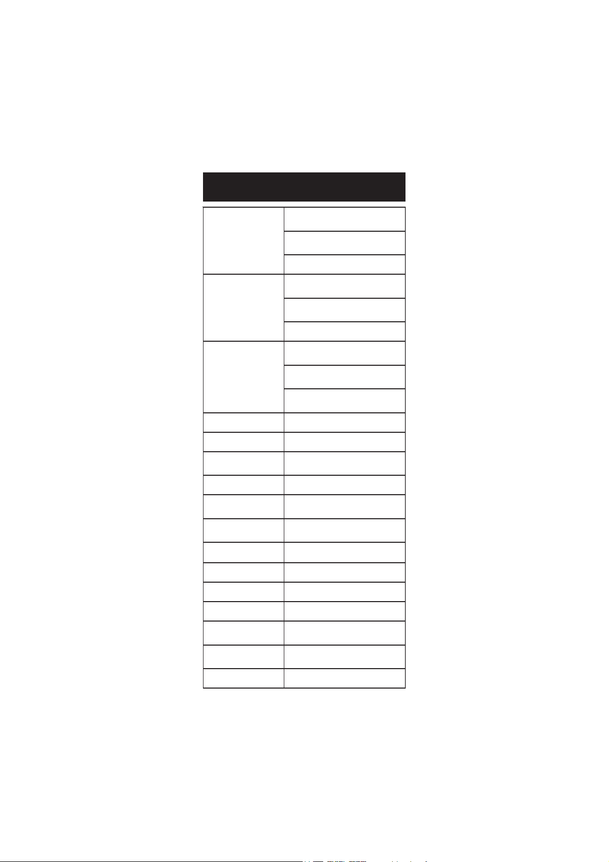
HI 2223HI 2223
HI 2223
HI 2223HI 2223
SPECIFICATIONSSPECIFICATIONS
SPECIFICATIONS
SPECIFICATIONSSPECIFICATIONS
egnaR
noituloseR
ycaruccA
F°86/C°02@
kcehCnoitarbilaCseY
afretnIretupmoCBSUdetalosI-otpO
ec
noitarbilaCHp
gniggoLstniop005
noitasnepmoCerutarepmeT
edortc
elEHp
eborPerutarepmeT 2667IH )dedulcni(e
ecnadepmItupnI01
0.4,86.1(
00.61ot00.2–Hp
9.999±Vm
0002±Vm
10.0Hp
100.0Hp
1.0Vm9.999±()Vm
1Vm0002±()Vm
°1.0C
10.0±Hp
200.0±Hp
2.0±Vm9.999±(m)V
1±Vm0002±()Vm
°2.0±C
°0.021ot0.02–(C– )F°0.842ot0.4
P1311IH noitcnujelgnis,ydobssalg
21
mho
000.61ot000.2–Hp
°0.021ot0.02–C
rorreeborpgnidulcxe
elbaliavasreffub7,stniop5otpU
)54.21,10.01,81.9,10.7,68.6,1
:morfcitamotuArolaunaM
)dedulcni(nip+CNB,llecelballifer
borpleetssselniats
ylppuSrewoPretpadaCDV21
snoisnemiD901x222x532mm)"3.4x7.8x2.9(
thgieW
tnemnorivnE
ytnarraWsraey2
ik
°05–0C °221–23(F)
6
;)bl9.2(gK3.1
)bl6.4(gK1.2redlohhtiwt
gnisnednocnon%59HRxam
Page 7
OPERATIONAL GUIDEOPERATIONAL GUIDE
OPERATIONAL GUIDE
OPERATIONAL GUIDEOPERATIONAL GUIDE
POWER CONNECTIONPOWER CONNECTION
POWER CONNECTION
POWER CONNECTIONPOWER CONNECTION
Plug the 12 VDC adapter into the power supply socket.
Notes: • These instruments use non volatile memory to retain the pH,
mV, temperature calibrations and all other settings, even
when unplugged.
• Make sure a fuse protects the mains line.
ELECTRODE AND PROBE CONNECTIONSELECTRODE AND PROBE CONNECTIONS
ELECTRODE AND PROBE CONNECTIONS
ELECTRODE AND PROBE CONNECTIONSELECTRODE AND PROBE CONNECTIONS
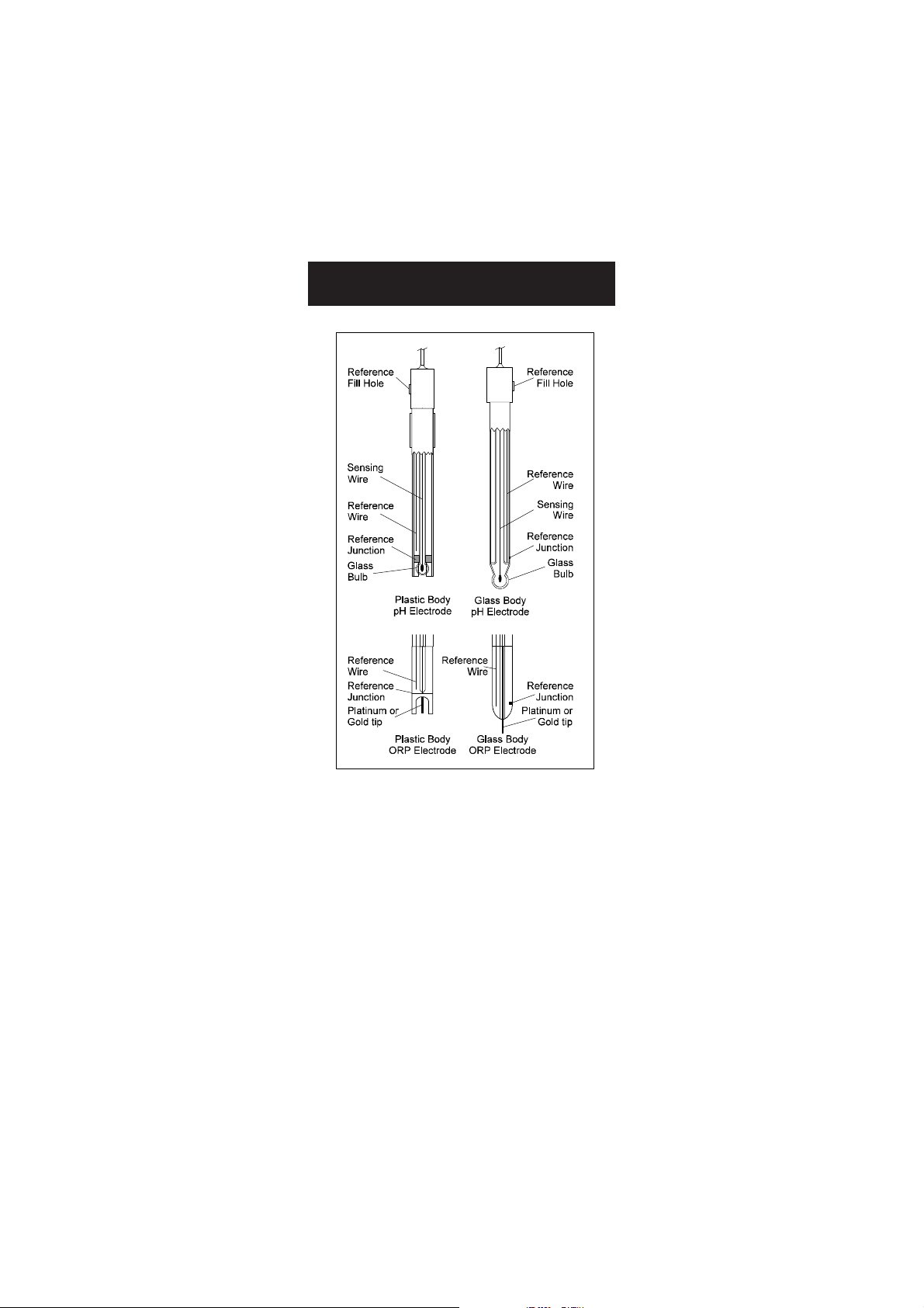
For HANNA P Type pH or ORP electrodes (with internal reference) connect
the electrode’s BNC to the socket on the back of the instrument and the
pin to the reference socket.
Note: Electrode condition and response information is displayed on the
bar graph gauges during the day the calibration is performed,
only if HANNA P type (PIN) electrodes are used.
If the electrode is not recognized as a HANNA P type electrode, the
bar graph gauges will blink (25 seconds OFF, 4 seconds ON, full
bar graph).
For temperature measurement and automatic temperature compensation
connect the temperature probe to the appropriate socket.
INSTRUMENT STINSTRUMENT ST
INSTRUMENT ST
INSTRUMENT STINSTRUMENT ST
ARTART
ART
ARTART
-UP-UP
-UP
-UP-UP
• Turn the instrument on by pressing the ON/OFF switch located on
the rear panel.
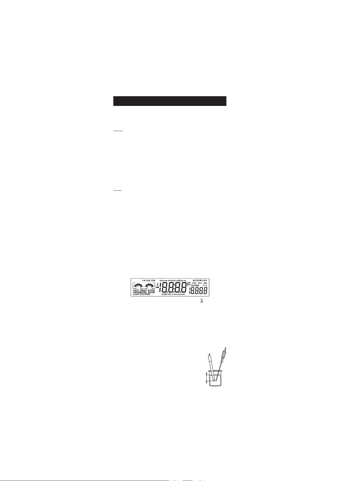
• All LCD tags are displayed and a beep is sounded while the instrument
performs a self test.
• The instrument will display “LoAD” message and “ ” blinking until
initialization is complete.
• The “Unscrew electrode refilling cap” message reminds the user
to loosen or remove the electrode refilling cap to improve the electrode’s
response time.
• The instrument automatically defaults to pH measurement mode
unless a HANNA P type ORP electrode is detected.
pH MEASUREMENTpH MEASUREMENT
pH MEASUREMENT
pH MEASUREMENTpH MEASUREMENT
Make sure the instrument has been calibrated before
taking pH measurements.
• Submerse the tip of a properly conditioned
electrode (see page 34) and the temperature
3 cm
(1¼")
7
Page 8
probe approximately 3 cm (1¼”) into the sample to be tested and stir
gently. Allow time for the electrode to stabilize.
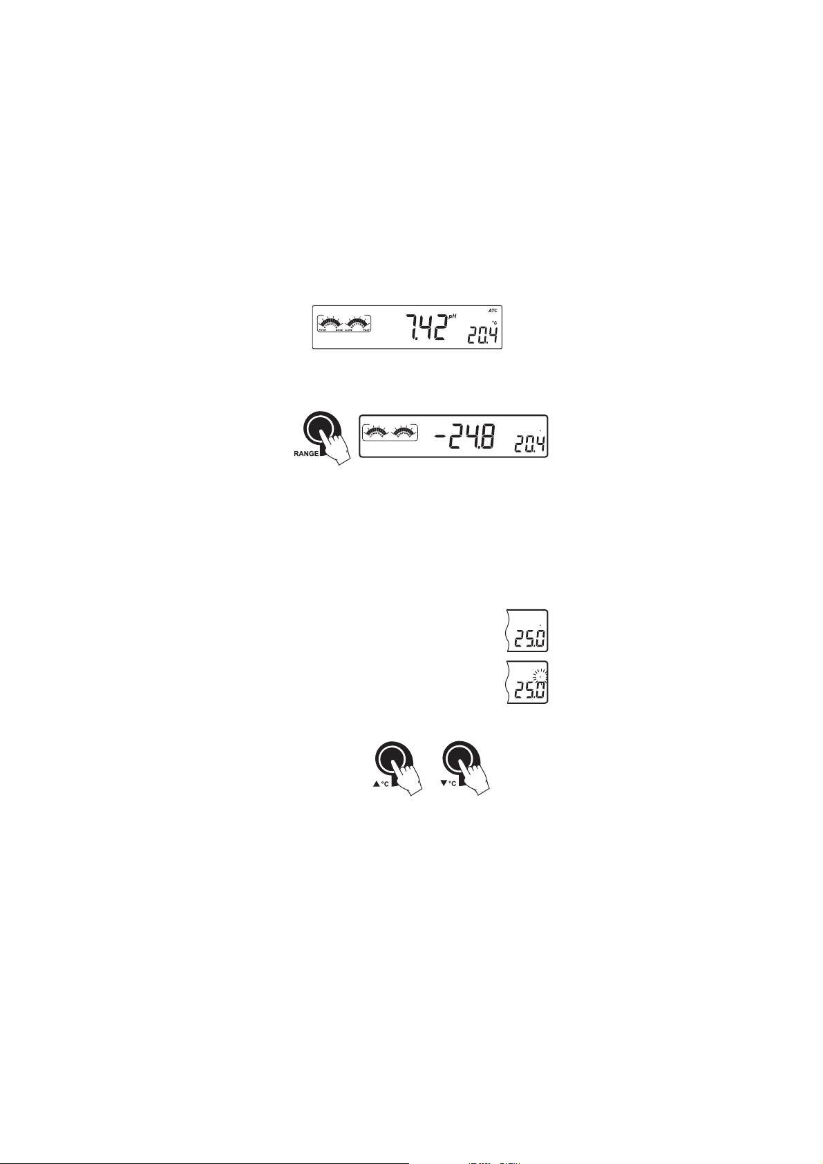
• The pH is displayed on the primary LCD and the temperature on the
secondary LCD.
• The pH reading is out of range, the closest full-scale value will be
displayed blinking on the primary LCD.
• It is also possible to view the mV reading by pressing the RANGE key.
POOR GOOD
SLOW
FAST
mV
If measurements are taken successively in different samples, it is
recommended to rinse the electrode thoroughly with deionized
water or tap water and then with some of the next sample to
prevent cross-contamination.
The pH reading is affected by temperature. In order to measure the pH
accurately, this temperature effect must be compensated for. To use the
Automatic Temperature Compensation feature, connect and submerse
the HI 7662 temperature probe into the sample as close to the electrode
as possible and wait for a few minutes.
ATC
If the temperature of the sample is known, manual
compensation can be performed by disconnecting the
temperature probe.
MTC
The display will show the last recorded temperature
reading with the “°C” symbol blinking.
The temperature can now be adjusted with the ARROW keys (from
-20.0 ºC to 120.0 ºC).
ORP MEASUREMENTSORP MEASUREMENTS
ORP MEASUREMENTS
ORP MEASUREMENTSORP MEASUREMENTS
An optional ORP electrode must be used to perform ORP measurements
(see Accessories).
Oxidation-Reduction Potential (REDOX) measurements provide the
quantification of the oxidizing or reducing power of the tested sample.
The surface of the ORP electrode must be clean and smooth in order to
obtain an accurate measurement.
C
C
C
8
Page 9
Pretreatment solutions are available to condition
the electrode and speed up the response time.
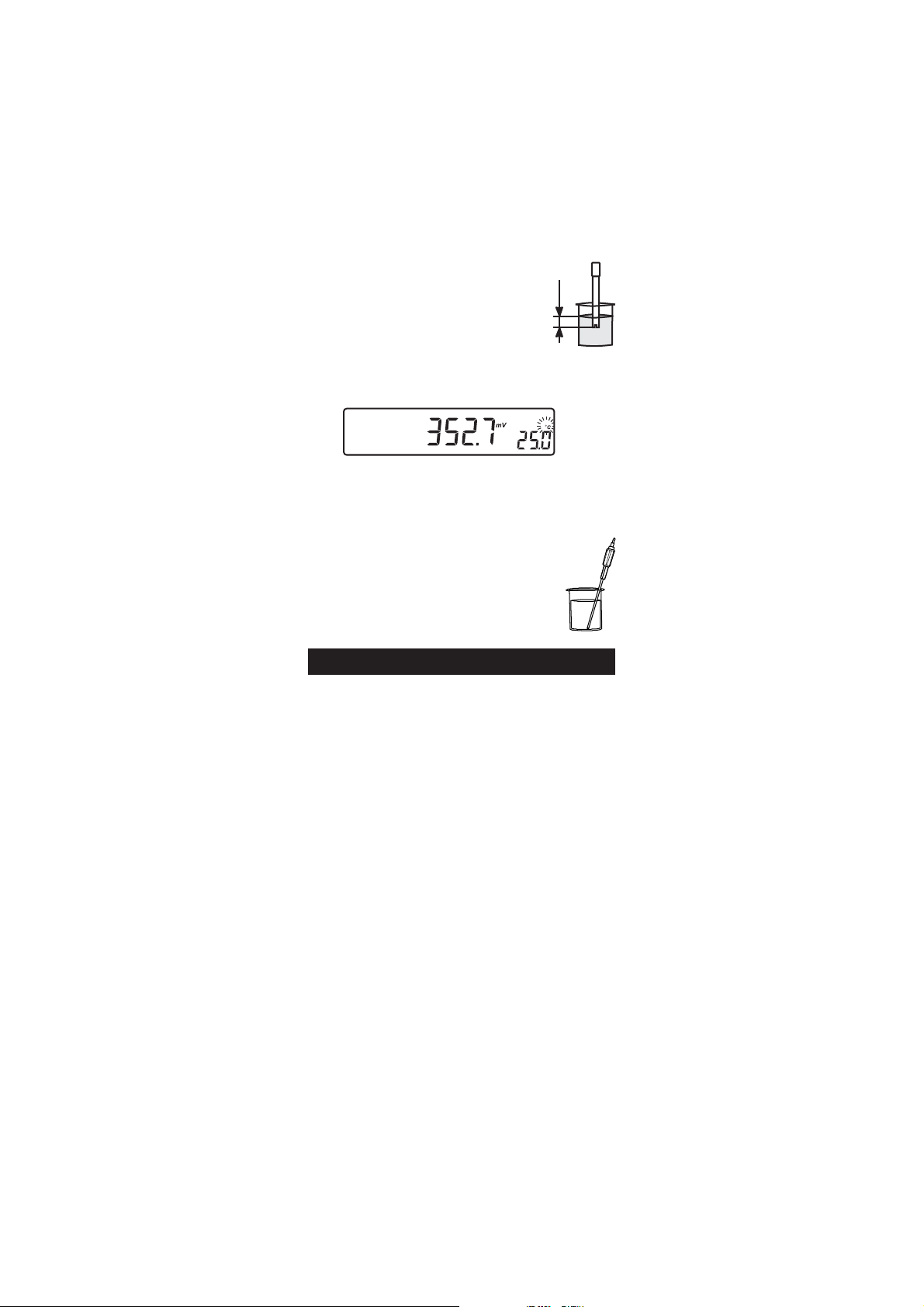
• The instrument automatically defaults to the
mV measurement mode if HANNA P type ORP
electrode is detected.
• Submerse the ORP electrode tip (3 cm/1¼”) into the sample. Allow
a few minutes for the reading to stabilize.
• The instrument displays the mV reading on the primary LCD.
• If the reading is out of range, the closest full-scale value will be
displayed blinking on the primary LCD.
TAKING TEMPERATURE MEASUREMENTSTAKING TEMPERATURE MEASUREMENTS
TAKING TEMPERATURE MEASUREMENTS
TAKING TEMPERATURE MEASUREMENTSTAKING TEMPERATURE MEASUREMENTS
Connect the HI 7662
instrument on. Dip the temperature
and allow the reading on the secondary LCD to stabilize.
Calibrate the instrument frequently, especially if high accuracy is
required. For best results and constant display of electrode condition
and electrode response on the bar graph gauges, daily calibration is
recommended.
The instrument should be recalibrated:
• Whenever the pH electrode is replaced.
• At least once a day.
• After testing aggressive chemicals.
• If high accuracy is required.
• If “CAL DUE” message is displayed during measurement.
Every time you calibrate the instrument use fresh buffers and perform an
electrode cleaning procedure (see page 36).
temperature probe and turn the
probe
into the sample
pp
H CALIBRATIONH CALIBRATION
p
H CALIBRATION
pp
H CALIBRATIONH CALIBRATION
3 cm
(1¼")
PREPARATIONPREPARATION
PREPARATION
PREPARATIONPREPARATION
Pour small quantities of the buffer solutions into clean beakers. If possible,
use plastic or glass beakers to minimize any EMC interferences.
For accurate calibration and to minimize cross-contamination, use two
beakers for each buffer solution. One for rinsing the electrode and one for
calibration.
9
Page 10
PROCEDUREPROCEDURE
PROCEDURE
PROCEDUREPROCEDURE
Calibration can be performed at up to five points. For accurate
measurements a three point calibration is recommended. Calibration
can be performed using the seven memorized buffers:
• pH 1.68, 4.01, 6.86, 7.01, 9.18, 10.01 and 12.45.
FIVE-POINT CALIBRATIONFIVE-POINT CALIBRATION
FIVE-POINT CALIBRATION
FIVE-POINT CALIBRATIONFIVE-POINT CALIBRATION
For most applications it is recommended that pH 7.01 or 6.86 buffers be
used as the first calibration point and pH 4.01 (for acidic samples) or pH
9.18/10.01 (for alkaline samples) as the second calibration point.
Note: The pH 12.45 buffer is not for general measurement; use only if
the sample is very alkaline to avoid sodium error.
• Submerse the pH electrode and the temperature probe approximately
3 cm (1¼”) into a buffer solution and stir gently. The temperature
probe should be close to the pH electrode.
• Press the CAL key. “CAL” and “pH” tags will be on, and the
“CLEAR CAL if new electrode” tag will blink.
CAL
CLEAR CAL if new electrode
pH
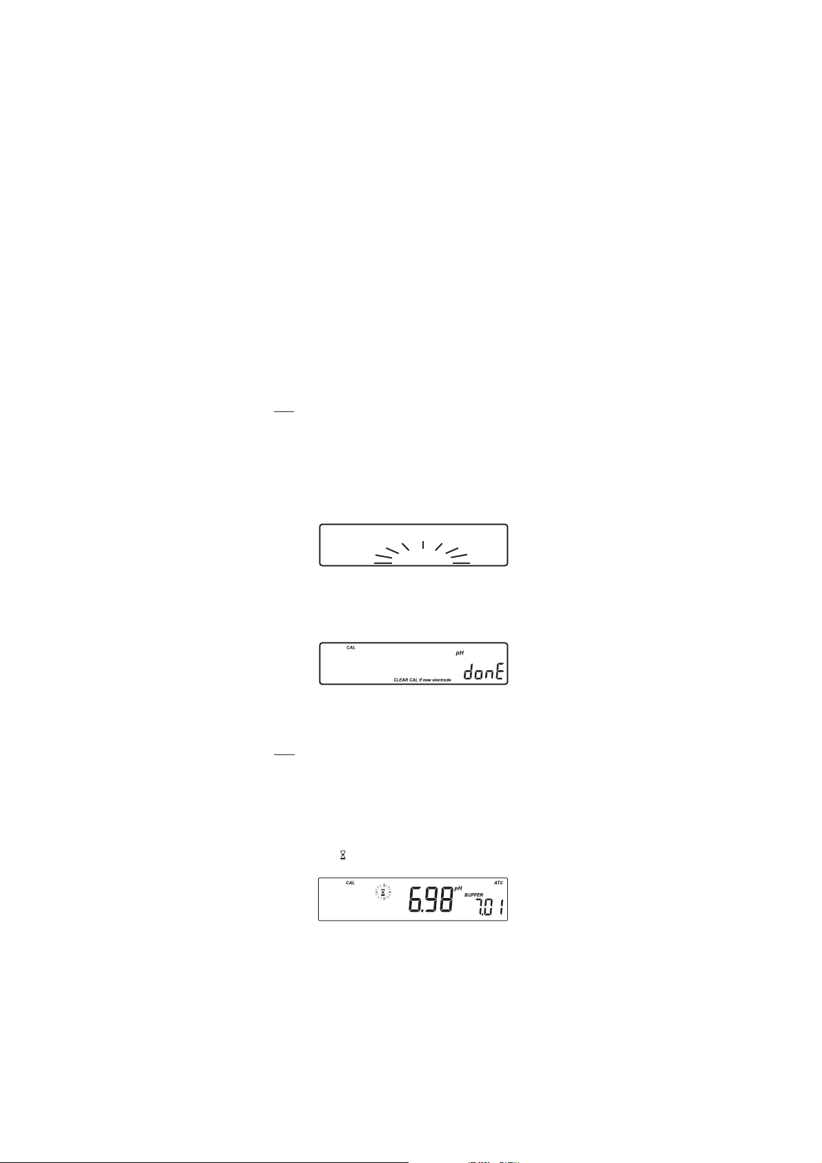
• Press the CLR key if you are using a new electrode or want to clear
the calibration history. The instrument will display the “donE” message
for a few seconds.
• Press the CAL key, or wait a few seconds to continue.
It is very important to clear the calibration history when a new electrode
is used because all error and warning messages that appear during
calibration depend on the calibration history.
Note: • The “CLEAR CAL if new electrode” will only appear if the
instrument has been previously calibrated.
• The “CAL”, “pH” and “BUFFER” tags will appear and the
“7.01” buffer will be displayed on the secondary LCD.
• If necessary, press the ARROW keys to select a different buffer
value.
• The “ ” tag will blink until the reading has stabilized.
10
Page 11
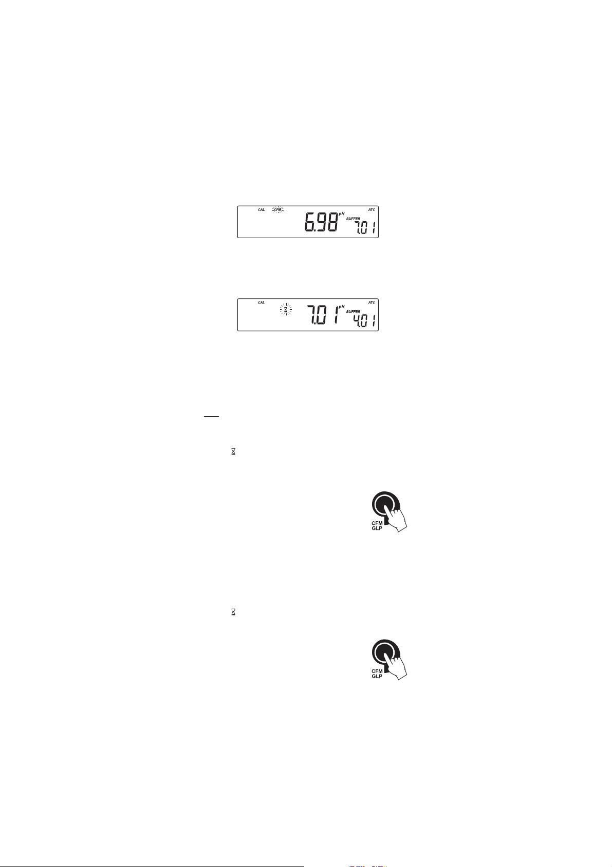
• When the reading is stable and close to the selected buffer, the
“CFM” tag will blink and if enabled, an audible signal will sound.
• Press the CFM key to confirm the calibration. The calibrated value
will be displayed on the primary LCD and the second expected buffer
value on the secondary LCD.
• After the first calibration point is confirmed, submerse the pH electrode
and the temperature probe approximately 3 cm (1¼”) into the
second buffer solution and stir gently. The temperature probe should
be close to the pH electrode.
• If necessary, press the ARROW keys to select a different buffer value.
Note: The instrument will automatically skip the buffer used for the first
point. It also skips 6.86 if 7.01 was used, and vice versa. Likewise,
it will skip 9.18 if 10.01 has been used, and vice versa.
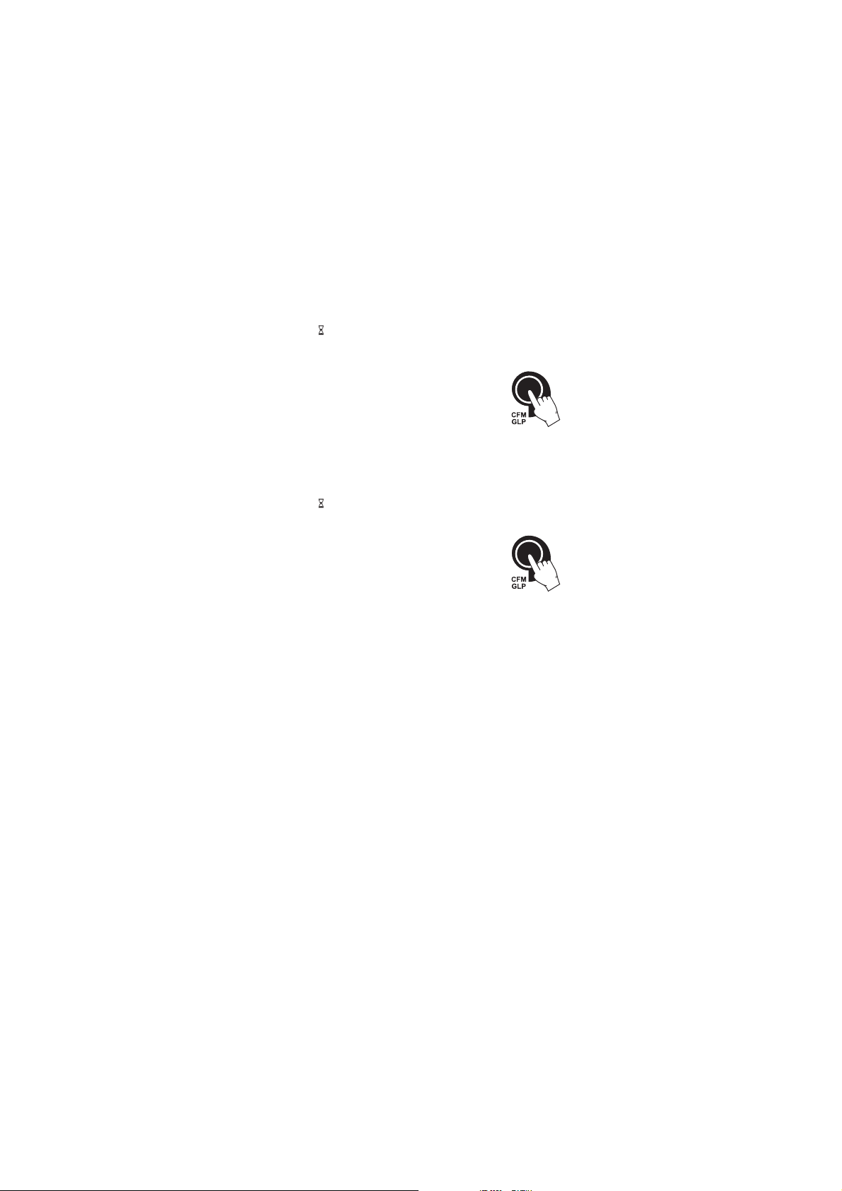
• The “ ” tag will blink on the LCD until the reading is stable.
• When the reading is stable and close to the selected buffer the “CFM”
tag will blink.
• Press CFM to confirm calibration.
• The calibrated value is then displayed on the
primary LCD and and the third expected buffer
value on the secondary LCD.
• After the second calibration point is confirmed, submerse the pH
electrode and the temperature probe approximately 3 cm (1¼”) into
the next buffer solution and stir gently. The temperature probe
should be close to the pH electrode.
• If necessary, press the ARROW keys to select a different buffer value.
• The “ ” tag will blink on the LCD until the reading is stable.
• When the reading is stable and close to the selected buffer the “CFM”
tag will blink.
• Press CFM to confirm calibration.
11
Page 12
• After the third calibration point is confirmed, submerse the pH electrode
and the temperature probe approximately 3 cm (1¼”) into the next
buffer solution and stir gently. The temperature probe should be
close to the pH electrode.
• If necessary, press the ARROW keys to select a different buffer value.
• The “ ” tag will blink on the LCD until the reading is stable.
• When the reading is stable and close to the selected buffer the “CFM”
tag will blink.
• Press CFM to confirm calibration.
• After the fourth calibration point is confirmed,
submerse the pH electrode and the temperature
probe approximately 3 cm (1¼”) into the next
buffer solution and stir gently. The temperature probe should be
close to the pH electrode.
• If necessary, press the ARROW keys to select a different buffer value.
• The “ ” tag will blink on the LCD until the reading is stable.
• When the reading is stable and close to the selected buffer the “CFM”
tag will blink.
• Press CFM to confirm calibration.
• The instrument stores the calibration value
and returns to normal measurement mode.
FOUR, THREE OR TWO-POINT CALIBRATIONFOUR, THREE OR TWO-POINT CALIBRATION
FOUR, THREE OR TWO-POINT CALIBRATION
FOUR, THREE OR TWO-POINT CALIBRATIONFOUR, THREE OR TWO-POINT CALIBRATION
• Proceed as described in “FIVE-POINT CALIBRATION” section.
• Press CAL after the fourth, third or second calibration point was
confirmed. The instrument will memorize the calibration data and
return to measurement mode.
ONE-POINT CALIBRATIONONE-POINT CALIBRATION
ONE-POINT CALIBRATION
ONE-POINT CALIBRATIONONE-POINT CALIBRATION
Two SETUP selectable options are available: “Pnt” and “OFFS”.
If the “Pnt” option is selected, the new calibration point overrides an
existing one. The adjacent slopes will be reevaluated.
If the “OFFS” option is selected, an electrode offset correction is performed.
The adjacent slopes will remain unchanged.
• Proceed as described in “FOUR, THREE or TWO-POINT CALIBRATION”
section.
• Press CAL after the first calibration point was confirmed. The
instrument will memorize the one-point calibration data and return
to measurement mode.
12
Page 13
Notes: • To clear calibration parameters for all uncalibrated buffers
starting with current buffer, press CLR. The calibration
will continue from the current point. If this procedure is
performed while calibrating in the first calibration point,
the instrument returns to measurement mode.
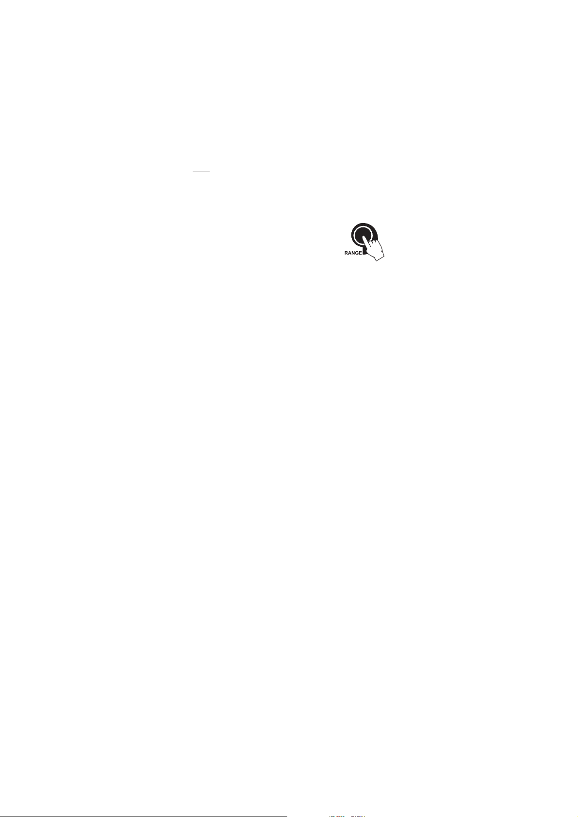
• Press RANGE to toggle between pH
buffer, calibration buffer number and
temperature reading.
13
Page 14
ENHANCED CALIBRATION MESSAGESENHANCED CALIBRATION MESSAGES
ENHANCED CALIBRATION MESSAGES
ENHANCED CALIBRATION MESSAGESENHANCED CALIBRATION MESSAGES
The stored calibration history to used issue error and warning messages
during calibration to help ensure the highest accuracy.
As electrode aging is normally a slow process, substantial changes
from previous calibrations are likely due to a temporary problem
with the electrode or buffers.
ERROR MESSAGES
Error messages appear if one or all of the calibration parameters are out
of accepted windows. Calibration can not continue when these errors are
displayed.
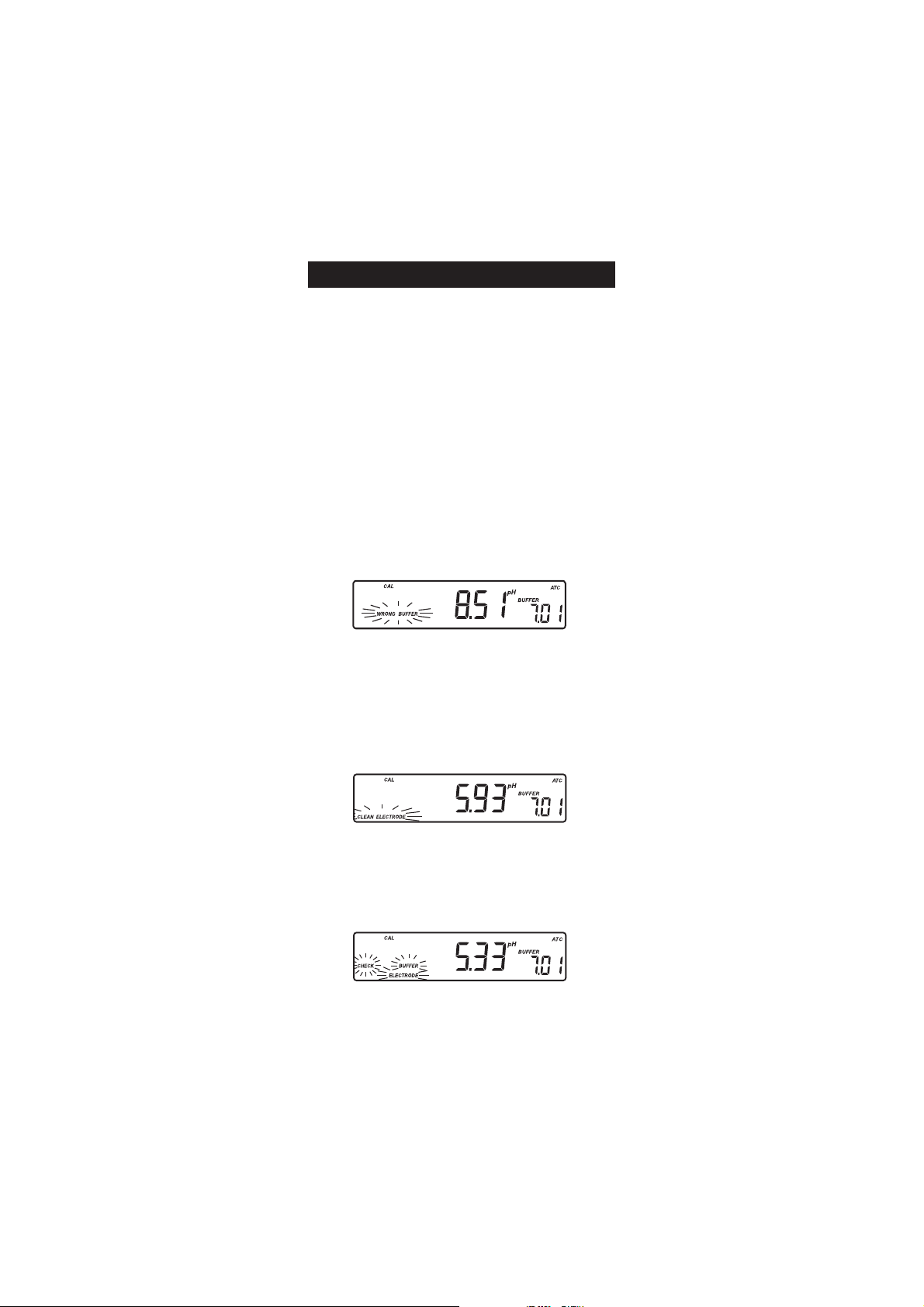
WRONG BUFFERWRONG BUFFER
WRONG BUFFER
WRONG BUFFERWRONG BUFFER
This message appears when the difference between the pH reading and
the value of the selected buffer is too big. If this error message is
displayed, check if you have selected the proper calibration buffer.
CLEAN ELECTRODECLEAN ELECTRODE
CLEAN ELECTRODE
CLEAN ELECTRODECLEAN ELECTRODE
This error message indicates a bad electrode condition (offset out of
accepted window, or slope under the accepted lower limit).
Clean the electrode according to the Cleaning Procedure on page 36 to
improve its condition and repeat the calibration. This ensures the
removal of film, dirt or deposits on the glass bulb and reference junction.
CHECK ELECTRODE CHECK ELECTRODE
CHECK ELECTRODE alternating with
CHECK ELECTRODE CHECK ELECTRODE
This error message appears when electrode slope exceeds the highest
accepted slope limit. You should check your electrode and use fresh
buffer.
ELECTRODEELECTRODE
ELECTRODE
ELECTRODEELECTRODE
This message appears if the cleaning procedure performed as a result of
the above two messages is found by the instrument to be unsuccessful.
14
CHECK BUFFER CHECK BUFFER
CHECK BUFFER
CHECK BUFFER CHECK BUFFER
Page 15

Replace the electrode.
BUFFER TEMPERATUREBUFFER TEMPERATURE
BUFFER TEMPERATURE
BUFFER TEMPERATUREBUFFER TEMPERATURE
This message appears if the temperature of the buffer is outside the
defined buffer temperature range.
WARNING MESSAGES
During calibration, the Calibration Check feature analyzes the electrode
calibration history and warns the user when problems have been
detected. It is possible to over ride the warning messages and confirm the
calibration but it is not recommended.
CLEAN ELECTRODECLEAN ELECTRODE
CLEAN ELECTRODE
CLEAN ELECTRODECLEAN ELECTRODE
This warning appears during Calibration Check for the second calibration
buffer when the instrument has detected a small variation of offset or
both offset and slope parameters. This variation may result from dirt on
the electrode. Refer to the electrode cleaning procedure. This ensures the
removal of film, dirt or deposits on the glass bulb and reference junction.
CLEAN ELECTRODE CLEAN ELECTRODE
CLEAN ELECTRODE alternating with
CLEAN ELECTRODE CLEAN ELECTRODE
This warning appears during Calibration Check in the first calibration
buffer as a result of unacceptable offset variation or in the second
calibration buffer as a result of unacceptable slope variation. This
variation may result from dirt on the electrode or contaminated buffer.
Refer to the electrode cleaning procedure or use fresh buffer.
CONTAMINATED BUFFERCONTAMINATED BUFFER
CONTAMINATED BUFFER
CONTAMINATED BUFFERCONTAMINATED BUFFER
This warning message appears in order to alert that the buffer could be
contaminated. Refresh your buffer and continue the calibration procedure.
15
CHECK BUFFER CHECK BUFFER
CHECK BUFFER
CHECK BUFFER CHECK BUFFER
Page 16
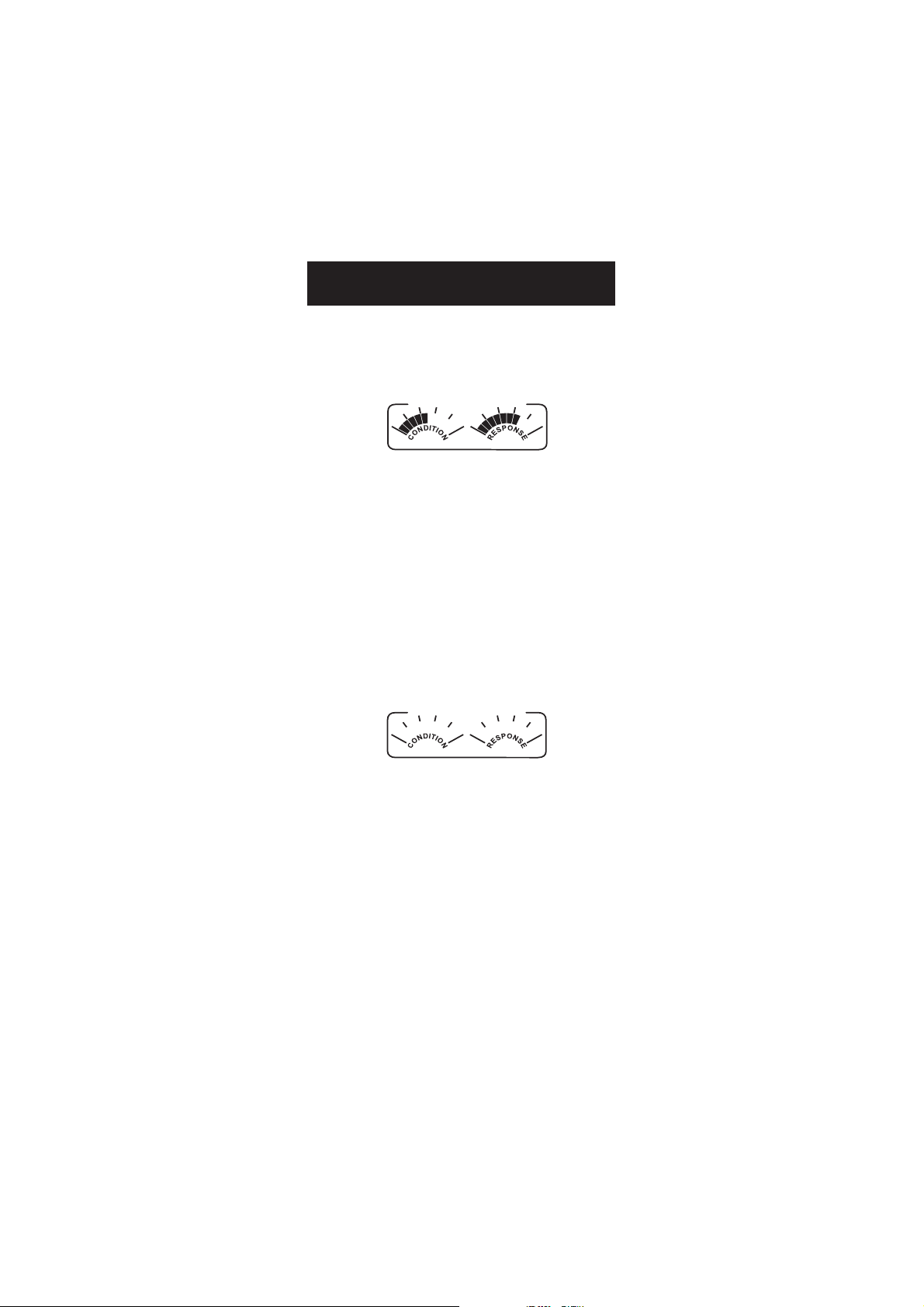
ELECTRODE CONDITION &ELECTRODE CONDITION &
ELECTRODE CONDITION &
ELECTRODE CONDITION &ELECTRODE CONDITION &
ELECTRODE RESPONSE TIMEELECTRODE RESPONSE TIME
ELECTRODE RESPONSE TIME
ELECTRODE RESPONSE TIMEELECTRODE RESPONSE TIME
When using an appropriate HANNA P Type BNC electrode with pin,
HI 2221 and HI 2223 will assess electrode condition and response time
during each calibration, the calibration status is displayed for the rest
of the day.
POOR GOOD
SLOW
FAST
The response gauge is a function of the stabilization time between the
first and second calibration buffers. These gauges reflect electrode
performance and should be expected to slowly decrease over the life of
the electrode.
The condition gauge show the electrode’s condition at the time of
calibration.
For a continuous display of electrode condition and response, daily
calibration is necessary. This information can also be viewed in the GLP
data.
If the instrument is not calibrated, the calibration history was deleted,
or it has been calibrated only at one point, the electrode condition and
the electrode response gauges will be empty.
POOR GOOD
SLOW
FAST
When the instrument cannot evaluate the electrode response, the
response gauge will be empty (pH 1.68 or pH 12.45 were used).
If the electrode is in a very poor condition the first condition segment will
blink.
If electrode response is very slow the first response segment will blink.
16
Page 17
pp
H BUFFER TEMPERATUREH BUFFER TEMPERATURE
p
H BUFFER TEMPERATURE
pp
H BUFFER TEMPERATUREH BUFFER TEMPERATURE
DEPENDENCEDEPENDENCE
DEPENDENCE
DEPENDENCEDEPENDENCE
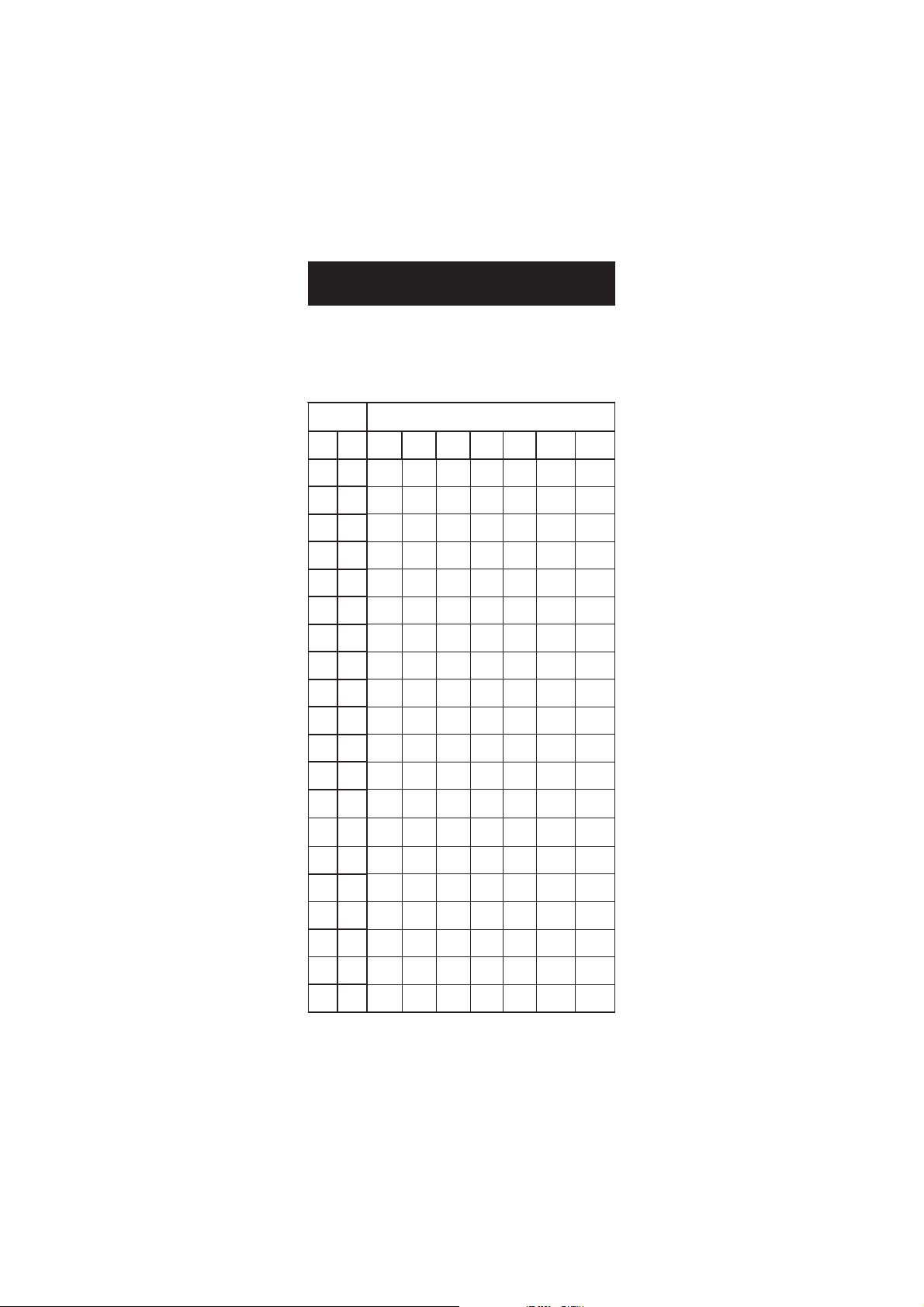
The temperature has an effect on pH. The calibration buffer solutions are
affected by temperature changes to a lesser degree than normal solutions.
During calibration the instrument will automatically calibrate to the
pH value corresponding to the measured or set temperature.
PMETSREFFUBHp
CºFº86.110.468.610.781.910.0154.21
023 76.110.489.631.764.923.0183.31
514 76.100.459.601.793.942.0181.31
0105 76.100.429
5195 76.100.409.650.772.921.0108.21
0286 86.100.488.630.722.960.0126.21
5277 86.110.468.610.781.910.0154.21
0368 8
5359 96.130.448.699.611.929.931.21
04401 96.140.448.689.670.988.989.11
54311 07.150.438.689.640.958.938.1
05221 17.160.438.689.610.928.907.11
55131 27.180.448.689.699.897.975.11
06041 27.190.448.689.679.877.944.11
56941 37.111.448.699.659.867.923.11
07851 47.121.458.699.639.857.912.11
57761 67.141.468.600.719.847.901.11
08671 77.161.478.610.798.847.900.11
58581 87.171.478
09491 97.191.488.630.758.857.928.01
6.120.458.600.741.969.992.21
.670.733.981.0199.21
.620.778.847.919.01
1
59302 18.102.498.640.738.867.937.01
During calibration the instrument will display the pH buffer value at 25 ºC.
17
Page 18
GOOD LABORATORY PRACTICE (GLP)GOOD LABORATORY PRACTICE (GLP)
GOOD LABORATORY PRACTICE (GLP)
GOOD LABORATORY PRACTICE (GLP)GOOD LABORATORY PRACTICE (GLP)
GLP is a set of functions that allows the storage and retrieval of data
regarding the maintenance and status of the electrode.
All data regarding the last calibration is stored for the user to review
when necessary.
EXPIRED CALIBRATIONEXPIRED CALIBRATION
EXPIRED CALIBRATION
EXPIRED CALIBRATIONEXPIRED CALIBRATION
These instruments allow the user to set the number of days before the
next required calibration. This value can be set from 1 to 7 days. The
default setting is OFF (disabled).
The “CAL DUE” tags will blink to warn the user that the instrument
should be recalibrated.
For example, if a 4 days time out has been selected, the instrument will
issue the alarm exactly 4 days after the last calibration.
If the expiration value is changed (e.g. to 5 days), then the alarm will
be immediately recalculated and appear 5 days after the last calibration.
Notes: • If the instrument was not calibrated, or if the calibration
history was deleted, the “CAL DUE” message will be
displayed even if this feature is disabled in the SETUP menu.
• If the instrument was calibrated using an electrode with pin
and the electrode is changed with an electrode without pin
or vice-versa “CAL DUE” will blink. This feature helps
ensure use of a calibrated instrument.
pp
H CALIBRATION DATAH CALIBRATION DATA
p
H CALIBRATION DATA
pp
H CALIBRATION DATAH CALIBRATION DATA
Calibration data is stored automatically after a successful calibration.
To view the pH calibration data, press the GLP key when the instrument
is in pH measuring mode.
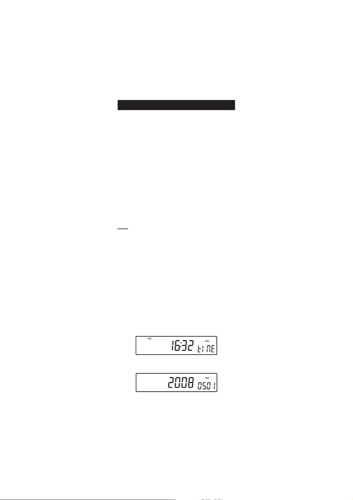
The instrument will display the time of the last calibration.
Use the ARROW keys to scroll through the calibration data:
••
• The time (hh:mm).
••
••
• The date (yyyy / mm.dd).
••
18
Page 19
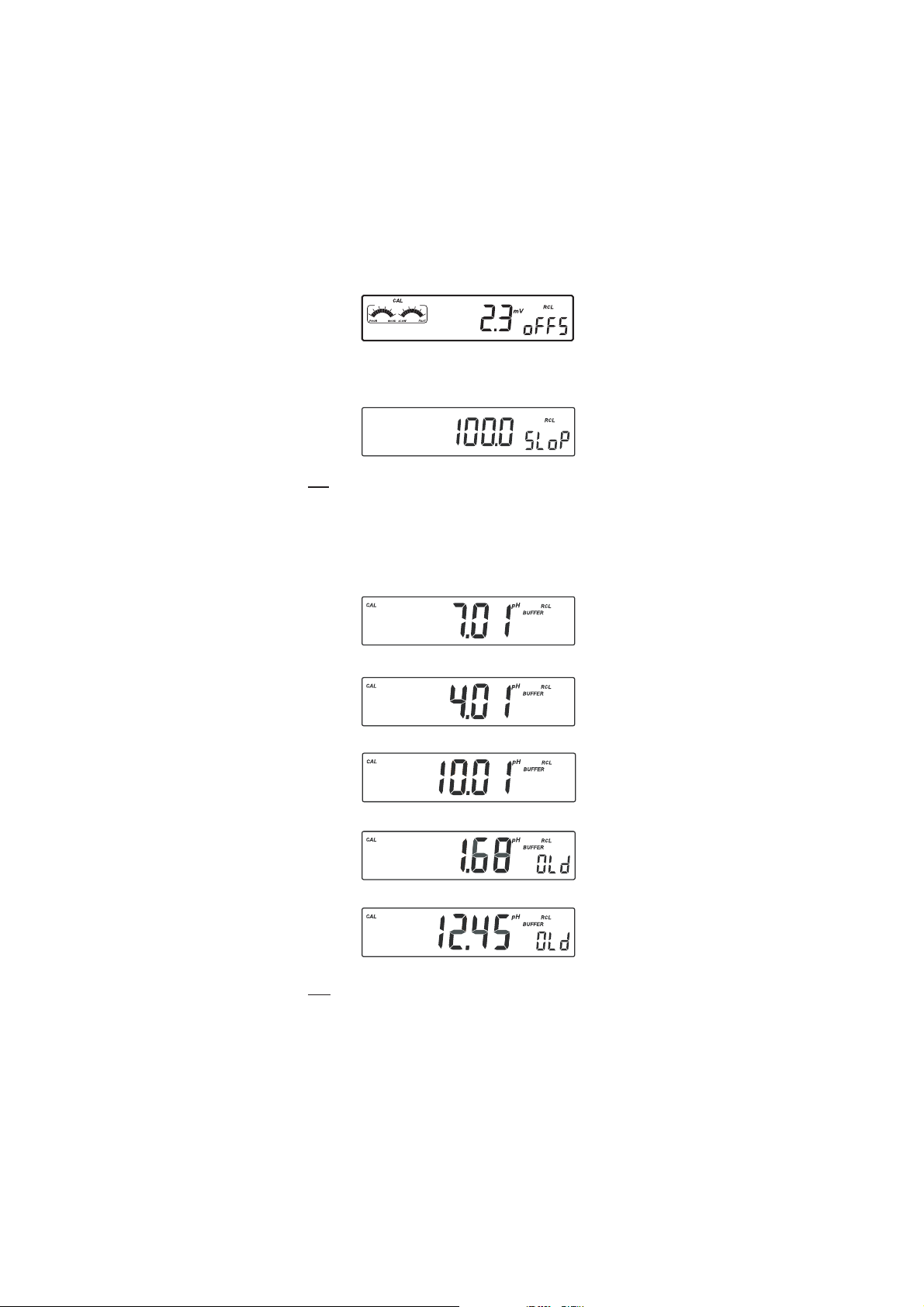
••
• The pH calibration offset.
••
••
• The pH calibration slope in mV/pH normalized to 25 °C (the
••
percentage is referred to the ideal value of 59.16 mV/pH).
Note: If you calibrate using electrodes with pin the electrode condition
and response gauges appear while the offset and slope are
displayed.
• The pH calibration buffers in calibrating order and with the selected
resolutions used during calibration.
The first pH calibration buffer:
The second pH calibration buffer:
The third pH calibration buffer:
The fourth pH calibration buffer:
The fifth pH calibration buffer:
Note: The “OLd” message displayed beside the pH value means that
this buffer was not used during last calibration. Press and hold
down SETUP if you want to see calibration date (or time, if old
calibration was performed on the same day as the current calibration).
19
Page 20
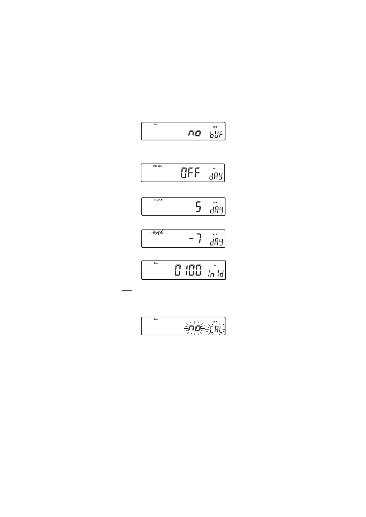
• If “no bUF” message appears on the LCD, the instrument informs
you that the calibration was performed with less than five buffers.
• Calibration Expiration status:
- if disabled.
- or the number of days until the calibration alarm will be displayed,
- or if expired (7 days ago).
• The instrument ID.
Notes: • Press GLP to return to measurement mode.
• If calibration has not been performed, the instruments
display “no CAL” message blinking.
20
Page 21
LOGGINGLOGGING
LOGGING
LOGGINGLOGGING
Up to 100 (HI 2221) or 500 (HI 2223) logged samples can be stored in
memory.
LOGGING THE CURRENT DATALOGGING THE CURRENT DATA
LOGGING THE CURRENT DATA
LOGGING THE CURRENT DATALOGGING THE CURRENT DATA
To store the current reading into memory press the LOG key while in
measuring mode.
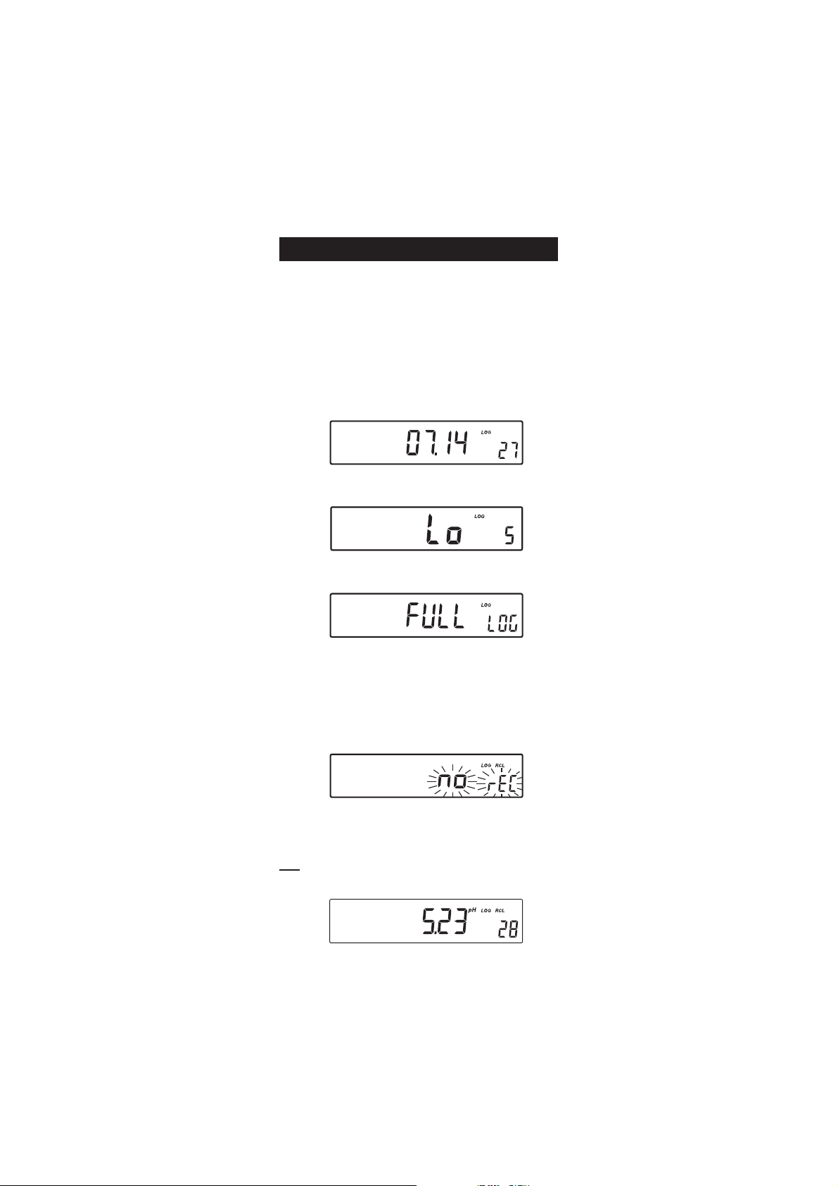
The instrument will display the current date (mm.dd) on the primary
LCD, the record number on the secondary LCD and the “LOG” tag will
blink for a few seconds (see example below: record No. 27 dated July 14):
If there are less than 5 memory locations remaining, the record number
and the “Lo” message will be displayed to alert the user.
If the log space is full, the “FULL LOG” message will be displayed and
no more data will be saved.
Along with the current measurement, the date, time, mV value,
temperature and calibration data is stored. If a HANNA P Type ORP
electrode is used pH information is not stored.
VIEW LOGGED DATAVIEW LOGGED DATA
VIEW LOGGED DATA
VIEW LOGGED DATAVIEW LOGGED DATA
Press RCL
while in measurement mode to retrieve the stored information.
If no data was logged, the instrument displays:
The instrument will display the logged measurement value on the
primary LCD and the record number on the secondary LCD, along with
the “LOG” and “RCL” tags.
Note: The “LOG” and “RCL” tags remain on LCD while in memory recall
mode.
21
Page 22
Press the RCL key to return to measurement mode.
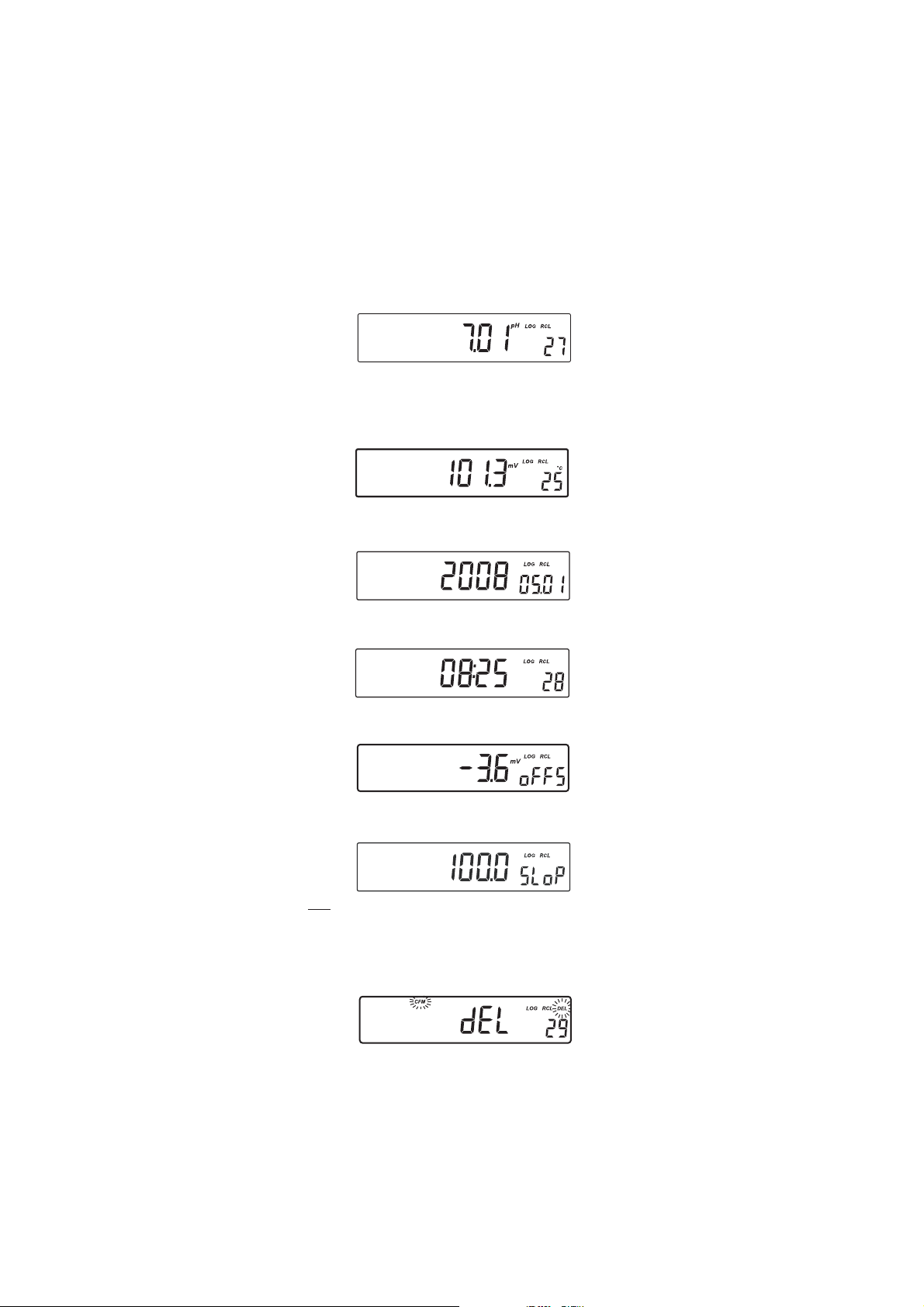
Use the ARROW keys to scroll through the stored records:
Press the RANGE key to view additional data:
• The mV value on the primary LCD and the temperature on the
secondary LCD.
• The year on the primary LCD and the month and day on the
secondary LCD.
• The hour and minutes on the primary LCD and the record
number on the secondary LCD.
• The calibration offset on the primary LCD and the “oFFS” message
on the secondary LCD.
• The calibration slope on the primary LCD and the “SLoP” message
on the secondary LCD.
Note: On the screens where record number is not displayed press the
SETUP key to display the record number.
• To delete records press CLR key. The “dEL” message will be displayed
on the primary LCD and the selected record on the secondary LCD.
The “CFM” and the ”DEL” tags will blink:
22
Page 23
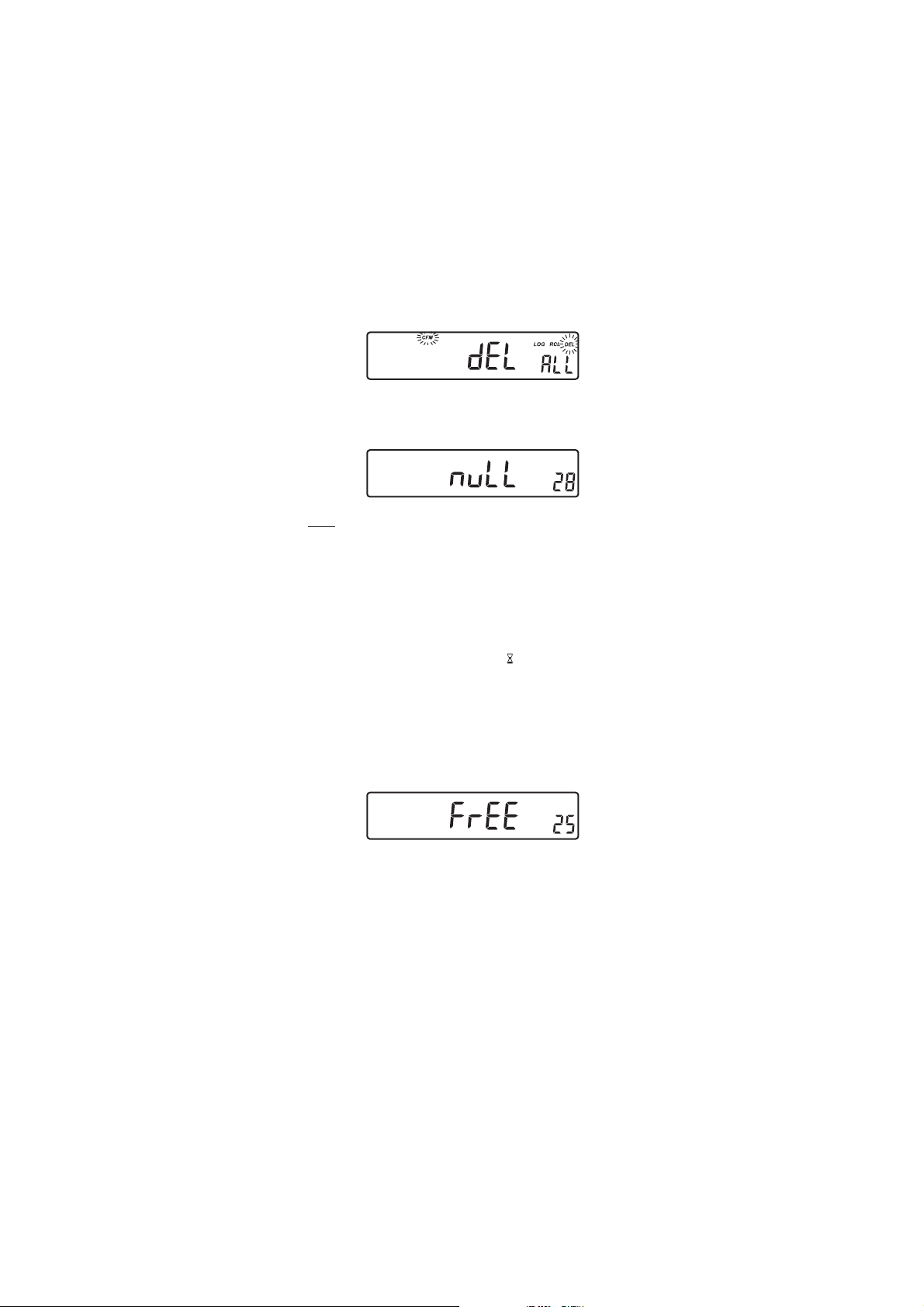
Press the ARROW keys to change the selected record.
To delete all records press the SETUP key, “ALL” tag will appear on
the secondary LCD.
Press the CFM key to confirm the deleting of the selected record, or all
records. Instrument will display on the primary LCD the “nuLL” message.
LOG
RCL
Notes: • The RANGE key has no effect if “nuLL” record message is
displayed on the first LCD line.
• You can skip this message by selecting an undeleted record
using the ARROW keys.
• The instrument optimizes the usage of the memory when it
returns to measurement mode after a deleting operation is
performed. This will change the record numbers of logged
data. During this operation the “ ” tag will blink.
• If all the records are deleted the instrument returns to the
measuring mode.
• After the LOG key is pressed or “dEL” is confirmed the
instrument will display the amount of free log space for
about one second (example: 25 records free).
23
LOG
Page 24

SETUPSETUP
SETUP
SETUPSETUP
Setup mode allows viewing and modification of the following parameters:
• Calibration Expiration Alarm
• One-point Calibration Behavior
• pH Resolution (HI 2223 only)
• Current Time (hour & minute)
• Current Date (year, month & day)
• Beep Status
• Instrument ID
• Temperature Unit
To enter the Setup mode press the SETUP key while the instrument is in
measuring mode. Press SETUP key to exit SETUP mode.
Select a parameter with the ARROW keys.
Press the CAL key to change a parameter value. The selected parameter
will start blinking.
Press the RANGE key to toggle between the displayed parameters.
Press the ARROW
Press the CFM key to save the modified value or the CAL key to escape
without saving.
Press the ARROW keys to select the next/previous parameter.
CALIBRATION EXPIRATION ALARMCALIBRATION EXPIRATION ALARM
CALIBRATION EXPIRATION ALARM
CALIBRATION EXPIRATION ALARMCALIBRATION EXPIRATION ALARM
Press the CAL key when the calibration expiration is displayed. Calibration
time out (“OFF” or “1” to “7” days) will begin blinking.
keys to increase or decrease the displayed value.
Press the ARROW
Press the CFM key to save the modified calibration expiration value or
press the CAL key to cancel without saving the calibration expiration.
ONE-POINT CALIBRATION BEHAVIORONE-POINT CALIBRATION BEHAVIOR
ONE-POINT CALIBRATION BEHAVIOR
ONE-POINT CALIBRATION BEHAVIORONE-POINT CALIBRATION BEHAVIOR
Press CAL when “1 Pnt” message is displayed on the secondary LCD. One of
the two options (“Pnt” or “OFFS”) will start blinking (see pH
CALIBRATION, ONE-POINT CALIBRATION for details, page 12).
Press the ARROW keys to toggle between “Pnt” and “OFFS” options.
keys to change the calibration expiration value.
24
Page 25
Press CFM to save the behavior for one-point calibration.
Press CAL to escape without saving.
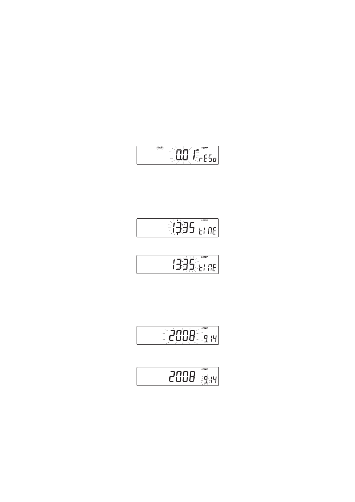
pH RESOLUTION (HI 2223 only)pH RESOLUTION (HI 2223 only)
pH RESOLUTION (HI 2223 only)
pH RESOLUTION (HI 2223 only)pH RESOLUTION (HI 2223 only)
Press CAL when “rESo” message is displayed on the secondary LCD. The
set resolution (“0.01” or ”0.001”) will start blinking.
Press the ARROW keys to toggle between 0.01 and 0.001 options.
Press CFM to save the modified value.
Press CAL to escape without saving.
CURRENT TIMECURRENT TIME
CURRENT TIME
CURRENT TIMECURRENT TIME
Press the CAL key when the current time is displayed. The hour will start
blinking.
Press the ARROW
Press the RANGE key. The minutes will start blinking.
Press the ARROW keys to change the displayed value.
Press the CFM key to save the modified value or press the CAL key to
escape without saving.
CURRENT DATECURRENT DATE
CURRENT DATE
CURRENT DATECURRENT DATE
Press the CAL key when the current date is displayed. The year will start
blinking.
Press the ARROW
Press the RANGE key. The month will start blinking.
Press the ARROW keys to change the month.
keys to change the hour.
keys to change the year.
25
Page 26

Press the RANGE key. The day will start blinking.
Press the ARROW keys to change the day.
Press the CFM key to save the modified value or press the CAL key to
escape without saving.
BEEP STATUSBEEP STATUS
BEEP STATUS
BEEP STATUSBEEP STATUS
Press CAL when the beep status is displayed. Beep status (“On” or
“OFF”) will start blinking.
Press the ARROW
Press CFM to save the modified beep status.
Press CAL to escape without saving.
When enable, beep sounds as a short beep every time a key is pressed or
when the calibration can be confirmed.
A long beep alert that the pressed key is not active or a wrong condition
is detected while in calibration.
II
NSTRUMENT IDNSTRUMENT ID
I
NSTRUMENT ID
II
NSTRUMENT IDNSTRUMENT ID
Press the CAL key when “InId” is displayed. The instrument ID (“0000”
to “9999”) will begin blinking.
Press the ARROW
Press the CFM key to save the modified instrument ID value or press the
CAL key to cancel without saving the instrument ID.
Note: The instrument ID is downloaded to a PC as part of a logged data
set to identify it’s origin.
TEMPERATURE UNITTEMPERATURE UNIT
TEMPERATURE UNIT
TEMPERATURE UNITTEMPERATURE UNIT
Press CAL when “tenP” is displayed. The temperature unit will start
blinking.
keys to change the beep status (On or OFF).
keys to change the instrument ID value.
Press the ARROW keys to change the option.
Press CFM to save the modified temperature unit.
Press CAL to escape without saving.
26
Page 27

TEMPERATURE CALIBRATIONTEMPERATURE CALIBRATION
TEMPERATURE CALIBRATION
TEMPERATURE CALIBRATIONTEMPERATURE CALIBRATION
((
(for technical personnel only
((
All the instruments are factory calibrated for temperature.
Hanna’s temperature probes are interchangeable and no temperature
calibration is needed when they are replaced.
If the temperature measurements are inaccurate, temperature recalibration
should be performed.
For an accurate recalibration, contact your dealer or the nearest Hanna
Customer Service Center, or follow the instructions below.
• Prepare a vessel containing ice and water and another one containing
hot water (around 50 ºC). Place insulation material around the
vessels to minimize temperature changes.
• Use a calibrated thermometer with a resolution of 0.1 ºC as a
reference thermometer.
• With the instrument off, press and hold down the CFM & SETUP
keys, then power on the instrument. The “CAL” tag will appear and
the secondary LCD will show “0.0 ºC“.
• Submerse the temperature probe in the vessel with ice and water as
near as possible to the reference thermometer. Allow a few seconds for
the probe to stabilize.
• Use the ARROW keys to set the reading on the secondary LCD to that
of ice and water, measured by the reference thermometer. When the
reading is stable and close to the selected calibration point, “READY”
tag will appear and “CFM” tag will blink.
))
)
))
• Press CFM to confirm. The secondary LCD will show “50.0 ºC“.
• Submerse the temperature probe in the second vessel as near as
possible to the reference thermometer. Allow a few seconds for the
probe to stabilize.
• Use the ARROW keys to set the reading on the secondary LCD to that
of the hot water.
27
Page 28

• When the reading is stable and close to the
selected calibration point, “READY” tag will
appear and “CFM” tag will blink.
• Press CFM to confirm. The instrument returns to
measurement mode.
Note: If the reading is not close to the selected calibration point,
“WRONG” tag will blink. Change the temperature probe and
restart calibration.
28
Page 29

mm
V CALIBRATIONV CALIBRATION
m
V CALIBRATION
mm
V CALIBRATIONV CALIBRATION
(for technical personnel only)
All the instruments are factory calibrated for mV.
Hanna’s ORP electrodes are interchangeable and no mV calibration is
needed when they are replaced.
If the mV measurements are inaccurate, mV recalibration should be
performed.
For an accurate recalibration, contact your dealer or the nearest Hanna
Customer Service Center, or follow the instructions below.
A two-point calibration can be performed at 0.0 mV and 1800.0 mV.
• Attach to the BNC connector a mV simulator with an accuracy of
±0.1 mV.
• With the instrument off, press and hold down the CAL & ºC
keys, then power on the instrument. The “CAL” tag will appear and
the secondary LCD will show “0.0 mV“.
• Set 0.0 mV on the simulator.
When the reading is stable and close to the selected calibration
point, “READY” tag will appear and “CFM” tag will blink.
• Press CFM to confirm. The secondary LCD will display “1800 mV“.
• Set 1800.0 mV on the simulator.
When the reading is stable and close to the selected calibration
point, “READY” tag will appear and “CFM” tag will blink.
• Press CFM to confirm. The instrument returns to measurement
mode.
Note: If the reading is not close to the selected calibration point,
“WRONG” tag will blink. Verify calibration condition or contact
your vendor if you can not calibrate.
29
Page 30

PC INTERFACEPC INTERFACE
PC INTERFACE
PC INTERFACEPC INTERFACE
Data transmission from the instrument to the PC can be done with the
HI 92000 Windows® compatible software (optional). HI 92000 also
offers graphing and on-line help feature.
Data can be exported to the most popular spreadsheet programs for
further analysis.
To connect your instrument to a PC, use a standard USB cable connector.
Make sure that your instrument is switched off and plug one connector to
the instrument USB socket and the other to the USB port of your PC.
Note: If you are not using Hanna Instruments HI 92000 software,
please see the following instructions.
SENDING COMMANDS FROM PC
It is also possible to remotely control the instrument with any terminal
program. Use a standard USB cable to connect the instrument to a PC,
start the terminal program and set the communication options as follows:
8, N, 1, no flow control, 9600 baud rate.
COMMAND TYPES
To send a command to the instrument follow the next scheme:
<command prefix> <command> <CR>
where: <command prefix> is a 16 ASCII character
<command> is the command code.
Note: Either small or capital letters can be used.
SIMPLE COMMANDS
RNG Is equivalent to pressing RANGE
CAL Is equivalent to pressing CAL
CFM Is equivalent to pressing CFM
UPC Is equivalent to pressing the UP arrow key
DWC Is equivalent to pressing the DOWN arrow key
LOG Is equivalent to pressing LOG
RCL Is equivalent to pressing RCL
SET Is equivalent to pressing SETUP
CHR xx Change the instrument range according with the parameter
value (xx):
• xx=00 pH value/0.001 resolution (HI 2223 only)
• xx=01 pH range/0.01 resolution
• xx=03 mV range
30
Page 31

The instrument will answer for these commands with:
<STX> <answer> <ETX>
where: <STX> is 02 ASCII code character (start of text)
<ETX> is 03 ASCII code character (end of text)
<answer>:
<ACK> is 06 ASCII code character (recognized command)
<NAK> is 21 ASCII code character (unrecognized command)
<CAN> is 24 ASCII code character (corrupted command)
COMMANDS REQUIRING AN ANSWER
The instrument will answer for these commands with:
<STX> <answer> <checksum> <ETX>
where the checksum is the bytes sum of the answer string sent as 2 ASCII
characters.
All the answer messages are with ASCII characters.
RAS Causes the instrument to send a complete set of readings in
according with the current range:
• pH, temperature and mV reading on pH range.
• mV and temperature reading on mV range
The answer string contains:
• Meter mode (2 chars):
• 00 - pH value (0.001 resolution)
• 01 - pH range (0.01 resolution)
• 03 - mV range
• Meter status (2 chars of status byte): represents a 8
bit hexadecimal encoding.
• 0x10 - temperature probe is connected
• 0x01 - new GLP data available
• 0x02 - new SETUP parameter
• Reading status (2 chars): R - in range, O - over
range, U - under range. First character corresponds
to the pH range reading. (Not for HANNA ORP
electrodes with pin.) Second character corresponds
to mV reading.
• pH reading on pH range only - 7 ASCII chars,
including sign and decimal point. (Not for HANNA
ORP electrodes with pin.)
• mV reading - 7 ASCII chars, including sign and
decimal point.
31
Page 32

• Temperature reading - 8 ASCII chars, with sign and
two decimal points, always in ºC.
MDR Requests the instrument model name and firmware code
(16 ASCII chars).
GLP Requests the calibration data record.
The answer string contains:
• GLP status (1 char): represents a 4 bit hexadecimal
encoding.
• 0x01 - pH calibration available
• pH calibration data (if available), which contains:
• the number of calibrated buffers (1 char)
• the offset, with sign and decimal point (7 chars)
• the average of slopes, with sign and decimal
point (7 chars)
• the calibration time, yymmddhhmmss (12 chars)
• buffers information (for each buffer)
• type (1 char): 0 - standard (always 0)
• status (1 char): N (new) - calibrated in last
calibration; O (old) - from an old calibration.
• warnings during calibration (2 chars):
• 00 - no warnings
• 01 - clean electrode
• 04 - clean electrode and check buffer
• 05 - contaminated buffer.
• buffer value, with sign and decimal point
(7 chars).
• calibration time, yymmddhhmmss (12 chars).
• electrode condition, with sign (3 chars). The
“-01” code means not calculated.
• electrode response with sign (3 chars). The “-01”
code means not calculated.
PAR Requests the setup parameters setting.
The answer string contains:
• Instrument ID (4 chars)
• Calibration alarm time out (2 chars)
• SETUP information (2 chars): 8 bit hexadecimal
encoding.
• 0x01 - beep ON (else OFF)
• 0x04 - degrees Celsius (else degrees Fahrenheit)
• 0x08 - Offset calibration (else Point calibration)
32
Page 33

NSL Requests the number of logged samples (4 chars).
LODxxx Requests the xxxth record logged data.
LODALL Requests all Log on demand data.
The answer string contains:
• pH resolution (2 chars): 00 - pH 0.001 resolution, 01 - pH 0.01
resolution
• pH reading status (1 char): R - in range, O - over range, U under range
• pH reading with sign and decimal point (7 chars)
• Temperature reading sign and decimal point in ºC (7 chars)
• mV reading status (1 char - R, O, U)
• mV reading with sing and decimal point (7 chars)
• the logged time, yymmddhhmmss (12 chars)
• the calibration offset with sign and decimal point (7 chars)
• the avarage of slopes with sign and decim al point (7 chars)
• temperature probe presence (1 char)
Errors:• “Err3” is sent if the Log on demand is empty.
• “Err4” is sent if the requested set parameter is not available.
• “Err5” is sent if an argument of the command is not correct.
• “Err6” is sent if the requested range is not available.
• “Err7” is sent if the instrument is in logging mode.
• “Err8” is sent if the instrument is not in measurement mode.
• Invalid commands will be ignored.
33
Page 34
ELECTRODE CONDITIONINGELECTRODE CONDITIONING
ELECTRODE CONDITIONING
ELECTRODE CONDITIONINGELECTRODE CONDITIONING
& MAINTENANCE& MAINTENANCE
& MAINTENANCE
& MAINTENANCE& MAINTENANCE
PREPARATION PROCEDUREPREPARATION PROCEDURE
PREPARATION PROCEDURE
PREPARATION PROCEDUREPREPARATION PROCEDURE
Remove the protective cap of the pH electrode.
DO NOT BE ALARMED IF SALT DEPOSITS ARE PRESENT. This is normal
with electrodes. They will disappear when rinsed with water.
During transport, tiny bubbles of air may form inside the glass bulb
affecting proper functioning of the electrode. These bubbles can be
removed by “shaking down” the electrode as you would do with a glass
thermometer.
If the bulb and/or junction is dry, soak the electrode in HI 70300 or
HI 80300
Storage Solution for at least one hour.
34
Page 35

For refillable electrodes:For refillable electrodes:
For refillable electrodes:
For refillable electrodes:For refillable electrodes:
If the filling solution (electrolyte) is more than 2½ cm (1”) below the fill
hole, add HI 7082 or HI 8082 3.5M KCl Electrolyte Solution for double
junction or HI 7071 or HI 8071 3.5M KCl+AgCl Electrolyte Solution for
single junction electrodes.
For faster response, unscrew the fill hole screw during measurements.
®®
®
For AMPHELFor AMPHEL
For AMPHEL
For AMPHELFor AMPHEL
®®
electrodes: electrodes:
electrodes:
electrodes: electrodes:
If the electrode does not respond to pH changes, the battery is run down
and the electrode should be replaced.
MEASUREMENTMEASUREMENT
MEASUREMENT
MEASUREMENTMEASUREMENT
Rinse the electrode tip with distilled water. Submerse the tip (3 cm /1¼”)
in the sample and stir gently for a few seconds.
For a faster response and to avoid cross-contamination of the samples,
rinse the electrode tip with a few drops of the solution to be tested, before
taking measurements.
STORAGE STORAGE
STORAGE
STORAGE STORAGE
PROCEDUREPROCEDURE
PROCEDURE
PROCEDUREPROCEDURE
To minimize clogging and assure a quick response time, the glass bulb
and the junction should be kept moist and not allowed to dry out.
Replace the solution in the protective cap with a few drops of HI 70300
or HI 80300 Storage Solution or, in its absence, Filling Solution (HI 7071
or HI 8071 for single junction and HI 7082 or HI 8082 for double
junction electrodes). Follow the Preparation Procedure before taking
measurements.
Note: NEVER STORE THE ELECTRODE IN DISTILLED OR DEIONIZED WATER.
PERIODIC MAINTENANCEPERIODIC MAINTENANCE
PERIODIC MAINTENANCE
PERIODIC MAINTENANCEPERIODIC MAINTENANCE
Inspect the electrode and the cable. The cable used for connection to the
instrument must be intact and there must be no points of broken
insulation on the cable or cracks on the electrode stem or bulb. Connectors
must be perfectly clean and dry. If any scratches or cracks are present,
replace the electrode. Rinse off any salt deposits with water.
For refillable electrodes:For refillable electrodes:
For refillable electrodes:
For refillable electrodes:For refillable electrodes:
Refill the reference chamber with fresh electrolyte (HI 7071 or HI 8071 for
single junction and HI 7082 or HI 8082 for double junction electrodes).
Allow the electrode to stand upright for 1 hour.
Follow the Storage Procedure above.
35
Page 36

CLEANING PROCEDURECLEANING PROCEDURE
CLEANING PROCEDURE
CLEANING PROCEDURECLEANING PROCEDURE
• General Soak in Hanna HI 7061 or HI 8061 General Cleaning
Solution for approximately ½ hour.
• Protein Soak in Hanna HI 7073 or HI 8073 Protein Cleaning
Solution for 15 minutes.
• Inorganic Soak in Hanna HI 7074 Inorganic Cleaning Solution
for 15 minutes.
• Oil/grease Rinse with Hanna HI 7077 or HI 8077 Oil and Fat
Cleaning Solution.
IMPORTANT: After performing any of the cleaning procedures, rinse the
electrode thoroughly with distilled water, refill the reference chamber
with fresh electrolyte (not necessary for gel-filled electrodes) and soak the
electrode in HI 70300 or HI 80300 Storage Solution for at least 1 hour
before taking measurements.
36
Page 37
TROUBLESHOOTING GUIDETROUBLESHOOTING GUIDE
TROUBLESHOOTING GUIDE
TROUBLESHOOTING GUIDETROUBLESHOOTING GUIDE
SMOTPMYSMELBORPNOITULOS
.tfird
reffubehttpecca
rofnoitulos
.noitarbilac
tfI
" Hp "dna" 00.2- ro"
" 00.61 .gniknilb"
" Vm "dna" 0002- ro"
" 0002 gniknilb"
evissecxe/esnopserwolS
puetautculfsgnidaeR
.)esion(nwoddna
.)ylno
tonseodretemehT
:swohsyalpsideh
.elacs
:swohsyalpsidehtfI
.edortceleHpytriDedortceleehtnaelC
dnapitehtkaosneht
607IH ro 1608IH
ni 1
.setunim03rof
.noitcnujytrid/deggolC
leveletylortcelewoL
sedortceleelballifer(
roedortceleytriD
nimatnoc
.reffubdeta
HpehtniegnarfotuO
)bgnippi
)delpmasHpehterusekaM
)edna
egnarfotuO
ehtni
.elacsVm
.edortceleehtnaelC
noituloshserfhtiwllifeR
sedortceleelballiferrof(
cehC.)ylno
dnaelback
.srotcennoc
gninaelcehtwolloF
onllitsfI.erudecorp
ehtecalper,stluser
.reffubecalpeR.edortcele
edortceleehttahtyfireV)a
.detcennocsi
hsehttahtyfireV
.devomerneebsahpac
.retemehtetarbilaceR)c
.egnardeificepsehtnisi
leveletylortcelekcehC
.edortceleehtfoetatslareneg
edortceleehttahtyfireV
.detcennocsi
" xxrrE rorre"
tonseodretemehT
ehthtiwkrow
.eborperutarepmet
otsliafretemehT
sevigroetarbilac
.sgnidaerytluaf
retemehtputratstA
sgatDCLllasyalpsid
.yltnenamrep
.deyalpsidegassem
erutarepmetnekorB
.eborp
erutarepmetgnorW
.desueborp
.edortceleHpnekorB.edortceleehtecalpeR
syekehtfoenO
si
.kcuts
.rorrelanretnIdnaret
.eborp
.rodnev
erutarepmetehtecalpeR
rodraobyekehtkcehC
.rodnevehttcatnoc
emehtfforewoP
ehtfI.notirewopneht
ehttcatnoc,stsisreprorre
37
Page 38
TEMPERATURE CORRELATIONTEMPERATURE CORRELATION
TEMPERATURE CORRELATION
TEMPERATURE CORRELATIONTEMPERATURE CORRELATION
FOR FOR
pp
FOR
FOR FOR
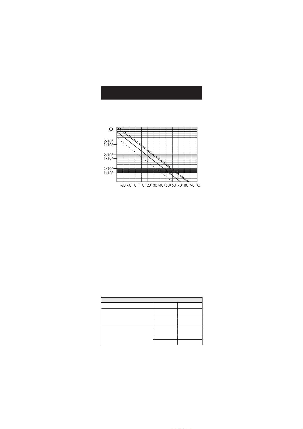
The resistance of glass electrodes partially depends on the temperature.
The lower the temperature, the higher the resistance. It takes more time
for the reading to stabilize if the resistance is higher. In addition, the
response time will suffer to a greater degree at temperatures below 25 ºC.
Since the resistance of the pH electrode is in the range of 50 – 200
Mohm, the current across the membrane is in the pico Ampere range.
Large currents can disturb the calibration of the electrode for many
hours.
For these reasons high humidity environments, short circuits and static
discharges are detrimental to a stable pH reading.
The pH electrode’s life also depends on the temperature. If constantly
used at high temperatures, the electrode life is drastically reduced.
Typical Electrode Life
Ambient Temperature 1 – 3 years
90 ºC Less than 4 months
120 ºC Less than 1 month
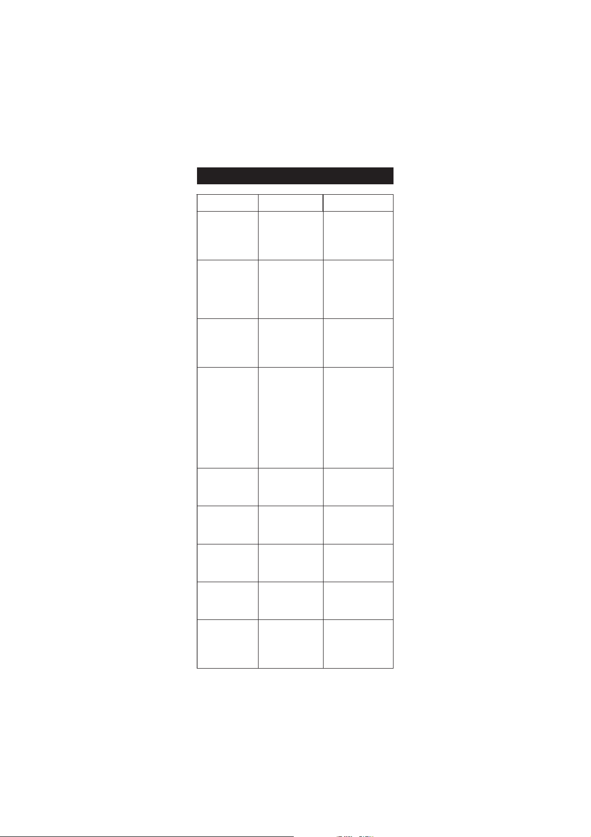
Alkaline Error
High concentrations of sodium ions interfere with readings in alkaline
solutions. The pH at which the interference starts to be significant
depends upon the composition of the glass. This interference is called
alkaline error and causes the pH to be underestimated. Hanna’s glass
formulations have the indicated characteristics.
Sodium Ion Correction for the Glass at 20-25 ºC
Concentration pH Error
0.1 Mol L-1 Na
1.0 Mol L-1 Na
H SENSITIVE GLASSH SENSITIVE GLASS
p
H SENSITIVE GLASS
pp
H SENSITIVE GLASSH SENSITIVE GLASS
+
+
13.00
13.50
14.00
12.50
13.00
13.50
14.00
0.10
0.14
0.20
0.10
0.18
0.29
0.40
38
Page 39

ACCESSORIESACCESSORIES
ACCESSORIES
ACCESSORIESACCESSORIES
pH BUFFER SOLUTIONS
HI 70004P pH 4.01 Buffer Sachets, 20 mL, 25 pcs
HI 70007P pH 7.01 Buffer Sachets, 20 mL, 25 pcs
HI 70010P pH 10.01 Buffer Sachets, 20 mL, 25 pcs
HI 7001L pH 1.68 Buffer Solution, 500 mL
HI 7004L pH 4.01 Buffer Solution, 500 mL
HI 7006L pH 6.86 Buffer Solution, 500 mL
HI 7007L pH 7.01 Buffer Solution, 500 mL
HI 7009L pH 9.18 Buffer Solution, 500 mL
HI 7010L pH 10.01 Buffer Solution, 500 mL
HI 8004L pH 4.01 Buffer Solution in FDA approved bottle, 500 mL
HI 8006L pH 6.86 Buffer Solution in FDA approved bottle, 500 mL
HI 8007L pH 7.01 Buffer Solution in FDA approved bottle, 500 mL
HI 8009L pH 9.18 Buffer Solution in FDA approved bottle, 500 mL
HI 8010L pH 10.01 Buffer Solution in FDA approved bottle, 500 mL
ELECTRODE STORAGE SOLUTIONS
HI 70300L Storage Solution, 500 mL
HI 80300L Storage Solution in FDA approved bottle, 500 mL
ELECTRODE CLEANING SOLUTIONS
HI 70000P Electrode Rinse Sachets, 20 mL, 25 pcs
HI 7061L General Cleaning Solution, 500 mL
HI 7073L Protein Cleaning Solution, 500 mL
HI 7074L Inorganic Cleaning Solution, 500 mL
HI 7077L Oil & Fat Cleaning Solution, 500 mL
HI 8061L General Cleaning Solution in FDA approved bottle, 500 mL
HI 8073L Protein Cleaning Solution in FDA approved bottle, 500 mL
HI 8077L Oil & Fat Cleaning Solution in FDA approved bottle, 500 mL
ELECTRODE REFILL ELECTROLYTE SOLUTIONS
HI 7071 3.5M KCl + AgCl Electrolyte, 4x30 mL, for single junction
electrodes
HI 7072 1M KNO3 Electrolyte, 4x30 mL
HI 7082 3.5M KCl Electrolyte, 4x30 mL, for double junction electrodes
HI 8071 3.5M KCl + AgCl Electrolyte in FDA approved bottle, 4x30
mL, for single junction electrodes
HI 8072 1M KNO3 Electrolyte in FDA approved bottle, 4x30 mL
HI 8082 3.5M KCl Electrolyte in FDA approved bottle, 4x30 mL, for
double junction electrodes.
39
Page 40
ORP PRETREATMENT SOLUTIONS
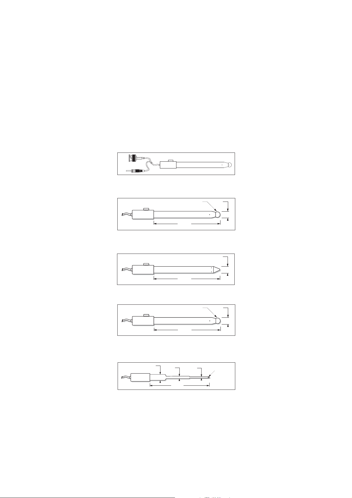
120 mm
4.7"
12 mm
0.5"
HI 1053
120 mm
4.7"
12 mm
0.5"
9.5mm DIA
0.37"
HI 1131
120 mm
4.7"
12 mm
0.5"
9.5mm DIA
0.37"
HI 1043
120 mm
12 mm
0.5"
5 mm
0.2"
3 mm
0.12"
3.0 mm DIA
0.12"
HI 1083
HI 7091L Reducing Pretreatment Solution, 500 mL
HI 7092L Oxidizing Pretreatment Solution, 500 mL
pH ELECTRODES
All electrodes with part numbers ending in P are supplied with a BNC
and pin connector and 1 m (3.3') cable, as shown below.
HI 1043P; Use: strong acid/alkali.
Glass-body, double junction, refillable, combination pH electrode.
"S" VERSION
HI 1053P; Use: emulsions.
Glass-body, triple ceramic, conic shape, refillable, combination pH electrode.
"S" VERSION
HI 1131P; Use: general purpose.
Glass-body, single junction, refillable, combination pH electrode.
"S" VERSION
HI 1083P; Use: biotechnology, micro titration.
Glass-body, micro, Viscolene, nonrefillable, combination pH electrode.
40
Page 41
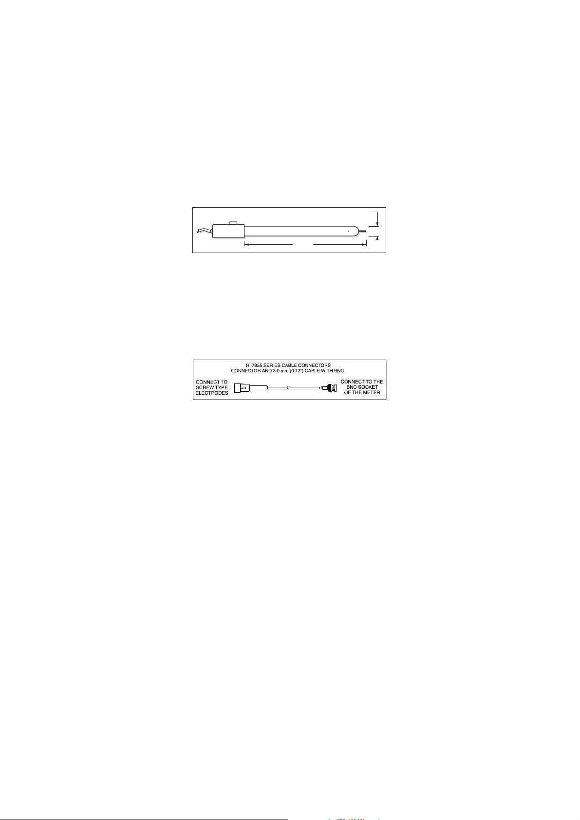
150 mm
5.9"
12 mm
0.5"
HI 3131
ORP ELECTRODES
HI 3131P; Use: titration.
Glass-body, refillable, combination platinum ORP electrode.
"S" VERSION
Consult the Hanna General Catalog for more electrodes with BNC and pin
connectors.
EXTENSION CABLE FOR SCREW-TYPE ELECTRODES
(SCREW TO BNC ADAPTER)
HI 7855/1 Extension cable 1 m (3.3') long
HI 7855/3 Extension cable 3 m (9.9') long
41
Page 42

OTHER ACCESSORIES
HI 710005 Voltage adapter from 115 VAC to 12 VDC (USA plug)
HI 710006 Voltage adapter from 230 VAC to 12 VDC (European
plug)
HI 710012 Voltage adapter from 240 VAC to 12 VDC (UK plug)
HI 710013 Voltage adapter from 230 VAC to 12 VDC (South Africa
plug)
HI 710014 Voltage adapter from 230 VAC to 12 VDC (Australia plug)
HI 76404N Electrode holder
HI 8427 pH and ORP electrode simulator with 1 m (3.3') coaxial
cable ending in female BNC connectors
HI 931001 pH and ORP electrode simulator with LCD and 1 m (3.3')
coaxial cable ending in female BNC connectors
HI 7662 Temperature probe with 1 m (3.3') cable
HI 92000 Windows® compatible software.
Windows® is registered Trademark of "Microsoft Co."
42
Page 43

RECOMMENDATIONS FOR USERS
Before using these products, make sure they are entirely suitable for the
environment in which they are used.
Operation of these instruments in residential areas could cause
unacceptable interferences to radio and TV equipment, requiring the
operator to follow all necessary steps to correct interferences.
The glass bulb at the end of the pH electrode is sensitive to electrostatic
discharges. Avoid touching this glass bulb at all times.
During operation, ESD wrist straps should be worn to avoid possible
damage to the electrode by electrostatic discharges.
Any variation introduced by the user to the supplied equipment may
degrade the instruments’ EMC performance.
To avoid electrical shock, do not use these instruments when voltages at
the measurement surface exceed 24 VAC or 60 VDC.
To avoid damage or burns, do not perform any measurement in
microwave ovens.
Hanna Instruments reserves the right to modify the design,
construction and appearance of its products without advance notice.
43
Page 44

Hanna Instruments Inc.
Highland Industrial Park
584 Park East Drive
Woonsocket RI 028985 USA
Local Sales and Customer Service office
Hanna Instruments United States Inc.
Highland Industrial Park
584 Park East Drive
Woonsocket RI 028985 USA
Tel. (800) 426 6287
Fax (401) 765 7575
www.hannainst.com/usa
Technical Support for customers
Telephone (800) 426 6287
Fax (401) 765 7575
E-mail tech@hannainst.com
Printed in Romania, EU
MAN2223 04/09
44
 Loading...