

Page 1
Instruction Manual
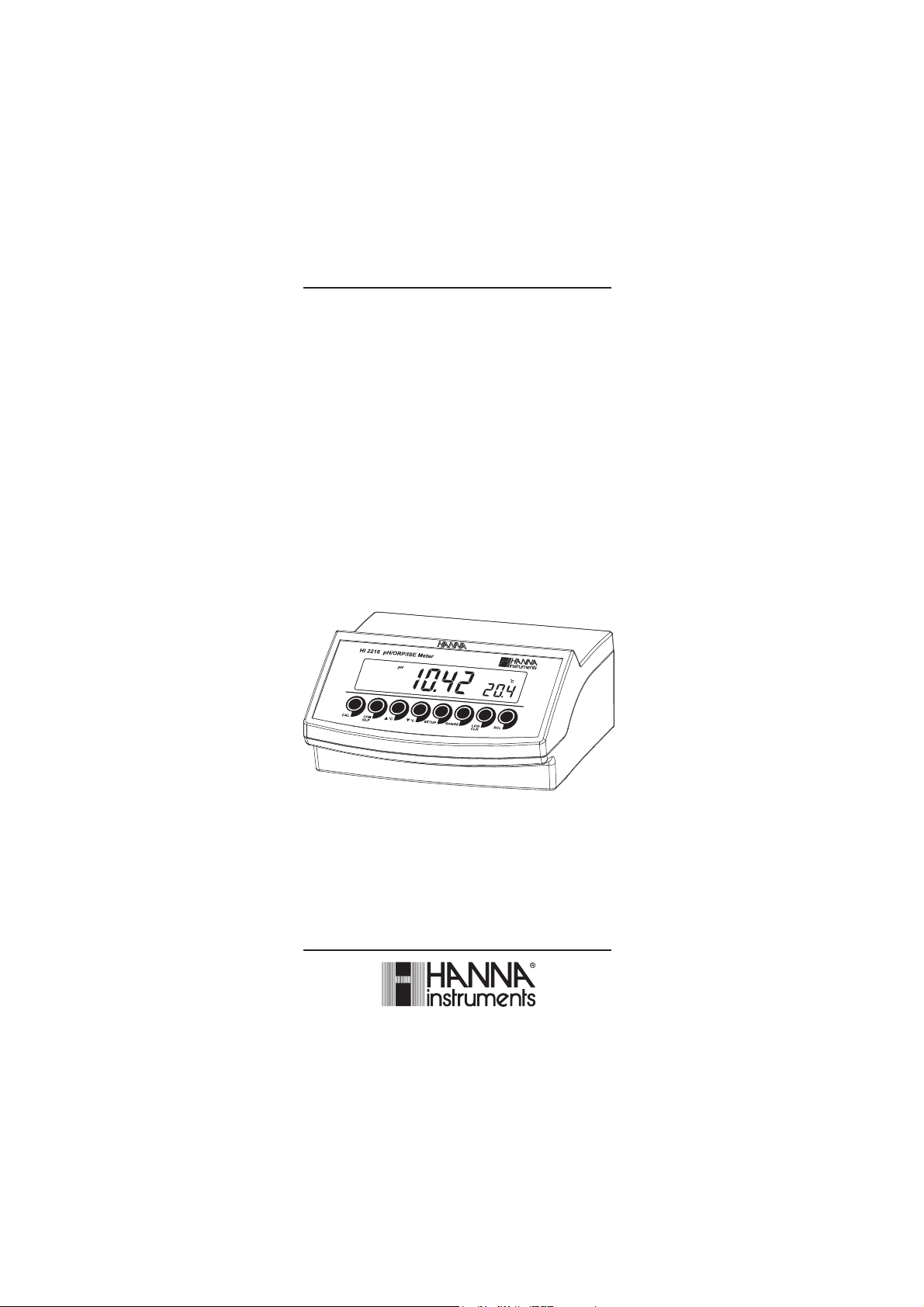
HI 2216
pH/mV/ISE/°C
Bench Meter
with Custom Buffers
and Interval Logging
www.hannainst.com
1
Page 2

Dear Customer,
Thank you for choosing a Hanna Instruments product.
Please read this instruction manual carefully before using this instrument.
This manual will provide you with the necessary information for correct
use of this instrument, as well as a precise idea of its versatility.
If you need additional technical information, do not hesitate to e-mail us
at tech@hannainst.com or view our worldwide contact list at
www.hannainst.com.
WARRANTYWARRANTY
WARRANTY
WARRANTYWARRANTY
HI 2216 is guaranteed for two years against defects in workmanship and
materials when used for their intended purpose and maintained according
to instructions. Electrodes and probes are guaranteed for six months. This
warranty is limited to repair or replacement free of charge.
Damage due to accidents, misuse, tampering or lack of prescribed
maintenance is not covered.
If service is required, contact the dealer from whom you purchased the
instrument. If under warranty, report the model number, date of
purchase, serial number and the nature of the problem. If the repair is
not covered by the warranty, you will be notified of the charges incurred.
If the instrument is to be returned to Hanna Instruments, first obtain a
Returned Goods Authorization number from the Technical Service
department and then send it with shipping costs prepaid. When shipping
any instrument, make sure it is properly packed for complete protection.
TABLE OF CONTENTSTABLE OF CONTENTS
TABLE OF CONTENTS
TABLE OF CONTENTSTABLE OF CONTENTS
WARRANTY ............................................................................................. 2
PRELIMINARY EXAMINATION ...................................................................... 3
GENERAL DESCRIPTION ............................................................................ 3
FUNCTIONAL DESCRIPTION ........................................................................ 4
SPECIFICATIONS ....................................................................................... 5
OPERATIONAL GUIDE ................................................................................ 6
pH CALIBRATION ...................................................................................... 9
pH BUFFER TEMPERATURE DEPENDENCE ................................................. 14
ISE CALIBRATION ................................................................................... 15
RELATIVE mV CALIBRATION .................................................................... 18
GOOD LABORATORY PRACTICE (GLP) ........................................................ 18
LOGGING FUNCTION ............................................................................... 23
SETUP .................................................................................................. 28
TEMPERATURE CALIBRATION (for technical personnel only) .......................... 33
mV CALIBRATION (for technical personnel only) .......................................... 34
PC INTERFACE ....................................................................................... 35
ELECTRODE CONDITIONING & MAINTENANCE ............................................. 40
TROUBLESHOOTING GUIDE ..................................................................... 43
TEMPERATURE CORRELATION FOR pH SENSITIVE GLASS ............................. 44
ACCESSORIES ........................................................................................ 45
2
Page 3

PRELIMINARY EXAMINATIONPRELIMINARY EXAMINATION
PRELIMINARY EXAMINATION
PRELIMINARY EXAMINATIONPRELIMINARY EXAMINATION
Remove the instrument from the packing material and examine it carefully
to make sure that no damage has occurred during shipping. If there is any
damage, notify your Dealer or the nearest Hanna Customer Service Center.
Each instrument is supplied with:
• HI 1131B Glass-body Combination pH Electrode with 1 m (3.3')
Cable
• HI 7662 Temperature Probe
• HI 76404N Electrode Holder
• pH 4.01 & 7.01 Buffer Solutions (20 mL each)
• HI 7071 Electrolyte Solution
• HI 700661 Cleaning Solution
• 12VDC Power Adapter
• Instruction Manual
Note: Save all packing material until you are sure that the instrument
functions correctly. All defective items must be returned in the
original packing with the supplied accessories.
GENERAL DESCRIPTIONGENERAL DESCRIPTION
GENERAL DESCRIPTION
GENERAL DESCRIPTIONGENERAL DESCRIPTION
The HI 2216 is state of the art, heavy-duty pH, mV, ISE meter designed
to provide laboratory results and accuracy under harsh industrial
conditions.
HI 2216 can also measure Oxidation Reduction Potential (ORP) in mV
range.
Relative mV feature is also provided.
pH measurements are compensated for temperature effect manually or
automatically with the HI 7662 temperature probe.
Up to a five-point pH calibration can be performed using seven standard
buffers. In addition, two custom buffers can be used during calibration.
Up to a two-point ISE calibration can be performed using five standard
solutions.
The GLP feature provides data consistency.
A calibration due alarm can be set to alert the user that too much time
elapsed since the last pH calibration.
Data can be stored in meter’s memory for later retrieval.
An USB connection ensures communication with a PC.
The meter’s memory can hold 200 manually logged points and 500 lot
logging points.
3
Page 4
FUNCTIONAL DESCRIPTIONFUNCTIONAL DESCRIPTION
FUNCTIONAL DESCRIPTION
FUNCTIONAL DESCRIPTIONFUNCTIONAL DESCRIPTION
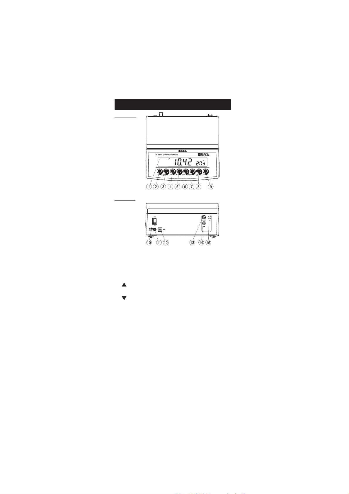
Front Panel
Rear Panel
1) Liquid Crystal Display (LCD).
2) CAL key, to enter and exit calibration mode.
3) CFM/GLP key, to confirm calibration, different values or to display
Good Laboratory Practice information.
4) ºC key, to manually increase temperature value or other
parameters.
5) ºC key, to manually decrease temperature value or other
parameters.
6) SETUP key, to enter/exit SETUP mode.
7) RANGE key, to select measurement range, switch to focused data in
SETUP or toggle between buffer value and temperature during
calibration.
8) LOG/CLR key, to store a value into memory, to clear pH calibration,
or to delete log records.
9) RCL key, memory recall.
10) ON/OFF switch.
11) Power supply socket.
12) USB connector.
13) BNC electrode connector.
14) Temperature probe socket.
15) Electrode reference socket.
4
Page 5
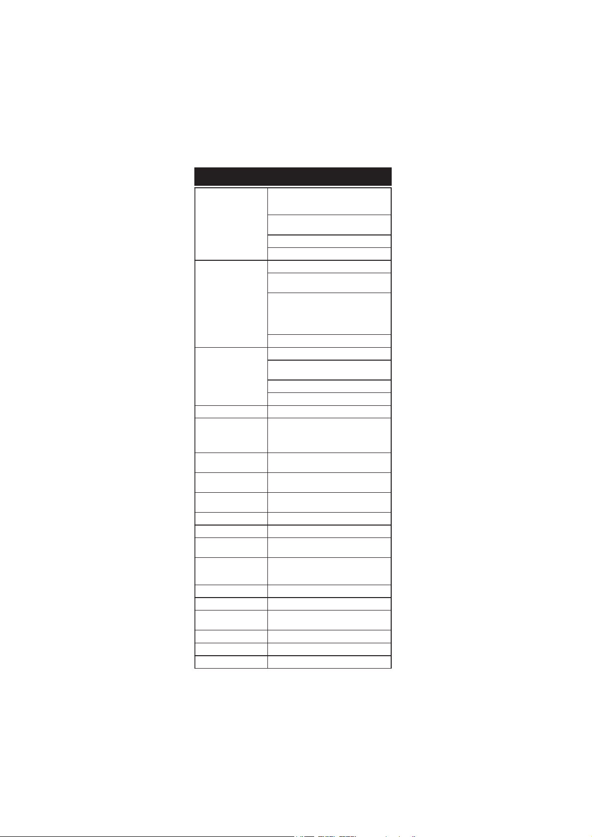
EGNAR
Hp0.61ot0.2–
Hp00.61ot00.2–
Hp000.61ot000.2–
)PRO(Vm9.999±
)PRO(Vm0002±
mpp09991ot100.0
)F°0.842ot0.4-(Cº0.021ot0.02–
NOITULOSER
Hp100.0,Hp10.0,Hp1.0
)PRO&ESI()Vm9.999±(Vm1.0
)PRO&ESI()Vm0002±(Vm1
)mpp999.1ot(100.0
)mpp99.91ot(10.0
)mpp9.991ot(1.0
)mpp9991ot(1
)mpp09991ot(01
Cº1.0
YCARUCCA
F°86/C°02@
Hp200.0±,Hp10.0±,Hp1.0±
)Vm9.999±(Vm2.0±
)Vm0002±(Vm1±
SF%5.0±
)rorreeborpgnidulcxe(Cº2.0±
egnartesffoVmleR Vm0002±
noitarbilaCHp
,noitarbilactniop5otpu,citamotuA
elbaliavasreffubdradnats7
,)54.21,10.01,81.9,10.7,68.6,10.4,86.1(
sreffubmotsuc2dna
noitarbilaCESI
sreffub5,stniop2ro1,citamotuA
)mpp0001,001,01,1,1.0(elbaliava
erutarepmeT
noitasnepmoc
ro)eborp2667IHhtiw(citamotuA
Cº0.021ot0.02–morflaunam
edortcelEHp
,B1311IH ,noitcnujelgnis,ydob-ssalg
)dedulcni(rotcennocCNB,elballifer
eborperutarepmeT )dedulcni(2667IH
ecnadepmitupnI 01
21
smho
erutaefgoL
sdrocer002
dnamednogol
erutaeflavretnIgoL
,)bAtS(gniggolytilibatS
ces03,01,5
nim081,021,06,03,51,01,5,2,1
noitacinummocCP BSUdetalosi-otpO
ylppusrewoP )dedulcni(retpadaCDV21
tnemnorivnE
)Fº221–23(Cº05–0
gnisnednoc-nonHR%59.xam
snoisnemiD )”3.4x7.8x2.9(mm901x222x532
thgieW )bl9.2(gK3.1
ytnarraW sraey2
SPECIFICATIONSSPECIFICATIONS
SPECIFICATIONS
SPECIFICATIONSSPECIFICATIONS
5
Page 6
OPERATIONAL GUIDEOPERATIONAL GUIDE
OPERATIONAL GUIDE
OPERATIONAL GUIDEOPERATIONAL GUIDE
POWER CONNECTION
Plug the 12 VDC adapter into the power supply socket.
Notes: • This instrument uses non volatile memory to retain the pH,
mV, temperature calibrations and all other settings, even
when unplugged.
• Make sure a fuse protects the main line.
ELECTRODE AND PROBE CONNECTIONS
For pH or ORP measurements connect an electrode with internal reference
to the BNC connector on the back of the instrument.
For electrodes with a separate reference connect the electrode’s BNC to the
BNC connector and the reference electrode plug to the reference socket.
For temperature measurements and automatic temperature compensation
connect the temperature probe to the appropriate socket.
INSTRUMENT START-UP
• Turn the instrument on by pressing the ON/OFF switch located on
the rear panel.
• All LCD tags are displayed and a beep is sounded while the instruments
perform a self test.
• The instrument will display “LoAd” message and “ ” blinking until
initialization is complete.
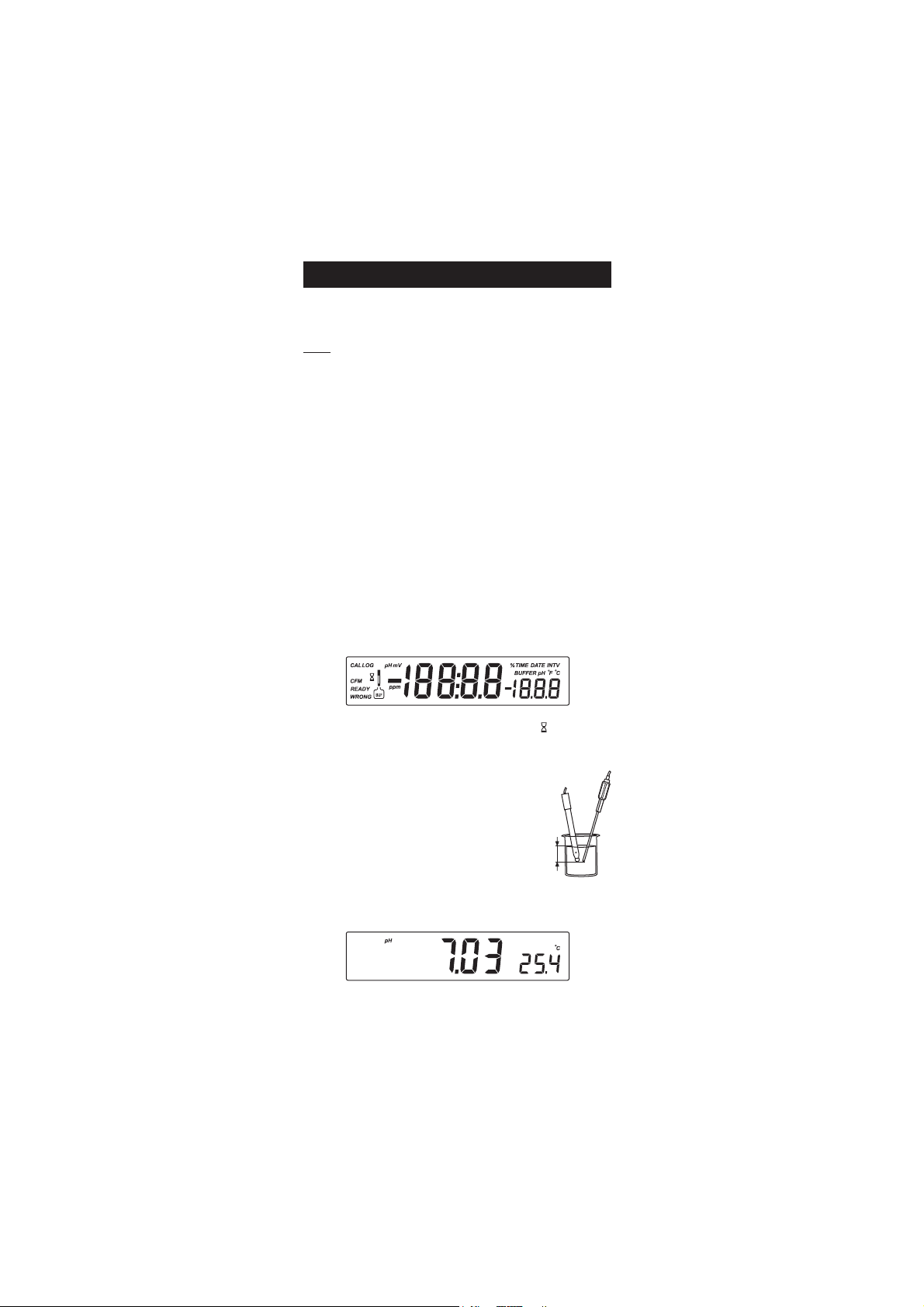
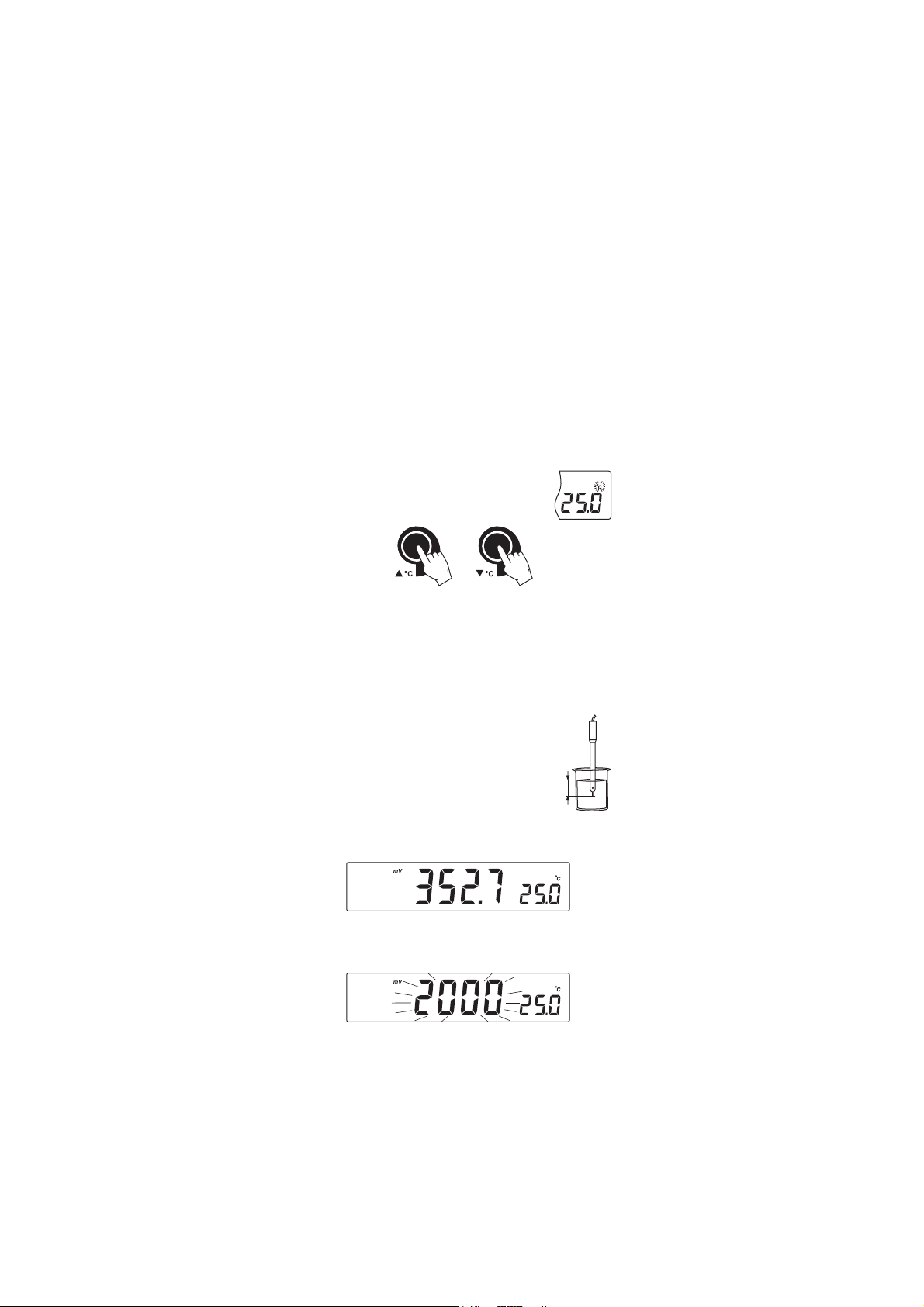
pH MEASUREMENTS
Make sure the instrument has been calibrated before
taking pH measurements.
• Submerse the electrode tip and the temperature
probe approximately 3 cm (1¼”) into the sample
to be tested and stir gently. Allow time for the
3 cm
(1¼")
electrode to stabilize.
• The pH is displayed on the primary LCD and the temperature on the
secondary LCD.
• If the reading is out of range, the closest full-scale value will be
displayed blinking on the primary LCD.
6
Page 7
If measurements are taken successively in different samples, it is recommended
to rinse the electrode thoroughly with deionized water or tap water and
then with some of the next sample to prevent cross-contamination.
The pH reading is affected by temperature. In order to measure the pH
accurately, the temperature effect must be compensated for. To use the
Automatic Temperature Compensation feature, connect and submerse
the HI 7662 temperature probe into the sample as close as possible to
the electrode and wait for a few seconds.
If the temperature of the sample is known, manual temperature
compensation can be used by disconnecting the temperature probe.
The display will show the last temperature reading with the “ºC” tag blinking.
The temperature can now be adjusted with the
ARROW keys (from -20.0 ºC to 120.0 ºC).
mV/ORP MEASUREMENTS
An optional ORP electrode must be used to perform ORP measurements
(see Accessories).
Oxidation-Reduction Potential (REDOX) measurements provide the
quantification of the oxidizing or reducing power of the tested sample.
The surface of the ORP electrode must be clean and smooth in order to
obtain an accurate measurement.
• Press RANGE to enter mV range.
• Submerse the tip of the ORP electrode 3 cm (1¼”)
into the sample to be tested and allow a few
seconds for the reading to stabilize.
3 cm
(1¼")
• The instrument displays the mV reading on the primary LCD and the
temperature on the secondary LCD.
• If the reading is out of range, the closest full-scale value will be
displayed blinking on the primary LCD.
7
Page 8
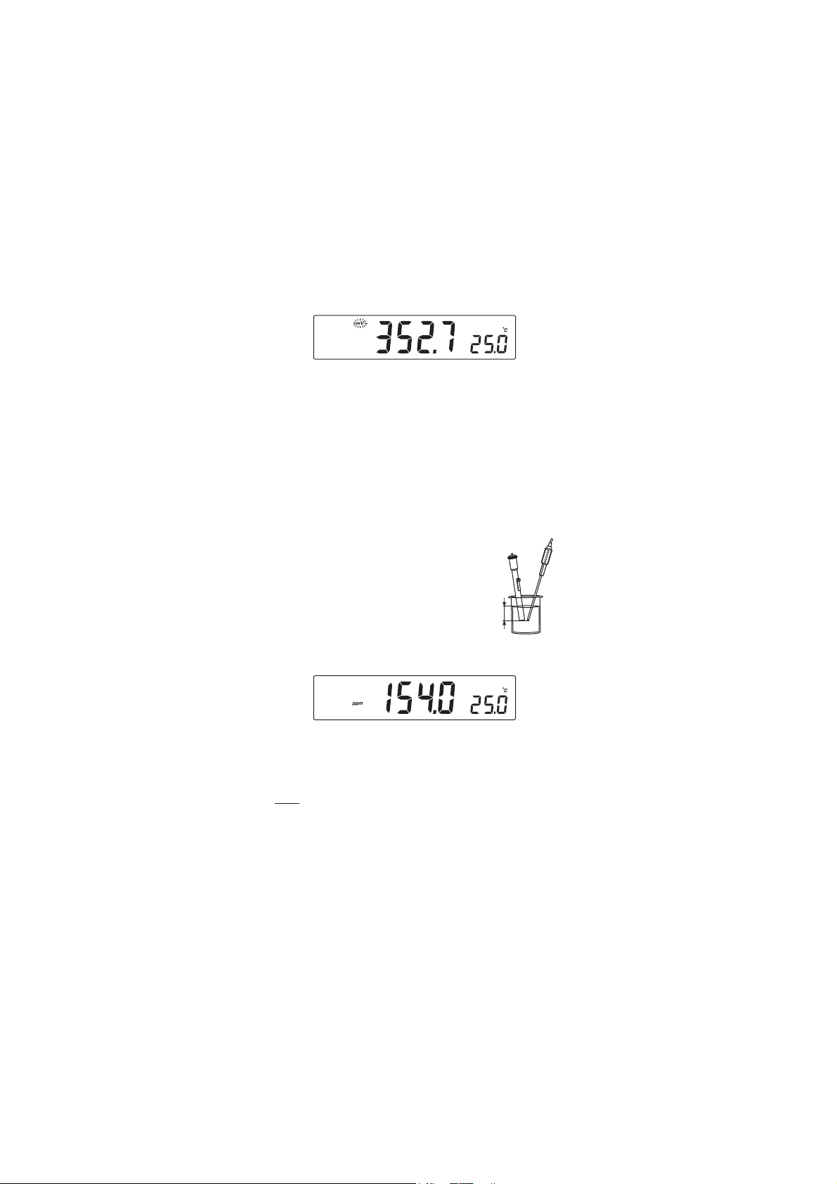
RELATIVE mV MEASUREMENTS
• Press RANGE until “rEL” message and “mV” tag are displayed for
one second. After one second the temperature will be displayed on
the secondary LCD and the “mv” tag will blink.
The reading displayed by the instrument is equal to the difference
between the current mV input value and relative mV offset established in
the relative mV calibration.
ISE MEASUREMENT
To perform ion concentration measurements, connect an optional ISE
electrode to the instrument input (BNC or BNC and REF if separate
reference electrode is used). Enter the ISE mode by pressing RANGE key
until the display changes to ppm. Select the corresponding ion charge in
the SETUP menu.
Submerse the ISE electrode (reference electrode) and
temperature probe (3 cm/1¼”) into the sample to
be tested and wait a few seconds for the reading to
stabilize.
The ppm reading will be displayed on the primary
3 cm
(1¼")
LCD and the current temperature value on the
secondary LCD.
In order to take accurate ISE measurements, make sure that the
appropriate ion charge was set in the SETUP menu and the instrument
was calibrated (see ISE CALIBRATION for details, page 15).
Notes: • When the reading is out of range, the display will flash the
closest full-scale value.
• The instrument will display “----” on the primary LCD if it is
not calibrated. Perform at least a one-point calibration if the
ion charge is -1, 1, -2, 2 or a two-point calibration for the
“undF” option selected in SETUP menu in order to take ISE
measurements.
8
Page 9

TEMPERATURE MEASUREMENTS
Connect the HI 7662
appropriate socket and turn the instrument on.
Submerse the temperature
and allow the reading on the secondary LCD to stabilize.
Calibrate the instrument frequently, especially if high accuracy is
required.
The instrument should be recalibrated:
• Whenever the pH electrode is replaced.
• At least once a week.
• After testing aggressive chemicals.
• If “CAL” “INTV” tags are blinking during measurement.
Every time you calibrate the instrument use fresh buffers and perform an
electrode Cleaning Procedure (see page 42).
PREPARATION
Pour small quantities of the buffer solutions into clean beakers. If
possible, use plastic or glass beakers to minimize any EMC interferences.
For accurate calibration and to minimize cross-contamination, use two
beakers for each buffer solution. One for rinsing the electrode and one for
calibration.
If you are measuring in the acidic range, use pH 7.01 or 6.86 as first
buffer and pH 4.01 as second buffer. If you are measuring in the alkaline
range, use pH 7.01 or 6.86 as first buffer and pH 10.01 or 9.18 as
second buffer.
PROCEDURE
Calibration can be performed up to five-points.
For accurate measurements a three-point calibration is recommended.
The calibration buffer can be selected from the calibration buffer list that
includes the custom buffers and the memorized standard buffers:
• pH 1.68, 4.01, 6.86, 7.01, 9.18, 10.01 and 12.45.
temperature probe to the
probe
into the sample
pp
H CALIBRATIONH CALIBRATION
p
H CALIBRATION
pp
H CALIBRATIONH CALIBRATION
9
Page 10
The custom buffers allow the user to calibrate in a buffer solution different
BUF
from a standard one. Up to two custom buffers can be set in SETUP menu
(see page 28). Each custom buffer value can be changed in a ±1.0 pH
window around the set value, during calibration, when it is selected; the
“BUFFER pH” tag will blink.
The instruments will automatically skip the buffer used during calibration
and the buffers which are in a ±0.2 pH window, around one of the
calibrated buffers.
All new calibrations will override existing stored calibration data in a
±0.2 pH window. The slopes adjacent to the new points will be reevaluated.
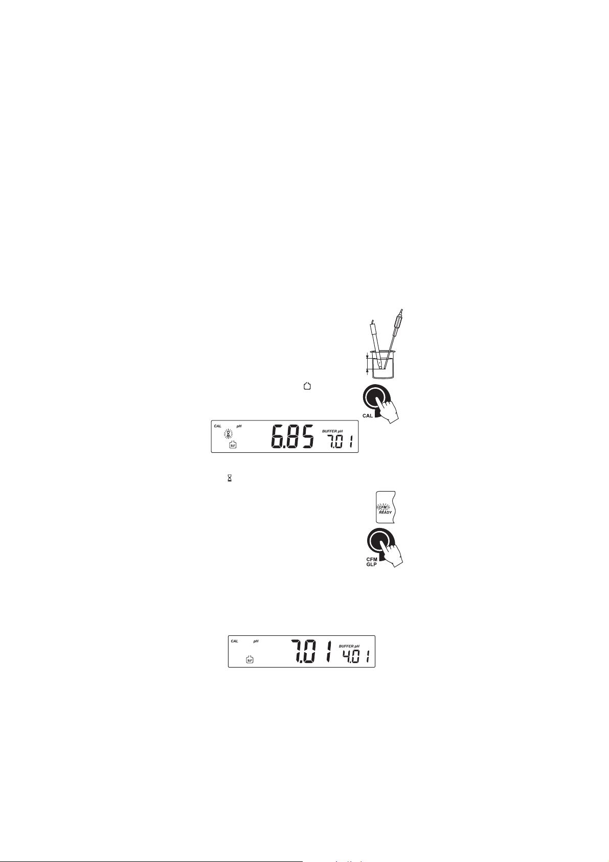
FIVE-POINT CALIBRATION
• Submerse the pH electrode and the temperature
probe approximately 3 cm (1¼”) into a buffer
solution and stir gently. The temperature probe
should be close to the pH electrode.
• Press CAL. The “CAL” and “
” tags will
3 cm
(1¼")
appear and the “7.01” buffer will be displayed
on the secondary LCD.
• If necessary, press the ARROW keys to select a different buffer value.
• The “ ” tag will blink on the LCD until the reading is stable.
• When the reading is stable and close to the selected
buffer, the “READY” tag will be displayed and the
“CFM” tag will blink.
• Press CFM to confirm calibration.
• The calibrated value will be displayed on the primary
LCD and the second expected buffer value on the
secondary LCD.
• After the first calibration point is confirmed, submerse the pH
electrode and the temperature probe approximately 3 cm (1¼”)
into the second buffer solution and stir gently. The temperature
probe should be close to the pH electrode.
• If necessary, press the ARROW keys to select a different buffer value.
10
Page 11
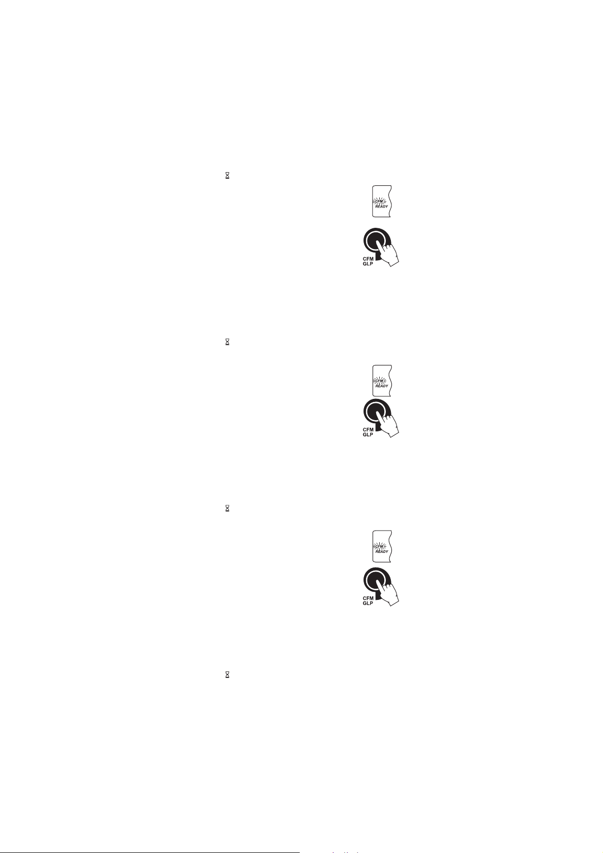
• The “ ” tag will blink on the LCD until the reading is stable.
• When the reading is stable and close to the selected
buffer, the “READY” tag will be displayed and the
“CFM” tag will blink.
• Press CFM to confirm calibration.
• The calibrated value is then displayed on the
primary LCD and the third expected buffer value on
the secondary LCD.
• After the second calibration point is confirmed, submerse the pH
electrode and the temperature probe approximately 3 cm (1¼”) into
the next buffer solution and stir gently. The temperature probe
should be close to the pH electrode.
• If necessary, press the ARROW keys to select a different buffer value.
• The “ ” tag will blink on the LCD until the reading is stable.
• When the reading is stable and close to the selected buffer, the
“READY” tag will be displayed and the “CFM” tag
will blink.
• Press CFM to confirm calibration.
• The calibrated value is then displayed on the
primary LCD and the fourth expected buffer value
on the secondary LCD.
• After the third calibration point is confirmed, submerse the pH
electrode and the temperature probe approximately 3 cm (1¼”) into
the next buffer solution and stir gently. The temperature probe should
be close to the pH electrode.
• If necessary, press the ARROW keys to select a different buffer value.
• The “ ” tag will blink on the LCD until the reading is stable.
• When the reading is stable and close to the selected buffer, the
“READY” tag will be displayed and the “CFM” tag
will blink.
• Press CFM to confirm calibration.
• The calibrated value is then displayed on the
primary LCD and the fifth expected buffer value on
the secondary LCD.
• After the fourth calibration point is confirmed, submerse the pH
electrode and the temperature probe approximately 3 cm (1¼”) into
the next buffer solution and stir gently. The temperature probe
should be close to the pH electrode.
• If necessary, press the ARROW keys to select a different buffer value.
• The “ ” tag will blink on the LCD until the reading is stable.
11
Page 12

• When the reading is stable and close to the selected
buffer, the “READY” tag will be displayed and the
“CFM” tag will blink.
• Press CFM to confirm the fifth calibration point.
• The instrument stores the calibration value and
returns to normal measurement mode.
FOUR, THREE OR TWO-POINT CALIBRATION
• Proceed as described in “FIVE-POINT CALIBRATION” section.
• Press CAL after the fourth, third or second calibration point was
confirmed. The instrument will memorize the calibration data and
return to measurement mode.
ONE-POINT CALIBRATION
Two SETUP selectable options are available: “Pnt” and “OFFS”.
If the “Pnt” option is selected, the new calibration point overrides an
existing one. The adjacent slopes will be reevaluated.
If the “OFFS” option is selected, an electrode offset correction is performed.
The adjacent slopes will remain unchanged.
• Proceed as described in “FOUR, THREE or TWO-POINT CALIBRATION”
section.
• Press CAL after the first calibration point was confirmed. The
instrument will memorize the one-point calibration data and will
return to measurement mode.
Notes: • If the value measured by the instrument is not close to the
selected buffer, “WRONG” “ ” and “WRONG” “ ” tags
will blink alternately. Check if the correct buffer has been
used, or clean the electrode by following the Cleaning Procedure
(see page 42). If necessary, change the buffer or the electrode.
• When a custom buffer is displayed, the “BUFFER pH” tag
blinks. To change the custom buffer value in accordance with
the buffer temperature proceed as described in “WORKING
WITH CUSTOM BUFFERS” (see page 13).
• If the buffer temperature or the manual temperature
exceeds the temperature limits of the buffer, “WRONG” tag
and temperature reading will blink.
• If “WRONG”, “BUFFER pH” tags and “OLD” message are
displayed blinking on the secondary LCD line, an inconsistency
between new and previous (old) calibration is detected.
12
Page 13
Clear calibration parameters and proceed with calibration
from the current calibration point. The instrument will keep
all confirmed values during current calibration.
• To clear calibration parameters for all uncalibrated buffers
starting with current buffer, press CLR. The calibration will
continue from the current point. If
this procedure is performed while calibrating in the first calibration point, the
instrument returns to measurement
mode.
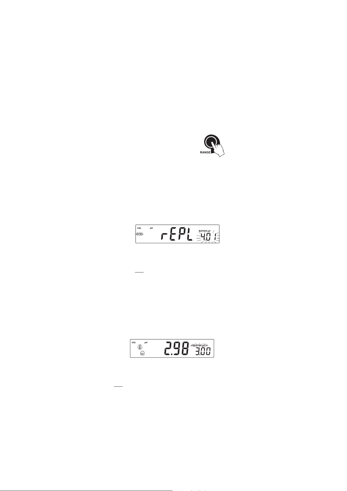
• Press RANGE to toggle between pH buffer, calibration
buffer number and temperature reading.
• Each time a buffer is confirmed, the new calibration data
replaces the old data for the coresponding buffer. If current
buffer has no previous data stored and the calibration is not
full (five buffers), the current buffer is added to the existing
calibration. If the existing calibration is full, the instrument
asks which buffer to replace.
Press the ARROW keys to select another buffer to be replaced.
Press CFM to confirm the buffer that will be replaced.
Press CAL to leave calibration without replacing.
Note: If the replaced buffer is outside the ±0.2 pH window,
around each of the calibrated buffers, it is possible to
select this buffer for next calibration during current
calibration.
WORKING WITH CUSTOM BUFFERS
If a custom buffer was set in SETUP menu, it can be selected during
calibration by pressing the ARROW keys. The “BUFFER pH” tag will
blink.
Press SETUP if you want to adjust the buffer value. The buffer value will
start blinking.
Use the ARROW keys to change the buffer value.
After 5 seconds, the buffer value is updated. Press SETUP if you want to
change it again.
Note: Custom buffer value can be adjusted in a ±1.00 pH window,
around the set value.
13
Page 14
PMET SREFFUBHp
Cº Fº 86.1 10.4 68.6 10.7 81.9 10.01 54.21
0 23 76.1 10.4 89.6 31.7 64.9 23.01 83.31
5 14 76.1 00.4 59.6 01.7 93.9 42.01 81.31
01 05 76.1 00.4 29.6 70.7 33.9 81.01 99.21
51 95 76.1 00.4 09.6 50.7 72.9 21.01 08.21
02 86 86.1 00.4 88.6 30.7 22.9 60.01 26.21
52 77 86.1 10.4 68.6 10.7 81.9 10.01 54.21
03 68 86.1 20.4 58.6 00.7 41.9 69.9 92.21
53 59 96.1 30.4 48.6 99.6 11.9 29.9 31.21
04 401 96.1 40.4 48.6 89.6 70.9 88.9 89.11
54 311 07.1 50.4 38.6 89.6 40.9 58.9 38.11
05 221 17.1 60.4 38.6 89.6 10.9 28.9 07.11
55 131 27.1 80.4 48.6 89.6 99.8 97.9 75.11
06 041 27.1 90.4 48.6 89.6 79.8 77.9 44.11
56 941 37.1 11.4 48.6 99.6 59.8 67.9 23.11
07 851 47.1 21.4 58.6 99.6 39.8 57.9 12.11
57 761 67.1 41.4 68.6 00.7 19.8 47.9 01.11
08 671 77.1 61.4 78.6 10.7 98.8 47.9 00.11
58 581 87.1 71.4 78.6 20.7 78.8 47.9 19.01
09 491 97.1 91.4 88.6 30.7 58.8 57.9 28.01
59 302 18.1 02.4 98.6 40.7 38.8 67.9 37.01
pp
H BUFFER TEMPERATUREH BUFFER TEMPERATURE
p
H BUFFER TEMPERATURE
pp
H BUFFER TEMPERATUREH BUFFER TEMPERATURE
DEPENDENCEDEPENDENCE
DEPENDENCE
DEPENDENCEDEPENDENCE
The temperature has an effect on pH. The calibration buffer solutions are
affected by temperature changes to a lesser degree than normal solutions.
During calibration the instrument will automatically calibrate to the pH
value corresponding to the measured or set temperature.
During calibration the instrument will display the pH buffer value at 25 ºC.
14
Page 15
1
BUF
II
SESE
CALIBRATION CALIBRATION
I
SE
CALIBRATION
II
SESE
CALIBRATION CALIBRATION
It is recommended to calibrate the instrument frequently, especially if
high accuracy is required.
The ppm range should be recalibrated:
• Whenever the ISE electrode is replaced.
• When the ion charge is changed in SETUP menu.
• At least once a day.
• After testing agressive chemicals.
• When calibration is expired - “CAL” “INTV” tags blink (if feature is
enabled).
Due to electrode conditioning time, the electrode must be kept submersed
a few seconds to stabilize.
PROCEDURE
Select the proper ion charge in SETUP menu (see SETUP for details, page 28).
Note: If “undF” option is selected in SETUP menu, calibration must be
performed at two points. Otherwise “----” message will be
displayed on the LCD.
Pour small quantities of the calibration solutions into clean beakers. If
possible, use plastic beakers to minimize any EMC interferences.
For accurate calibration and to minimize cross-contamination, use two
beakers for each calibration solution. One for rinsing the electrode and
one for calibration.
Note: ISA needs to be added to all calibration solutions. See sensor
manual.
The instrument offers a choice of six standard solutions: 0.1, 1, 10, 100,
1000, 10000 ppm and calibration up to two points. Standards should
bracket the working range.
Remove the protective cap from the ISE electrode.
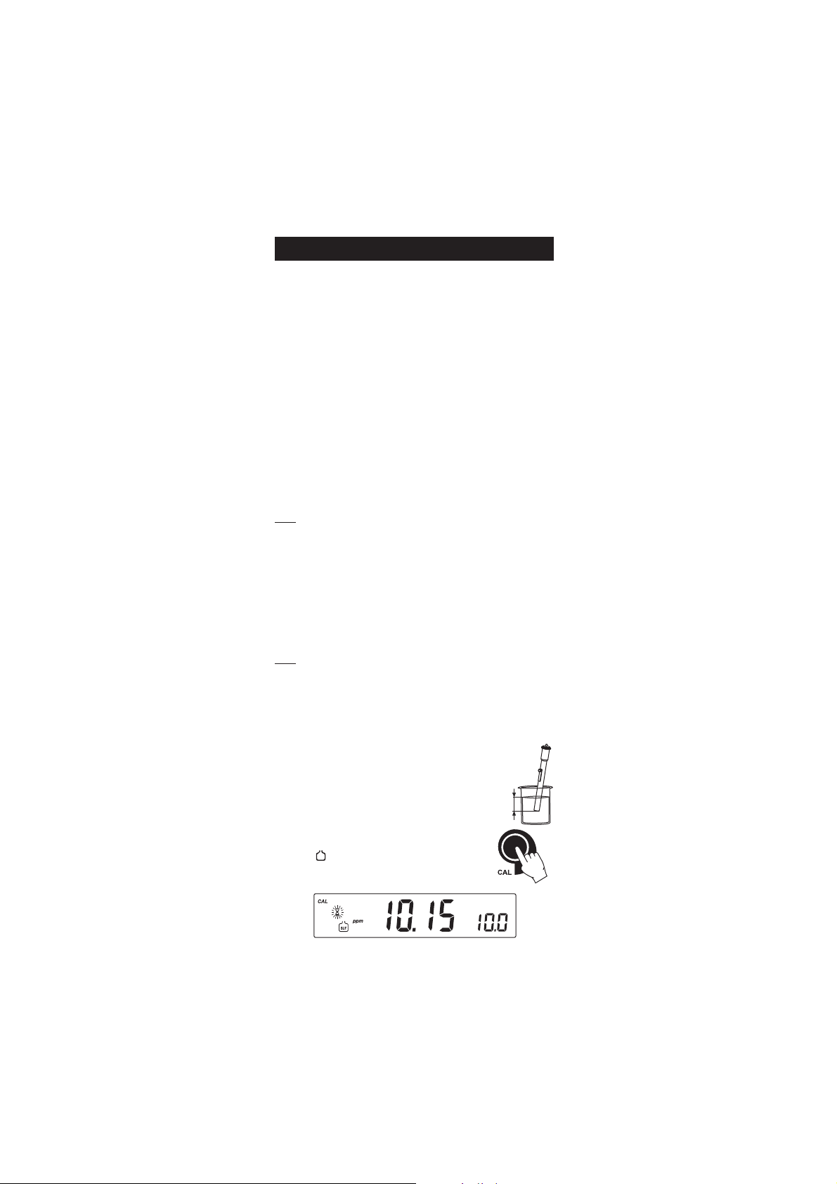
TWO-POINT CALIBRATION
• Submerse the ISE electrode approximately 3 cm
(1¼”) into the selected solution and stir gently.
3 cm
(1¼")
• Press CAL. The primary LCD will display the ppm
value using the current offset and slope. The “CAL”
and “
” tags will appear and “10.0” ppm
standard will be displayed on the secondary LCD.
15
Page 16

• If necessary, press the ARROW keys to select a different standard
BUF
BUF
value.
• The “ ” tag will blink on the LCD until the reading
is stable.
• When the reading is stable and close to the selected
standard, the “READY” tag will be displayed and
the “CFM” tag will blink.
• Press CFM to confirm calibration.
• The calibrated value will be displayed on the primary LCD and the
second expected standard value on the secondary LCD.
Note: The instrument will automatically skip the standard used for the
first point.
• After the first calibration point is confirmed, submerse the ISE electrode
approximately 3 cm (1¼”) into the second calibration solution.
• If necessary, press the ARROW keys to select a different standard
value.
• The “ ” tag will blink on the LCD until the reading
is stable.
• When the reading is stable and close to the selected
standard, the “READY” tag will be displayed and
the “CFM” tag will blink.
• Press CFM to confirm calibration.
• The instrument stores the calibration value and returns to normal
measurement mode.
Notes: • If the mV value is out of the mV range (±2000), “WRONG”
“
” and “WRONG” “ ” tags will blink alternately. In this
case, check if the correct standard has been used.
• If the new slope is out of the slope window, “WRONG” “
”
and “WRONG” “ ” tags will blink alternately. In this case,
check if the correct standard has been used.
Slope window is between ±20 mV and ±120 mV if
ion charge is not specified (undF option in SETUP menu)
or between 50% and 120% of default slope for the
corresponding ion charge.
16
Page 17

Default slope value (mV/decade):
–59.16 (monovalent cation) - ion charge is 1
59.16 (monovalent anion) - ion charge is –1
–29.58 (divalent cation) - ion charge is 2
29.58 (divalent anion) - ion charge is –2
100 - ion charge is “undF”
• Press CLR during calibration if you want to clear calibration
values. The instrument will display “CLR” message and will
return to measurement mode.
• The calibration needs to be cleared when a new electrode is
attached to the meter.
• The instrument will display “----” on the primary LCD if it is
not calibrated or after all calibrations are cleared.
• Press RANGE to display the temperature reading on
the LCD during calibration.
ONE-POINT CALIBRATION
• Press CAL after first calibration point was confirmed. The instrument
memorizes the one-point calibration information and returns to
measurement mode.
• Press RANGE to display the temperature reading on
the LCD during calibration.
17
Page 18

RELATIVE RELATIVE
RELATIVE
RELATIVE RELATIVE
• Press CAL when the instrument is in RELATIVE mV measurement
mode. The “mV” and “ ” tags will be displayed. Absolute mV is
displayed on the primary LCD and “AbS” message is displayed on the
secondary LCD.
• When the absolute reading is stable and in measurement range, the
instrument asks for confirmation.
• If the reading is out of range, “WRONG” tag will be displayed.
• Press CFM to confirm the absolute value. The instrument will display
“0.0 mV“ on the primary LCD and “rEL” message on the secondary
LCD. In this moment the relative mV offset is equal to absolute mV
reading.
• Use the ARROW keys if you want to change the displayed relative
mV value.
• Press CFM to confirm the relative mV value. The relative mV
offset is displayed on the primary LCD. The instrument returns to
measurement mode.
Note: The relative mV value can be changed only inside the relative mV
offset window (± 2000 mV).
mm
V CALIBRATIONV CALIBRATION
m
V CALIBRATION
mm
V CALIBRATIONV CALIBRATION
GOOD LABORATORY PRACTICE (GLP)GOOD LABORATORY PRACTICE (GLP)
GOOD LABORATORY PRACTICE (GLP)
GOOD LABORATORY PRACTICE (GLP)GOOD LABORATORY PRACTICE (GLP)
GLP is a set of functions that allows storage and retrieval of data
regarding the maintenance and status of the electrode.
All data regarding pH, Rel mV or ISE calibration is stored for the user to
review when necessary.
EXPIRED CALIBRATION
This instrument allows the user to set the number of days before the next
required calibration. This value can be set from 1 to 7 days. The default
setting is off (disabled). The “CAL” “INTV” tags will start blinking to
warn the user that the instrument should be recalibrated.
For example, if a 4 days time out has been selected, the instrument will
issue the alarm exactly 4 days after the last calibration.
If the expiration value is changed (e.g. to 5 days), then the alarm will
be immediately recalculated and appear 5 days after the last
calibration.
18
Page 19

Notes: • When the instrument is not calibrated or calibration is cleared
(default values loaded) there is no “expired calibration”,
and the display always shows the “CAL” “INTV” tags blinking.
• When an abnormal condition in the RTC is detected, the
instrument forces the “expired calibration” status.
pH CALIBRATION DATA
Calibration data is stored automatically after a successful calibration.
To view the pH calibration data, press GLP while in measurement mode.
The instruments will display the time (hh:mm) of the last calibration.
Use the ARROW keys to scroll through the calibration data:
• The date (yyyy.mm.dd).
• The pH calibration offset.
• The pH calibration slope (the GLP slope is the average of the calibration
slopes; the percentage is referred to the ideal value of 59.16 mV/pH).
• The pH calibration buffers in calibrating order and with the selected
resolutions at calibration moment.
The first pH calibration buffer:
The second pH calibration buffer:
19
Page 20

The third pH calibration buffer:
The fourth pH calibration buffer:
The fifth pH calibration buffer:
Notes: • The “OLd” message displayed beside the pH value means
that this buffer was not used during last calibration. Press
and hold down SETUP if you want to see calibration date
(or time, if old calibration was performed on the same day
as the current calibration).
• For each custom buffer used in calibration, the “BUFFER
pH” tag will blink.
• If “no bUF” message appears on the LCD, the instrument
informs you that the calibration was performed with less
than five buffers.
• Calibration Expiration status:
- if disabled.
- or the number of days until the calibration alarm will be displayed.
- or if expired (7 days ago).
20
Page 21

• The instrument ID.
Notes: • Press GLP to return to measurement mode.
• If calibration has not been performed, the instruments
display “no CAL” message blinking.
ISE CALIBRATION DATA
The ISE calibration data is stored automatically.
To view ISE calibration data, press GLP when the instrument is in ISE
measurement mode.
The instrument will display the time (hh:mm) of the last calibration.
Use the ARROW keys to scroll through the calibration data:
• The date (yyyy.mm.dd).
• The calibration slope (mV/decade).
• The first calibration solution.
• The second calibration solution.
• Calibration Expiration status:
- if disabled.
21
Page 22

- or the number of days until the calibration alarm will be displayed.
- or if expired (7 days ago).
• The instrument ID.
Notes: • If a one-point calibration is performed after a two-point
calibration, the instrument will keep the old slope.
• If “no bUF” message appears on the LCD, the instrument
informs you that calibration was performed at only one
point.
• Press GLP at any moment and the instrument will return to
measurement mode.
• If calibration has not been performed, the instrument
displays “no CAL” message blinking.
LAST RELATIVE mV CALIBRATION DATA
Last Relative mV calibration data is stored automatically after a successful
calibration.
To view the Relative mV calibration data, press GLP while in Relative mV
measurement mode.
The instrument will display the Relative mV GLP information and the
time (hh:mm:ss) of the last Rel mV calibration.
Use the ARROW keys to scroll through the calibration data:
• The Relative mV calibration date.
• The Relative mV calibration offset.
• The instrument ID.
Notes: • Press GLP to return to measurement mode.
• If calibration has not been performed, the instrument
displays “no CAL” message blinking.
22
Page 23

LOGGING FUNCTIONLOGGING FUNCTION
LOGGING FUNCTION
LOGGING FUNCTIONLOGGING FUNCTION
Up to 700 LOG samples can be stored into memory.
200 manually logged records and 500 logging records can be stored in
the memory. To select logging type enter SETUP menu.
LOGGING THE CURRENT DATA (manual logging)
Select the manual logging mode in SETUP menu.
To store the current reading into memory press LOG while the instrument is in
measurement mode.
The instrument will display “MAn” on the primary LCD, the record
number on the secondary LCD and “LOG” tag for a few seconds (see
example below: record No. 5):
followed by the number of free records:
If there are less than 6 memory locations remaining, the record number
and “Lo” message will be displayed to alert the user.
If the log space is full (200 records), “FULL LOG” message will be
displayed and no more data will be saved.
When LOG is pressed, a complete set of information is stored: date, time,
pH, mV, temperature and calibration data.
23
Page 24

LOT LOGGING
Select “StAb” (stability logging) or the desired time interval.
To start interval logging press LOG key while the instrument is in
measurement mode.
When the selected interval is reached, the instrument will display the
current lot number on the primary LCD line, the record number on the
secondary LCD line and the “LOG” tag (see example below: Lot 5 record 7)
followed by the number of free records on the corresponding memory space.
If stability logging is selected, a complete set of data is memorized every
time the reading becomes stable after an unstable condition.
To stop interval logging press LOG key again.
Note: When pressing any key that is not active, while Log interval is
running, the following message is displayed for a few seconds:
VIEW LOGGED DATA
Press RCL
while in measurement mode to retrive the stored information.
If no data were logged for the current selected measurement range and
no lots are memorized, one of the next messages will be displayed:
No pH measurement records:
No Relative mV and mV records:
24
Page 25

No ISE records:
Otherwise, the instrument will display the lot number on the primary LCD
line, the number of records on the secondary, “LOG” tag and “CFM”
blinking. If samples were logged on demand “MAn” will be displayed on
the primary LCD and the number of samples logged on the secondary
(see example below: manual log, 15 samples logged).
Press ARROW keys to select different lot.
All the existing lots are displayed.
Press CFM to view record information.
The instrument will display the pH or relative mV or ppm value on the
primary LCD and the last stored record number on the secondary LCD,
along with “LOG” tag.
or
or
Use the ARROW keys to scroll through the records.
To view additional information press RANGE:
• The mV value is displayed on the primary LCD and the temperature
value on the secondary LCD.
25
Page 26

• The time (hh.mm.ss) is displayed on the LCD, along with the
“TIME” tag.
• The date (yyyy.mm.dd) is displayed on the LCD along with the
“DATE” tag.
• The calibration offset is displayed on the primary LCD and “OFS”
message on the secondary LCD.
Note: If in ISE RECALL mode, the instruments will display “----”
message on the primary LCD.
• The calibration slope is displayed on the primary LCD and “SLP”
message on the secondary LCD.
Note: If in Relative mV RECALL mode, the instruments will display
“----” message on the primary LCD.
• The interval for lot logging.
To delete a lot, use the ARROW keys to select the desired lot. Press
CLR key, “dEL Lot” will appear in the display. Press CFM key to
delete.
To delete manual logged records press CFM while “MAn”is displayed
to view manually logged records. Press the RCL key, “dEL” and the
record number will be displayed. Press CFM to delete.
Use the ARROW keys to change the record number.
26
Page 27

The “dEL” message is displayed on the primary LCD and the
selected record on the secondary LCD, along with ”LOG” tag.
Notes: • The ARROW keys can be used to change the record.
• Press SETUP to delete all records/lots. The display will show
“dEL” in the primary LCD and “ALL” in the secondary LCD.
• Press CFM to confirm delete.
• Press RANGE to escape and return to the RCL screen.
• If “dEL ALL” option was selected, all the log on demand
records or lots are deleted. While deleting the “ ” tag is
displayed blinking.
• Press RCL exit record information and enter lot information.
• Press RCL again to return to measurement mode.
• If one or more records/lots were deleted the “ ” tag blinks
until the log memory space is reorganized.
27
Page 28

SETUPSETUP
SETUP
SETUPSETUP
Setup mode allows viewing and modifying the following parameters:
• Expired Calibration Alarm
• Log Interval
• First Custom Buffer
• Second Custom Buffer
• One-point Calibration Behavior
• pH Resolution
• Ion Charge
• Current Time (hour & minute)
• Current Date (year, month & day)
• Beep Status
• Instrument Id
• Temperature Unit
To enter SETUP mode press SETUP while the instrument is in measurement
mode.
Select a parameter with the ARROW keys.
Press CAL to change a parameter value. The selected parameter will
start blinking.
Press RANGE to toggle between displayed parameters.
Press the ARROW keys to increase or decrease the displayed value.
Press CFM to save the modified value or CAL to escape without saving.
28
Page 29

EXPIRED CALIBRATION ALARM
Press CAL when the calibration time-out is displayed. Calibration time-out
(“OFF” or “1” to “7” days) and “CFM” will start blinking.
Press the ARROW
Press CFM to save the modified calibration time-out value.
Press CAL to escape without saving.
LOG INTERVAL
Press CAL when log interval is displayed. The log interval and “CFM” will
start blinking (“MAn” for log on demand, “StAb” log on stability,
interval in seconds or minutes).
Press the ARROW keys to change the custom buffer value.
Press CFM to confirm the selection.
Press CAL to escape without saving.
FIRST CUSTOM BUFFER
Press CAL when “cb1” is displayed. The custom buffer (disabled – “no”
or “0” to “16” pH) and “CFM” will start blinking.
Press the ARROW keys to change the custom buffer value.
keys to change the calibration time-out value.
Press CFM to save the modified custom buffer value.
Press CAL to escape without saving.
Note: To delete custom buffer press CAL then press CLR key.
SECOND CUSTOM BUFFER
Press CAL when “cb2” is displayed. The custom buffer (disabled – “no”
or “0” to ”16” pH) and “CFM” will start blinking.
Press the ARROW keys to change the custom buffer value.
Press CFM to save the modified custom buffer value.
Press CAL to escape without saving.
29
Page 30

ONE-POINT CALIBRATION BEHAVIOR
EGRAHCNOI sepytNOI
2– )snoinatnelavid( S
1– )snoinatnelavonom( OlC,NCS,NC,I,rB,lC,F
4
ON,3,
HN
3
1 )snoitactnelavonom( HN,gA,K,aN
4
OC,
2
2 )snoitactnelavid( bP,uC,dC,aB,aC,gM
Fdnu noidenifednu
Press CAL when “1 Pnt” message is displayed on the secondary LCD.
One of the two options (“Pnt” or “OFFS”) and “CFM” will start
blinking (see pH CALIBRATION PROCEDURE for details, page 9).
Press the ARROW keys to toggle between “Pnt” and “OFFS” options.
Press CFM to save the behavior for one-point calibration.
Press CAL to escape without saving.
pH RESOLUTION
Press CAL when “rES” message is displayed on the secondary LCD. The
set resolution (“0.1”, “0.01” or “0.001”) and “CFM” will start blinking.
Press the ARROW keys to toggle between 0.1, 0.01 and 0.001 options.
Press CFM to save the modified value.
Press CAL to escape without saving.
ION CHARGE
Press CAL when “IonC” is displayed. The ion charge (“UndF”, “–2”,
“–1”, “1” or “2”) and “CFM” will start blinking.
Press the ARROW
keys to change the ion charge.
Press CFM to save the modified ion charge.
Press CAL to escape without saving.
Note: To select the right ion charge, different ion types and their charge
are presented in the table below.
30
Page 31

CURRENT TIME
Press CAL when the current time is displayed. The hour and “CFM” will
start blinking.
Press the ARROW
Press RANGE. The minutes and “CFM” will start blinking.
Press the ARROW keys to change the minutes.
Press CFM to save the modified value.
Press CAL to escape without saving.
CURRENT DATE
Press CAL when the current date is displayed. The year and “CFM” will
start blinking.
Press the ARROW
Press RANGE. The month and “CFM” will start blinking.
Press the ARROW
Press RANGE. The day and “CFM” will start blinking.
keys to change the hour.
keys to change the year.
keys to change the month.
Press the ARROW keys to change the day.
Press CFM to save the modified value.
Press CAL to escape without saving.
BEEP STATUS
Press CAL when the beep status is displayed. Beep status (“On” or
“OFF”) and “CFM” will start blinking.
31
Page 32

Press the ARROW
Press CFM to save the modified beep status.
Press CAL to escape without saving.
When enable, beep sounds as a short beep every time a key is pressed or
when the calibration can be confirmed.
A long beep alert that the pressed key is not active or a wrong condition
is detected while in calibration.
INSTRUMENT ID
Press CAL when the “InId“ is displayed. The instrument ID (“0000“ to
“9999“) and “CFM” will start blinking.
keys to change the beep status (On or OFF).
Press the ARROW
Press CFM to save the modified instrument ID value.
Press CAL to escape without saving.
Note: The instrument ID is downloaded to a PC as part of a logged
data, set to identify its origin.
TEMPERATURE UNIT
Press CAL when “tnP“ is displayed. The temperature unit and “CFM”
will start blinking.
Press the ARROW keys to change the option.
Press CFM to save the modified temperature unit.
Press CAL to escape without saving.
keys to change the instrument ID value.
32
Page 33

TEMPERATURE CALIBRATIONTEMPERATURE CALIBRATION
TEMPERATURE CALIBRATION
TEMPERATURE CALIBRATIONTEMPERATURE CALIBRATION
(for technical personnel only)
All the instruments are factory calibrated for temperature.
Hanna’s temperature probes are interchangeable and no temperature
calibration is needed when they are replaced.
If the temperature measurements are inaccurate, temperature recalibration
should be performed.
For an accurate recalibration, contact your dealer or the nearest Hanna
Customer Service Center, or follow the instructions below.
• Prepare a vessel containing ice and water and another one containing
hot water (around 50 ºC). Place insulation material around the
vessels to minimize temperature changes.
• Use a calibrated thermometer with a resolution of 0.1 ºC as a
reference thermometer.
• With the instrument off, press and hold down the CFM & SETUP
keys, then power on the instrument. The “CAL” tag will appear and
the secondary LCD will show “0.0 ºC“.
• Submerse the temperature probe in the vessel with ice and water as
near as possible to the reference thermometer. Allow a few seconds for
the probe to stabilize.
• Use the ARROW keys to set the reading on the secondary LCD to that
of ice and water, measured by the reference thermometer. When the
reading is stable and close to the selected calibration point, “READY”
tag will appear and “CFM” tag will blink.
• Press CFM to confirm. The secondary LCD will show “50.0 ºC“.
• Submerse the temperature probe in the second vessel as near as
possible to the reference thermometer. Allow a few seconds for the
probe to stabilize.
33
Page 34

• Use the ARROW keys to set the reading on the secondary LCD to that
of the hot water.
• When the reading is stable and close to the selected
calibration point, “READY” tag will appear and
“CFM” tag will blink.
• Press CFM to confirm. The instrument memorize calibration and
restart to measurement mode.
Note: If the reading is not close to the selected calibration point,
“WRONG” tag will blink. Change the temperature probe and
restart calibration.
mm
V CALIBRATIONV CALIBRATION
m
V CALIBRATION
mm
V CALIBRATIONV CALIBRATION
(for technical personnel only)
All the instruments are factory calibrated for mV.
Hanna’s ORP electrodes are interchangeable and no mV calibration is
needed when they are replaced.
If the mV measurements are inaccurate, mV recalibration should be
performed.
For an accurate recalibration, contact your dealer or the nearest Hanna
Customer Service Center, or follow the instructions below.
A two-point calibration can be performed at 0.0 mV and 1800.0 mV.
• Attach to the BNC connector a mV simulator with an accuracy of
±0.1 mV.
• With the instrument off, press and hold down the CAL & ºC
keys, then power on the instrument. The “CAL” tag will appear and
the secondary LCD will show “0.0 mV“.
• Set 0.0 mV on the simulator.
When the reading is stable and close to the selected calibration
point, “READY” tag will appear and “CFM” tag will blink.
• Press CFM to confirm. The secondary LCD will display “1800 mV“.
• Set 1800.0 mV on the simulator.
When the reading is stable and close to the selected calibration
point, “READY” tag will appear and “CFM” tag will blink.
• Press CFM to confirm. The instrument memorize calibration and
restart to measurement mode.
34
Page 35

Notes:• If the reading is not close to the selected calibration point,
“WRONG” tag will blink. Verify calibration condition or
contact your vendor if you can not calibrate.
• Pressing CAL key during temperature or mV calibration the
instrument quit calibration mode and restart to measurement
mode without memorizing calibration.
PC INTERFACEPC INTERFACE
PC INTERFACE
PC INTERFACEPC INTERFACE
Data transmission from the instrument to the PC can be done with the
HI 92000 Windows® compatible software (optional). HI 92000 also
offers graphing and an on-line help feature.
Data can be exported to the most popular spreadsheet programs for
further analysis.
To connect your instrument to a PC, use a standard USB cable connector.
Make sure that your instrument is switched off and plug one connector to
the instrument’s USB socket and the other to the USB port of your PC.
Note: If you are not using Hanna Instruments HI 92000 software,
please see the following instructions.
SENDING COMMANDS FROM PC
It is also possible to remotely control the instrument with any terminal
program. Use a standard USB cable to connect the instrument to a PC,
start the terminal program and set the communication options as follows:
8, N, 1, no flow control, 9600 baud rate.
COMMAND TYPES
To send a command to the instrument follow the next scheme:
<command prefix> <command> <CR>
where: <command prefix> is a 16 ASCII character
<command> is the command code.
Note: Either small or capital letters can be used.
SIMPLE COMMANDS
RNG Is equivalent to pressing RANGE
CAL Is equivalent to pressing CAL
CFM Is equivalent to pressing CFM
UPC Is equivalent to pressing the UP arrow key
DWC Is equivalent to pressing the DOWN arrow key
LOG Is equivalent to pressing LOG
RCL Is equivalent to pressing RCL
SET Is equivalent to pressing SETUP
35
Page 36

CHR xx Change the instrument range according with the param-
eter value (xx):
• xx=00 pH range/0.001 resolution
• xx=01 pH range/0.01 resolution
• xx=02 pH range/0.1 resolution
• xx=03 mV range
• xx=04 Relative mV range
• xx=05 ISE range
The instrument will answer for these commands with:
<STX> <answer> <ETX>
where: <STX> is 02 ASCII code character (start of text)
<ETX> is 03 ASCII code character (end of text)
<answer>:
<ACK> is 06 ASCII code character (recognized command)
<NAK> is 21 ASCII code character (unrecognized command)
<CAN> is 24 ASCII code character (corrupted command)
COMMANDS REQUIRING AN ANSWER
The instrument will answer for these commands with:
<STX> <answer> <checksum> <ETX>
where the checksum is the bytes sum of the answer string sent as 2 ASCII
characters.
All the answer messages are with ASCII characters.
RAS Causes the instrument to send a complete set of readings in
according with the current range:
• pH, temperature and mV reading on pH range.
• Rel mV, absolute mV and temperature reading on
Relative mV range.
• ISE, mV and temperature reading on ISE range.
The answer string contains:
• Meter mode (2 chars):
• 00 - pH range (0.001 resolution)
• 01 - pH range (0.01 resolution)
• 02 - pH range (0.1 resolution)
• 03 - mV range
• 04 - Rel mV range
• 05 - ISE range
36
Page 37

• Meter status (2 chars of status byte): represents a 8
bit hexadecimal encoding.
• 0x10 - temperature probe is connected
• 0x01 - new GLP data available
• 0x02 - new SETUP parameter
• Reading status (2 chars): R - in range, O - over
range, U - under range. First character corresponds
to the appropriate range reading. Second character
corresponds to mV reading.
• Primary reading (corresponding to the selected range)
- 7 ASCII chars, including sign and decimal point.
• Secondary reading (only when primary reading is not
mV) - 7 ASCII chars, including sign and decimal point.
• Temperature reading - 8 ASCII chars, with sign and
two decimal points, always in ºC.
MDR Requests the instrument model name and firmware code
(16 ASCII chars).
GLP Requests the calibration data record.
The answer string contains:
• GLP status (1 char): represents a 4 bit hexadecimal
encoding.
• 0x01 - pH calibration available
• 0x02 - Rel mV calibration available
• 0x04 - ISE calibration available
• pH calibration data (if available), which contains:
• the number of calibrated buffers (1 char)
• the ion charge, with sign (2 chars)
• the offset, with sign and decimal point (7 chars)
• the average of slopes, with sign and decimal
point (7 chars)
• the calibration time, yymmddhhmmss (12 chars)
• buffers information (for each buffer)
• type (1 char): 0 - standard, 1 - custom
• status (1 char): N (new) - calibrated in last
calibration; O (old) - from an old calibration.
• warnings during calibration (2 chars): 00 no warning, 04 - Clean Electrode warning.
• buffer value, with sign and decimal point (7
chars).
37
Page 38

• the calibration time, yymmddhhmmss (12 chars).
• electrode condition, with sign (3 chars). The
“-01” code means not calculated.
• Rel mV calibration data (if available), which contains:
• the calibration offset, with sign (7 chars)
• the calibration time, yymmddhhmmss (12 chars).
• ISE calibration data (if available), which contains:
• the number of calibrated standards (1 char)
• the ion charge, with sign (0 means undefined)
(2 chars)
• the calibration slope, with sign and decimal point
(7 chars)
• the calibration time, yymmddhhmmss (12 chars)
• standards information (for each standard)
• type (1 char): 0 - always standard solution.
• status (1 char): N (new) - calibrated in last
calibration; O (old) - from an old calibration.
• warnings during calibration (2 chars): 00 -
no warning.
• standard value, with sign and decimal point
(7 chars).
• calibration time, yymmddhhmmss (12 chars).
PAR Requests the setup parameters setting.
The answer string contains:
• Instrument ID (4 chars)
• Calibration alarm time out for pH range (2 chars)
• Calibration alarm time out for ISE range (2 chars)
• SETUP information (2 chars): 8 bit hexadecimal
encoding.
• 0x01 - beep ON (else OFF)
• 0x04 - degrees Celsius (else degrees Fahrenheit)
• 0x08 - Offset calibration (else Point calibration)
• The number of custom buffers (1 char)
• The custom buffer values, with sign and decimal
point, for each defined custom buffer (7 chars)
• Ion charge (2 chars)
NSLx Requests the number of logged samples (4 chars).
Command Parameter (1 char):
x - range (see Note)
38
Page 39

LODPxxx Requests the xxxth pH record logged data.
LODMxxx Requests the xxxth mV/Rel mV record logged data.
LODIxxx Requests the xxxth ISE record logged data.
LODPALLff Requests all pH Log on demand - ff=frame number
LODMALLff Requests all mV/Rel mV Log on demand - ff=frame number
LODIALLff Requests all ISE Log on demand - ff=frame number
Note:The log on demand can be downloaded in frames of 8
records (01 is first frame number)
LLSxff: Requests information about all lots in frames of 10 lots (a frame
contains information about 10 lots)
Command Parameters:
x - range (see Note)
ff - requested frame number - first frame is labeled 01
GLDxxxff: Requests the records of the “xxx” lot number. The records are
sent in frames of 10 records; “ff” is the frame number (01 first
frame). (Example: Lot 13 has 53 records. The records will be
sent in 6 frame, 5 with10 records and 1 with 3 records.)
Command Parameters:
xxx - Lot number (eq: for lot number 1 xxx = 001)
ff - requested frame number - first frame is labeled 01
Errors:• “Err3” is sent if the Log on demand is empty.
• “Err4” is sent if the requested set parameter is not available.
• “Err5” is sent if an argument of the command is not correct.
• “Err6” is sent if the requested range is not available.
• “Err7” is sent if the instrument is in logging mode.
• “Err8” is sent if the instrument is not in measurement mode.
• Invalid commands will be ignored.
Note: P - request for pH range.
M - request for mV and Rel mV ranges.
I - request for ISE range.
39
Page 40

ELECTRODE CONDITIONINGELECTRODE CONDITIONING
ELECTRODE CONDITIONING
ELECTRODE CONDITIONINGELECTRODE CONDITIONING
& MAINTENANCE& MAINTENANCE
& MAINTENANCE
& MAINTENANCE& MAINTENANCE
PREPARATION PROCEDURE
Remove the protective cap of the pH electrode.
DO NOT BE ALARMED IF SALT DEPOSITS ARE PRESENT. This is normal
with electrodes. They will disappear when rinsed with water.
During transport, tiny bubbles of air may form inside the glass bulb
affecting proper functioning of the electrode. These bubbles can be
removed by “shaking down” the electrode as you would do with a glass
thermometer.
If the bulb and/or junction is dry, soak the electrode in HI 70300 or
HI 80300
Storage Solution for at least one hour.
40
Page 41

For refillable electrodes:
If the filling solution (electrolyte) is more than 2½ cm (1”) below the fill
hole, add HI 7082 or HI 8082 3.5M KCl Electrolyte Solution for double
junction or HI 7071 or HI 8071 3.5M KCl+AgCl Electrolyte Solution for
single junction electrodes.
For faster response, unscrew the fill hole screw during measurements.
For AMPHEL® electrodes:
If the electrode does not respond to pH changes, the battery is run down
and the electrode should be replaced.
MEASUREMENT
Rinse the electrode tip with distilled water. Submerse the tip (3 cm /1¼”)
in the sample and stir gently for a few seconds.
For a faster response and to avoid cross-contamination of the samples,
rinse the electrode tip with a few drops of the solution to be tested, before
taking measurements.
STORAGE PROCEDURE
To minimize clogging and assure a quick response time, the glass bulb
and the junction should be kept moist and not allowed to dry out.
Replace the solution in the protective cap with a few drops of HI 70300
or HI 80300 Storage Solution or, in its absence, Filling Solution
(HI 7071 or HI 8071 for single junction and HI 7082 or HI 8082 for
double junction electrodes). Follow the Preparation Procedure before
taking measurements.
Note: NEVER STORE THE ELECTRODE IN DISTILLED OR DEIONIZED WATER.
PERIODIC MAINTENANCE
Inspect the electrode and the cable. The cable used for connection to the
instrument must be intact and there must be no points of broken
insulation on the cable or cracks on the electrode stem or bulb. Connectors
must be perfectly clean and dry. If any scratches or cracks are present,
replace the electrode. Rinse off any salt deposits with water.
For refillable electrodes:
Refill the reference chamber with fresh electrolyte (HI 7071 or HI 8071 for
single junction and HI 7082 or HI 8082 for double junction electrodes).
Allow the electrode to stand upright for 1 hour.
Follow the Storage Procedure above.
41
Page 42

CLEANING PROCEDURE
• General Soak in Hanna HI 7061 or HI 8061 General
Cleaning Solution for approximately ½ hour.
• Protein Soak in Hanna HI 7073 or HI 8073 Protein
Cleaning Solution for 15 minutes.
• Inorganic Soak in Hanna HI 7074 Inorganic Cleaning
Solution for 15 minutes.
• Oil/grease Rinse with Hanna HI 7077 or HI 8077 Oil and Fat
Cleaning Solution.
IMPORTANT: After performing any of the cleaning procedures, rinse the
electrode thoroughly with distilled water, refill the reference chamber
with fresh electrolyte (not necessary for gel-filled electrodes) and soak the
electrode in HI 70300 or HI 80300 Storage Solution for at least 1 hour
before taking measurements.
42
Page 43

SMOTPMYS MELBORP NOITULOS
evissecxe/esnopserwolS
.tfird
.edortceleHpytriD edortceleehtnaelC
pitehtkaosnehtdna
ni 1607IH ro 1608IH
.setunim03rof
puetautculfsgnidaeR
.)esion(nwoddna
.noitcnujytrid/deggolC
leveletylortcelewoL
sedortceleelballifer(
.)ylno
.edortceleehtnaelC
noituloshserfhtiwllifeR
sedortceleelballiferrof(
dnaelbackcehC.)ylno
.srotcennoc
tonseodretemehT
reffubehttpecca
rofnoitulos
.noitarbilac
roedortceleytriD
.reffubdetanimatnoc
gninaelcehtwolloF
onllitsfI.erudecorp
ehtecalper,stluser
.reffubecalpeR.edortcele
:swohsyalpsidehtfI
" Hp "dna" 00.2- ro"
" 00.61 .gniknilb"
HpehtniegnarfotuO
.elacs
edortceleehttahtyfireV)a
.detcennocsi
)b gnippihsehttahtyfireV
.devomerneebsahpac
.retemehtetarbilaceR)c
)d elpmasHpehterusekaM
.egnardeificepsehtnisi
)e dnaleveletylortcelekcehC
.edortceleehtfoetatslareneg
:swohsyalpsidehtfI
" Vm "dna" 0002- ro"
" 0002 gniknilb"
ehtniegnarfotuO
.elacsVm
edortceleehttahtyfireV
.detcennocsi
tonseodretemehT
ehthtiwkrow
.eborperutarepmet
.eborperutarepmetnekorB
erutarepmetgnorW
.desueborp
erutarepmetehtecalpeR
.eborp
otsliafretemehT
sevigroetarbilac
.sgnidaerytluaf
.edortceleHpnekorB .edortceleehtecalpeR
retemehtputratstA
sgatDCLllasyalpsid
.yltnenamrep
sisyekehtfoenO
.kcuts
rodraobyekehtkcehC
.rodnevehttcatnoc
" xxrrE rorre"
.deyalpsidegassem
.rorrelanretnI dnaretemehtfforewoP
ehtfI.notirewopneht
ehttcatnoc,stsisreprorre
.rodnev
TROUBLESHOOTING GUIDETROUBLESHOOTING GUIDE
TROUBLESHOOTING GUIDE
TROUBLESHOOTING GUIDETROUBLESHOOTING GUIDE
43
Page 44

TEMPERATURE CORRELATIONTEMPERATURE CORRELATION
TEMPERATURE CORRELATION
TEMPERATURE CORRELATIONTEMPERATURE CORRELATION
FOR FOR
pp
FOR
FOR FOR
The resistance of glass electrodes partially depends on the temperature.
The lower the temperature, the higher the resistance. It takes more time
for the reading to stabilize if the resistance is higher. In addition, the
response time will suffer to a greater degree at temperatures below 25 ºC.
Since the resistance of the pH electrode is in the range of 50 – 200
Mohm, the current across the membrane is in the pico Ampere range.
Large currents can disturb the calibration of the electrode for many
hours.
For these reasons high humidity environments, short circuits and static
discharges are detrimental to a stable pH reading.
The pH electrode’s life also depends on the temperature. If constantly
used at high temperatures, the electrode life is drastically reduced.
Typical Electrode Life
Ambient Temperature 1 – 3 years
90 ºC Less than 4 months
120 ºC Less than 1 month
Alkaline Error
High concentrations of sodium ions interfere with readings in alkaline
solutions. The pH at which the interference starts to be significant
depends upon the composition of the glass. This interference is called
alkaline error and causes the pH to be underestimated. Hanna’s glass
formulations have the indicated characteristics.
Sodium Ion Correction for the Glass at 20-25 ºC
Concentration pH Error
0.1 Mol L-1 Na
1.0 Mol L-1 Na
H SENSITIVE GLASSH SENSITIVE GLASS
p
H SENSITIVE GLASS
pp
H SENSITIVE GLASSH SENSITIVE GLASS
+
+
13.00
13.50
14.00
12.50
13.00
13.50
14.00
0.10
0.14
0.20
0.10
0.18
0.29
0.40
44
Page 45

ACCESSORIESACCESSORIES
ACCESSORIES
ACCESSORIESACCESSORIES
pH BUFFER SOLUTIONS
HI 70004P pH 4.01 Buffer Sachets, 20 mL, 25 pcs
HI 70007P pH 7.01 Buffer Sachets, 20 mL, 25 pcs
HI 70010P pH 10.01 Buffer Sachets, 20 mL, 25 pcs
HI 7001L pH 1.68 Buffer Solution, 500 mL
HI 7004L pH 4.01 Buffer Solution, 500 mL
HI 7006L pH 6.86 Buffer Solution, 500 mL
HI 7007L pH 7.01 Buffer Solution, 500 mL
HI 7009L pH 9.18 Buffer Solution, 500 mL
HI 7010L pH 10.01 Buffer Solution, 500 mL
HI 8004L pH 4.01 Buffer Solution in FDA approved bottle, 500 mL
HI 8006L pH 6.86 Buffer Solution in FDA approved bottle, 500 mL
HI 8007L pH 7.01 Buffer Solution in FDA approved bottle, 500 mL
HI 8009L pH 9.18 Buffer Solution in FDA approved bottle, 500 mL
HI 8010L pH 10.01 Buffer Solution in FDA approved bottle, 500 mL
ELECTRODE STORAGE SOLUTIONS
HI 70300L Storage Solution, 500 mL
HI 80300L Storage Solution in FDA approved bottle, 500 mL
ELECTRODE CLEANING SOLUTIONS
HI 70000P Electrode Rinse Sachets, 20 mL, 25 pcs
HI 7061L General Cleaning Solution, 500 mL
HI 7073L Protein Cleaning Solution, 500 mL
HI 7074L Inorganic Cleaning Solution, 500 mL
HI 7077L Oil & Fat Cleaning Solution, 500 mL
HI 8061L General Cleaning Solution in FDA approved bottle, 500 mL
HI 8073L Protein Cleaning Solution in FDA approved bottle, 500 mL
HI 8077L Oil & Fat Cleaning Solution in FDA approved bottle, 500 mL
ELECTRODE REFILL ELECTROLYTE SOLUTIONS
HI 7071 3.5M KCl + AgCl Electrolyte, 4x30 mL, for single junction
electrodes
HI 7072 1M KNO3 Electrolyte, 4x30 mL
HI 7082 3.5M KCl Electrolyte, 4x30 mL, for double junction electrodes
HI 8071 3.5M KCl + AgCl Electrolyte in FDA approved bottle, 4x30
mL, for single junction electrodes
HI 8072 1M KNO3 Electrolyte in FDA approved bottle, 4x30 mL
HI 8082 3.5M KCl Electrolyte in FDA approved bottle, 4x30 mL, for
double junction electrodes.
45
Page 46

ORP PRETREATMENT SOLUTIONS
HI 7091L Reducing Pretreatment Solution, 500 mL
HI 7092L Oxidizing Pretreatment Solution, 500 mL
pH ELECTRODES
All electrodes part numbers ending in B are supplied with a BNC connector
and 1 m (3.3') cable, as shown below :
HI 1043B
Glass-body, double junction, refillable, combination pH electrode.
Use: strong acid/alkali.
HI 1053B
Glass-body, triple ceramic, conic shape, refillable, combination pH electrode.
Use: emulsions.
HI 1083B
Glass-body, micro, Viscolene, non-refillable, combination pH electrode.
Use: biotechnology, micro titration.
HI 1131B
Glass-body, single junction, refillable, combination pH electrode.
Use: general purpose.
46
Page 47

HI 1330B
Glass-body, semimicro, single junction, refillable, combination pH electrode.
Use: laboratory, vials.
HI 1331B
Glass-body, semimicro, single junction, refillable, combination pH electrode.
Use: flasks.
HI 1230B
Plastic-body (PES), double junction, gel-filled, combination pH electrode.
Use: general, field.
HI 2031B
Glass-body, semimicro, conic, refillable, combination pH electrode.
Use: semisolid products.
HI 1332B
Plastic-body (PES), double junction, refillable, combination pH electrode.
Use: general purpose.
47
Page 48

FC 100B
Plastic-body (PVDF), double junction, refillable, combination pH electrode.
Use: general purpose for food industry.
FC 200B
Plastic-body (PVDF), open junction, conic, Viscolene, non-refillable,
combination pH electrode. Use: meat & cheese.
FC 210B
Glass-body, double junction, conic, Viscolene, non-refillable, combination
pH electrode. Use: milk, yogurt.
FC 220B
Glass-body, triple-ceramic, single junction, refillable, combination pH
electrode. Use: food processing.
FC 911B
Plastic-body (PVDF), double junction, refillable with built-in amplifier,
combination pH electrode. Use: very high humidity.
48
Page 49

HI 1413B
Glass-body, single junction, flat tip, Viscolene, non-refillable, combination
pH electrode. Use: surface measurement.
ORP ELECTRODES
HI 3131B
Glass-body, refillable, combination platinum ORP electrode.
Use: titration.
HI 3230B
Plastic-body (PES), gel-filled, combination platinum ORP electrode.
Use: general purpose.
HI 4430B
Plastic-body (PES), gel-filled, combination gold ORP electrode.
Use: general purpose.
Consult the Hanna General Catalog for more electrodes with screw-type or
BNC connectors.
49
Page 50

EXTENSION CABLE FOR SCREW-TYPE ELECTRODES
(SCREW TO BNC ADAPTER)
HI 7855/1 Extension cable 1 m (3.3') long
HI 7855/3 Extension cable 3 m (9.9') long
OTHER ACCESSORIES
HI 710005 Voltage adapter from 115 VAC to 12 VDC (USA plug)
HI 710006 Voltage adapter from 230 VAC to 12 VDC (European
plug)
HI 710012 Voltage adapter from 240 VAC to 12 VDC (UK plug)
HI 710013 Voltage adapter from 230 VAC to 12 VDC (South Africa plug)
HI 710014 Voltage adapter from 230 VAC to 12 VDC (Australiaplug)
HI 76404N Electrode holder
HI 8427 pH and ORP electrode simulator with 1 m (3.3') coaxial
cable ending in female BNC connectors
HI 931001 pH and ORP electrode simulator with LCD and 1 m (3.3')
coaxial cable ending in female BNC connectors
HI 7662 Temperature probe with 1 m (3.3') cable
HI 92000 Windows® compatible software.
Windows® is registered Trademark of "Microsoft Co."
50
Page 51

RECOMMENDATIONS FOR USERS
Before using these products, make sure they are entirely suitable for the
environment in which they are used.
Operation of these instruments in residential areas could cause
unacceptable interferences to radio and TV equipment, requiring the
operator to follow all necessary steps to correct interferences.
The glass bulb at the end of the pH electrode is sensitive to electrostatic
discharges. Avoid touching this glass bulb at all times.
During operation, ESD wrist straps should be worn to avoid possible
damage to the electrode by electrostatic discharges.
Any variation introduced by the user to the supplied equipment may
degrade the instruments’ EMC performance.
To avoid electrical shock, do not use these instruments when voltages at
the measurement surface exceed 24 VAC or 60 VDC.
To avoid damage or burns, do not perform any measurement in
microwave ovens.
Hanna Instruments reserves the right to modify the design,
construction and appearance of its products without advance notice.
51
Page 52

Hanna Instruments Inc.
Highland Industrial Park
584 Park East Drive
Woonsocket, RI 02895 USA
Technical Support for Customers
Tel. (800) 426 6287
Fax (401) 765 7575
E-mail tech@hannainst.com
www.hannainst.com
Local Sales and Customer Service Office
Printed in EUROPE
(ROMANIA)
MAN2216 02/11
52
 Loading...