

Page 1
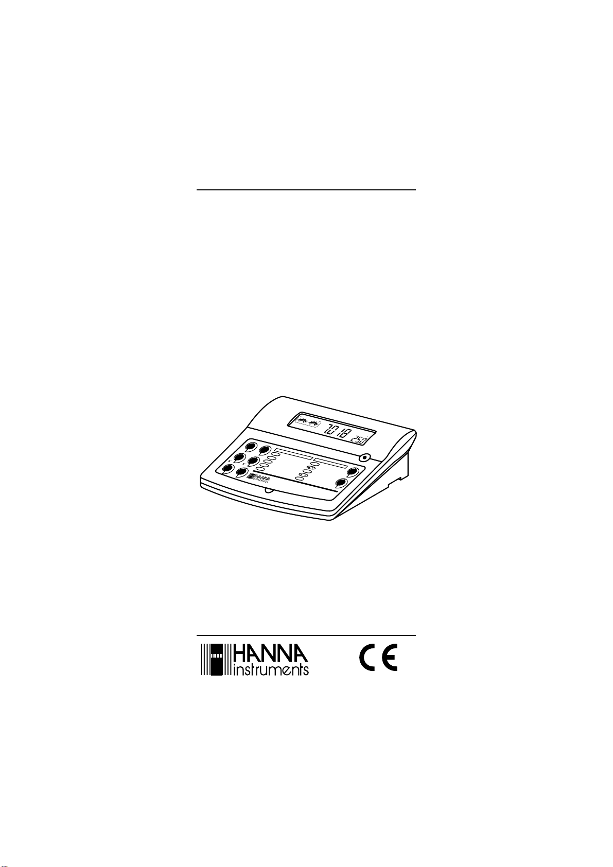
Instruction Manual
HI 221 HI 223
pH/mV/ºC
Bench Meters
with Calibration Check
POOR
GOOD
SLOW
FAST
CAL
C
C
LOG
RCL
GLP
CFM
CFM
RCL
SET/CLR
/GLP
ShowGLP Information
Functions
RANGE
SelectpH/ORP
LOG
StoreLog Information
RecallLog Information
SetInstrument Parameters
ClearLog/Cal Information
CFM
HI 223 Calibration Check
Microprocessor pH Meter
pH Calibration
CAL
StartCalibration
/
Select1
CFM
Confirm
1 Buffer
/
Select2
nd
Buffer
Confirm
nd
2
Buffer
pH
ATC
C
st
Buffer
st
RANGE
SET
CLR
Manufacturer since 1978
www.hannainst.com
1
Page 2

Dear Customer,
Thank you for choosing a Hanna Instruments product.
Please read this instruction manual carefully before using the instrument.
This manual will provide you with the necessary information for correct use of
the instrument, as well as a precise idea of its versatility.
If you need additional technical information, do not hesitate to e-mail us at
tech@hannainst.com or turn to the back cover for our worldwide contact list.
These instruments are in compliance with directives.
WARRANTY
HI 221 and HI 223 are guaranteed for two years against defects in workman-
ship and materials when used for their intended purpose and maintained
according to instructions. The electrodes and the probes are guaranteed for a
period of six months. This warranty is limited to repair or replacement free of
charge.
Damage due to accidents, misuse, tampering or lack of prescribed maintenance are not covered.
If service is required, contact the dealer from whom you purchased the
instrument. If under warranty, report the model number, date of purchase,
serial number and the nature of the problem. If the repair is not covered by
the warranty, you will be notified of the charges incurred. If the instrument is
to be returned to Hanna Instruments, first obtain a Returned Goods Authorization number from the Technical Service department and then send it with
shipping costs prepaid. When shipping any instrument, make sure it is
properly packaged for complete protection.
TABLE OF CONTENTS
WARRANTY ................................................................................................................... 2
PRELIMINARY EXAMINATION ........................................................................................... 3
GENERAL DESCRIPTION.................................................................................................... 3
FUNCTIONAL DESCRIPTION ............................................................................................. 4
HI 221 SPECIFICATIONS .................................................................................................. 5
HI 223 SPECIFICATIONS ................................................................................................... 6
OPERATIONAL GUIDE ....................................................................................................... 7
pH CALIBRATION ................................................................................................................ 9
ENHANCED CALIBRATION MESSAGES ....................................................................12
ELECTRODE CONDITION AND RESPONSE TIME ............................................................14
GOOD LABORATORY PRACTICE (GLP) .........................................................................15
LOGGING .........................................................................................................................18
SETUP ............................................................................................................................ 22
TEMPERATURE CALIBRATION (FOR TECHNICAL PERSONNEL ONLY) .............................. 25
mV CALIBRATION (FOR TECHNICAL PERSONNEL ONLY) .................................................. 27
PC INTERFACE ............................................................................................................... 28
pH VALUES AT DIFFERENT TEMPERATURES .................................................................... 30
ELECTRODE CONDITIONING & MAINTENANCE .............................................................. 31
TROUBLESHOOTING GUIDE .......................................................................................... 33
TEMPERATURE CORRELATION FOR pH SENSITIVE GLASS ............................................34
ACCESSORIES ................................................................................................................ 36
RECOMMENDATIONS FOR USERS ..................................................................................... 39
2
Page 3

PRELIMINARY EXAMINATION
Remove the instrument from the packing material and examine it carefully to
make sure that no damage has occurred during shipping. If there is any
damage, notify your Dealer or the nearest Hanna Customer Service Center.
Each instrument is supplied complete with:
HI 1131P Glass-body Combination pH Electrode with 1 m (3.3 ) cable
HI 7669/2W Temperature Probe
HI 76404 Electrode Holder
pH 4.01 & 7.01 Buffer Solutions (20 mL each)
HI 7071S Electrolyte Solution
12 VDC Power Adapter
Instruction Manual
Note: Save all packing material until you are sure that the instrument
functions correctly. All defective items must be returned in the original
packing with the supplied accessories.
GENERAL DESCRIPTION
HI 221 and HI 223 are logging microprocessor-based pH/ORP/temperature
bench meters with Calibration Check.
Calibration Check performs a set of diagnostic tests during calibration using the
history of electrode slope and offset to detect problems that can cause loss of
accuracy.
Calibration Check Features are:
Enhanced Calibration Messages
During calibration the user is warned if one or more parameters are not suitable
to perform an accurate calibration.
Electrode Condition on LCD Display
Determined from the electrode offset and slope.
Electrode response time on LCD Display
Determined from electrode performance during calibration.
Calibration Alarm Time Out
Can be programmed from 1 to 7 days or can be disabled.
Other features include:
One or two point calibration with seven memorized buffers (1.68, 4.01, 6.86,
7.01, 9.18, 10.01 and 12.45 pH), logging up to 100 samples (for HI 221)
and 500 samples (for HI 223), last calibration date and data (GLP), pH
reading with manual or automatic temperature compensation and PC software
interface.
3
Page 4
Front Panel
Rear Panel
Front Panel
Front Panel
1
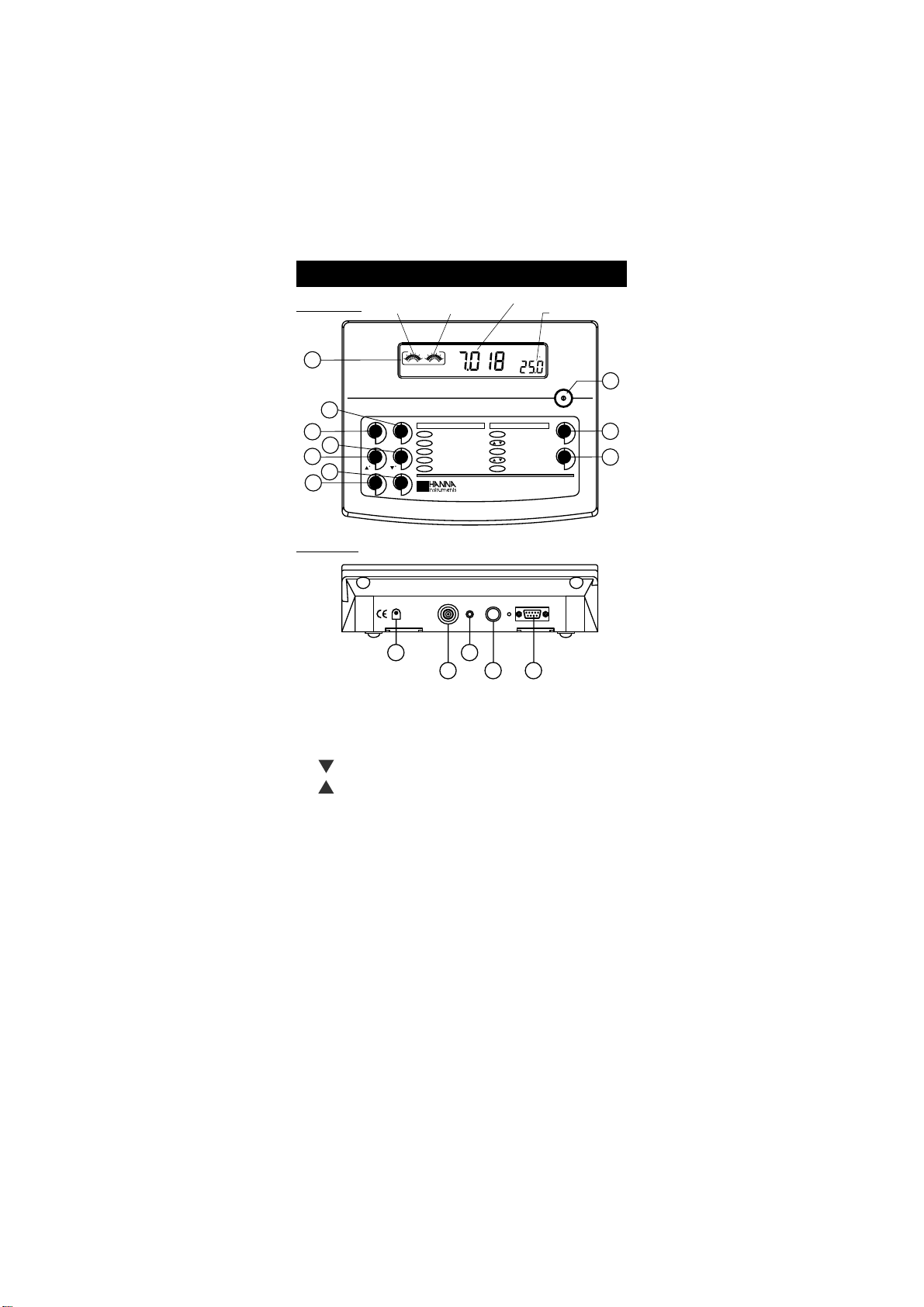
FUNCTIONAL DESCRIPTION
POOR GOOD
Electrode
Response
SLOW
FAST
Primary LCD
pH
Secondary LCD
ATC
C
Electrode
Condition
10
2
3
4
5
6
7
Rear Panel
Rear Panel
Functions pH Calibration
Select pH/ORP
CAL
LOG
GLP
RCL
POWER
12VDC
LOG
Store Log Information
RCL
Recall Log Information
Set Instrument Parameters
SET/CLR
Clear Log/Cal Information
CC
CFM/GLP
Show GLP Information
INPUT TEMP
RANGE
CFM
11
12
CAL
Start Calibration
st
/
Select 1 Buffer
st
CFM
Confirm 1 Buffer
nd
/
Select 2 Buffer
nd
CFM
Confirm 2 Buffer
HI 223 Calibration Check
Microprocessor pH Meter
RS232
13
14
15
RANGE
SET
CLR
8
9
1) Liquid Crystal Display (LCD).
2) CFM / GLP key, to confirm different values or to display Good Laboratory
Practice information.
3) CAL key, to enter and exit/escape the calibration mode.
4) / ºC key, to manually decrease temperature, or other parameters.
5) / ºC key, to manually increase temperature, or other parameters.
6) RCL key, to enter or exit the recall mode.
7) LOG key, to store measured data.
8) RANGE key, to select the measurement range or to switch the focused data.
9) SET / CLR key, to enter the Setup mode or clear calibration history.
10) ON / OFF switch.
11) Power supply socket.
12) BNC electrode connector.
13) Pin input socket.
14) Temperature probe socket.
15) RS232 serial communication connector.
Note: Pin input socket cannot be used as a reference input for electrodes with
separate reference.
4
Page 5
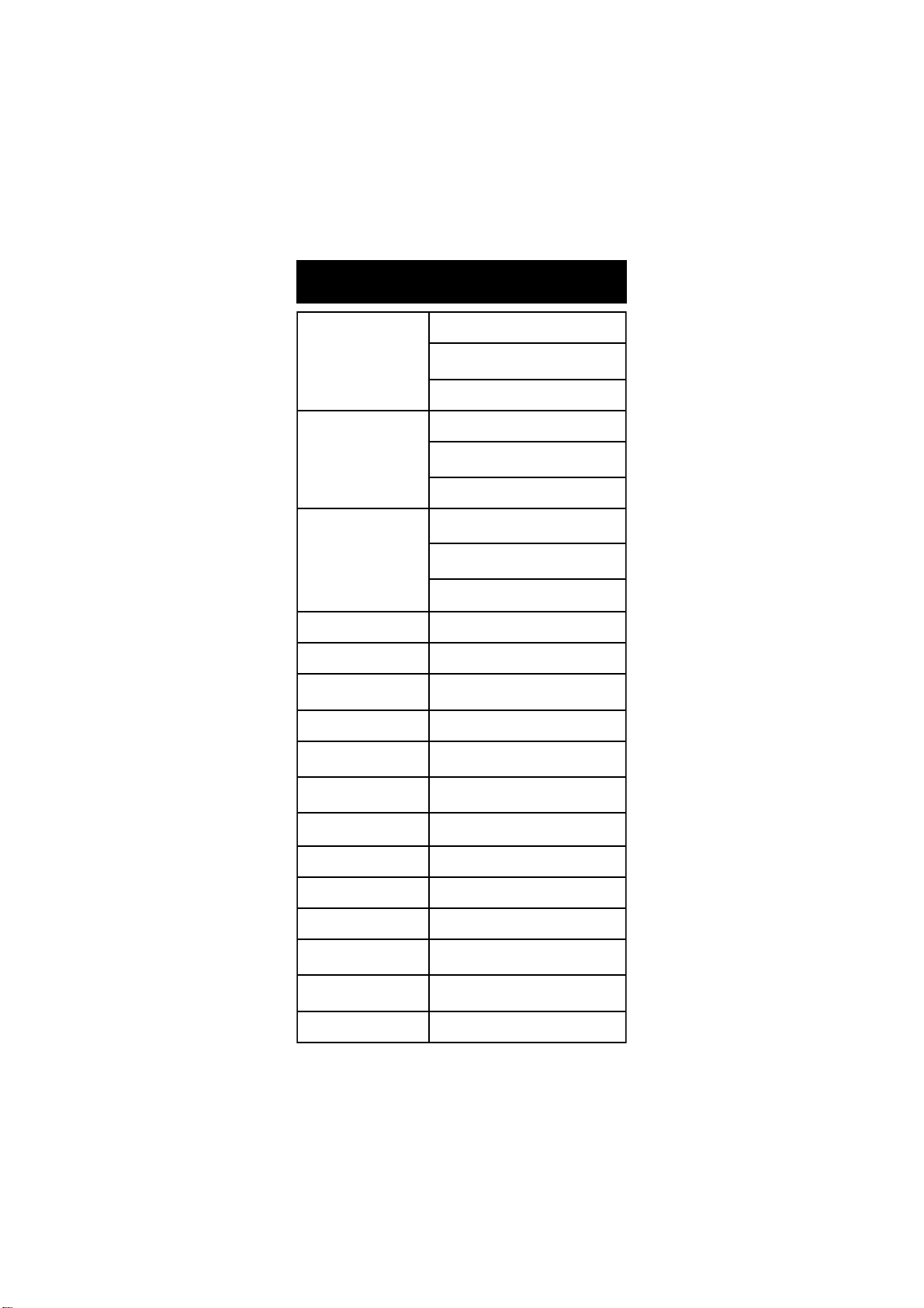
HI 221
SPECIFICATIONS
egnaR
noituloseR
ycaruccA
F°86/C°02@
kcehCnoitarbilaCseY
ecafretnIretupmoC232SRdetalosi-otpO
noitarbilaCHp
gniggoLstniop001
noitasnepmoCerutarepmeT
edortcelEHp
eborPerutarepmeT)dedulcni(eborpleetssselniatsW2/9667IH
Hp00.61ot00.2
Vm9.996±
Vm0002±
C°0.021ot0.02
Hp10.0
)Vm9.996±(Vm1.0
)Vm0002±(Vm1
C°1.0
Hp10.0±
)Vm9.996±(Vm2.0±
)Vm0002±(Vm1±
C°4.0±
elbaliavasreffub7,tniop2ro1
)54.21,10.01,81.9,10.7,68.6,10.4,86.1(
:morfcitamotuArolaunaM
C°021ot02
elballifernoitcnujelgnis,ydobssalgP1311IH
)dedulcni(nip+CNB,llec
ecnadepmItupnI01
ylppuSrewoP)dedulcni(retpadaCDV21
snoisnemiD47x281x042mm)"9.2x1.7x4.9(
thgieW
tnemnorivnE
ytnarraW2sraey
5
21
9
)bl5.2(gk1.1
)bl5.5(gk5.2redlohhtiwtik
)F°221-23(C°05-0
gnisnednocnon%59HRxam
Page 6
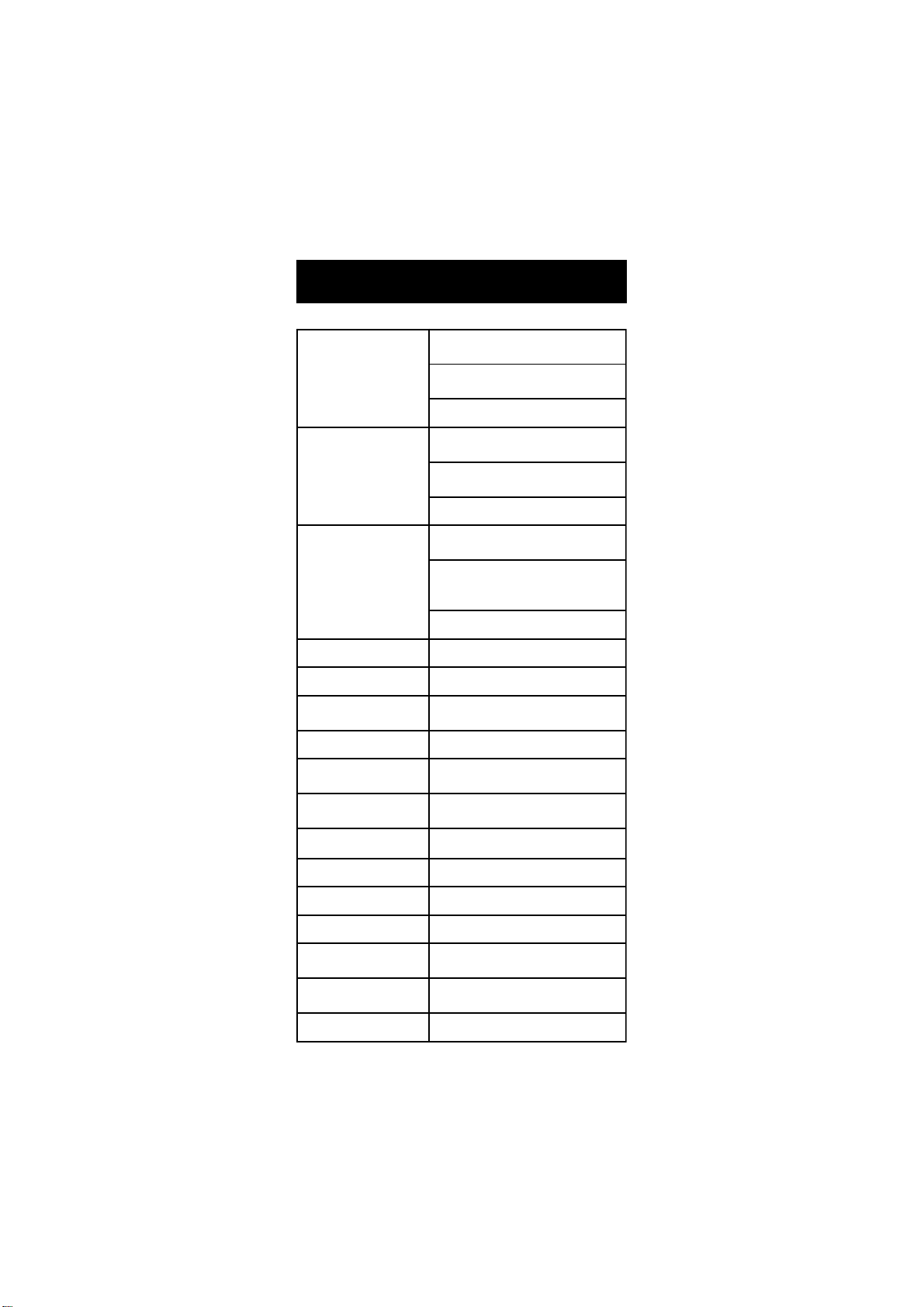
HI 223
SPECIFICATIONS
egnaR
noituloseR
ycaruccA
F°86/C°02@
kcehCnoitarbilaCseY
ecafretnIretupmoC232SRdetalosI-otpO
noitarbilaCHp
gniggoLstniop005
noitasnepmoCerutarepmeT
edortcelEHp
eborPerutarepmeT)dedulcni(eborpleetssselniatsW2/9667IH
ecnadepmItupnI01
1.0Vm9.999±()Vm
1Vm0002±()Vm
1±Vm0002±()Vm
00.61ot00.2Hp
000.61ot000.2Hp
9.999±Vm
0002±Vm
°0.021ot0.02C
10.0Hp
100.0Hp
°1.0C
10.0±Hp
200.0±Hp
2.0±Vm9.996±(m)V
5.0±Vm9.999±()Vm
°4.0±C
°021ot02C
21
9
elbaliavasreffub7,tniop2ro1
)54.21,10.01,81.9,10.7,68.6,10.4,86.1(
:morfcitamotuArolaunaM
elballifernoitcnujelgnis,ydobssalgP1311IH
)dedulcni(nip+CNB,llec
ylppuSrewoPretpadaCDV21
snoisnemiD47x281x042mm)"9.2x1.7x4.9(
thgieW
tnemnorivnE
ytnarraWsraey2
6
°05-0C °221-23(F)
)bl5.2(gk1.1
)bl5.5(gk5.2redlohhtiwtik
gnisnednocnon%59HRxam
Page 7
OPERATIONAL GUIDE
POWER CONNECTION
Plug the 12 VDC adapter into the power supply socket.
Note: These instruments use non volatile memory to retain the pH, mV,
temperature calibrations and all other settings, even when unplugged.
Note: Make sure a fuse protects the mains line.
ELECTRODE AND PROBE CONNECTIONS
For HANNA P Type pH or ORP electrodes (with internal reference) connect the
electrodes BNC to the socket on the back of the instrument and the pin to the
appropriate socket.
Note: Electrode condition and response information is displayed on the bar
graph gauges during the day the calibration is performed, only if
HANNA P type (PIN) electrodes are used.
If the electrode is not recognized as a HANNA P type electrode, the bar
graph gauges will blink (25 seconds OFF, 4 seconds ON, full bar graph).
For temperature measurement and automatic temperature compensation
connect the temperature probe to the appropriate socket.
INSTRUMENT START-UP
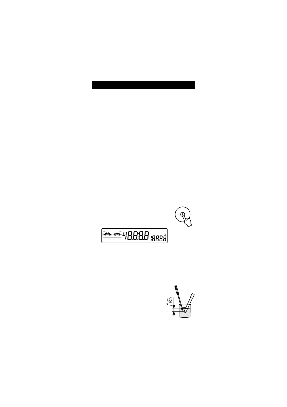
Turn the instrument on by pressing the ON/OFF switch.
All LCD tags are displayed and a beep is sounded
while the instrument performs a self test.
CFM
CAL
DUE
POOR GOOD
CHECK
WRONG
CONTAMINATED
ELECTRODE
CLEAN
SLOW
BUFFER
BUFFER
Unscrew electrode refilling cap
FAST
CLEAR CAL if new electrode
pH
mV
SETUP
LOG
BUFFER 12
ATC
MTC
RCL
DEL
The Unscrew electrode refilling cap message reminds the user to loosen
or remove the electrode refilling cap to improve the electrodes response
time.
The instrument automatically defaults to pH measurement mode unless a
HANNA P type ORP electrode is detected.
pH MEASUREMENT
Make sure the instrument has been calibrated before
taking pH measurements.
Submerge the tip (4 cm/1½) of a properly condi-
tioned electrode (see page 31) and the temperature probe into the sample to be tested. Allow time
for the electrode to stabilize.
7
Page 8
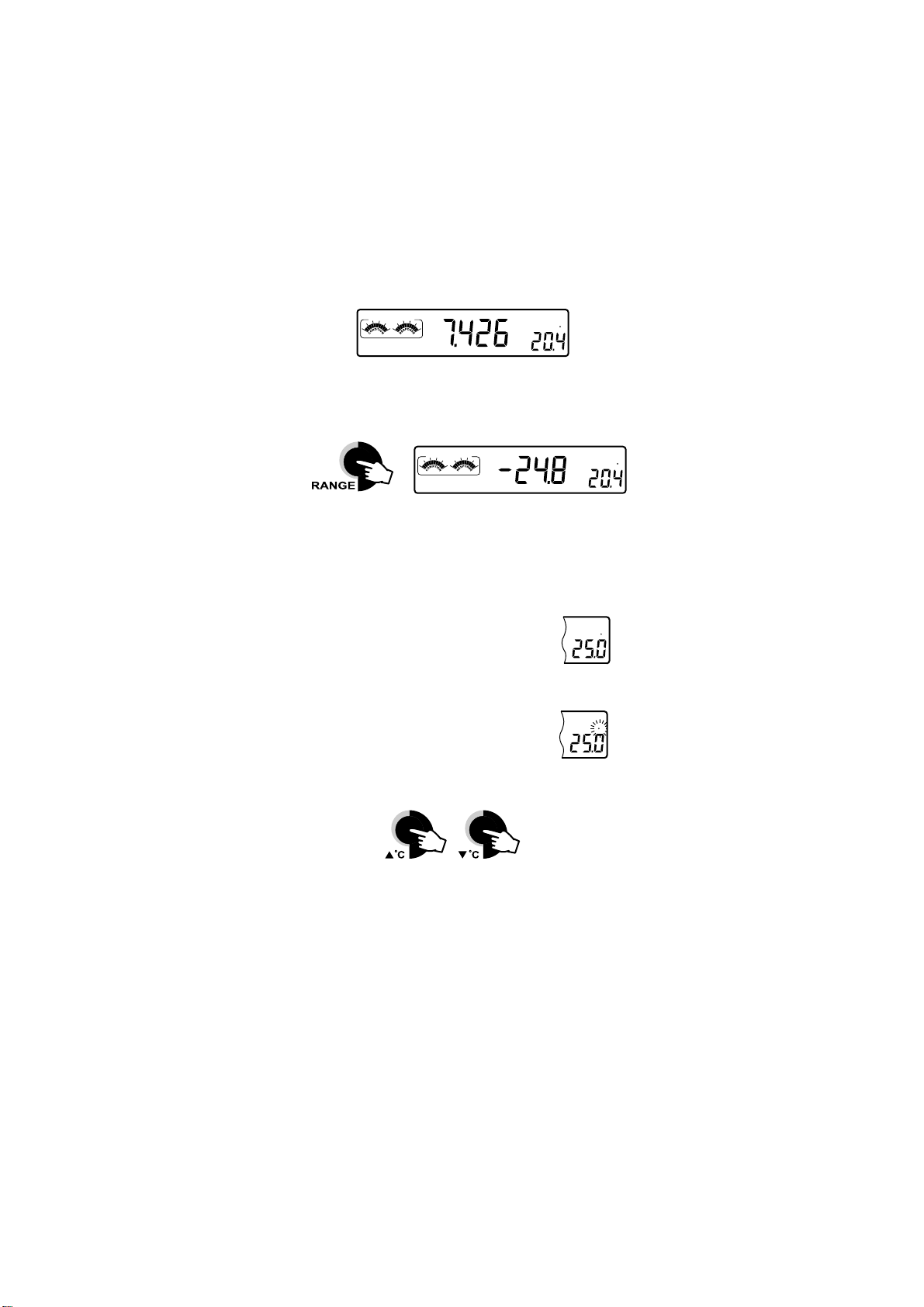
The pH is displayed on the primary LCD and the temperature on the
secondary LCD.
ATC
POOR GOOD
SLOW
FAST
pH
C
The pH reading is out of range, the closest full-scale value will be displayed
blinking on the primary LCD.
It is also possible to view the mV reading by pressing the RANGE key.
POOR GOOD
SLOW
FAST
mV
If measurements are taken successively in different samples, it is recommended
to rinse the electrode thoroughly with deionized water or tap water and then
with some of the next sample to prevent cross-contamination.
The pH reading is affected by temperature. In order to measure the pH
accurately, this temperature effect must be compensated for. To use the
Automatic Temperature Compensation feature, connect
and submerge the HI 7669/2W temperature probe into
ATC
C
the sample as close to the electrode as possible and wait
for a few minutes.
If the temperature of the sample is known, manual compensation can be
performed by disconnecting the temperature probe.
The display will then show the default temperature of 25 °C
MTC
C
or the last recorded temperature reading with the °C
symbol blinking.
The temperature can now be adjusted with the ARROW keys (from -20.0 ºC
to 120.0 ºC).
ORP MEASUREMENTS
An optional ORP electrode must be used to perform ORP measurements (see
Accessories).
Oxidation-Reduction Potential (REDOX) measurements provide the quantification of the oxidizing or reducing power of the tested sample.
To correctly perform a REDOX measurement, the surface of the ORP electrode
must be clean and smooth.
Pretreatment solutions are avaible to condition the electrode and speed up the
response time.
8
C
Page 9
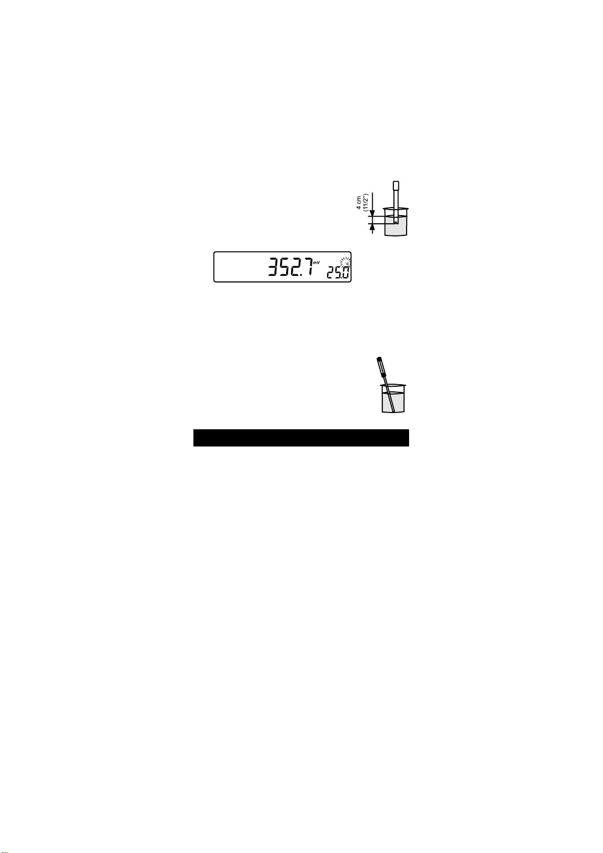
The instrument automatically defaults to the ORP
measurement mode if HANNA P type ORP electrode
is detected.
Submerge the ORP electrode tip (4 cm/1½) into the
sample. Allow a few minutes for the reading to stabilize.
The instrument displays the mV reading on the primary LCD.
If the reading is out of range, the closest full-scale value will be displayed
blinking on the primary LCD.
TAKING TEMPERATURE MEASUREMENTS
Connect the HI 7669/2W temperature probe and turn the
instrument on. Dip the temperatureprobeinto the sample and
allow the reading on the secondary LCD to stabilize.
pH CALIBRATION
Calibrate the instrument frequently, especially if high accuracy is required. For
best results and constant display of electrode condition and electrode response
on the bar graph gauges we suggest at least a daily calibration.
The instrument should be re-calibrated:
Whenever the pH electrode is replaced.
At least once a day.
After testing aggressive chemicals.
If high accuracy is required.
If CAL DUE message is displayed during measurement.
Every time you calibrate the instrument use fresh buffers and perform an
electrode cleaning procedure (see page 32).
PREPARATION
Pour small quantities of the buffer solutions into clean beakers. If possible, use
plastic or glass beakers to minimize any EMC interferences.
For accurate calibration and to minimize cross-contamination, use two beakers
for each buffer solution. One for rinsing the electrode and one for calibration.
9
Page 10
PROCEDURE
The user has a choice of 7 memorized buffers: pH 1.68, 4.01, 6.86, 7.01,
9.18, 10.01 and 12.45.
It is always recommended to perform a two-point calibration, however the
instrument also allows a one-point calibration, as described on page 11.
TWO-POINT CALIBRATION
For most applications it is recommended that pH 7.01 or 6.86 buffers be used
as the first calibration point and pH 4.01 (for acidic samples) or pH 9.18/
10.01 (for alkaline samples) as the second calibration point.
Note: The pH 12.45 buffer is not for general measurement; use only if the
sample is very alkaline to avoid sodium error.
Immerse the pH electrode and the temperature probe approximately
4 cm (1½) into the buffer solution of your choice (pH 1.68, 4.01,
6.86, 7.01, 9.18, 10.01 or 12.45) and stir gently. The temperature
probe should be close to the pH electrode.
Press the CAL key. CAL and pH tags will be on, and the CLEAR
CAL if new electrode tag will blink.
CAL
CLEAR CAL if new electrode
pH
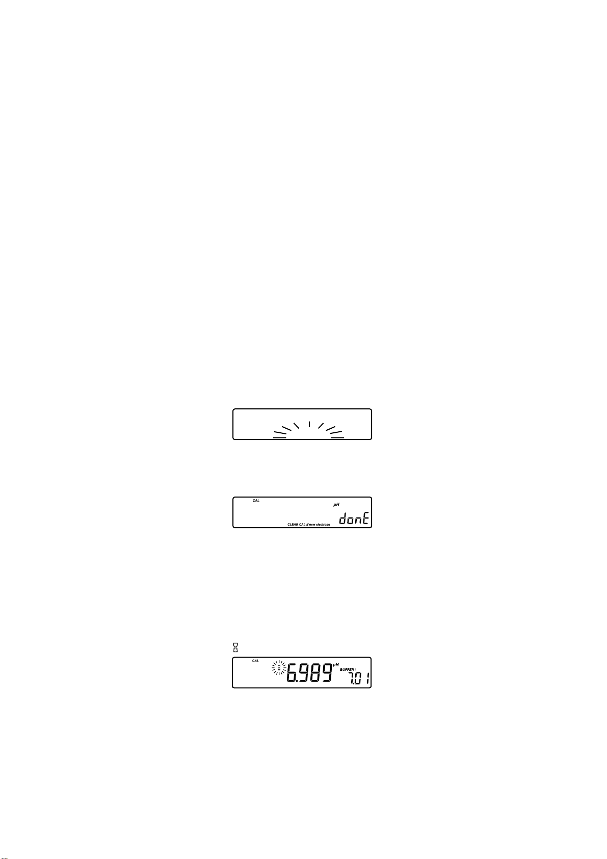
Press the CLR key if you are using a new electrode or want to clear the
calibration history. The instrument will display the donE message for
a few seconds.
It is very important to clear the calibration history when a new electrode is
used because all error and warning messages that appear during calibration
depend on the calibration history.
Press the CAL key, or wait a few seconds to continue.
Note: The above behavior happens only if calibration history is not empty.
The instrument will display the measured pH on the primary LCD, and
the most common buffer (7.01) on the secondary LCD along with
CAL, pH and BUFFER 1 tags.
The tag will blink until the reading has stabilized.
ATC
10
Page 11
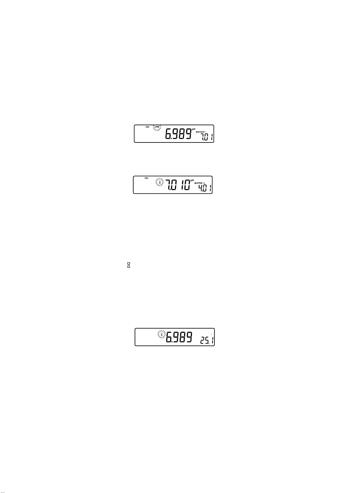
Press the ARROW keys to select a different buffer value, if necessary.
When the reading is stable and close to the selected buffer, the CFM
tag will blink and if enabled, an audible signal will sound.
ATC
Press the CFM key to confirm the calibration. The instrument will ask for a
second calibration buffer and display the measured pH on the first LCD line
and the second calibration buffer on the second LCD line.
ATC
If necessary, press the ARROW keys to select a different buffer value.
Note: The instrument will automatically skip the buffer used for the first point.
It also skips 6.86 if 7.01 was used, and vice versa. Likewise, it will skip
9.18 if 10.01 has been used, and vice versa.
Rinse the electrode in one of the beakers of the second buffer solution, then
immerse the pH electrode and the temperature probe approximately 4 cm
(1½) into the second buffer solution and stir gently. The temperature
probe should be close to the pH electrode.
The indication will blink on LCD until the reading has stabilized.
When the reading is stable and close to the selected buffer, the
CFM tag will blink.
Press the CFM key to confirm the calibration.
The instrument will return to normal operation and will memorize the calibra-
tion data.
Note: Press the RANGE key any time during calibration to display the
temperature reading.
CAL
ATC
pH
C
ONE-POINT CALIBRATION
Proceed as described in two-point calibration.
Press the CAL key after the first calibration point has been confirmed.
The instrument will return to normal operation and will memorize the one-
point calibration data.
11
Page 12
ENHANCED CALIBRATION MESSAGES
The stored calibration history to used issue error and warning messages during
calibration to help ensure the highest accuracy.
As electrode aging is normally a slow process, substantial changes from
previous calibrations are likely due to a temporary problem with the electrode
or buffers. Calibrating under these conditions will give measurement errors.
ERROR MESSAGES
Error messages appear if one or all of the calibration parameters are out of
accepted windows. When these messages are displayed calibration cannot be
confirmed.
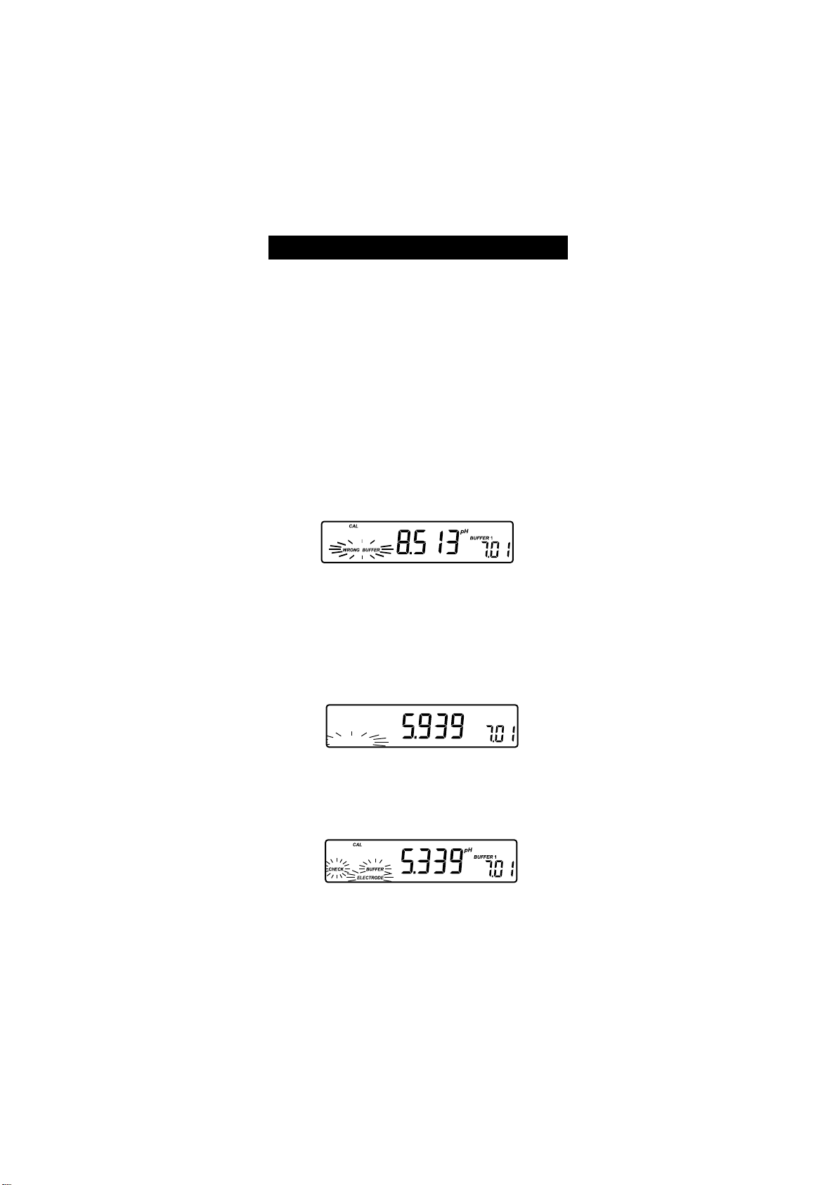
WRONG BUFFER
This message appears when the difference between the pH reading and the
value of the selected buffer is too big. If this error message is displayed, check
if you have selected the proper calibration buffer.
ATC
CLEAN ELECTRODE
This error message indicates a bad electrode condition (offset out of accepted
window, or slope under the accepted lower limit).
Clean the electrode according to the Cleaning Procedure on page 32 to
improve its condition and repeat the calibration. This ensures the removal of
film, dirt or deposits on the glass bulb and reference junction.
CAL
ELECTRODECLEAN
pH
ATC
BUFFER 1
CHECK ELECTRODE alternating with CHECK BUFFER
This error message appears when electrode slope exceeds the highest accepted
slope limit. You should check your electrode and use fresh buffer.
ATC
12
Page 13

ELECTRODE
This message appears if the cleaning procedure performed as a result of the
above two messages is found by the instrument to be unsuccessful. Replace the
electrode.
ATC
WRONG BUFFER TEMPERATURE
This message appears if the temperature of the buffer is outside the defined
buffer temperature range.
CAL
WRONG
BUFFER
CLEAR CAL if new electrode
ATC
pH
WARNING MESSAGES
During calibration, the Calibration Check feature analyzes the electrode calibration
history and warns the user when problems have been detected. It is possible to
over ride the warning messages and confirm the calibration but it is not
recommended.
CLEAR CAL IF NEW ELECTRODE
This warning is displayed any time the new calibration parameters are better
than the previous parameters. You can clear the calibration history by pressing the CLR key, or continue by pressing the CAL key.
CAL
CLEAR CAL if new electrode
pH
ATC
BUFFER 1
CLEAN ELECTRODE
This warning appears during Calibration Check for the second calibration
buffer when the instrument has detected a small variation of offset or both
offset and slope parameters. This variation may result from dirt on the
electrode. Refer to the electrode cleaning procedure. This ensures the removal
of film, dirt or deposits on the glass bulb and reference junction.
CFM
CAL
ELECTRODECLEAN
pH
ATC
BUFFER 1
CLEAN ELECTRODE alternating with CHECK BUFFER
This warning appears during Calibration Check in the first calibration buffer as
13
Page 14

a result of unacceptable offset variation or in the second calibration buffer as
a result of unacceptable slope variation. This variation may result from dirt on
the electrode or contaminated buffer. Refer to the electrode cleaning procedure
or use fresh buffer.
CAL
CHECK
CFM
BUFFER
ELECTRODECLEAN
pH
ATC
BUFFER 1
CONTAMINATED BUFFER
This warning message appears in order to alert that the buffer could be
contaminated. Refresh your buffer and continue the calibration procedure.
ATC
ELECTRODE CONDITION &
ELECTRODE RESPONSE TIME
When using an appropriate HANNA P Type BNC electrode with pin, HI 221
and HI 223 will assess electrode condition and response time during each
calibration, and display the calibration status for the rest of the day.
POOR GOOD
SLOW
FAST
The digital gauge for electrode condition is a representation of the offset and
slope performance of the electrode. The response gauge is a function of the
stabilization time between the first and second calibration buffers. These
gauges reflect electrode performance and should be expected to slowly decrease over the life of the electrode.
The condition and response gauges show the electrodes condition at the time
of calibration only and are displayed for the rest of the day the calibration is
performed. For a continuous display of electrode condition at the time of
calibration, daily calibration is necessary. The condition and response are also
visible when viewing GLP data.
If the instrument is not calibrated or it has been calibrated only at one point
or if the calibration history was deleted, the electrode condition and the
electrode response gauges will be empty.
14
SLOW
FAST
POOR GOOD
Page 15

Also, when the instrument cannot evaluate the electrode response or pH 1.68 or
pH 12.45 buffer were used as calibration buffer, the response gauge will be empty.
If the electrode is in a very poor condition the first condition segment will blink.
If electrode response is very slow the first response segment will blink.
GOOD LABORATORY PRACTICE (GLP)
GLP is a set of functions that allows the storage and retrieval of data regarding
the maintenance and status of the electrode.
All data regarding the last calibration (one or two points) is stored for the user
to review when necessary. This data includes the following: calibration time
stamp, offset (in mV), slope (in mV/pH), electrode condition and response
gauges, calibration buffers and the amount of time until a new calibration is
required.
CALIBRATION ALARM TIME-OUT
HI 221 and HI 223 allow the user to set the number of days before the next
required pH calibration. This value can be set from 1 to 7 days. The default
value is OFF (disabled).
The instrument checks if the time-out time has expired. If the time has
elapsed, the CAL DUE will blink as a reminder.
Note: If the instrument was not calibrated, or if the calibration history was
deleted, the CAL DUE message will be displayed even if this feature is
disabled in the SETUP menu.
If the instrument was calibrated using an electrode with pin and the
electrode is changed with an electrode without pin or vice-versa CAL
DUE will blink. This feature helps ensure use of a calibrated instrument.
LAST CALIBRATION DATA
Last calibration data is stored automatically after a successful calibration.
To view the pH calibration data, press the GLP key when the instrument is in
pH measuring mode.
The instrument will display the time of the last calibration.
Press the ARROW keys to view the following logged calibration parameters
(pressing the / ºC key):
_ The time (hh:mm).
15
Page 16

_ The date (mm.dd).
_ The year (yyyy).
_ The pH calibration offset.
_ The pH calibration slope in mV/pH normalized to 25 °C.
Note: If you calibrate using electrodes with pin the electrode condition and re-
sponse gauges appear while the offset and slope are displayed.
_ The first pH calibration buffer along with any warning messages issued
while calibrating at this point.
_ The second pH calibration buffer along with any warning messages issued
while calibrating at this point.
Note: If the last calibration was a single point calibration, the message for
the second buffer will be: no bUFF.
16
Page 17

_ The selected resolution of the instrument during calibration (HI 223 only).
CAL
RCL
pH
_ The calibration Alarm Time-Out status:
if disabled
or the number of days until the calibration alarm will be displayed
or if expired (7 days ago)
Press the GLP key at any time and the instrument will return to measuring mode.
If calibration has not been performed, the instrument displays no CAL
blinking.
17
Page 18

LOGGING
Up to 100 (HI 221) or 500 (HI 223) LOG samples can be stored in memory.
LOGGING THE CURRENT DATA
To store the current reading into memory press the LOG key while in measuring mode.
The instrument will display the current date (mm.dd) on the primary LCD, the
record number on the secondary LCD and the LOG tag will blink for a few
seconds (see example below: record No. 27 dated July 14):
If there are less than 5 memory locations remaining, the record number and
the Lo message will blink to alert the user.
If the log space is full, the FULL LOC message will be displayed and no more
data will be saved.
When the LOG key is pressed, a complete set of information is stored. The
parameters of a record are date, time, pH, mV, temperature, and pH
calibration data. If a HANNA P Type ORP electrode is used pH information is
not stored.
VIEW LOGGED DATA
Press the RCLkey to retrieve the information stored while in measuring mode.
If no data were logged the instrument displays:
18
Page 19

Otherwise the instrument will display log data on the primary LCD and the
last stored record number on the secondary LCD, along with the LOG and
the RCL tags.
Note: The LOG and RCL tags remain on LCD while instrument is in the
viewing logged data mode.
Press the RCL key at any time to return to measuring mode.
Press the ARROW keys to scroll between same parameter for different records,
while pH, mV, temperature, Hour, Year, oFFS, SLoP or dEL record
is displayed:
or to scroll between different dates while dAtE or dEL date is displayed.
LOG
RCL
Press the RANGE key and the instrument will display the next logged
parameter, as follows:
The mV value on the primary LCD and the record number on the secondary
LCD.
The temperature value on the primary LCD and the record number on the
secondary LCD.
The time on the primary LCD and the Hour message on the secondary
LCD.
19
Page 20

The date on the primary LCD and the dAtE message on the secondary
LCD.
The year on the primary LCD and the YEAr message on the secondary
LCD.
The calibration offset on the primary LCD and the oFFS message on the
secondary LCD.
The calibration slope on the primary LCD and the SLoP message on the
secondary LCD.
Note: Before displaying the Hour, Year, oFFS or SLoP messages, the
record number is displayed for about one second.
The RANGE key has no effect if nuLL record message is displayed on
the first LCD line.
LOG
RCL
or if nuLL date message is displayed.
LOG
RCL
You can skip this message by selecting an undeleted record (date)
using the ARROW keys.
20
Page 21

The dEL message on the primary LCD and the selected record or date on
the secondary LCD. The CFM and the DEL tags will blink:
Press SET key to select the current record, the records from the selected date or
all records to be deleted.
the date.
or ALL records.
Press the ARROW keys to change the record or the date.
Press the CFM key to confirm the deleting of the selected record, all the records
for the selected date, or all the records and the instrument will display on the
secondary LCD the nuLL message.
LOG
RCL
Note: Pressing RANGE key the instrument skips to the pH information on
the next undeleted record.
The instrument optimizes the usage of the memory when it returns to
measurement mode after a deleting operation is performed. This will
change the record numbers of logged data.
If all the records are deleted the instrument returns to the measuring
mode.
After the LOG key is pressed or dEL is confirmed the instrument will
display the amount of free log space for about one second (example:
25 records free).
LOG
21
Page 22

SETUP
Setup mode allows viewing and modification of the following parameters:
Calibration Alarm Time Out
Instrument ID
Current Time (hour & minute)
Current Date (month & day)
Current Year
pH Resolution (HI 223 only)
Beep Status
Baud Rate (serial communication)
Command Prefix (serial communication)
To enter the Setup mode press the SET/CLR key while the instrument is in
measuring mode. Press SET/CLR key to exit SETUP mode.
Select a parameter with the ARROW keys.
Press the CAL key to change a parameter value. The selected parameter will
start to blink.
Press the RANGE key to toggle between the displayed parameters.
Press the ARROWkeys to increase or decrease the displayed value.
Press the CFM key to save the modified value or the CAL key to cancel.
Press the ARROW keys to select the next/previous parameter.
CALIBRATION ALARM TIME OUT CHANGE
Press the CAL key when the calibration time out is displayed. Calibration time
out (OFF=disabled or 1 to 7 days) will begin blinking.
Press the ARROW keys to change the calibration time out value.
Press the CFM key to save the modified calibration time out value or press the
CAL key to cancel without saving the calibration time out.
INSTRUMENT ID PARAMETER CHANGE
Press the CAL key when the instrument ID is displayed. The instrument ID
(0000 to 9999) will begin blinking.
22
Page 23

Press the ARROWkeys to change the instrument ID value.
Press the CFM key to save the modified instrument ID value or press the CAL
key to cancel without saving the instrument ID.
Note: The instrument ID is downloaded to a PC as part of a logged data set
to identify its origin.
CURRENT TIME SET
Press the CAL key when the current time is displayed. The hour will begin
blinking.
Press the ARROWkeys to change the hour.
Press the RANGE key. The minutes will begin blinking.
Press the ARROW keys to change the displayed value.
Press the CFM key to save the modified value or press the CAL key
to cancel without saving the time.
CURRENT DATE SET
Press the CAL key when the current date is displayed. The month will begin
blinking.
Press the ARROWkeys to change the month.
Press the RANGE key. The day will begin blinking.
Press the ARROW keys to change the displayed value.
Press the CFM key to save the modified value or press the CAL key to cancel
without saving the date.
23
Page 24

CURRENT YEAR SET
Press the CAL key when the current year is displayed. The year will begin
blinking.
Press the ARROWkeys to change the year.
Press the CFM key to save the modified value or press the CAL key to cancel
without saving the year.
pH RESOLUTION SET (HI 223 ONLY)
Press the CAL key when the pH resolution is displayed. The pH resolution
(0.001 or 0.01) will begin blinking.
Press the ARROW keys to change the pH resolution.
Press the CFM key to save the modified pH resolution or press the CAL key to
escape without saving the pH resolution.
BEEP STATUS SET
Press the CAL key when the beep status is displayed. The beep status (On or
OFF) will begin to blink.
Press the ARROWkeys to change the beep status (On or OFF).
Press the CFM key to save the modified beep status or press the CAL key to
cancel without saving the beep status.
Note: If enabled, an audible signal will follow each key press. Inactive keys
have a longer beep. A longer beep is also sounded when the limits of
the range of a parameter are reached.
An audible signal will also sound when the reading becomes stable
during calibration.
24
Page 25

SERIAL COMMUNICATION BAUD RATE SET
Press the CAL key when the baud rate is displayed. The baud rate (600,
1200, 2400, 4800 or 9600) will begin to blink.
Press the ARROWkeys to change the baud rate.
Press the CFM key to save the modified baud rate or press the CAL key to
cancel without saving the baud rate.
SERIAL COMMUNICATION COMMAND PREFIX SET
Press the CAL key when the command prefix is displayed. The command prefix
(0 to 47) will begin to blink.
Press the ARROW keys to change the command prefix.
Press the CFM key to save the modified command prefix value or press the CAL
key to cancel without saving the command prefix.
Note: See the PC Interface section on page 28 for a complete explanation. The
command prefix must be 16 if the HI 92000 PC software is used.
TEMPERATURE CALIBRATION
(FOR TECHNICAL PERSONNEL ONLY)
The instruments are factory calibrated for temperature.
Hannas temperature probes are interchangeable and temperature calibra-
tion is not necessary when replaced.
If the temperature measurements are not accurate, temperature recalibration
should be performed.
For an accurate recalibration, contact your dealer or the nearest Hanna
Customer Service Center, or follow the instructions below.
Switch off the instrument.
Prepare a vessel containing ice and water and another one containing hot
water (around 50 °C). Place insulation material around the vessels to
minimize temperature changes during calibration.
Use a ChecktempC or a calibrated thermometer with a resolution of 0.1 °C
as a reference thermometer.
Immerse the temperature probe and the ChecktempC into the vessel
25
Page 26

containing ice and water. Wait a few minutes for the probe to stabilize.
Press the CAL and LOG keys simultaneously and then switch the instru-
ment on. After a few seconds, the instrument enters the temperature
calibration mode. The CAL tag will come on. The primary LCD will
display the measured temperature or the - - - - message if the
measured temperature is out of range. The secondary LCD will display 0.0 °C
(First calibration point). The tag will blink until the reading has
stabilized.
Use the ARROW keys to set the reading on the secondary LCD to that of
ice and water measured by ChecktempC (for example, -0.1 °C).
CAL
C
-0.1°C
When the reading is stable and close to the selected calibration point, the
CFM tag will blink.
Press the CFM key to confirm the calibration or the CAL key to leave the
calibration mode.
The secondary LCD will display 50.0 °C (Second calibration point).
Immerse the temperature probe and the ChecktempC into the second
vessel.
Allow a few minutes for the probe to stabilize.
The tag will blink until the reading has stabilized.
Use the ARROW keys to set the reading on the secondary LCD to that of
the hot water bath.
When the reading is stable and close to the selected calibration point, the
CFM tag will blink.
CFM
CAL
C
Press the CFM key to confirm the calibration or the CAL key to leave the
calibration mode.
Note: If the measured value is not close enough to the displayed value on
secondary LCD, the WRONG tag will blink. In this case, check if the
value set on secondary LCD and the temperature measured with
ChecktempC are close. Change the temperature probe and restart
calibration if necessary.
26
Page 27

mV CALIBRATION
(FOR TECHNICAL PERSONNEL ONLY)
All instruments are factory calibrated for mV.
Hannas pH and ORP electrodes are interchangeable and mV calibration is
not needed when replaced.
If the mV measurements are not accurate, mV recalibration should be carried
out.
For an accurate recalibration, contact your dealer or the nearest Hanna
Customer Service Center or follow the instructions below.
A two or three point calibration can be performed at 0 mV, +600 mV and
+1800 mV.
Switch off the instrument.
Attach a mV simulator with an accuracy of at least ±0.1 mV to the BNC
connector.
Press the RCL and CFM/GLP keys simultaneously and switch the instru-
ment on. After a few seconds, the instrument enters the mV calibration
mode.
The primary LCD will show the CAL and mV tags along with mea-
sured mV and the secondary LCD will display 0.0 calibration point.
Set 0.0 mV on the simulator.
The tag will blink on LCD until the reading has stabilized.
When the reading is stable, the CFM tag will blink.
Press the CFM key to confirm the calibration.
The instrument will prompt for a second calibration point and will display
600 on the secondary LCD line.
Set the simulator to +600.0 mV.
The tag will blink on the LCD until the reading has stabilized.
When the reading is stable, the CFM tag will start to blink.
Press the CFM key to confirm the calibration.
The instrument will prompt for a third calibration point and will display
1800 on the secondary LCD line.
The two-point mV calibration is now complete.
Set +1800.0 mV on the simulator.
The tag will blink on the LCD until the reading has stabilized.
When the reading is stable, the CFM tag will start to blink.
Press the CFM key to confirm the calibration.
The instrument will memorize the calibration and return to measuring
mode.
27
Page 28

Note: Press the CAL key to leave the calibration mode at any time.
If the measured value is not close to the calibration point, the WRONG
tag will start to blink. In this case, check if the value set on the
simulator is the same as the calibration value on the instrument. Set
the proper value on the simulator.
PC INTERFACE
Data transmission from the instrument to the PC can be done with the HI
92000 Windows® compatible software (optional). The HI 92000 also offers
graphing and on-line help.
Data can also be exported to the most popular spreadsheet programs for
further analysis.
To connect your instrument to a PC, use the optional Hanna HI 920010 cable.
Make sure that your instrument is switched off and plug one end into the
instruments RS232C socket and the other end into the serial port of your PC.
Note: Cables other than HI 920010 may use a different configuration, in
which case communication between the instrument and the PC may
not be possible.
If you are not using optional Hanna HI 92000 software, please see the
following instructions.
The Command Prefix must be 16 when using HI 92000 software.
SENDING COMMANDS FROM PC
It is also possible to remotely control the instrument with any terminal program. Use the optional Hanna HI 920010 cable to connect the instrument to
a PC, start the terminal program and set the communication options as
follows: 8, N, 1, no flow control.
COMMAND TYPES
To send a command to the pH meter the scheme is:
<command prefix> <command> <CR>
where: <command prefix> is a selectable ASCII character
between 0 and 47 (default 16).
<command> is the command code (3 characters).
Note: Either small or capital letters can be used.
28
Page 29

SIMPLE COMMANDS
RNG Is equivalent to pressing the RANGE key
CAL Is equivalent to pressing the CAL key
CFM Is equivalent to pressing the CFM/GLP key
UPC Is equivalent to pressing the UP arrow key
DWC Is equivalent to pressing the DOWN arrow key
SET Is equivalent to pressing the SET/CLR key
COMMANDS REQUIRING AN ANSWER
pH? Causes the instrument to send the pH reading (Err 1 is sent if
out of range). If the range is set to mV, Err 6 is received.
MV? Causes the instrument to send the mV reading (Err 2 is sent if
out of range). If the range is set to pH, Err 6 is received.
TM? Causes the instrument to send the temperature reading
(Err 3 is sent if out of range).
MDR Requests the instrument model name and firmware code.
PAR Requests the setup parameters (instrument ID, calibration alarm
time-out, pH range, beep status).
NSL Requests the number of logged samples.
GLP Requests the calibration data record.
LOD xxx Requests the xxxth record logged data.
LOD ALL Requests all logged data.
Invalid commands will be ignored. The characters sent by the instrumentare
always capital letters. When the instrument receives an unknown or a corrupted command, it will send a character CAN (ASCII Code 24).
29
Page 30

pH VALUES AT DIFFERENT
TEMPERATURES
Temperature has an effect on pH. The calibration buffer solutions are affected
by temperature changes to a lesser degree than normal solutions. During
calibration the instrument will automatically calibrate to the pH value corresponding to the measured or set temperature.
PMETSEULAVHp
CºFº86.110.468.610.781.910.0154.21
023 76.110.489.631.764.923.0124.31
514 76.100.459.601.793.942.0112.31
0105 76.100.429.670.733.981.0100.31
5195 76.100.409.640.772.921.0118.21
0286 86.100.488.630.722.960.0136.21
5277 86.110.468.610.781.910.0154.21
0368 86.120.458.600.741.969.992.21
5359 96.130.448.699.601.929.931.21
04401 96.140.448.689.670.989.989.11
54311 07.150.438.689.640.958.948.11
05221 17.160.438.689.610.928.907.11
55131 27.170.448.689.699.897.975.11
06041 27.190.448.689.679.877.954.11
56941 37.111.458.699.659.867.9-
07851 47.121.458.699.639.857.9-
During calibration the instrument will display the buffer value at 25 °C.
30
Page 31

ELECTRODE CONDITIONING
& MAINTENANCE
PREPARATION
Remove the protective cap.
DO NOT BE ALARMED IF SALT DEPOSITS ARE PRESENT. This is normal with
electrodes. They will disappear when rinsed with water.
During transport, tiny bubbles of air may form inside the glass bulb affecting
proper functioning of the electrode. These bubbles can be removed by shaking down the electrode as you would do with a glass thermometer.
If the bulb and/or junction is dry condition the electrode by soaking it in
HI 70300 or HI 80300storage solution for at least one hour.
31
Page 32

For Refillable Electrodes:
If the filling solution (electrolyte) is more than 2½ cm (1") below the fill hole,
add HI 7082 or HI 8082 3.5M KCl Electrolyte Solution for double junction or
HI 7071 or HI 8071 3.5M KCl+AgCl Electrolyte Solution for single junction
electrodes using a plastic refilling pipette (HI 740157).
As recommended by the LCD message on instrument on start-up, remove or
loosen the fill hole screw on the electrode for better performance.
STORAGE
To minimize clogging and assure a quick response time, the glass bulb and
the junction should be kept moist and not allowed to dry out.
Replace the solution in the protective cap with a few drops of HI 70300 or
HI 80300 Storage Solution or, in its absence, Filling Solution (HI 7071 or
HI 8071 for single junction or HI 7082 or HI 8082 for double junction
electrodes). Follow the Preparation Procedure on page 31 before taking
measurements.
Note: NEVER STORE THE ELECTRODE IN DISTILLED OR DEIONIZED WATER.
PERIODIC MAINTENANCE
Inspect the electrode and the cable. The cable used for connection to the
instrument must be intact and there must be no points of broken insulation on
the cable or cracks on the electrode stem or bulb. Connectors must be perfectly
clean and dry. If any scratches or cracks are present, replace the electrode.
Rinse off any salt deposits with water.
For Refillable Electrodes:
Refill the reference chamber with fresh electrolyte (HI 7071 or HI 8071 for
single junction or HI 7082 or HI 8082 for double junction electrodes) using a
plastic refilling pipette (HI 740157). Allow the electrode to stand upright for
1 hour.
Follow the Storage Procedure above.
CLEANING PROCEDURES
General Soak in HANNA HI 7061 or HI 8061 General Clean-
ing Solution for approximately 30 minutes.
Protein Soak in HANNA HI 7073 or HI 8073 Protein Clean-
ing Solution for 15 minutes.
Inorganic Soak in HANNA HI 7074 Inorganic Cleaning Solu-
tion for 15 minutes.
Oil/grease Rinse with HANNA HI 7077 or HI 8077 Oil and Fat
Cleaning Solution for approx. 30 seconds.
32
Page 33

IMPORTANT: After performing any of the cleaning procedures, rinse the
electrode thoroughly with distilled water, refill the reference chamber with
fresh electrolyte (not necessary for gel-filled electrodes) and soak the electrode
in HI 70300 or HI 80300 Storage Solution for at least 1 hour before taking
measurements.
TROUBLESHOOTING GUIDE
SMOTPMYSMELBORPNOITULOS
.tfird
.elacs
.eborp
evissecxe/esnopserwolS
.stfirdgnidaerehT
.noitidnocedortcelewoL
puetautculfsgnidaeR
.)esion(nwoddna
tsrifswohsyalpsidehtfI
gnirudgniknilbenilDCL
.tnemerusaemHp
.tnemerusaemVm
erutarepmetehthtiw
.elacs
tsrifswohsyalpsidehtfI
gnirudgniknilbenilDCL
.elacs
VmehtniegnarfotuO
krowtonseodretemehT
.edortceleHpytriDnipitedortceleehtkaoS
.edortceleHpytridrodaBnipitedortceleehtkaoS
.noitcnujytrid/deggolC
leveletylortcelewoL
.)ylnosedortceleelballifer(
HpehtniegnarfotuO
VmehtniegnarfotuO
.noitcnuj/enarbmemyrDro00307IHnikaoS
.eborperutarepmetnekorBerutarepmetehtecalpeR
noitulos1608IHro1607IH
nehtdnasetunim03rof
.edortceleehtnaelc
)C°06-05.xorppa(mraw
hserfhtiwllifeRnoitulos
sedortceleelballiferrof(
.)ylno
.edortceleehtecalpeR
.edortceleehtnaelC
hserfhtiwllifeRnoitulos
sedortceleelballiferrof(
.)ylno
.retemehtetarbilaceR)a
HpehterusekaM)b
.egnar
etylortceleehtkcehC)c
larenegehtdnalevel
.edortceleehtfoetats
.detcennoctonedortcelE
noitulosegarots00308IH
.ruohenotsaeltarof
.eborp
.noitulos2808IHro2807IH
deificepsehtnisielpmas
33
Page 34

SMOTPMYSMELBORPNOITULOS
tonodsedortcelELEHPMA
.segnahcHpotdnopser
otsliafretemehT
.sgnidaer
.noitarbilac
.ytpme
.deyalpsid
ytluafsevigroetarbilac
retemehtputratstA
sgatDCLllasyalpsid
.yltnenamrep
erasgninrawticilpxE
DCLehtnodeyalpsid
.noitarbilacHpgnirud
noitidnocedortceleehT
retfadeyalpsidton
noitidnocedortceleehT
egassemrorre"xxrrE"
.dekcolb
eraseguagesnopserdna
eraseguagesnopserdna
yad
ytpmesyalpsidretemehT
.elacsesnopseRedortcelE
.rorrelanretnIdnaretemehtFFOrewoP
.enodsinoitar
sisyekehtfoenO
roedortceleytriD
tonsiretemehT-
.edortceleHpnekorB.edortceleHpehtecalpeR
.sreffubdetanimatnoc
tnerrucehtnodetarbilac
-bilactniopenoylno-
otatadhguonetoN
.emitesnopseretaulave
.nwodnursiyrettabehT.edortceleehtecalpeR
rodraobyekehtkcehC
.rodnevehttcatnoc
deyalpsidwolloF
.snoitcurtsni
epytPANNAHehtesU
ehtkcehcdnasedortcele
.noitcennocnip
tniopowtamrofreP
.noitarbilac
eromnoitarbilactaepeR
.ylluferac
ehtfI.NOtirewopneht
ehttcatnoc,stsisreprorre
.rodnev
TEMPERATURE CORRELATION
FOR pH SENSITIVE GLASS
The resistance of glass electrodes partially depends on the temperature. The
lower the temperature, the higher the resistance. It takes more time for the
reading to stabilize if the resistance is higher. In addition, the response time
will suffer to a greater degree at temperatures below 25 °C.
34
Page 35

Since the resistance of the pH electrode is in the range of 50-200 Mohm
depending on the composition of the glass, the current across the membrane
is in the pico Ampere range. Large currents can disturb the calibration of the
electrode for many hours.
For these reasons high humidity environments, short circuits and static discharges are detrimental to a stable pH reading.
The pH electrodes life also depends on the temperature. If constantly used at
high temperatures, the electrode life is drastically reduced.
Typical Electrode Life
Ambient Temperature 1- 3 years
90 °C Less than 4 months
120 °C Less than 1 month
Alkaline Error
High concentrations of sodium ions interfere with readings in alkaline solutions. The pH at which the interference starts to be significant depends upon
the composition of the glass. This interference is called alkaline error and causes
the pH to be underestimated. Hannas glass formulations have the indicated
characteristics.
Sodium Ion Correction for the Glass at 20-25 °C
Concentration pH Error
0.1 Mol L-1 Na
1.0 Mol L-1 Na
+
+
13.00
13.50
14.00
12.50
13.00
13.50
14.00
0.10
0.14
0.20
0.10
0.18
0.29
0.40
35
Page 36

ACCESSORIES
pH CALIBRATION SOLUTIONS
HI 70004P pH 4.01 Buffer Sachets, 20 mL, 25 pcs
HI 70007P pH 7.01 Buffer Sachets, 20 mL, 25 pcs
HI 70010P pH 10.01 Buffer Sachets, 20 mL, 25 pcs
HI 7001M pH 1.68 Buffer Solution, 230 mL
HI 7004L pH 4.01 Buffer Solution, 500 mL
HI 7006L pH 6.86 Buffer Solution, 500 mL
HI 7007L pH 7.01 Buffer Solution, 500 mL
HI 7009L pH 9.18 Buffer Solution, 500 mL
HI 7010L pH 10.01 Buffer Solution, 500 mL
HI 7001L pH 1.68 Buffer Solution in FDA approved bottle, 500 mL
HI 8004L pH 4.01 Buffer Solution in FDA approved bottle, 500 mL
HI 8006L pH 6.86 Buffer Solution in FDA approved bottle, 500 mL
HI 8007L pH 7.01 Buffer Solution in FDA approved bottle, 500 mL
HI 8009L pH 9.18 Buffer Solution in FDA approved bottle, 500 mL
HI 8010L pH 10.01 Buffer Solution in FDA approved bottle, 500 mL
ELECTRODE STORAGE SOLUTIONS
HI 70300L Storage Solution, 460 mL
HI 80300L Storage Solution in FDA approved bottle, 460 mL
ELECTRODE CLEANING SOLUTIONS
HI 70000P Electrode Rinse Sachets, 20 mL, 25 pcs
HI 7061L General Cleaning Solution, 460 mL
HI 7073L Protein Cleaning Solution, 460 mL
HI 7074L Inorganic Cleaning Solution, 460 mL
HI 7077L Oil & Fat Cleaning Solution, 460 mL
HI 8061L General Cleaning Solution in FDA approved bottle, 460 mL
HI 8073L Protein Cleaning Solution in FDA approved bottle, 460 mL
HI 8077L Oil & Fat Cleaning Solution in FDA approved bottle, 460 mL
REFILL ELECTROLYTE SOLUTIONS
HI 7071 3.5M KCl + AgCl Electrolyte, 4x30 mL, for single junction electrodes
HI 7072 1M KNO3 Electrolyte, 4x30 mL
HI 7082 3.5M KCl Electrolyte, 4x30 mL, for double junction electrodes
HI 8071 3.5M KCl + AgCl Electrolyte in FDA approved bottle, 4x30 mL,
for single junction electrodes
36
Page 37

HI 8072 1M KNO3 Electrolyte in FDA approved bottle, 4x30 mL
HI 8082 3.5M KCl Electrolyte in FDA approved bottle, 4x30 mL, for
double junction electrodes
ORP PRETREATMENT SOLUTIONS
HI 7091L Reducing Pretreatment Solution, 460 mL
HI 7092L Oxidizing Pretreatment Solution, 460 mL
pH ELECTRODES
All electrodes with part numbers ending in P are supplied with a BNC
and pin connector and 1 m (3.3') cable, as shown below.
HI 1043P; Use: strong acid/alkali.
Glass-body, double junction, refillable, combination pH electrode.
12 mm
0.5"
HI 1043
"S" VERSION
9.5mm DIA
120 mm
4.7"
0.37"
HI 1053P; Use: emulsions.
Glass-body, triple ceramic, conic shape, refillable, combination pH electrode.
12 mm
0.5"
HI 1053
"S" VERSION
120 mm
4.7"
HI 1131P; Use: general purpose.
Glass-body, single junction, refillable, combination pH electrode.
12 mm
0.5"
HI 1131
"S" VERSION
9.5mm DIA
120 mm
4.7"
0.37"
37
Page 38

HI1083P; Use: biotechnology, micro titration.
Glass-body, micro, Viscolene, nonrefillable, combination pH electrode
12 mm
HI 1083
0.5"
5 mm
0.2"
120 mm
3 mm
0.12"
"
3.0 mm DIA
0.12"
ORP ELECTRODES
HI 3131P; Use: titration.
Glass-body, refillable, combination platinum ORP electrode
12 mm
0.5"
HI 3131
150 mm
"S" VERSION
5.9"
Consult the Hanna General Catalog for more electrodes with BNC and pin
connectors.
OTHER ACCESSORIES
HI 710005 Voltage adapter from 115 VAC to 12 VDC (USA plug)
HI 710006 Voltage adapter from 230 VAC to 12 VDC (European plug)
HI 710012 Voltage adapter from 240 VAC to 12 VDC (UK plug)
HI 710013 Voltage adapter from 230 VAC to 12 VDC (South African plug)
HI 710014 Voltage adapter from 230 VAC to 12 VDC (Australian plug)
ChecktempC Pocket-size thermometer (range -50.0 to 120.0 ºC)
HI 76405 Electrode holder
HI 8427 pH and ORP electrode simulator with 1 m (3.3') coaxial cable
ending in female BNC connectors
HI 931001 pH and ORP electrode simulator with LCD and 1 m (3.3') coaxial
cable ending in female BNC connectors
HI 7669/2W Temperature probe with 1 m (3.3') cable
HI 740157 Plastic electrode refilling pipet (20 pcs)
HI 92000 Windows® compatible software
HI 920010 9 to 9-pin RS232 cable
Ultem® is registered Trademark of General Electric Co.
Kynar® is registered Trademark of Pennwalt Corp.
Windows® is registered Trademark of Microsoft Co.
38
Page 39

RECOMMENDATIONS FOR USERS
Before using this product, make sure that it is entirely suitable for the
environment in which it is used.
Operation of this instrument in residential areas could cause unacceptable interferences to radio and TV equipment, requiring the operator to
take all necessary steps to correct interferences.
The glass bulb at the end of the pH electrode is sensitive to electrostatic
discharges. Avoid touching this glass bulb at all times.
During operation, ESD wrist straps should be worn to avoid possible
damage to the electrode by electrostatic discharges.
Any variation introduced by the user to the supplied equipment may
degrade the instrument's EMC performance.
To avoid electrical shock, do not use this instrument when voltages at the
measurement surface exceed 24 VAC or 60 VDC.
To avoid damage or burns, do not perform any measurement in microwave ovens.
Hanna Instruments reserves the right to modify the design, construction
and appearance of its products without advance notice.
39
Page 40

HANNA SALES AND TECHNICAL SERVICE
Australia:
Tel. (03) 9769.0666 Fax (03) 9769.0699
China:
Tel. (10) 88570068 Fax (10) 88570060
Egypt:
Tel. & Fax (02) 2758.683
Germany:
Tel. (07851) 9129-0 Fax (07851) 9129-99
Greece:
Tel. (210) 823.5192 Fax (210) 884.0210
Indonesia:
Tel. (21) 4584.2941 Fax (21) 4584.2942
Japan:
Tel. (03) 3258.9565 Fax (03) 3258.9567
Korea:
Tel. (02) 2278.5147 Fax (02) 2264.1729
Malaysia:
Tel. (603) 5638.9940 Fax (603) 5638.9829
Norway:
Tel. (23) 3811.00 Fax (23) 3811.01
Singapore:
Tel. 6296.7118 Fax 6291.6906
South Africa:
Tel. (011) 615.6076 Fax (011) 615.8582
Taiwan:
Tel. 886.2.2739.3014 Fax 886.2.2739.2983
Thailand:
Tel. (2) 619.0285 Fax (2) 619.0284
United Kingdom:
Tel. (01525) 850.855 Fax (01525) 853.668
USA:
Tel. (401) 765.7500 Fax (401) 765.7575
For e-mail contacts and a complete list of Sales and
Technical offices, please see www.hannainst.com.
40
04/04 R0
MAN223
 Loading...