

Page 1

Quick Check 2D Print
Quality Assessment
Applies to the following products:
IT4410, IT4710, IT4600, IT4800, IT4X80
™
User’s Guide
Page 2

Disclaimer
Hand Held Products, Inc. d/b/a HHP (“HHP”) reserves the right to make changes
in specifications and other information contained in this document without prior
notice, and the reader should in all cases consult HHP to determine whether any
such changes have been made. The information in this publication does not
represent a commitment on the part of HHP.
HHP shall not be liable for technical or editorial errors or omissions contained
herein; nor for incidental or consequential damages resulting from the furnishing,
performance, or use of this material.
This document contains proprietary information which is protected by copyright.
All rights are reserved. No part of this document may be photocopied,
reproduced, or translated into another language without the prior written consent
of HHP.
© 2002-2004 Hand Held Products, Inc. All rights reserved.
Web Address: www.HHP.com
Page 3

Table of Contents
Chapter 1 - Introduction
User Operation...................................................................... 1-1
Reading Techniques.............................................................. 1-1
Symbology/Parameter Specifics........................................... 1-2
2D PQA Reporting ............................................................... 1-3
Full Report ..................................................................... 1-3
Screening Report............................................................ 1-3
Identifying Symbol Content........................................... 1-4
2D Stacked / Multi-row ........................................................ 1-5
PDF417 .......................................................................... 1-5
MicroPDF417................................................................. 1-8
2D Matrix.............................................................................. 1-9
Aztec Code ..................................................................... 1-9
Data Matrix .................................................................. 1-10
QR Code....................................................................... 1-11
MaxiCode..................................................................... 1-12
Postal (Height-Modulated) Bar Code Symbologies ........... 1-13
Postnet and Planet Code............................................... 1-13
4-State Codes ...................................................................... 1-15
Parameter Interpretation ..................................................... 1-16
Average Bar/Gap Width............................................... 1-16
Average (Bar) Height/Extension Height...................... 1-16
Bar Sequence................................................................ 1-17
Codeword (Data and Check)........................................ 1-17
Codeword Yield ........................................................... 1-17
Data Safety Margin ...................................................... 1-17
Edge Accuracy ............................................................. 1-17
Encoded Message......................................................... 1-18
Error Correction/Error Correction Characters ............. 1-18
Error Correction Level (ECL)...................................... 1-18
Error Detection/Error Detection Characters................. 1-18
Mask Pattern/Masking ................................................. 1-18
Module Errors .............................................................. 1-19
Print Growth (Horizontal and Vertical) ....................... 1-19
Row Height .................................................................. 1-19
i
Page 4

Symbology.................................................................... 1-19
Useful Row Height .......................................................1-19
X-dimension .................................................................1-20
Chapter 2 - Quick*View
Quick*View Demonstration Software Instructions .............. 2-1
Setting Up the Imager and the Quick*View Software ... 2-1
Installing Quick*View from the Web ................................... 2-1
Temporary Quick*View Configuration ................................2-2
Using the Quick*View Software ..........................................2-3
Chapter 3 - Customer Support
Obtaining Factory Service..................................................... 3-1
Technical Assistance............................................................. 3-2
ii
Page 5

1
Introduction
Two-dimensional Print Quality Assessment (2D PQA), a feature of HHP's image
readers, identifies a successfully read symbol and also reports graded measurement parameters obtained from the symbol.
2D PQA is not "true" verification in the traditional sense of the word; however it
can easily and inexpensively provide test results that you may find useful for 2D
bar code symbol print quality process control. This User's Guide explains how
to activate HHP's 2D PQA analysis function, what is reported, how the data is
measured, what the readings mean, and what you might do to improve your
process.
User Operation
To utilize 2D PQA you need to have an IMAGETEAM™ 4600/4800/4X80 with
firmware revision 1.135.1.1 or higher or an IMAGETEAM 4410/4710 with firmware revision 1.91.2.18 or higher..
Show Firmware
®
To see displayed results using the 2D PQA feature, Microsoft
processor/editing program, or Quick*View is recommended. Refer to Chapter 2
for information regarding Quick*View.
Notepad, a word
Reading Techniques
Hand held movement, rotation, and location will affect the measured results. To
obtain proper repeatable reads that yield useful print quality information, you
should follow the techniques listed below.
• Lay the bar code symbol to be tested on a flat surface
• IT4600/4800/4X80: Hold the imager 7.0 in (17.8 cm) for SR models, 3.5 in
(8.9 cm) for the HD, and 4.5 in (11.4 cm) for the SF from the bar code symbol. This distance is measured from the imager's front window to the reading surface.
• IT4410/4710: Hold the imager 5.0 in (12.7 cm) for LR models, 2.0 in (5.1
cm) for the HD, and 7.0 in (17.8 cm) for the LX from the bar code symbol.
This distance is measured from the imager's front window to the reading
surface.
1 - 1
Page 6
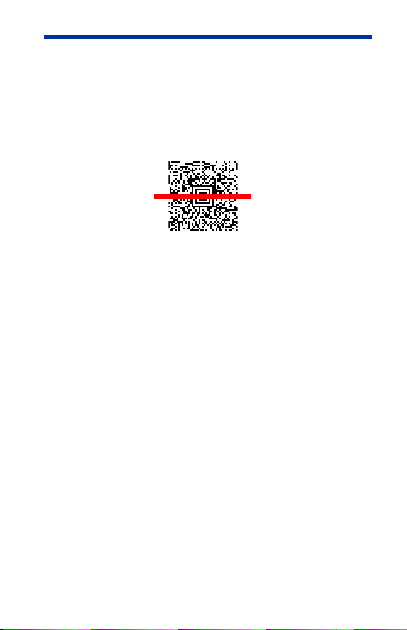
• The hand-held imager has a view finder that projects a bright aiming beam
that corresponds to the imager’s horizontal field of view. The aiming beam
should be centered over the bar code and positioned horizontally over the
code (no tilt, skew, or rotation). If the symbol surface is shiny, the reader
may have to be held several degrees below the normal position to avoid
specular reflections.
2D Matrix symbol
• When testing, attempt to minimize as much movement of the imager as possible. Excessive movement can cause variability in PQA results.
• It is best to take multiple reads of the symbol, comparing the PQA results to
form a better indication of the overall symbol quality.
When you use 2D PQA under the above conditions, you can expect meaningful
and repeatable results that can be used to make correction adjustments in your
symbol generation process.
Symbology/Parameter Specifics
Two-dimensional bar code symbologies come in three distinct varieties or basic
structures:
1. Stacked or Multi-Row symbologies (e.g., PDF417 and MicroPDF47),
2. 2D Matrix symbologies (e.g., Data Matrix, Aztec Code, QR Code, and Maxicode), and
3. Postal (Height-Modulated) symbologies (e.g., Postnet and Planet Code in
the U.S. and the 4-State codes used in England, the Netherlands (KIX),
Canada, Japan, and Australia).
Since each of these basic types or structures differ, the 2D PQA outputs are
quite different to accommodate the quality parameters for each of the classes of
2D symbols.
1 - 2
Page 7
2D PQA Reporting
Full Report
HHP's 2D PQA reporting can be enabled in two different modes: Full Report or
Screening.
If you are using Quick*View, you can enable Full Report, a listing of all of a symbol's identifying information, measurements, and corresponding grades, by typing the following menu command:
2D_PQA1
or by scanning the following bar code:
Full Report
Note: With the IT4600/4800/4X80, the PQA report is sent out as a second data/
beep sequence after the bar code data. The report has its own HHP code
ID of >(0X3E) so it can be uniquely identified.
Screening Report
Screening is a grade-based mode that allows display of a limited list of identifying information, as well as only those measurements that are below Minimum
Acceptable Grade (MAG) level. With the IT4600/4800/4X80, if all of the parameters are met in the screening mode, only the bar code data will be output with a
beep. If one or more of the measured parameters fail to meet the MAG, the
PQA message is also sent with a beep.
Note: With the IT4410/4710, screening mode outputs are also accompanied by
a single beep if all parameters are okay or a triple beep if one or more of
the measured parameters fail to meet the MAG.
If you are using Quick*View, you can enable Screening by typing the following
menu commands:
2D_PQA2 when A is the Minimum Acceptable Grade
2D_PQA3 when B is the Minimum Acceptable Grade
2D_PQA4 when C is the Minimum Acceptable Grade
2D_PQA5 when D is the Minimum Acceptable Grade
1 - 3
Page 8
If your imager is in keyboard wedge mode, enable Screening by scanning the
following bar codes.
Minimum Acceptable
Grade = A
Minimum Acceptable
Grade = C
You can exit both Full Report and Screening modes by either typing the menu
command, 2D_PQA0, if you are using Quick*View, or by scanning the following
bar code:
Exit
Minimum Acceptable
Grade = B
Minimum Acceptable
Grade = D
Identifying Symbol Content
To identify content or "format" aspects of a symbol, 2D PQA modes report the
less than obvious characteristics of a symbol. For quality determination, 2D
PQA reports those parameters that both relate directly to the print or creation
process, and that also remain relatively consistent over a range of hand held
reading situations.
In the 2D PQA Full Report mode, successful scans of a 2D symbol output a
message similar to the following (with slight variations based upon the symbology being tested):
This is a representative PDF417 symbol
>>> PQA from HHP <<<
PDF417: 11 rows x 3 cols, 25 data & 8 chks (ECL = 2)
X roughly = 0.014"
[A] < Row Height = 3.1 X
[A] < Useful Row Height = 2.5 X (82% Row)
[A] < Data Safety Margin = 100% (0 Erasures & 0 Errors)
[B] < Edge Accuracy = 59%
[C] < Print Growth = -43% of X
1 - 4
Page 9

While the details are explained below, this general format includes:
• the encoded data (the usual output message) in the first line.
• a banner " >>> PQA from HHP <<<" identifying the start of the 2D PQA
report.
• the symbology, its features, and approximate size.
• graded print quality parameters in the following lines.
In the 2D PQA Screening mode with "A" as the Minimum Acceptable Grade, this
same scan would be accompanied by a triple beep and the following output
message:
This is a representative PDF417 symbol
>>> PQA from HHP <<<
Minimum Acceptable Grade = A
PDF417: X roughly = 0.014"
Poor Edge Accuracy (59%)
Excessive Print Shrinkage (-43% of X)
With "C" as the Minimum Acceptable Grade, this same scan would produce just
a single beep and the following output message:
This is a representative PDF417 symbol
>>> PQA from HHP <<<
Minimum Acceptable Grade = C
PDF417: X roughly = 0.014"
All Measurements within range
The actual details of the symbol identifying and print quality parameters are
explained in the following sections.
2D Stacked / Multi-row
This section describes 2D PQA outputs for PDF417 and MicroPDF417, as well
as their derivative 2D arrays used in UCC/EAN Composite Components and
T-Linked Code 39.
PDF417
The Full Report from a typical scan looks like the following (line numbers have
been added in curly brackets):
{1} This is a representative PDF417 symbol
{2} >>> PQA from HHP <<<
{3} PDF417: 11 rows x 3 cols, 25 data & 8 chks (ECL = 2)
{4} X roughly = 0.014"
1 - 5
Page 10

{5} [A] < Row Height = 3.1 X
{6} [A] < Useful Row Height = 2.5 X (82% Row)
{7} [A] < Data Safety Margin = 100% (0 Erasures & 0
Errors)
{8} [B] < Edge Accuracy = 59%
{9} [C] < Print Growth = -43% of X
where:
{1} is always the Encoded Message, the usual data output. In this case "This
is a representative PDF417 symbol".
{2} is a standard Banner heading that marks the start of the PQA portion of the
output.
{3} identifies the Symbology, PDF417 (or its derivative COMPOSITE-C), and
lists other characteristics of this symbol: the height and width of the data
field, the numbers of data and check characters, and the corresponding
Error Correction Level.
{4} presents an approximate X-dimension, presuming normal viewing dis-
tance.
In the Screening PQA modes, the Symbology Identification from Line {3} is combined with the approximate X-dimension from Line {4}.
Note: The reported X-dimension is approximate and based upon use of the
IT4410LR at 4.7 in (12 cm) (see "Reading Techniques" on page 1-1). If
you use different image engines, the X-dimension will vary. If you hold
the reader closer than 4.7 in (12 cm), it will have the effect of reporting a
larger than true X-dimension. Conversely, if you hold the reader farther
away than 4.7 in (12 cm), it will have the effect of reporting a smaller than
true X-dimension. Please contact HHP Application Support for additional
information. Refer to Chapter 3 for contact information.
{5} lists the average Row Height, assigning the grades as:
A if Row Height >= 2.5 X
Fotherwise
In Screening modes, this parameter is reported as "Rows are Too Short (2.2X)"
when that is the case.
{6} lists the Useful Row Height, which is the measured Row Height times the
codeword yield (listed in parentheses), the percentage of symbol characters
scanned that actually decode. The grade is assigned as:
A if Useful Height >= 2.0 X, else
B if Useful Height >= 1.6 X, else
C if Useful Height >= 1.3 X, else
1 - 6
Page 11

D if Useful Height >= 1.0 X, else
Fotherwise
In Screening modes, this parameter is reported as "Useful Row Height is Too
Short (1.5X)" when that is the case.
{7} lists the Data Safety Margin, which is the ratio of the unused error correc-
tion words to the recommended (!) number of such words. Data Safety Margin can exceed 100%, when the ECL is higher than the minimum
recommended, or be limited to 50% or lower, even with perfect printing,
when the ECL is below minimum. The grade is assigned as:
A if Safety Margin >= 62%, else
B if Safety Margin >= 50%, else
C if Safety Margin >= 37%, else
D if Safety Margin >= 25%, else
Fotherwise
In Screening modes, this parameter is reported as "Low Data Safety Margin
(44%)" when that is the case.
{8} lists the Edge Accuracy measured in the Start or Stop patterns. The grade
is assigned as:
A if Edge Accuracy >= 62%, else
B if Edge Accuracy >= 50%, else
C if Edge Accuracy >= 37%, else
D if Edge Accuracy >= 25%, else
Fotherwise
In Screening modes, this parameter is reported as "Poor Edge Accuracy (59%)"
when that is the case.
{9} lists the Print Growth measured in the Start or Stop patterns (the growth of
the dark modules or "bars"). The grade is assigned as:
A if Print Growth is between +/- 20%, else
B if Print Growth is between +/- 30%, else
C if Print Growth is between +/- 40%, else
D if Print Growth is between +/- 50%, else
Fotherwise
In Screening modes, this parameter is reported as "Excessive Print Growth
(33%)" or "Excessive Print Shrinkage (-43%)" when those are the cases.
1 - 7
Page 12

In rare instances where neither a valid Start nor Stop pattern is measurable, yet
the symbol is somehow read, lines {8} and {9} are replaced by a message to
that effect. The message is either:
"[F] < Start/Stop Decode Fails" in a Full Report
or
"Start/Stop Characters are Bad" in a Screening mode.
In Screening modes, it often occurs that none of the parameters are below the
Minimum Acceptable grade. In this case, the final PQA line becomes:
"All Measurements within range".
MicroPDF417
The Full Report from a typical scan looks like the following (line numbers have
been added in curly brackets):
{1} This is a typical Micro PDF417 symbol
{2} >>> PQA from HHP <<<
{3} MICROPDF: 15 rows x 3 cols, 24 data & 21 chks
{4} X roughly = 0.015"
{5} [A] < Row Height = 1.8 X
{6} [A] < Data Safety Margin = 100% (0 Erasures & 0
Errors)
{7} [A] < Edge Accuracy = 70%
{8} [A] < Print Growth = +4% of X
where:
{1} is the Encoded Message.
{2} is the Banner heading.
{3} identifies the Symbology, MICROPDF (or one of its derivatives: COMPOS-
ITE-A, COMPOSITE-B, or TLC39), and lists other characteristics of this
symbol: the height and width, and the numbers of data and check, or error
correction characters.
{4} presents an approximate X-dimension.
Note: The reported X-dimension is approximate and based upon use of the
IT4410LR at 4.7 in (12 cm) (see "Reading Techniques" on page 1-1). If
you use different image engines, the X-dimension will vary. If you hold
the reader closer than 4.7 in (12 cm), it will have the effect of reporting a
larger than true X-dimension. Conversely, if you hold the reader farther
away than 4.7 in (12 cm), it will have the effect of reporting a smaller than
true X-dimension. Please contact HHP Application Support for additional
information. Refer to Chapter 3 for contact information.
{5} lists the average Row Height, assigning the grades as:
1 - 8
Page 13

A if Row Height >= 1.5 X,
Fotherwise.
{6} lists the Data Safety Margin. Because MicroPDF's error correction level is
fixed, this parameter is just the "Unused Error Correction" and always
between 0 and 100%.
{7} lists the Edge Accuracymeasured in multiple scans through the Row
Address Patterns.
{8} lists the Print Growth measured within the Row Address Patterns.
2D Matrix
This section describes 2D PQA outputs for Aztec Code, Data Matrix, QR Code,
and MaxiCode.
Aztec Code
The Full Report from a typical scan looks like the following (line numbers have
been added in curly brackets):
{1} This is a representative Aztec Code symbol
{2} >>> PQA from HHP <<<
{3} AZTEC CODE: 3 layers (Compact) => 23x23 modules
{4} Data Field: 29 data & 22 chks in GF(256), 0 Erasures
& 0 Errors
{5} X roughly = 0.021"
{6} [A] < Core Symbol: 0 errors
{7} [A] < Data Safety Margin = 146%
{8} [A] < Horizontal Print Growth = +1% of X
{9} [A] < Vertical Print Growth = +1% of X
{1} is the Encoded Message.
{2} is the Banner heading.
{3} identifies the Symbology (AZTEC CODE) and lists the symbol's size and
format.
{4} lists the numbers of Data and Check Words, as well as the Error Correction
used.
{5} presents an approximate X-dimension.
1 - 9
Page 14

Note: The reported X-dimension is approximate and based upon use of the
IT4410LR at 4.7 in (12 cm) (see "Reading Techniques" on page 1-1). If
you use different image engines, the X-dimension will vary. If you hold
the reader closer than 4.7 in (12 cm), it will have the effect of reporting a
larger than true X-dimension. Conversely, if you hold the reader farther
away than 4.7 in (12 cm), it will have the effect of reporting a smaller than
true X-dimension. Please contact HHP Application Support for additional
information. Refer to Chapter 3 for contact information.
{6} lists the number of Module Errors in the central Core Symbol, which con-
sists of the finder bullseye, four orientation clusters at its corners, and the
mode message along its perimeter. The grade is assigned as:
A if there are 0 (zero) errors,
B if there is 1 error,
C if there are 2 errors,
D if there are 3 errors
F if there are 4 or more errors.
In Screening modes, this parameter is reported as "Too many Code Symbol
Errors (3)" when that is the case.
{7} lists the Data Safety Margin. In Aztec Code symbols, the recommended
number of error correction words is a minimum that is generally exceeded
because any excess codeword capacity is filled with extra check words.
Thus this parameter often exceeds 100%, but it also can be forced to much
higher or lower levels by user options.
{8} and {9} list the Horizontal & Vertical Print Growths, respectively. When
one direction's growth is substantially larger than the other, excessive bar
dragging in the direction of label travel is indicated and should be fixed.
When both directions have excessive growth, then either (a) adjustment of
the print process or (b) undercutting of the original bar code symbol graphic
is recommended.
Data Matrix
The Full Report from a typical scan looks like the following (line numbers have
been added in curly brackets):
{1} This is a representative Data Matrix symbol
{2} >>> PQA from HHP <<<
{3} DATA MATRIX ECC200: 24 x 24 modules in size
{4} Data Field: 36 data & 24 chks in 1 block(s) of
GF(256)
{5} X roughly = 0.025"
{6} [A] < Fixed Patterns: 0 module errors
1 - 10
Page 15

{7} [A] < Data Safety Margin = 100%
{8} [A] < Horizontal Print Growth = +10% of X
{9} [A] < Vertical Print Growth = +12% of X
{1} is the Encoded Message.
{2} is the Banner heading.
{3} identifies the Symbology (DATA MATRIX) and lists the symbol's ECC and
size.
{4} lists the numbers of Data and Check Words, as well as the error correction
used.
{5} presents an approximate X-dimension.
Note: The reported X-dimension is approximate and based upon use of the
IT4410LR at 4.7 in (12 cm) (see "Reading Techniques" on page 1-1). If
you use different image engines, the X-dimension will vary. If you hold
the reader closer than 4.7 in (12 cm), it will have the effect of reporting a
larger than true X-dimension. Conversely, if you hold the reader farther
away than 4.7 in (12 cm), it will have the effect of reporting a smaller than
true X-dimension. Please contact HHP Application Support for additional
information. Refer to Chapter 3 for contact information.
{6} lists the number of Module Errors in the Fixed Patterns, which consist of
the Finder "L" and Clocking tracks around the perimeter of the symbol, their
adjacent quiet zones, and any interior alignment patterns in larger ECC200
symbols.
In Screening modes, this parameter is reported as "Too many Fixed Pattern
Errors (3)" when that is the case.
{7} lists the Data Safety Margin. This parameter is measured and reported
only for ECC200 symbols. These symbols have a fixed level of error correction. There is no equivalent parameter for the convolutional error encoding
used in older versions of Data Matrix. This parameter is just the "Unused
Error Correction" and always between 0 and 100%.
{8} and {9} list the Horizontal & Vertical Print Growths, respectively.
QR Code
The Full Report from a typical scan looks like the following (line numbers have
been added in curly brackets):
{1} This is a representative QR Code symbol
{2} >>> PQA from HHP <<<
1 - 11
Page 16

{3} QR CODE: Model 2 Version 3 (29 x 29 modules)
{4} Mask Pattern Reference #3, Error Correction Level
"M"
{5} Data Field: 44 data & 26 checks in 1 block(s) of
GF(256)
{6} X roughly = 0.025"
{7} [A] < Data Safety Margin = 100%
{8} [A] < Horizontal Print Growth = +20% of X
{9} [A] < Vertical Print Growth = +17% of X
{1} is the Encoded Message.
{2} is the Banner heading.
{3} identifies the Symbology (QR CODE) and lists the symbol's model, version
and size.
{4} lists this symbol's Mask Pattern and Error Correction Level.
{5} lists the numbers of Data and Check Words and their arrangement into
blocks.
{6} presents an approximate X-dimension.
Note: The reported X-dimension is approximate and based upon use of the
IT4410LR at 4.7 in (12 cm) (see "Reading Techniques" on page 1-1). If
you use different image engines, the X-dimension will vary. If you hold
the reader closer than 4.7 in (12 cm), it will have the effect of reporting a
larger than true X-dimension. Conversely, if you hold the reader farther
away than 4.7 in (12 cm), it will have the effect of reporting a smaller than
true X-dimension. Please contact HHP Application Support for additional
information. Refer to Chapter 3 for contact information.
{7} lists the Data Safety Margin. "M" is the recommended error correction
level for QR Code, so symbols encoded at "H" or "Q" will typically have
safety margins exceeding 100%, while those encoded at "L" are limited to
values below 50%.
{8} and {9} list the Horizontal & Vertical Print Growths, respectively.
MaxiCode
The Full Report from a typical scan looks like the following (line numbers have
been added in curly brackets):
{1} This is a representative Maxicode symbol
{2} >>> PQA from HHP <<<
{3} MAXICODE: Mode 4
1 - 12
Page 17

{4} X roughly = 0.043"
{5} [A] < Data Safety Margin = 100%
{6} [A] < Horizontal Print Growth = +2% of X
{7} [A] < Vertical Print Growth = -1% of X
{1} is the Encoded Message.
{2} is the Banner heading.
{3} identifies the Symbology (MAXICODE) and lists the symbol's Mode.
{4} presents an approximate X-dimension.
Note: The reported X-dimension is approximate and based upon use of the
IT4410LR at 4.7 in (12 cm) (see "Reading Techniques" on page 1-1). If
you use different image engines, the X-dimension will vary. If you hold
the reader closer than 4.7 in (12 cm), it will have the effect of reporting a
larger than true X-dimension. Conversely, if you hold the reader farther
away than 4.7 in (12 cm), it will have the effect of reporting a smaller than
true X-dimension. Please contact HHP Application Support for additional
information. Refer to Chapter 3 for contact information.
{5} lists the Data Safety Margin. Because the Error Correction level for Maxi-
Code is fixed for each mode, this parameter is just the "Unused Error Correction," and is always between 0 and 100%.
{6} and {7} list the Horizontal & Vertical Print Growths, respectively.
Postal (Height-Modulated) Bar Code Symbologies
This section describes the height-modulated 2-state symbologies, Postnet and
Planet Code, used in the United States, as well as the 4-state symbologies used
in England, the Netherlands (“KIX”), Canada, Japan, and Australia. All dimensions, where listed, are in inches for 2-state symbols and in millimeters for 4state symbols.
Postnet and Planet Code
The Full Report from a typical scan looks like the following (line numbers have
been added in curly brackets):
{1} 51591
{2} >>> PQA from HHP <<<
{3} POSTNET: 32 Bars, nominally from 01.30 to 01.56 in.
in Width
{4} Bar Sequence: 10101000011010101010000011101001
{5} [F] (Hi) < Tall Bar Heights: 0.155 in.
{6} [F] (Hi) < Short Bar Heights: 0.081 in.
1 - 13
Page 18

{7} [A] (Ok) < Bar Widths = 0.022 in.
{8} [A] (Ok) < Inter-Bar Gaps = 0.023 in.
{1} is the Encoded Message.
{2} is the Banner heading.
{3} identifies the Symbology, (POSTNET or PLANET Code), and lists also the
symbol's size and allowed range of measured width.
{4} lists the Bar Sequence, "1" representing a tall bar and "0" representing a
short one.
{5} lists the Average Height of the tall bars, specified to fall within 0.115 to
0.125 in. The grades are assigned as:
A if within the middle 67% of the specified tolerances, else
B if within the specified tolerances, else
C if within a range 25% wider(!) than the specified tolerances, else
D if within a range 50% wider(!) than the specified tolerances, else
Fotherwise
Note: These forgiving grade assignments, employed throughout the postal
symbologies, reflect what are generally tight and unforgiving print
specifications.
In Screening modes, this parameter is reported as ""Tall" Bars are too Short (or
Long) (0.xxx in.)" when that is the case.
{6} lists the Average Height of the short bars, specified to fall within 0.040 to
0.060 in.
In Screening modes, this parameter is reported as ""Short" Bars are too Short
(or Long) (0.xxx in.)" when that is the case.
{7} lists the Average Width of the bars, specified to fall within 0.015 to 0.025 in.
In Screening modes, this parameter is reported as "Bars are too Narrow (or
Wide) (0.xxx in.)" when that is the case.
{8} lists the Average Space Width between bars, specified to fall within 0.012
to 0.040 in.
In Screening modes, this parameter is reported as "Spaces are too Narrow (or
Wide) (0.xxx in.)" when that is the case.
1 - 14
Page 19

4-State Codes
The Full Report from a typical scan looks like the following (line numbers have
been added in curly brackets):
{1} B15AJ6T
{2} >>> PQA from HHP <<<
{3} 4-STATE(British): 34 Bars, nominally from 38.5 to
42.3 mm. in Width
{4} Bar Sequence: ADHTATDAHDDAADADAADTHTADHHDATHTADH
{5} [A] (Ok) < "Tall" Bar Extensions: 2.79 mm. from cen-
ter
{6} [F] (Hi) < "Short" Bar Extensions: 1.00 mm. from
center
{7} [B] (Hi) < Bar Widths = 0.60 mm.
{8} [A] (Ok) < Inter-Bar Gaps = 0.59 mm.
{1} is the Encoded Message.
{2} is the Banner heading.
{3} identifies the Symbology, 4-STATE (British, or KIX, Canadian, Japanese,
or Australian), and also lists this symbol's size and allowed range of measured width.
{4} lists the Bar Sequence, "A" representing Ascending bars, "D" representing
Descending bars, "T" representing Tracker (short) bars, and "H" representing tall bars that both ascend and descend.
{5} lists the Average Extension from the centerline of the tall ascenders and
descenders, as specified in Table 1.
In Screening modes, this parameter is reported as ""Tall" Bar Extensions are
too Short (or Long) (0.xxx in.)" when that is the case.
{6} lists the Average Extensions from the centerline of the Short tracks, as
specified in Table 1.
In Screening modes, this parameter is reported as "Short" Bar Extensions are
too Short (or Long) (0.xxx in.)" when that is the case.
{7} lists the Average Width of the bars, as specified in Table 1.
{8} lists the Average Space Width between bars, as specified in Table 1.
1 - 15
Page 20

Note: For the Canadian and Australian 4-State symbologies only, any bar error
that has invoked their error correction triggers an additional PQA
parameter line:
"[F] < One or more Bars are in Error!" in a Full Report or
"One or more Bars are in Error!" in a Screening mode.
Table 1: Dimensional Tolerances for the Various 4-State Bar
Code Symbologies
“Tall” Bar
Extensions
British 2.16 - 2.92 mm 0.51 - 0.76 mm 0.38 - 0.63 mm 0.50 - 0.87 mm
Netherlands 2.16 - 2.92 mm 0.51 - 0.76 mm 0.38 - 0.63 mm 0.42 - 0.89 mm
Canadian 2.1 - 2.50 mm 0.25 - 0.40 mm 0.40 - 0.60 mm 0.40 - 0.76 mm
Japanese 1.70 - 1.80 mm 0.52 - 0.68 mm 0.50 - 0.70 mm 0.45 - 0.60 mm
Australian 2.10 - 2.90 mm 0.50 - 0.80 mm 0.40 - 0.60 mm 0.40 - 0.76 mm
“Short” Bar
Extensions”
Bar Widths
Gap (Space)
Widths
Parameter Interpretation
Average Bar/Gap Width
Average Bar or Inter-Bar Gap Widths are the average of such dimensions measured across an entire postal symbology. A low average bar width or inter-bar
gap width grade indicates print conditions that expand or shrink the apparent
size of the dark elements, threatening to make the narrow bars or spaces disappear. Potential areas of correction include adjusting the print process (e.g., ink
flow, transfer heat, print speed), adjusting the original bar code symbol graphic
or pattern (through techniques such as undercutting), or by making the symbol
larger.
Average (Bar) Height/Extension Height
Average Height/Extension Height is a measure of the average height of the bars
or dark elements in a symbol. Depending on the symbology and print process,
this can be corrected by graphically stretching the symbol for 2D stacked symbols (see "Row Height" on page 1-19 and "Useful Row Height" on page 1-19),
or may be an indication that the symbol generating program, in the case of the
postal symbologies, does not meet the required specifications.
1 - 16
Page 21

Bar Sequence
Bar Sequence is the bar height pattern within a height modulated, multi-state,
postal-type symbology. In a 2-state symbol, a "1" represents a tall or full height
bar and a "0" represents a short or half height bar. In a 4-state symbol, "A" represents the ascending bars, "D" the descending bars, "T" the short bars, and "H"
the tall bars that both ascend and descend. Incorrect sequencing can be systematic and can be caused by the symbol generating program not meeting
requirements.
Codeword (Data and Check)
A Codeword is a symbol character value or intermediate level of coding
between source data and the graphical encodation in the symbol. A data codeword encodes data according to the rules or scheme of the symbology, where
check codewords are reserved for error detection/correction purposes.
Codeword Yield
Codeword Yield is an indication of the interference between adjacent rows in a
2D stacked symbology. A low Codeword Yield can indicate print conditions
where this interference is caused by drag, streaking, or other situations where
there is carry-over of ink from one row to another (see "Useful Row Height" on
page 1-19).
Data Safety Margin
Data Safety Margin is the ratio of the unused error correction codewords to the
recommended number of error correction codewords. A low Data Safety Margin indicates a symbol that is close to reading failure and can be improved by
improving the printing, correcting the cause of bad or missing symbol characters
(e.g., spots, voids), or by raising the Error Correction Level (ECL).
Edge Accuracy
Edge Accuracy is a measure of the accuracy of the bar or dark element edge
positions within the symbol. A low Edge Accuracy indicates print conditions,
such as a "print pitch to X-dimension" mismatch or general edge irregularities
(but not uniform print growth), which can harm character decoding. The first
condition is improved by properly scaling the symbol to the print pitch, and both
conditions are improved by making the symbol larger.
1 - 17
Page 22

Encoded Message
The encoded message is the information (alpha, numeric, and/or control characters) or message contained within the bar code symbol and output as part of
the decoding process. This information precedes the calculated PQA parameters. This information must be manually compared to the characters that should
be encoded.
Error Correction/Error Correction Characters
Error Correction is a reader/decoder’s use of mathematical processes to reconstruct or replace damaged or missing symbol characters. Error correction characters are specific symbol characters that are created automatically from the
other symbol data characters and used for error correction and detection.
Error Correction Level (ECL)
Error Correction Level is an indication of the number of characters used in a
symbology for the purpose of error correction. Higher levels of error correction
allow for correcting greater potential symbol damage.
Error Detection/Error Detection Characters
Error Detection is the use of error correction characters (symbol characters that
are reserved for error detection and calculated automatically from the other
symbol characters) to detect whether the presence of errors in the symbol
exceeds the error correction capacity. Error detection will keep the symbol from
being decoded as erroneous data.
Mask Pattern/Masking
Mask Pattern/Masking is a specific part or characteristic of QR Code where a
process is used to provide a more evenly balanced number of light and dark
modules to reduce the occurrence of arrangements of adjoining modules that
might interfere with efficient processing of a symbol's image. For additional
information, refer to the QR Code symbology, available from AIM Global Specification (www.aimglobal.org).
1 - 18
Page 23

Module Errors
Module Errors are individual errors within fixed pattern/data areas. Although
often benign, Module Errors in the fixed regions of a symbol can signal a fault
that, in some instances, will prevent proper decoding. They can generally be
corrected by using a larger X-dimension and/or cleaning up the print process to
eliminate stray ink, voids, and other causes of inconsistency in the print.
Print Growth (Horizontal and Vertical)
Print Growth is a measure of the growth or shrinkage of the bar widths (2D
stacked) or element/module (2D matrix) width and/or height. A low Print Growth
grade indicates print conditions that expand or shrink the apparent size of the
dark bars or elements, which can cause them to optically disappear. In 2D
matrix symbols, if the growth/shrinkage in one direction is larger than the other,
this can indicate excessive drag in the direction of label travel. Potential areas
of correction include adjusting the print process (e.g., ink flow, transfer heat,
print speed), adjusting the original bar code symbol graphic or pattern (through
techniques such as undercutting), or by making the symbol larger.
Row Height
Row Height is an approximate measure of the average height of the elements in
a row, which indicates growth or shrinkage of the element widths. In 2D stacked
symbologies, row heights of less than the recommended height can impede
hand held scanning. This can be corrected by graphically stretching the symbol.
Symbology
Symbology is the symbology type that has been tested. A symbology is a standard means of representing data in a bar code form. Each symbology specification sets out its particular rules of composition or data architecture.
Useful Row Height
Useful Row Height is the measured Row Height times the Codeword Yield. A
low Useful Row Height usually indicates print conditions where rows interfere
with their adjacent neighboring rows, creating a dead band of wasted scanning
in between. Useful row height scales these interfering rows to the printed row
1 - 19
Page 24

height, giving more leeway to symbols printed with above minimum row heights
(e.g., 4.0 X). A poor grade here is corrected by either stretching the symbol vertically or correcting the print condition (e.g., turning down the thermal burn setting or adjusting inking) that causes rows to interfere.
X-dimension
The X-dimension is an approximate measure of the average width of the narrow
elements in a 2D stacked bar code symbol or a single element or module in a
2D matrix symbol, and indicates growth or shrinkage of the element widths.
1 - 20
Page 25

2
Quick*View
Quick*View Demonstration Software Instructions
Quick*View is a Microsoft Windows® program that displays decoded symbol
messages and captures images (for instance, ID photographs) from the imager.
Bar code information and images are displayed in the Quick*View window.
Note: For additional information about Quick*View, please refer to the user’s
guide for your imager.
Setting Up the Imager and the Quick*View Software
1. Connect the Imager to the PC’s com port (com port 1 or com port 2) via the
appropriate interface cable (refer to the user’s guide for your imager). Connect the appropriate power supply to the Imager. (The Imager cannot get its
power from the PC’s com port.)
2. Insert the SDK CD. Load Quick*View from the CD.
For Microsoft Windows 95 or NT 4.0
3. Insert the Quick*View diskette labelled “32 Bit Release” into Drive A or B.
4. From the Start Menu, click on Run. Type “x:\setup” in the command line
box, where “x” represents a drive letter, typically “A” for the 3.5" floppy drive
on most PCs. Click on OK.
5. Follow the instructions in the setup screens.
6. To start the Quick*View program, from the Start Menu click on Programs,
Quickview, QuickView (32 Bit).
Installing Quick*View from the Web
1. Access the HHP web site at www.hhp.com.
2. Click in the Quick Search text box and enter Quick*View.
3. Click on Search Now.
4. Click on the entry for Quick*View.
5. When prompted, select Save File, and save the files to the c:\win-
dows\temp directory.
6. Once you have finished downloading the file, exit the web site.
7. Using Explorer, go to the c:\windows\temp file.
2 - 1
Page 26

8. Double click on the Quickview.exe file. Follow the screen prompts to install
the Quick*View program.
9. To start Quick*View, from the Start Menu click on Programs, Quick*View,
Quick*View.
Note: If you wish, you can create a shortcut to the Quick*View executable on
your desktop.
Temporary Quick*View Configuration
For a quick download communication configuration, scan the appropriate
Quick*View bar code, and the imager will be temporarily configured for
Quick*View settings.
Note: If you have a unit capable of keyboard wedge mode, scan the bar code
below. The unit will communicate in RS-232 mode, allowing it to work with
Quick*View through an appropriate serial cable. To convert the imager
back to keyboard wedge communication, cycle the power.
IT4600/4800/4X80
Quick*View
IT4410/4710
2 - 2
Quick*View
Page 27

Using the Quick*View Software
Upon startup, the Quick*View splash screen appears for approximately three
seconds. Quick*View will then attempt to establish communications with the
Imager.
If Communication Cannot Be Established
This message appears if communication cannot be established:
Quick*View defaults to com 1 as the communications port. If you have plugged
the Imager into another com port, you must Cancel out of this message.
Click on File - Preferences. This popup appears:
Click on the
radio button for
the appropriate
com port, then
click on OK.
Quick*View
should now be
able to locate
the Imager.
You may also need to pull the Imager’s trigger to establish communications
between the PC and the Imager.
If you want Quick*View to search for the Imager and establish communication,
click on Device - Auto Baud Detect.
2 - 3
Page 28

Scan Data Window
Once successful communication has been established, you can scan codes and
display the bar code data in a window. Select View - Scan Data Window.
As you scan bar codes, the data appears in the Serial Scan Data Window.
You can alter the font in this window by using the Font button, or clear all data in
the window with the Clear button.
If you wish to see the mnemonic for any embedded control characters, you
should put a check in the checkbox for Expand Control Chars (the default
setting). If you wish to see the ASCII control character rather than the mnemonic,
turn off this checkbox.
Note: The ASCII control character that is displayed is dependent on the font you
are using.
2 - 4
Page 29

3
Customer Support
Obtaining Factory Service
HHP provides service for all its products through service centers throughout the
world. To obtain warranty or non-warranty service, return the unit to HHP
(postage paid) with a copy of the dated purchase record attached. Contact the
appropriate location below to obtain a Return Material Authorization number
(RMA #) before returning the product.
North America
HHP Corporate Offices
Telephone: (800) 782-4263, Option 3
Fax: (704) 566-9904
E-mail: ProductService@HHP.com
Latin America
HHP Latin America
Telephone: (941) 263-7600
Fax: (941) 263-9689
Brazil
HHP Brazil
Telephone: +55 (21) 2494-7060
Fax: +55 (21) 2494-5033
E-mail: suporte@HHP.com.br
Europe, Middle East, and Africa
HHP Europe
Telephone:+ 31 (0) 40 29 01 633
Fax: + 31 (0) 40 2901631
E-mail: EuroService@HHP.com
Asia Pacific
HHP Asia/Pacific
Telephone: +852-2511-3050
Fax: +852-251-13557
E-mail: chuie@HHP.com
Japan
HHP Japan
Telephone: +81-3-5842-6325
Fax: +81-3-5842-6335
E-mail: kobayashit@HHP.com
3 - 1
Page 30

Technical Assistance
If you need assistance installing or troubleshooting your imager, please call your
Distributor or the nearest HHP technical support office:
North America/Canada:
Telephone: (315) 685-2476, Option 4 (8 a.m. to 6 p.m. EST)
or in the U.S. (800) 782-4263
Fax number: (315) 685-4960
E-mail: support@
Europe, Middle East, and Africa:
TelephoneEuropean Ofc: Int+31 (0) 40 29 01 600
U.K. Ofc: Int+44 1925 240055
E-mail: euro_support@
Asia:
Telephone: Int+852-2511-3050
E-mail: asia_support@
Latin America:
Telephone: (239) 263-7600
E-mail: la_support@
HHP
.com
HHP
HHP
HHP
.com
or
2511-3132
.com
.com
3 - 2
Page 31

Page 32

QC2DPQA-UG Rev B
 Loading...