


3800G
™
User’s Guide
3800g
Retail/Commercial Handheld Linear Imager

Disclaimer
Hand Held Products, Inc. (“Hand Held Products”) reserves the right to make
changes in specifications and other information contained in this document
without prior notice, and the reader should in all cases consult Hand Held
Products to determine whether any such changes have been made. The
information in this publication does not represent a commitment on the part of
Hand Held Products.
Hand Held Products shall not be liable for technical or editorial errors or
omissions contained herein; nor for incidental or consequential damages
resulting from the furnishing, performance, or use of this material.
This document contains proprietary information that is protected by copyright. All
rights are reserved. No part of this document may be photocopied, reproduced,
or translated into another language without the prior written consent of Hand
Held Products.
©2006 Hand Held Products, Inc. All rights reserved.
Web Address: www.handheld.com

Statement of Agency Compliance
This device complies with part 15 of the FCC Rules. Operation is subject to the
following two conditions: (1) this device may not cause harmful interference, and
(2) this device must accept any interference received, including interference that
may cause undesired operation.
FCC Class B Compliance Statement
This equipment has been tested and found to comply with the limits for a Class
B digital device pursuant to part 15 of the FCC Rules. These limits are designed
to provide reasonable protection against harmful interference in a residential
installation. This equipment generates, uses, and can radiate radio frequency
energy and, if not installed and used in accordance with the instructions, may
cause harmful interference to radio communications. However, there is no
guarantee that interference will not occur in a particular installation. If this
equipment does cause harmful interference to radio or television reception,
which can be determined by turning the equipment off and on, the user is
encouraged to try to correct the interference by one or more of the following
measures:
• Reorient or relocate the receiving antenna.
• Increase the separation between the equipment and receiver.
• Connect the equipment into an outlet on a circuit different from that to which
the receiver is connected.
• Consult the dealer or an experienced radio or television technician for help.
Caution: Any changes or modifications made to this device that are not
expressly approved by Hand Held Products, Inc. may void the user’s authority
to operate the equipment.
Note: To maintain compliance with FCC Rules and Regulations, cables
connected to this device must be shielded cables, in which the cable shield
wire(s) have been grounded (tied) to the connector shell.
Canadian Notice
This equipment does not exceed the Class B limits for radio noise emissions as
described in the Radio Interference Regulations of the Canadian Department of
Communications.
Le present appareil numerique n’emet pas de bruits radioelectriques depassant
les limites applicables aux appareils numeriques de la classe B prescrites dans
le Reglement sur le brouillage radioelectrique edicte par le ministere des
Communications du Canada.

The CE mark on the product indicates that the system has been
tested to and conforms with the provisions noted within the 89/336/
EEC Electromagnetic Compatibility Directive and the 73/23/EEC
Low Voltage Directive.
For CE-related inquiries, please contact:
Hand Held Products, Inc.
Nijverheidsweg 9
5627 BT Eindhoven
The Netherlands
Hand Held Products shall not be liable for use of our product with equipment
(i.e., power supplies, personal computers, etc.) that is not CE marked and does
not comply with the Low Voltage Directive.
LED Safety Statement
This device has been tested in accordance with IEC60825-1 LED safety, and
has been certified to be under the limits of a Class 1 LED device.
UL and cUL Statement
UL and cUL listed: UL60950-1 and CSA C22.2 No.60950-1-03.
C-Tick Statement
Conforms to AUS/NZ 3548.
TÜV Statement
TÜV or GS marked to EN60950 and EN60825-1.
Mexico
Certified.
Patents
Please refer to the product packaging for patent information.
Solids and Water Protection
The 3800g has a rating of IP41, immunity of foreign particles and dripping water.
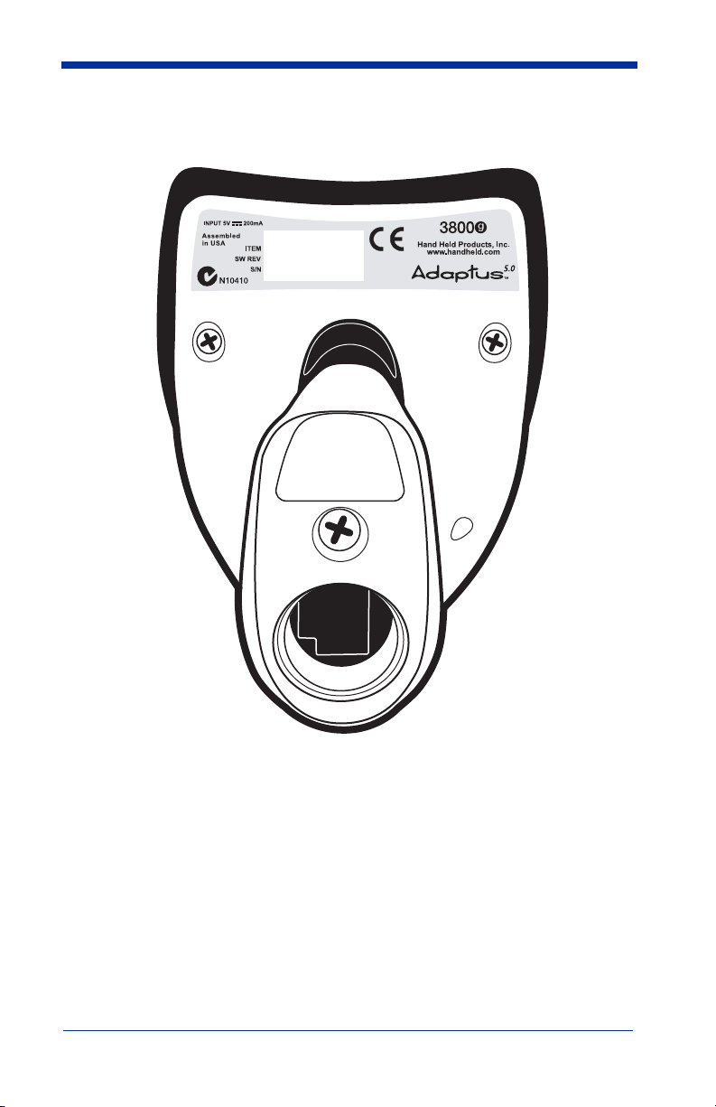
3800g Imager Identification
3800gXXX
XXXXXXXXXX
XXXXXXXXXX


i
Chapter 1 - Getting Started
About This Manual ............................................................... 1-1
Unpacking the Imager........................................................... 1-1
3800g Models ....................................................................... 1-1
Connecting the Imager with USB ........................................ 1-2
USB PC or Macintosh Keyboard ................................... 1-2
IBM SurePos .................................................................. 1-3
USB HID........................................................................ 1-3
USB Com Port Emulation.............................................. 1-3
Plug and Play ........................................................................ 1-4
Connecting the Imager When Powered by Host
(Keyboard Wedge) ............................................................ 1-5
Keyboard Wedge Connection ........................................ 1-5
Laptop Direct Connect ................................................... 1-6
Connecting the Imager with RS-232 Serial Port............ 1-6
IBM 4683 Ports 5B, 9B, and 17 Interface...................... 1-7
Reading Techniques ............................................................. 1-8
Resetting the Standard Product Defaults .............................. 1-8
Chapter 2 - Terminal Interfaces
Terminal ID .......................................................................... 2-1
Supported Terminals............................................................. 2-2
Keyboard Country ................................................................ 2-4
Keyboard Style ..................................................................... 2-5
Keyboard Modifiers.............................................................. 2-6
RS-232 Baud Rate.......................................................... 2-7
RS-232 Word Length: Data Bits, Stop Bits, and Parity. 2-8
RS-232 Handshaking ..................................................... 2-9
Table of Contents

ii
Chapter 3 - Output
Good Read Indicators ........................................................... 3-1
Beeper – Good Read ...................................................... 3-1
Beeper Volume – Good Read ........................................ 3-1
Beeper Pitch – Good Read ............................................. 3-1
Beeper Duration – Good Read ....................................... 3-2
LED – Good Read.......................................................... 3-2
Number of Beeps – Good Read ..................................... 3-2
Good Read Delay.................................................................. 3-3
User-Specified Good Read Delay .................................. 3-3
Trigger Modes ...................................................................... 3-3
Manual/Serial Trigger .................................................... 3-3
Automatic Trigger.......................................................... 3-4
Presentation Mode.......................................................... 3-4
Continuous Illumination Mode ...................................... 3-4
Hands Free Time-Out ........................................................... 3-5
Reread Delay ........................................................................ 3-5
User-Specified Reread Delay......................................... 3-6
Centering Window................................................................ 3-6
Output Sequence Overview .................................................. 3-8
Output Sequence Editor ................................................. 3-9
Require Output Sequence............................................... 3-9
Multiple Symbols ............................................................... 3-11
No Read .............................................................................. 3-11
Video Reverse..................................................................... 3-12
Chapter 4 - Data Editing
Prefix/Suffix Overview......................................................... 4-1
To Add a Prefix or Suffix: 2
To Clear One or All Prefixes or Suffixes:...................... 4-3
To Add a Carriage Return Suffix to all Symbologies .... 4-3
Prefix Selections............................................................. 4-3
Suffix Selections ............................................................ 4-4
Function Code Transmit................................................. 4-4

iii
Intercharacter, Interfunction, and Intermessage Delays ....... 4-4
Intercharacter Delay ....................................................... 4-5
User Specified Intercharacter Delay............................... 4-5
Interfunction Delay......................................................... 4-6
Intermessage Delay ........................................................ 4-6
Chapter 5 - Data Formatting
Data Format Editor Introduction........................................... 5-1
To Add a Data Format.................................................... 5-1
Other Programming Selections ...................................... 5-2
Data Format Editor Commands...................................... 5-2
Data Format Editor......................................................... 5-4
Data Formatter................................................................ 5-5
Alternate Data Formats .................................................. 5-5
Chapter 6 - Secondary Interface
3800g Models........................................................................ 6-1
Enabling the Secondary Interface ......................................... 6-1
Secondary RS-232 Connection ............................................. 6-1
Secondary Trigger Mode ...................................................... 6-2
Hands Free Time-Out ........................................................... 6-3
Chapter 7 - Symbologies
Introduction........................................................................... 7-1
Message Length .................................................................... 7-2
Codabar ................................................................................. 7-3
Codabar Start/Stop Characters....................................... 7-3
Codabar Check Character............................................... 7-3
Codabar Concatenation .................................................. 7-4
Codabar Message Length ............................................... 7-5

iv
Code 39................................................................................. 7-5
Code 39 Start/Stop Characters....................................... 7-5
Code 39 Check Character............................................... 7-6
Code 39 Message Length ............................................... 7-6
Code 39 Append............................................................. 7-7
Full ASCII...................................................................... 7-8
Code 39 Code Page ........................................................ 7-9
Interleaved 2 of 5 .................................................................. 7-9
Check Digit .................................................................... 7-9
Interleaved 2 of 5 Message Length .............................. 7-10
Code 93............................................................................... 7-11
Code 93 Message Length ............................................. 7-11
Code 93 Code Page ...................................................... 7-11
Straight 2 of 5 Industrial ..................................................... 7-12
Straight 2 of 5 Industrial Message Length ................... 7-12
Straight 2 of 5 IATA Message Length......................... 7-13
Matrix 2 of 5 ....................................................................... 7-13
Matrix 2 of 5 Message Length ..................................... 7-14
Code 11............................................................................... 7-14
Check Digits Required ................................................. 7-14
Code 11 Message Length ............................................. 7-15
Code 128............................................................................. 7-15
ISBT 128 Concatenation.............................................. 7-15
Code 128 Message Length ........................................... 7-16
Code 128 Code Page .................................................... 7-16
Code 128 Function Code Transmit .............................. 7-16
Telepen ............................................................................... 7-17
Telepen Output............................................................. 7-17
Telepen Message Length.............................................. 7-17
UPC A................................................................................. 7-18
UPC A Check Digit...................................................... 7-18
UPC A Number System ............................................... 7-18
UPC A Addenda........................................................... 7-18
UPC A Addenda Required ........................................... 7-19
UPC A Addenda Separator .......................................... 7-19

v
UPC E0 and UPC E1 .......................................................... 7-20
UPC E0 and UPC E1 Expand....................................... 7-21
UPC E0 and UPC E1 Addenda Required..................... 7-21
UPC E0 and UPC E1 Addenda Separator .................... 7-21
UPC E0 Check Digit .................................................... 7-21
UPC E0 Number System.............................................. 7-22
UPC E0 Addenda ......................................................... 7-22
EAN/JAN 13....................................................................... 7-22
EAN/JAN 13 Check Digit............................................ 7-23
EAN/JAN 13 Addenda................................................. 7-23
EAN/JAN 13 Addenda Required ................................. 7-23
EAN/JAN 13 Addenda Separator................................. 7-24
ISBN Translate ............................................................. 7-24
EAN/JAN 8......................................................................... 7-24
EAN/JAN 8 Check Digit.............................................. 7-25
EAN/JAN 8 Addenda................................................... 7-25
EAN/JAN 8 Addenda Required ................................... 7-25
EAN/JAN 8 Addenda Separator................................... 7-26
MSI ..................................................................................... 7-26
MSI Check Character ................................................... 7-26
MSI Message Length.................................................... 7-27
Plessey Code ....................................................................... 7-27
Plessey Message Length............................................... 7-27
RSS Limited........................................................................7-28
RSS Expanded .................................................................... 7-29
RSS Expanded Message Length................................... 7-29
China Post Code.................................................................. 7-30
Korea Post Code ................................................................. 7-31
Korea Post Message Length ......................................... 7-31
PosiCode A and B............................................................... 7-31
PosiCode Message Length ........................................... 7-32
Codablock F ........................................................................ 7-33
Codablock F Message Length ...................................... 7-33
Code 16K ............................................................................ 7-34
Code 16K Message Length .......................................... 7-34
Code 49 ............................................................................... 7-34
Code 49 Message Length ............................................. 7-35

vi
Chapter 8 - Interface Keys
Keyboard Function Relationships......................................... 8-1
Supported Interface Keys .................................................... 8-3
Chapter 9 - Utilities
To Add a Test Code I.D. Prefix to All Symbologies............ 9-1
Show Software Revision....................................................... 9-1
Show Data Format ................................................................ 9-1
Resetting the Standard Product Defaults .............................. 9-1
Temporary Visual Xpress Configuration.............................. 9-2
Chapter 10 - Visual Xpress
Visual Xpress Introduction ................................................. 10-1
Installing Visual Xpress from the Web........................ 10-2
Chapter 11 - Serial Programming Commands
Conventions ........................................................................ 11-1
Menu Command Syntax ..................................................... 11-1
Query Commands......................................................... 11-2
Concatenation of Multiple Commands ........................ 11-2
Responses..................................................................... 11-2
Examples of Query Commands ................................... 11-3
Trigger Commands ............................................................. 11-4
Resetting the Standard Product Defaults ............................ 11-4
Menu Commands................................................................ 11-5
Chapter 12 - Product Specifications
3800g Product Specifications ............................................. 12-1
3800g Depth of Field (typical performance) ...................... 12-2
Chapter 13 - Maintenance
Repairs ................................................................................ 13-1

vii
Maintenance........................................................................ 13-1
Cleaning the Scanner’s Window .................................. 13-1
Inspecting Cords and Connectors................................. 13-1
Replacing the Interface Cable ...................................... 13-2
Troubleshooting .................................................................. 13-2
Chapter 14 - Customer Support
Product Service and Repair................................................. 14-1
Online Product Service and Repair Assistance ............ 14-2
Technical Assistance........................................................... 14-2
Online Technical Assistance ........................................ 14-3
Limited Warranty................................................................ 14-3
Appendix A - Appendix A
Symbology Chart ................................................................. A-1
ASCII Conversion Chart (Code Page 1252)........................ A-2
Code Page Mapping of Printed Bar Codes .......................... A-4

viii

3800g User’s Guide 1 - 1
1
Getting Started
About This Manual
This User’s Guide provides installation and programming instructions for the
3800g. Product specifications, dimensions, warranty, and customer support
information are also included.
Hand Held Products bar code imagers are factory programmed for the most
common terminal and communications settings. If you need to change these
settings, programming is accomplished by scanning the bar codes in this guide.
An asterisk (*) next to an option indicates the default setting.
Unpacking the Imager
After you open the shipping carton containing the 3800g, take the following
steps:
• Check to make sure everything you ordered is present.
• Save the shipping container for later storage or shipping.
• Check for damage during shipment. Report damage immediately to the
carrier who delivered the carton.
3800g Models
Note: The Hand Held Products 3800g imager may be used with many
interfaces, which are described in this User’s Guide. Refer to the chart
below to determine the models that can be used with your interface.
Refer to Chapter 6 for programming information regarding Secondary
Interfaces.
The chart below lists the 3800g imager models.
Models Primary Interfaces
Secondary
Interfaces
3800G04E,
3800G14E
TTL level RS-232, USB, Key-
board wedge
TTL level RS-232
3800G05E,
3800G15E
TTL level RS-232, IBM Retail,
USB, Retail USB, Keyboard
wedge
TTL level RS-232
1 - 2 3800g User’s Guide
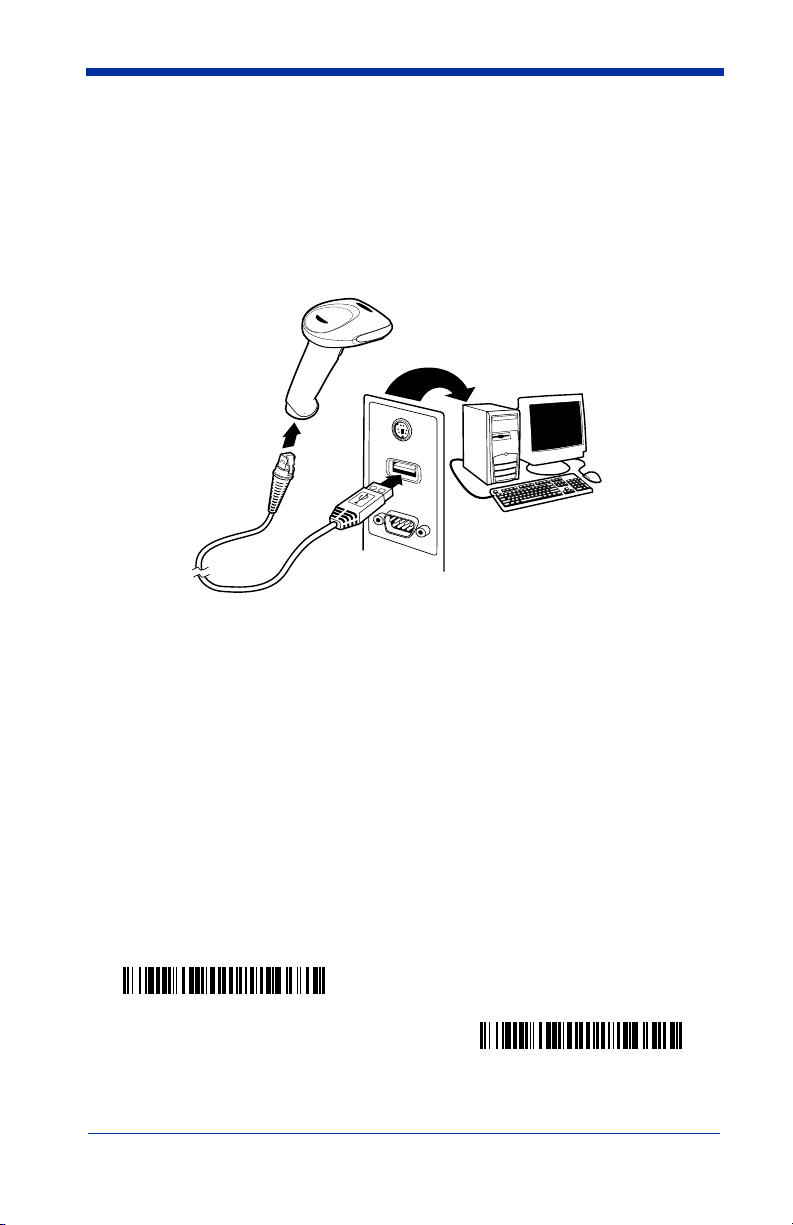
Connecting the Imager with USB
Note: Hand Held Products recommends connecting the imager end of the cable
first and the host end second.
An imager can be connected to the USB port of a computer.
1. Connect the appropriate interface cable to the imager and to the computer.
2. The imager beeps.
3. Verify the imager operation by scanning a bar code from the Sample
Symbols in the back of this manual.
For additional USB programming and technical information, refer to the Hand
Held Products “USB Application Note,” available at www.handheld.com.
USB PC or Macintosh Keyboard
The 3800g imagers are factory programmed for a USB interface. If this is your
interface and you do not need to modify the settings, skip to Chapter 3.
If you programmed the imager for a different terminal interface and you want to
change to a USB Keyboard (PC) or USB Keyboard (Mac), scan one of the
following codes to program the 3800g. Scanning these codes adds a CR and
selects the terminal ID (USB PC Keyboard - 124, USB Macintosh Keyboard -
125).
USB Keyboard (PC)
USB Keyboard (Mac)

3800g User’s Guide 1 - 3
IBM SurePos
Scan one of the following “Plug and Play” codes to program the 3800gX5 for IBM
SurePos (USB Handheld imager) or IBM SurePos (USB Tabletop imager).
Note: After scanning one of these codes, you must power cycle the cash
register.
USB HID
Scan the following code to program the 3800g for USB HID bar code scanners.
Scanning this code changes the terminal ID to 131.
USB Com Port Emulation
Scan the following code to program the 3800g to emulate a regular RS-232-
based Com Port. If you are using a Microsoft® Windows® PC, you will need to
download a driver from the Hand Held Products website (www.handheld.com
).
The driver will use the next available Com Port number. Apple® Macintosh
computers recognize the imager as a USB CDC class device and automatically
uses a class driver. Scanning the code below changes the terminal ID to 130.
Note: No extra configuration (e.g., baud rate) is necessary.
CTS/RTS Emulation
IBM SurePos (USB Handheld Scanner) Interface
IBM SurePos (USB Tabletop Scanner) Interface
USB HID Bar Code Scanner
USB Com Port Emulation
On
* Off

1 - 4 3800g User’s Guide
ACK/NAK Mode
Plug and Play
Plug and Play bar codes provide instant imager set up for commonly used
interfaces.
Note: After you scan one of the codes, power cycle the host terminal to have the
interface in effect.
On
* Off
3800g User’s Guide 1 - 5
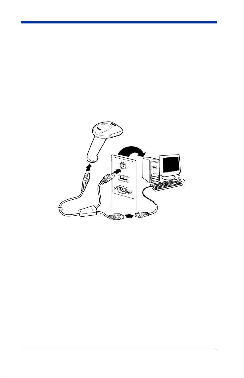
Connecting the Imager When Powered by Host
(Keyboard Wedge)
An imager can be connected between the keyboard and PC as a “keyboard
wedge,” plugged into the serial port or connected to a portable data terminal.
The following is an example of a keyboard wedge connection:
1. Turn off power to the terminal/computer.
2. Disconnect the keyboard cable from the back of the terminal/computer.
3. Connect the appropriate interface cable to the imager and to the terminal/
computer.
4. Turn the terminal/computer power back on.
Note: You will not hear a power-up beep because the 3800g is factory defaulted
to a USB connection. You must scan the IBM PC AT and Compatibles
with CR suffix bar code on page 1-6 to enable keyboard wedge ability.
Verify the imager operation by scanning a bar code from the Sample Symbols in
the back of this manual. The imager beeps once.
Keyboard Wedge Connection
Scanning the bar code below allows operation of the 3800g as a keyboard wedge
interface to an IBM PC AT with a U. S. keyboard.

1 - 6 3800g User’s Guide
If you programmed the imager for a different terminal interface and you want to
change to an IBM PC AT and compatibles keyboard wedge interface, scan the
bar code below.
Note: The following bar code also programs a carriage return (CR) suffix.
Laptop Direct Connect
For most laptops, scanning the Laptop Direct Connect bar code allows
operation of the imager in parallel with the integral keyboard. The following
Laptop Direct Connect bar code selects terminal ID 03, programs a carriage
return (CR) suffix and turns on Emulate External Keyboard (page 2-5).
Connecting the Imager with RS-232 Serial Port
1. Turn off power to the terminal/computer.
2. Connect the appropriate interface cable to the imager.
Note: For the imager to work properly, you must have the correct cable for your
type of terminal/computer.
3. Plug the serial connector into the serial port on your computer. Tighten the
two screws to secure the connector to the port.
IBM PC AT and Compatibles
with CR suffix
Laptop Direct Connect
with CR suffix

3800g User’s Guide 1 - 7
4. Connect the power supply and plug into an outlet.
5. Turn the terminal/computer power back on.
Note: You will not hear a power-up beep because the 3800g is factory defaulted
to a USB connection. You must scan the RS-232 Interface bar code
below to enable RS-232 ability.
All communication parameters between the imager and terminal must match for
correct data transfer through the serial port using RS-232 protocol. Scanning the
RS-232 interface bar code, programs the imager for an RS-232 interface at
38,400 baud, parity–none, 8 data bits, 1 stop bit, and adds a suffix of a CR LF.
Refer to page 2-7 for additional RS-232 configuration settings.
IBM 4683 Ports 5B, 9B, and 17 Interface
Scan one of the following “Plug and Play” codes to program the 3800GX5E for
IBM 4683 Port 5B, 9B, or 17.
Note: After scanning one of these codes, you must power cycle the cash
register.
RS-232 Interface
IBM 4683 Port 5B Interface
IBM 4683 Port 9B HHBCR-1 Interface
IBM 4683 Port 17 Interface
IBM 4683 Port 9B HHBCR-2 Interface
1 - 8 3800g User’s Guide
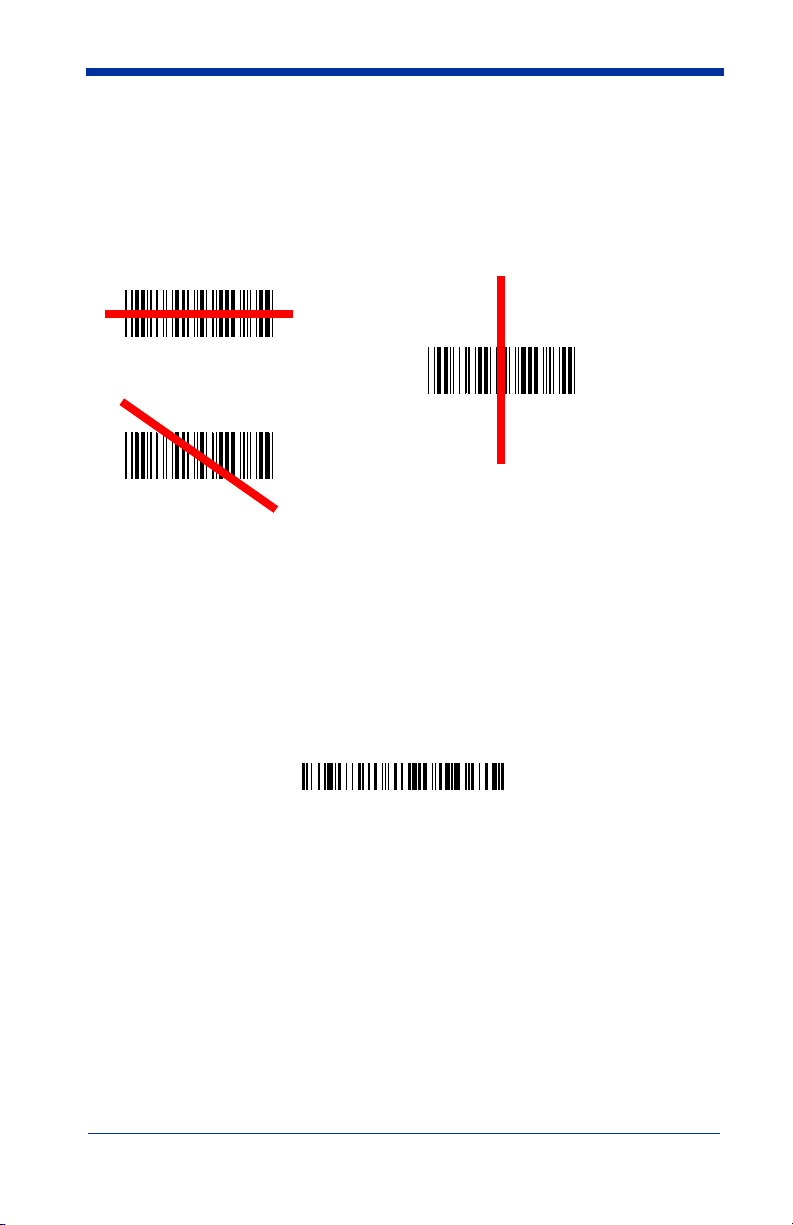
Reading Techniques
The imager has a bright red aiming beam that corresponds to its horizontal field
of view. The aiming beam should be centered horizontally over the bar code; it
will not read if the aiming beam is in any other direction.
The best focus point for reading most code densities is about 5 inches (12.7 cm)
from the unit. To read a single bar code or multiple bar codes (on a page or on
an object), hold the imager at an appropriate distance from the target, pull the
trigger, and center the aiming beam on the bar code.
Resetting the Standard Product Defaults
If you aren’t sure what programming options are in your imager, or you’ve
changed some options and want the factory settings restored, scan the
Standard Product Default Settings
bar code below.
The Menu Commands starting on page 11-5 lists the factory default settings for
each of the commands (indicated by an asterisk (*) on the programming pages).
Good Technique
Bad Technique
Bad Technique
Standard Product Default Settings

3800g User’s Guide 2 - 1
2
Terminal Interfaces
Terminal ID
If your interface is not a standard PC AT, refer to Terminal ID, beginning on page
2-1 and locate the Terminal ID number for your PC. Scan the Terminal ID bar
code below, then scan the numeric bar code(s) from the Programming Chart
inside the back cover of this manual to program the imager for your terminal ID.
Scan Save to save your selection.
For example, an IBM AT terminal has a Terminal ID of 003. You would scan the
Terminal ID bar code, then 0, 0, 3 from the Programming Chart inside the back
cover of this manual, then Save. If you make an error while scanning the digits
(before scanning Save), scan the Discard code on the Programming Chart, scan
the Terminal ID bar code, scan the digits, and the Save code again.
Note: After scanning one of these codes, you must power cycle your computer.
Terminal ID
Save

2 - 2 3800g User’s Guide
Supported Terminals
Terminal Model(s) Terminal ID
DEC VT510, 520, 525 (PC style)
005
DEC VT510, 520, 525 (DEC style
LK411)
104
Esprit 200, 400
005
Heath Zenith PC, AT
003
HP Vectra
003
IBM XT
001
IBM PS/2 25, 30, 77DX2
002
IBM AT, PS/2 30–286, 50, 55SX, 60,
70, 70–061, 70–121, 80
003
IBM 102 key 3151, 3161, 3162, 3163, 3191,
3192, 3194, 3196, 3197, 3471,
3472, 3476, 3477
006
IBM 122 key 3191, 3192, 3471, 3472
007
IBM 122 key 3196, 3197, 3476, 3477, 3486,
3482, 3488
008
IBM 122 key 3180
024
IBM 122 key 3180 data entry keyboard
114
IBM DOS/V 106 key PC & Workstation
102
IBM SurePOS USB Handheld Imager
128
IBM SurePOS USB Tabletop Imager
129
IBM Thinkpad 360 CSE, 340, 750
097
IBM Thinkpad
106
IBM Thinkpad 365, 755CV
003
I/O 122 key 2676D, 2677C, 2677D
008
ITT 9271
007
Lee Data IIS
007
NEC 98XX Series
103
Olivetti M19, M200
001
Olivetti M240, M250, M290, M380,
P500
003
RS-232 TTL
000
Silicon Graphics Indy, Indigoll
005
Telex 88 key 078, 078A, 79, 80, 191, 196,
1191,1192, 1471, 1472, 1476,
1477, 1483
025
Telex 88 key Data Entry Keyboard
112
Telex 102 key 078, 078A, 79, 80, 191, 196,
1191,1192, 1471, 1472, 1476,
1477, 1483
045

3800g User’s Guide 2 - 3
* Factory default setting
Telex 122 key 078, 078A, 79, 80, 191, 196,
1191,1192, 1471, 1472, 1476,
1477, 1482, 1483
046
USB PC Keyboard
124 *
USB Mac Keyboard
125
USB Com Port
130
USB HIDPOS
131
Supported Terminals (Continued)
Ter minal Model(s) Terminal ID

2 - 4 3800g User’s Guide
Keyboard Country
Scan the appropriate country code below to program the keyboard for your
country. As a general rule, the following characters are supported, but need
special care for countries other than the United States:
@ | $ # { } [ ] = / ‘ \ < > ~
* United States
Denmark
France
Germany/Austria
Great Britain
Italy
Norway
Spain
Switzerland
Belgium
Finland

3800g User’s Guide 2 - 5
Please refer to Hand Held Products website ( www.handheld.com) for complete
keyboard country support information and applicable interfaces. If you need to
program a keyboard for a country other than one listed above, scan the Program
Keyboard Country bar code below, then scan the numeric bar code(s) for the
appropriate country from the inside back cover, then the Save bar code.
Keyboard Style
This programs keyboard styles, such as Caps Lock and Shift Lock.
Default =
Regular.
Regular
is used when you normally have the Caps Lock key off.
Caps Lock
is used when you normally have the Caps Lock key on.
Shift Lock
is used when you normally have the Shift Lock key on (not common
to U.S. keyboards).
Automatic Caps Lock
is used if you change the Caps Lock key on and off. The
software tracks and reflects if you have Caps Lock on or off (AT and PS/2 only).
This selection can only be used with systems that have an LED which notes the
Caps Lock status.
Autocaps via NumLock
bar code should be scanned in countries (e.g.,
Germany, France) where the Caps Lock key cannot be used to toggle Caps
Lock. The NumLock option works similarly to the regular Auotcaps, but uses the
NumLock key to retrieve the current state of the Caps Lock.
Program Keyboard Country
* Regular
Caps Lock
Shift Lock
Automatic Caps Lock
Autocaps via NumLock

2 - 6 3800g User’s Guide
Emulate External Keyboard
should be scanned if you do not have an external
keyboard (IBM AT or equivalent).
Note: After scanning the Emulate External Keyboard bar code, you must power
cycle your computer.
Keyboard Modifiers
This modifies special keyboard features, such as CTRL+ ASCII codes and Turbo
Mode.
Control + ASCII Mode On:
The imager sends key combinations for ASCII
control characters for values 00-1F. Refer to Keyboard Function
Relationships, page 8-1 for CTRL+ ASCII Values.
Default = Off
Turbo Mode:
The imager sends characters to a terminal faster. If the terminal
drops characters, do not use Turbo Mode.
Default = Off
Numeric Keypad Mode:
Sends numeric characters as if entered from a
numeric keypad.
Default = Off
Emulate External Keyboard
Control + ASCII Mode On
* Control + ASCII Mode Off
Turbo Mode On
* Turbo Mode Off
Numeric Keypad Mode On
* Numeric Keypad Mode Off

3800g User’s Guide 2 - 7
Automatic Direct Connect Mode:
This selection can be used if you have an
IBM AT style terminal and the system is dropping characters.
Default = Off
RS-232 Baud Rate
Baud Rate sends the data from the imager to the terminal at the specified rate.
The host terminal must be set for the same baud rate as the imager.
Default = 115,200
.
Automatic Direct
Connect Mode On
* Automatic Direct Connect
Mode Off
300
2400
600
1200
4800
38400
9600
19200
* 115,200
57,600

2 - 8 3800g User’s Guide
RS-232 Word Length: Data Bits, Stop Bits, and Parity
Data Bits
sets the word length at 7 or 8 bits of data per character. If an
application requires only ASCII Hex characters 0 through 7F decimal (text, digits,
and punctuation), select 7 data bits. For applications which require use of the full
ASCII set, select 8 data bits per character.
Default = 8.
Stop Bits
sets the stop bits at 1 or 2.
Default = 1.
Parity
provides a means of checking character bit patterns for validity.
Default = None.
7 Data, 1 Stop, Parity Even
7 Data, 1 Stop, Parity None
7 Data, 1 Stop, Parity Odd
7 Data, 2 Stop, Parity Odd
7 Data, 2 Stop, Parity Even
7 Data, 2 Stop Parity None
* 8 Data, 1 Stop, Parity None
8 Data, 1 Stop, Parity Even
8 Data, 1 Stop, Parity Odd
 Loading...