

Page 1

Supported Equipment Manual
for the 7400 and 9500 Computers Manufactured by Hand Held Products
Page 2

Copyright © 1996 - 2006 by Connect, Inc.
All rights reserved. This document may not be reproduced in full or in part, in any form, without
prior written permission of Connect Inc., 1701 Quincy Avenue, Suites 5 & 6, Naperville, IL
60540.
Connect, Inc. makes no representation or warranties with respect to the contents of this
document and specifically disclaims any implied warranties of merchantability or fitness
for any particular purpose. Further, Connect, Inc. reserves the right to revise this
publication and to make changes to it from time to time without obligation to notify any
person or organization of such revision or changes.
Trademarks
PowerNet OpenAir™, OpenAir Linux™, OpenAir Windows™, OpenAir 400™,
PowerNet TwinClient™, and PowerNet AirLinc™ are trademarks of Connect, Inc.
Other product names mentioned in this manual may be trademarks or registered
trademarks of their respective companies and are hereby acknowledged.
Production
This manual was written, edited, and produced by:
Connect, Inc.
1701 Quincy Avenue,
Suites 5 & 6
Naperville, IL 60540
www.connectrf.com
Printed in the U.S.A.
Please let us know about any errors in this document at:
http://207.241.78.223/isoxpert/calltrak.nsf/WebTracking?OpenForm
Page 3

Chapter 1 • Introduction…………............................................................................................1-1
Descriptions………………............................................................................................1-1
Pictures………..…………………...................................................................................1-2
Setup Requirements…….............................................................................................1-3
Accessories……………….............................................................................................1-3
Bios…………………………............................................................................................1-3
Release Notes…………….............................................................................................1-4
Chapter 2 • Terminal Setup.....................................................................................................2-1
Downloading from the WEB........................................................................................2-1
Running Setup from a Download File ........................................................................2-1
Installation…………………...........................................................................................2-2
Running the Manager…………....................................................................................2-4
Quick Start…………………...........................................................................................2-5
Configuring the Manager....................................................................................2-5
Configuring the Terminal for Download............................................................2-12
Power, Radio, and Signal Icons .......................................................................2-12
Standard Setup…………….........................................................................................2-13
Setup Using Twin Client Manager....................................................................2-13
Terminal Setup Using Twin Client Menus ........................................................2-19
Authorizing PowerNet....................................................................................... 2-21
Software Management……........................................................................................2-27
Airloader Auto-Configuration ............................................................................2-27
Mobile Device Manager (MDM) Features.........................................................2-33
Sending Configuration Files to the 7400/9500 Terminal ..................................2-45
Sending Program Files to the 7400/9500 Terminal..........................................2-51
Chapter 3 • Keypad Configuration..........................................................................................3-1
Dolphin 7400 43-key Terminal….................................................................................3-1
Keypad Figures ..................................................................................................3-1
Keypad Table .....................................................................................................3-5
Dolphin 7400 56-key Terminal….................................................................................3-8
Keypad Figures ..................................................................................................3-8
Keypad Table ...................................................................................................3-12
Dolphin 7400 35-key Terminal…...............................................................................3-15
Keypad Figures ................................................................................................3-15
Keypad Table ...................................................................................................3-19
Supported Equipment Manual
•
January, 2006 iii
Page 4

Dolphin 9500 43-key Terminal ..............................................................................................3-22
Keypad Figures ............................................................................................................ 3-22
Keypad Table ............................................................................................................... 3-26
Dolphin 9500 56-key Terminal ..............................................................................................3-29
Keypad Figures ............................................................................................................ 3-29
Keypad Table ............................................................................................................... 3-33
Dolphin 9500 35-key Terminal ..............................................................................................3-36
Keypad Figures ............................................................................................................ 3-36
Keypad Table ............................................................................................................... 3-40
Chapter 4 • Error Message Resolution Guide .......................................................................4-1
iv Supported Equipment Manual • January, 2006
Page 5

Descriptions
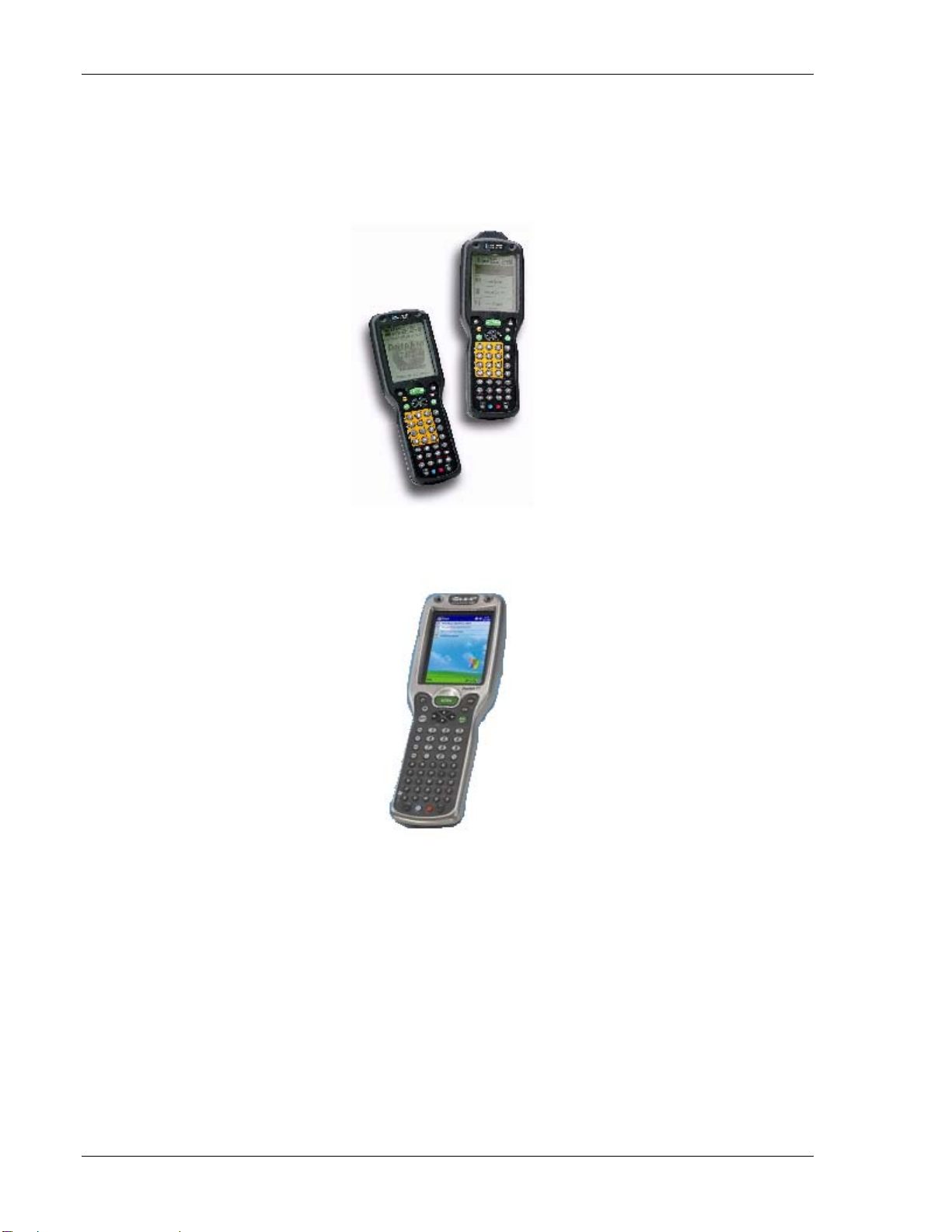
7400
The Dolphin 7400’s case houses a 206MHz RISC processor and Windows CE
operating system that is programmable with standard programming tools, like Microsoft
Windows CE
eMbedded Visual Basic
The Dolphin 7400 computer is known for its ergonomic shape, lightweight, and singlehanded data collection features. It is designed to withstand repeated five-foot drops onto
concrete, and resists extreme temperatures, humidity levels, and dust conditions.
Chapter 1 • Introduction
TM
TM
eMbedded Visual Tools, which includes embedded Visual C/C++® and
®
.
9500
The Dolphin 9500 mobile computer is equipped with all the features needed for mobile
applications, including the Intel
Mobile, or Windows Mobile 2
technology, and WLAN, WWAN and/or WPAN support.
This wireless mobile computer has a lightweight and ergonomic design, a large ¼ VGA
display, and multiple keyboard options. The Dolphin 9500 is constructed to withstand
harsh environments and rough treatment.
For more information, visit
®
X-Scale processor and the Pocket PC, Windows
nd
Edition operating system platform, lithium-ion battery
http://www.handheld.com/Site.aspx/na/en/home/.
Supported Equipment Manual
•
January, 2006
1-1
Page 6
Introduction
Pictures
7400
9500
1-2
Supported Equipment Manual • January, 2006
Page 7

Setup Requirements
Setup Re
Accesso i
quirements
Installation of PowerNet Twin Client requires, at a minimum, the following:
•
• 32 MB of RAM
• 10 MB of free hard disk space available
•
• for the 9500: Microsoft Windows Pocket PC or Windows Mobile
r es
The following accessories are available to use with the Dolphin terminals:
•
•
•
A Pentium-class processor
for the 7400: Microsoft Windows Pocket PC or Windows CE
TM
Dolphin HomeBase
includes power adapter
Dolphin Quad Battery Charger: Charges four batteries in under three hours and
conditions in under eigh
Dolphin HomeBaseTM Power Adapter: Replacement power adapter for Dolphin
HomeBase
Failure to do so may result in improper op
TM
Use only power adapters approved for use with Hand Held Products.
:
Dolphin terminal charging and communication station,
t hours
eration or damage to the unit
.
Bios
•
NiMH Battery Pack: Nickel Metal Hydride (NiMH) 2700mAh rechargeable b
for the Dolphin
• RS-232 Serial Cable: Allows the
file transfer or to connect the Dolphin terminal using the terminal’s serial RS-232
interface
Dolphin to connect to other computer systems for
attery
Version of BIOS
The version of BIOS on a 7400 terminal is 3.0. There is no BIOS on a 9500 terminal.
Finding the Ve
The version of BIOS will appear on a 7400 terminal screen when the terminal i
rebooted. For rebooting instructions, see Cold Booting the Terminal in the Configuring
the Terminal for Download section.
rsion of BIOS
s
Supported Equipment Manual • January, 2006 1-3
Page 8

Introduction
Release Not
10/26/
The following describes how to disable the native scanner support built into TwinClient
for the Hand Held Products CE terminals. The most common use of this would be to
allow you to use the Hand
built into TwinClient.
Note:
The reason this happens is that data from the Scan Wedge is "inserted" into the keyboard
buffer. To TwinClient this "scanned" data ed data and it will not execute
an
y of the scan features.
es
2004
Held Products "Scan Wedge" instead of the scanner support
Using this method will cause the following scan features not to work in
TwinClient:
Scanner Send Key
Scanner Decoder Control
Scan Data Editing
Scan Data Mapping
Scanner Striping
Scanner Length Check
Scanner Truncation
Scan Spanning
Scan Ahe
Scanner Binary 128 option
ad
looks like key
Th
e attached DLL at
rsion of the Scan DLL for the Hand Held Products terminals that does n
ve ot open or use
http://www.connectrf.com/Documents/GenericScan.zip is a speci
al
the Scan API in any way. If you "replace" this DLL, with the one that is shipped, it will
all any version of TwinClient for Hand Held Products CE devices.
ow you to modify
To do this you will need to remove the standard scan DLL from the terminal and modify
Tw
inClient to use this modified DLL instead.
1. If the term
"H740Scan.dll".
You can use the "explore" option of Active Sync to do this. Pleas
inal is already loaded, please remove the file on the terminal titled:
e check and delete all
occurrences of this file on the terminal. Normally there will be two; one in RAM and
one in flash.
. On the Twin Client Manager PC, find and edit the file named
2
rffiles.txt. You will
normally find this file in:
C:\PowerNet\TwinClient\Terminal\rfilese.txt
Using a text editor, search this file for; H740Scan.dll and comment out the line by
putting a # in front of it and adding the
# H740Scan.dll
GenericScan.dll
GenericScan.dll right below it.
1-4
Supported Equipment Manual • January, 2006
Page 9

Release Notes
3. Do a program load and test by ou did this right, the scan
trigger WILL NO
T turn on the scan beam.
hitting the Scan Trigger. If y
01-31-2005
Release 7.5.1 solves a problem on 95xx's where the default printer may not be COM1.
The printer on the 95xx's has been changed from Default to Com1.
Supported Equipment Manual • January, 2006 1-5
Page 10

Introduction
This page is intentionally blank.
1-6
Supported Equipment Manual • January, 2006
Page 11
Chapter 2 • Terminal Setup
Downloading from the WEB
The PowerNet Twin Client software package can be downloaded from the Connect web
http://www.connectrf.com. Click on Partner Services and then click on Software
site at
Downloads. Select the file named PowerNet Twin Client for Hand Held Products.
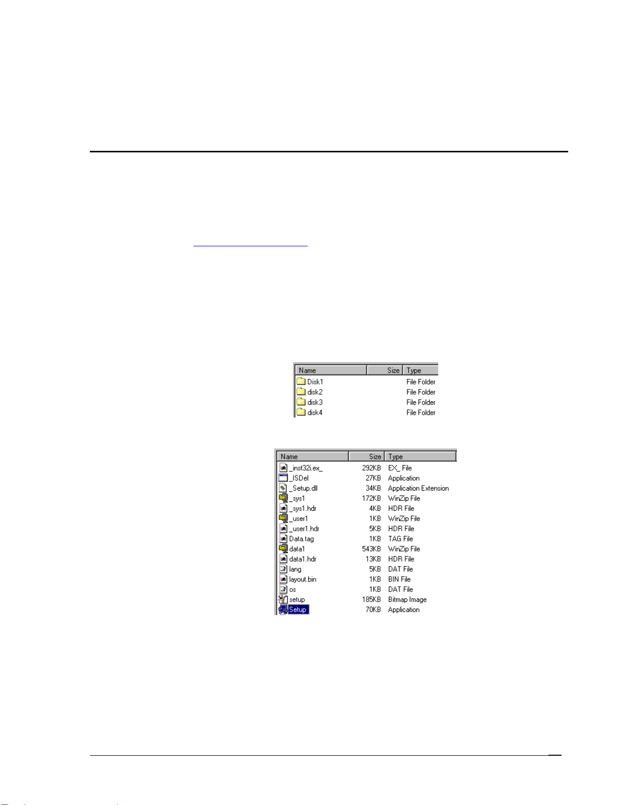
Running Setup from a Download File
The downloaded file is a compressed archive. After extraction using a utility such as
WinZip or PKWARE, folders are created on the hard disk as shown in the following
figure.
Click on the
Click on the
for further instructions.
Disk1 folder to view the files as shown in the following figure.
Setup application and proceed to the following section entitled Installation
Supported Equipment Manual
•
January, 2006
2-1
Page 12
Terminal Setup
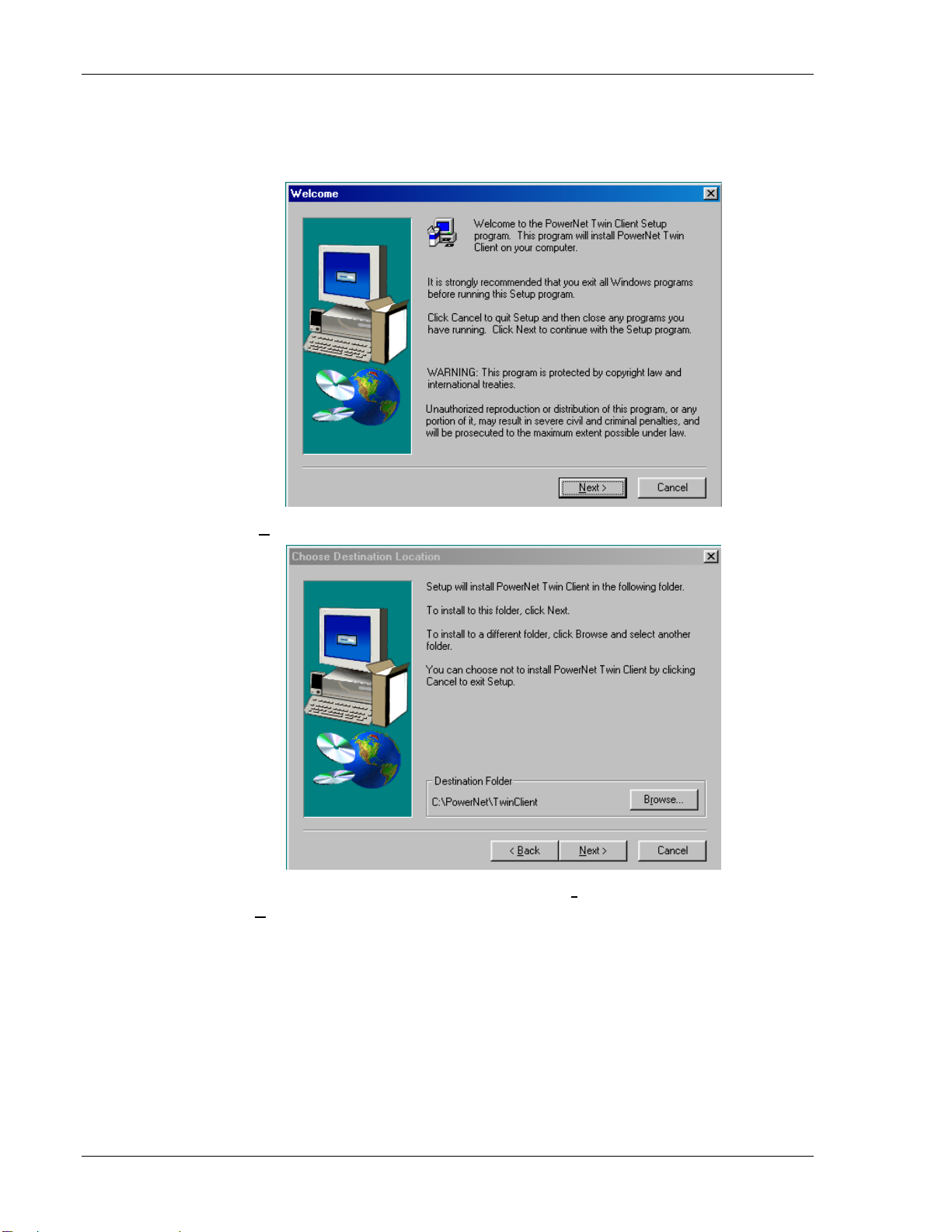
Installati
on
The InstallShield wizard runs and presents the following screen.
Click on
Next to begin the installation process.
To change the default Destination Location, click on
click on
2-2 Supported Equipment Manual • January, 2006
Next.
Browse and select a location. Then
Page 13

Terminal Setup
The default folder is PowerNet. This default may be changed either by selecting an
existing progr
am group or by typing in a new name at the prompt. Then click on
N
Wh t alize the Twin Client
en he installation is complete, reboot the system to initi
software.
ext.
a. To reboot the system immediately, click on
b. To reboot later, cl
ick on the option to restart the computer later, and click on
Finish.
Finish.
Supported Equipment Manual • January, 2006 2-3
Page 14
Terminal Setup
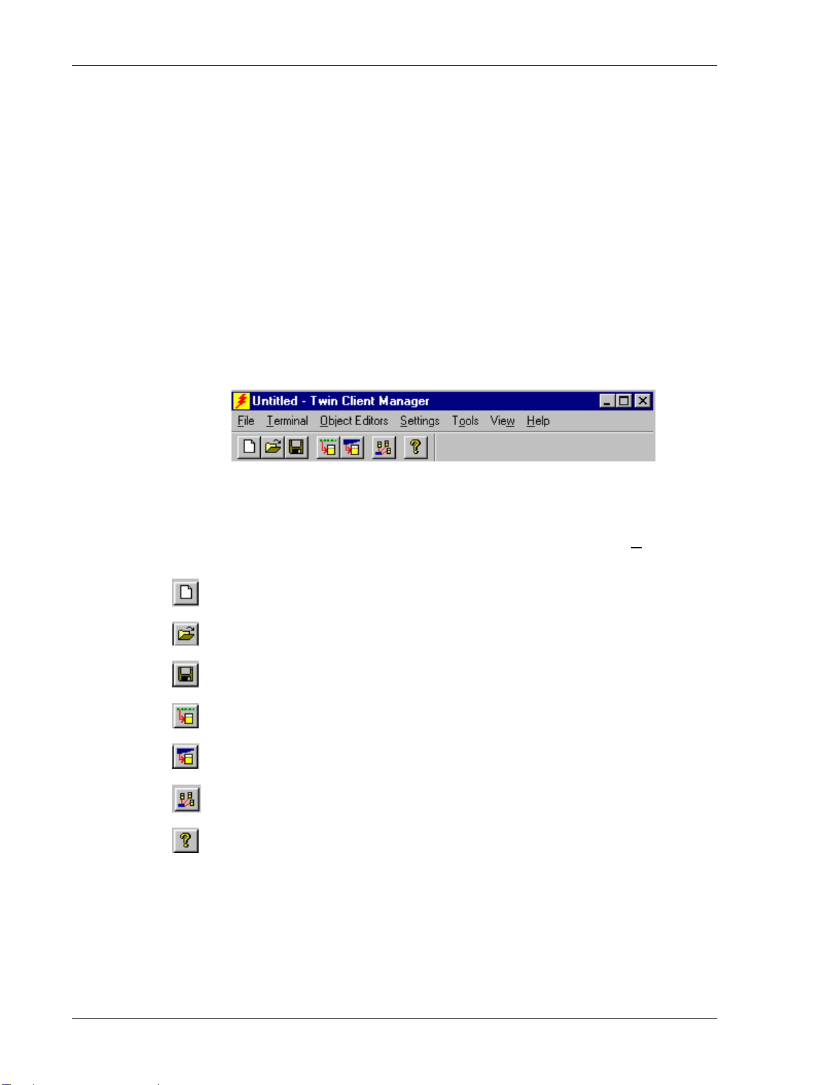
Running the
The PowerNet Twin Client Manager is the utility that manages the terminal software and
configurations.
Select
Client Manager screen appears as shown in the following figure. This is the
administrator's main screen, and all functions are accessed from its menu bar, tool
tabs.
Menu Bar
The menu bar provides
manage their software.
Toolbar
Found under the menu bar, the toolbar provides shortcuts to major features. The toolbar
can be turned on or off by changing the Toolbar parameter found on the
shortcuts available from the toolbar are as follows:
Manager
Start, Programs, PowerNet, and Twin Client Manager. The PowerNet Twin
bar, and
access to the functions used to configure the terminals and
View menu. The
Create a new terminal configuration.
Open an existing terminal configuration.
Save the current terminal configuration.
Download the configuration to the terminal.
Download software to the terminal.
Configure terminals automatically over the wireless network.
View the PowerNet Twin Client Manager version.
The PowerNet Twin Client Manager is now successfully installed and ready for use. The
next section provides detailed instructions for quickly configuring the terminal and
starting a Telnet session.
2-4 Supported Equipment Manual • January, 2006
Page 15

Terminal Setup
Quick St
art
This section describes how to prepare the Twin Client Manager an
Products terminal for a Telnet session with the host. Following an
the terminal software and configuration are m naged automatically over the wireless
network.
Note: Hand Held Products terminals are normally delivered with Hand Held Products
files pre-installed. However, if the terminal does not have those files installed,
refer to instructions at the end of the
proceeding.
a
Software Management section before
Configuring the Manager
The first step is to configure the Twin Client Manager to meet site-specific requirements,
and then prepare it for the automatic management of the terminal software and IP
addresses. This simple procedure will require only a few minutes to complete.
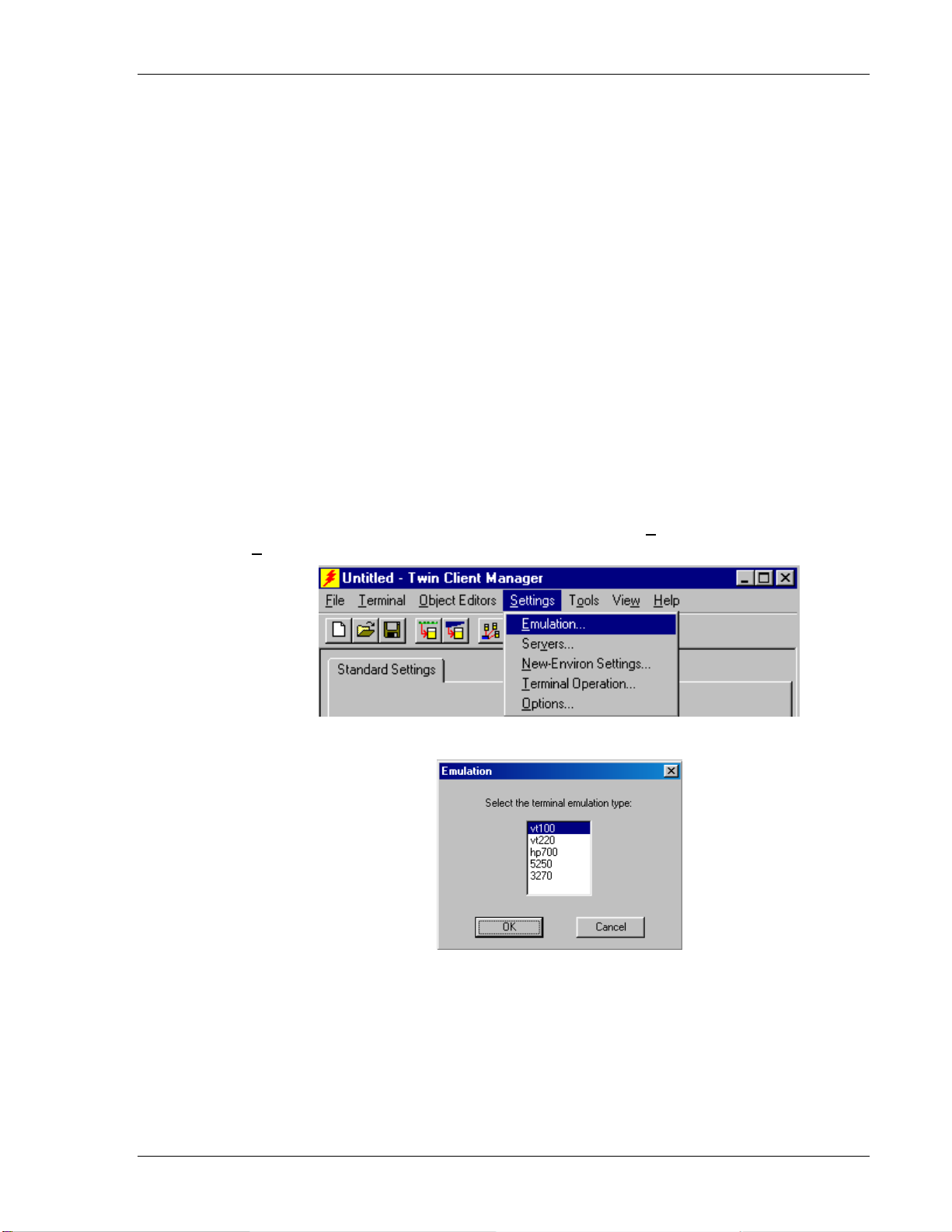
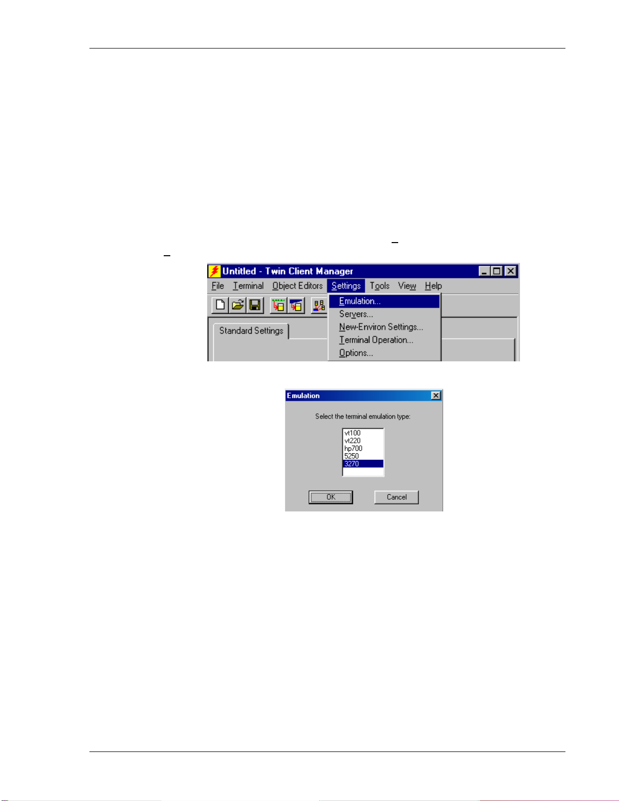
Setting the Emulation
Click on Start, Programs, PowerNet, and Twin Client Manager. Select the S
menu as shown below.
d the Hand Held
initial serial download,
ettings
Click on
Emulation, select the desired emulation, and click on OK.
Supported Equipment Manual • January, 2006 2-5
Page 16
Terminal Setup
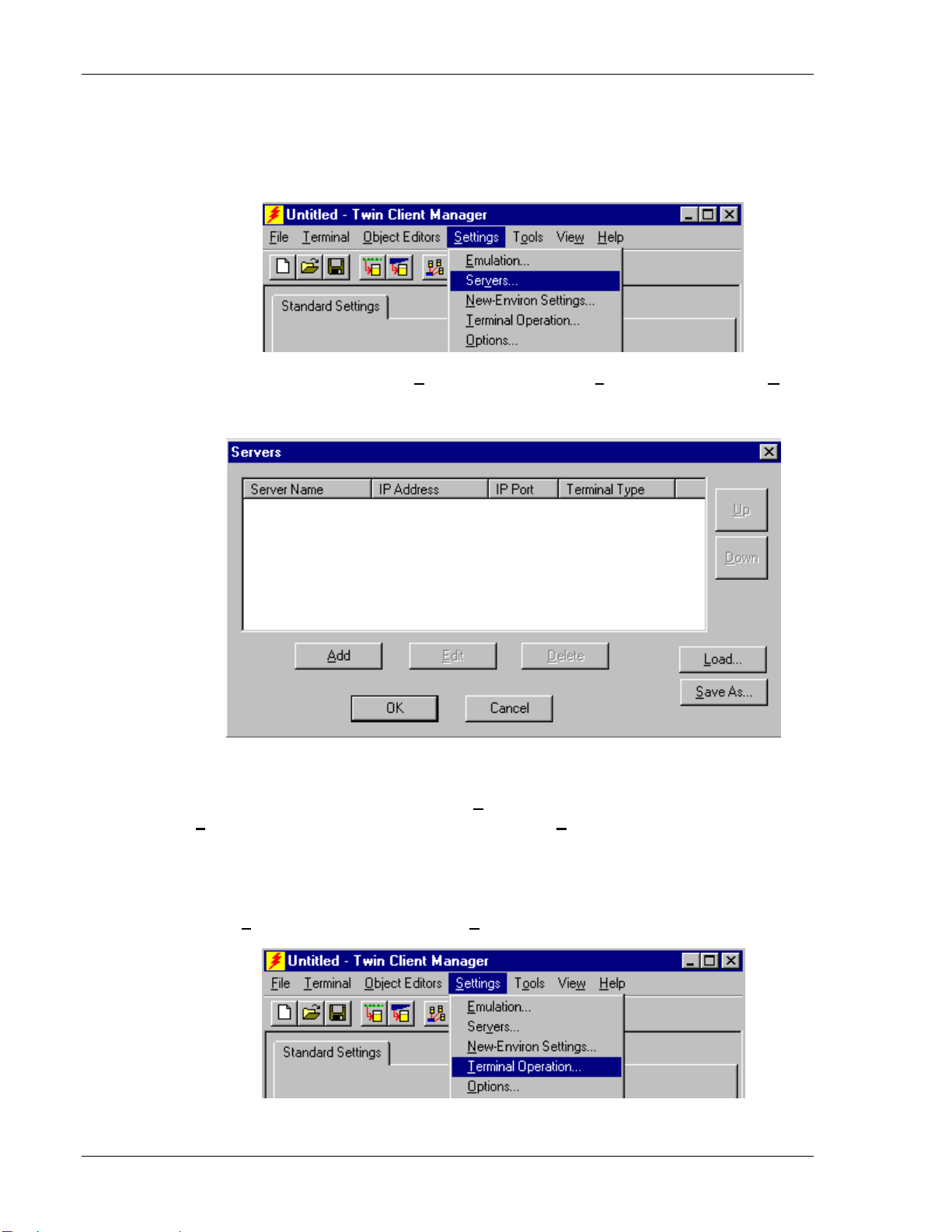
Setting the Servers
The Servers are the Telnet host systems the terminals will access.
To set these addresses from the
Settings menu, click on Servers and then click on Add.
Enter the name of each server, its IP address and IP port (normally 23 for Telnet servers),
and emulation type. Then click on
OK.
Repeat this step for each Telnet server the terminals are required to access. If an error is
made in the name, IP address, IP port number, or terminal emulation type, click on the
E
line that is in error and then click on the
Load button if you want to load an .svr file. Use the Save As button if you want to save
dit button to make the corrections. Use the
your file as an .svr file.
Setting Terminal Operations
Terminal Operation from under Settings in Twin Client Manager.
Select
2-6 Supported Equipment Manual • January, 2006
Page 17

Terminal Setup
The option of Run Airloader on terminal can be selected. The Windows CE options of
Run application at startup and Hide task bar can be selected. Also, there is a CE
Use GUI menus and screens
option
that makes the terminal program act more
"Windows-like".
The
Code page setting determines the Windows font code page that will be used on the
terminal. The default is zero, which means th the terminal will use the standard Unicode
code page. This option is necessary to turn on character sets for foreign languages. Fo
at
r
more information on code pages, see the document entitled “Code Pages” at
http://www.connectrf.com/faq.htm.
Enable aggressive
optimizing how the imager reads barcodes.
option to enable it
Enabling
centering beam during imaging means that when the imager is on, a darker
linear decoding and Linear search range have to do with
Check the box in front of the linear decoding
and use the search range scroll box to make a selection from 1 to 6.
red "line" appears in the middle of the scanning area to help in positioning the barcode.
Check the box in front of this option to enable it.
The Timeout for laser aiming beam option applies only to terminals with long-range
laser scanners, not imagers. When the user first pulls the trigger, the scanner emits a
bright dot, which is used to aim the scanner at a barcode that is far away. This timeout is
how long the dot stays on before the scanning beam appears. Enter in the box the number
of seconds after which the laser aiming beam will time out.
Click on OK after entering information.
Supported Equipment Manual • January, 2006 2-7
Page 18
Terminal Setup
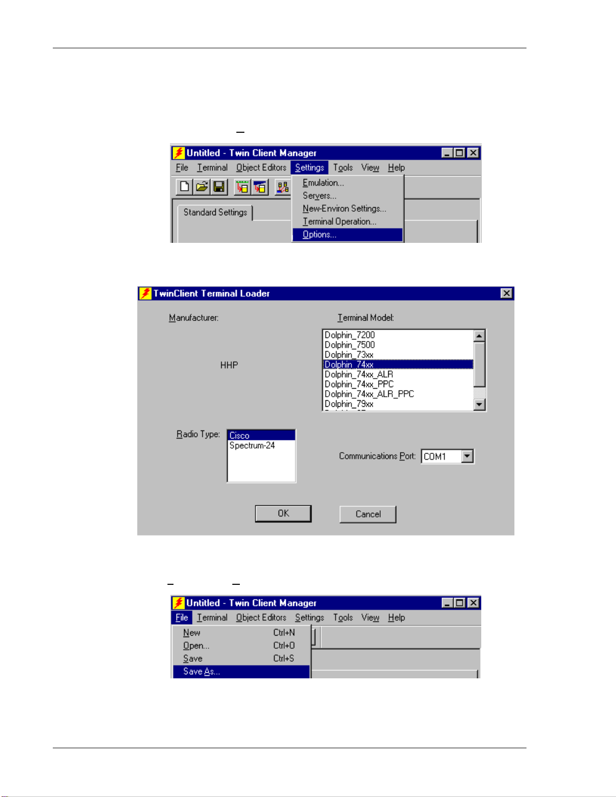
Setting Terminal Model and COM Port
To select a specific Hand Held Products terminal model, radio type, or COM port
assignment, click on the
To maintain compatibility with existing Hand Held Products Telnet client keyboard
layouts, a specific terminal model must be selected from the Terminal Model window.
Options menu as shown.
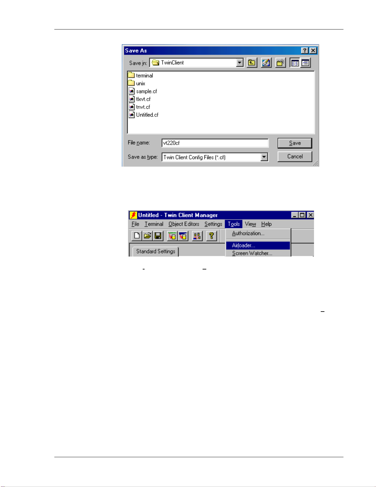
Saving the Configuration
Click on File and Save As. Enter a name for this configuration.
For the purposes of this example, the name is
2-8 Supported Equipment Manual • January, 2006
vt220.
Page 19
Terminal Setup
Setting Airloader Auto-Configuration
The configuration download and IP address assignment for each terminal will take place
automatically by setting the Airloader Auto-Configuration options.
Click on the
Note: If the Airloader Auto-Configuration window does not display the options, click on
If multiple network adapters are installed on the PC, ensure that the d
adapter is selected. The adapter selection can be changed by
Airloader option in the Tools menu.
Advanced<< button.
the
esired network
clicking on the
Chang
e
button.
Supported Equipment Manual • January, 2006 2-9
Page 20
Terminal Setup
This powerful s nt tool is described in detail in Airloader AutoConfiguration
terminal conf
that all of
To assign terminal IP addresses automaticall the
boxes as show
From and To boxes as shown in the following figure.
in the
oftware manageme
. For now, it is sufficient simp
igu o
ration and IP address, both
the ch h
eck boxes are checked as s
n he
above. Then click on t
Ad nd enter the desired range
ly to use it for assignment of the initial
f which can be easily changed later. Ensure
own above.
y over the wireless network, check all of
dresses button a
After setting the address range, click on
screen and then click on the box next t
2-10 Supported Equipment Manual • January, 2006
OK to return to the A loader A
Terminal/Gro p Manag r.
o
u e
ir uto-Configuration
Page 21
Terminal Setup
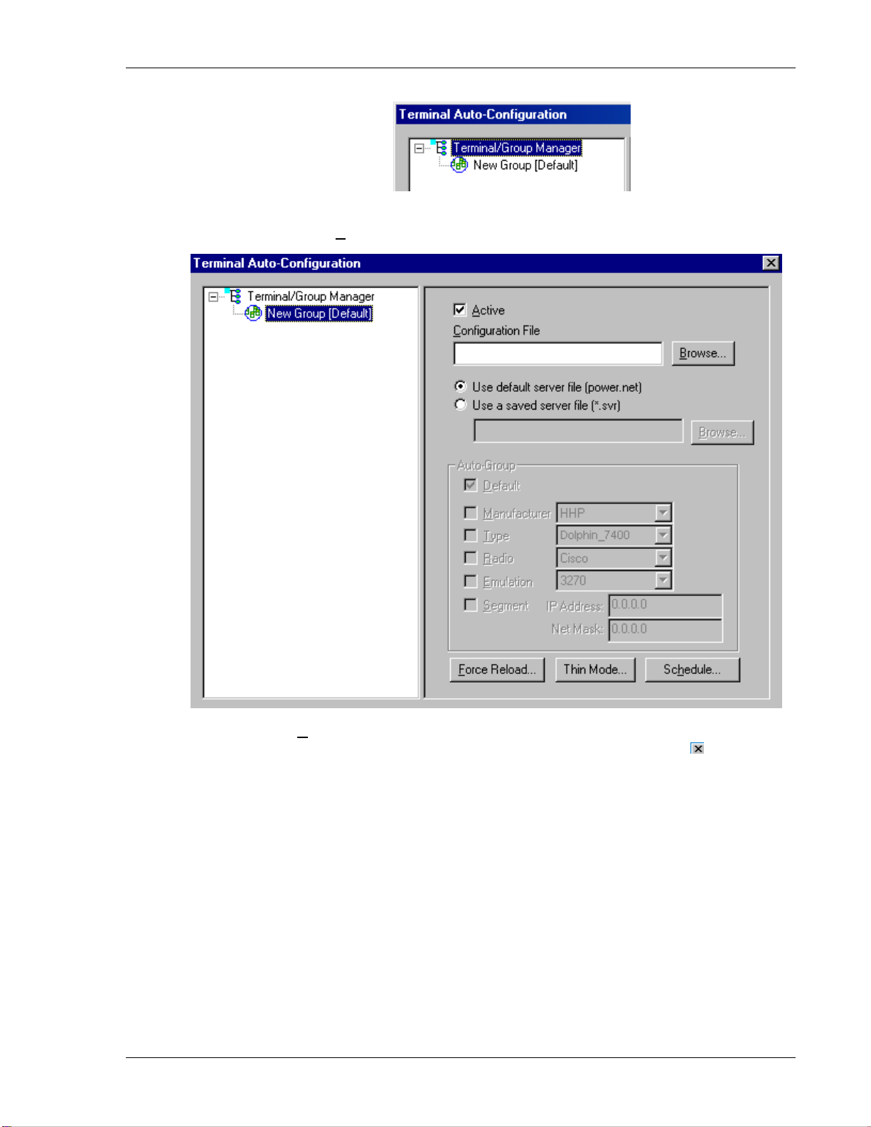
The display expands to show the default terminal group. Next, click on the
icon and use the
Browse button to select the configuration file saved earlier.
New Group
Check the
addresses, software, and configuration files to the terminals. Click on the
Active box, and the system is now configured to automatically download IP
box in the
upper right corner to return to the main menu.
Note: The software does not need to be authorized now. It can be authorized later, after a
Telnet session has been established. The procedure is described in the section
entitled Authorizing PowerNet.
Supported Equipment Manual • January, 2006 2-11
Page 22

Terminal Setup
Configuring the Terminal for Download
The 7400 and 9500 terminals are configured for download using ActiveSync, as
described in the Sending Configuration Files to the 7400/9500 Terminal section.
The following is the cold boot sequence that each requires.
Cold Booting the Terminal
Following Power OFF, press the ESC and CTRL keys for several seconds, then release.
Troubleshooting
Error
Indication
No AirLoad
Manager
Found
Manager not
Active
Possible Cause Corrective Action
AirLoad Manager not
active, or not installed on
the LAN segment
Ensure that PC with Twin Client Manager is
on same segment and that PC is operating. If
PC is not on same segment, enter address of
PC in response to the terminal prompt.
Previously identified
Same as above.
AirLoad Manager is no
longer found.
After taking the corrective action, the terminal must be cold booted. A successful
n and download is shown by the Twin Client main menu below. wireless connectio
Twin Client
© 1991-2006, Connect, Inc.
Keypress To Continue
Not
e: The date of 2006 is updated on the terminal at the time of a new release.
The term stem.
Po
inal is now ready to establish a Telnet session with the host sy
wer, Radio, and Signal Icons
The following icons are found at the lower left corner of the Windows-based*
term
inal screen.
he
T power status icons indicate a wall outlet power source ( ) or the
remaining battery power level (low =
radio association icons indicate if terminal is connected to the radio
The
icon(darker
= connected, lighter icon = not connected).
, moderate = , high = ).
The link reception icons indicate signal strength
(low =
, moderate = , high = ).
To utilize these icons, select Settings, and then Terminal Operation.
Click in the Use GUI menus and screens check box, and click on OK.
Then select
* for Pocket PC 2003 and later, and Windows CE 4.2 and later
Terminal, and Send Configuration Files to Terminal.
2-12 Supported Equipment Manual • January, 2006
Page 23
Terminal Setup
Standard Setup
The default terminal setup is sufficient for most installations. However, to meet sitespecific requirements, it may be necessary to customize terminal operation. The standard
setup options simplify this process a
• Using the
• Using the Twin Client terminal menu system.
Twin Client Manager.
nd can be modified by the following methods:
This section describes how
systems to set up the terminal. Also described are the methods for authorizing the
terminal software.
to use the Twin Client Manager and the terminal menu
Setup Using Twin Client Manager
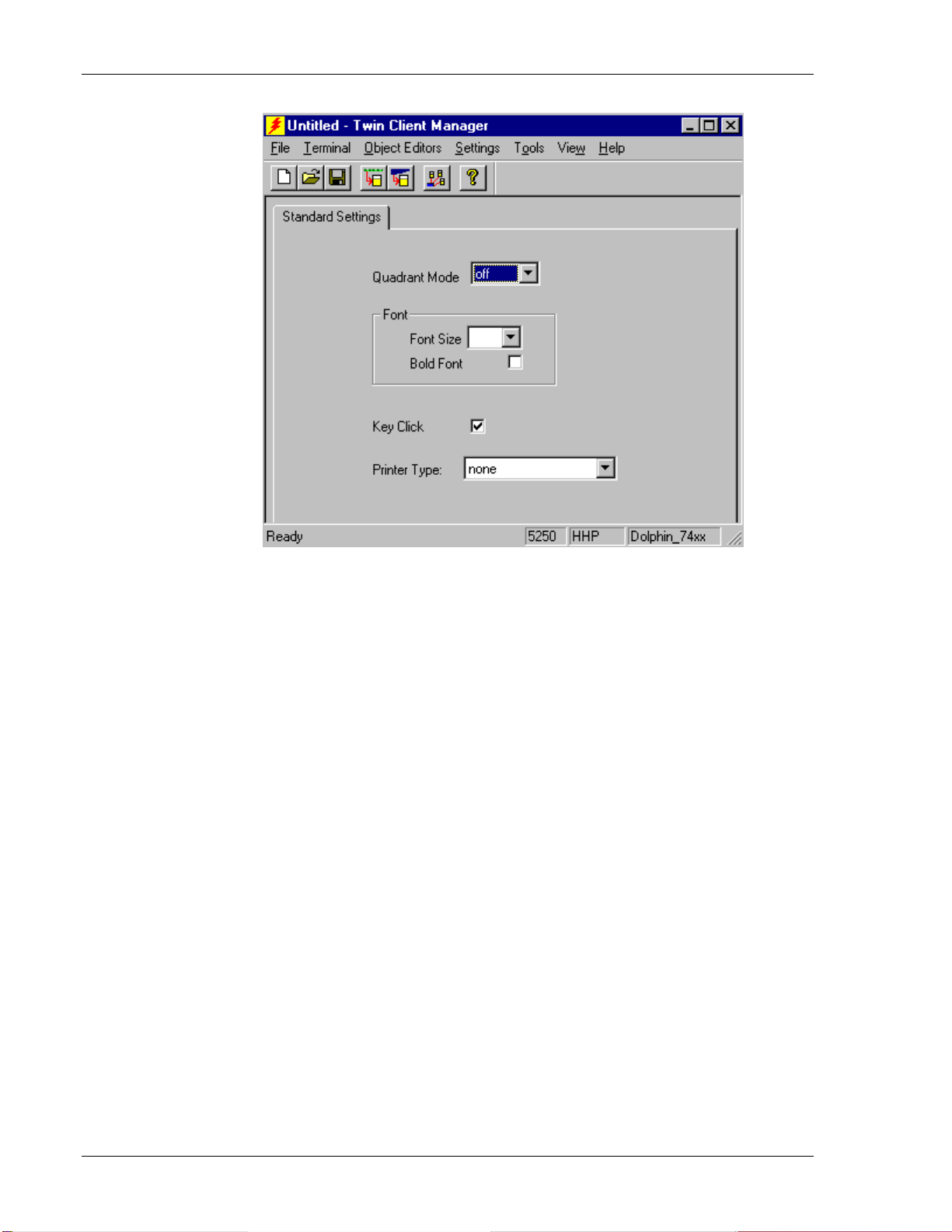
The Twin Client Manager provides a Standard Settings tab for automatic setup of the
terminals. Choose
according to the emulation selected, each of which i
VT and HP Settings
Select the VT and HP emulation setup by clicking on the S
Emulation menu, as shown below.
Then click on the VT100, VT220, or HP700 selection, as shown below.
Standard under the View menu. The options within this tab vary
s described below.
ettings menu and then the
k on OK after the selection is made, and return to the main Twin Client Manager Clic
menu. The standard settings tab will now reflect the settings for VT/HP emulation.
Supported Equipment Manual • January, 2006 2-13
Page 24

Terminal Setup
Quadrant Mode
This scrolling list option defines the rules by which the terminal display is positioned in
the larger host display. As defined by Twin Client, quadrants are fixed position
"windows" in the host display, and the terminal display is located on whatever quadrant
contains the current cursor position.
Off disables quadrant processing and Twin Client simply centers the current host
input field in the terminal display.
On enables quadrant processing. However, inpu
boundaries result in a shift to the left in o er to locate as much of the current input
rd
t fields that cross quadrant
field on the terminal display.
Soft always positions on a quadrant boundary regardless of input field boundaries
.
Viewing keys are enabled.
Hard is the same as Soft except the viewing keys are disabled.
Lock locks the terminal display origin (upper left corner) to fixed row and column
(x,y) coordinates in the host display. The coordinates are zero-based.
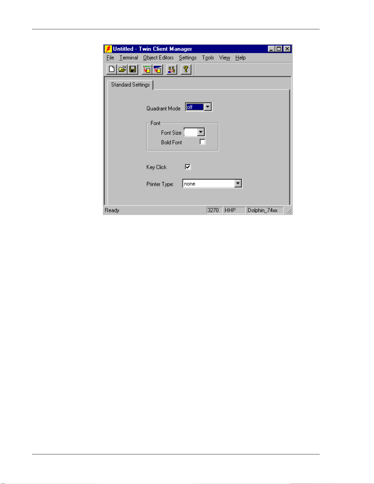
Font
The Font Size scroll box allows you to choose the font size and the Bold Font check box
enables (checked) or disables (unchecked) the display of characters in bold font.
2-14 Supported Equipment Manual • January, 2006
Page 25
Terminal Setup
Key Click
This check box enables (checked) or disables (unchecked) audible key clicks from the
terminal, provided that the manufacturer supports the control of terminal key click sound.
The default value is
Printer Type
on (checked).
This scrolling list selects the attached printer type. The default value is none, indicating
that no printer is attached.
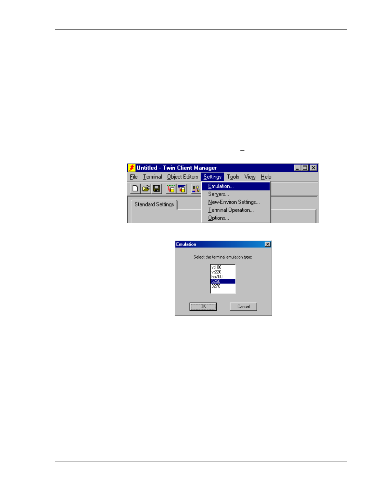
5250 Settings
Select the 5250 emulation setup by clicking on the Settings menu and then the
Emulation menu, as shown below.
Then click on the 5250 selection, as shown below.
Click on OK after the selection is made, and return to the main Twin Client Manager
menu. The standard settings tab will now reflect the settings for 5250 emulation.
Supported Equipment Manual • January, 2006 2-15
Page 26
Terminal Setup
Quadrant Mode
This scrolling list opt
the larger host display
"windows" in the h
contains the curren
Off disables quadr
input field in the t
On enables quadrant processing. However, input fields that cross quadrant
boundaries result in
ion defines the rules by which the terminal display is positioned in
. As defined by Twin Client, quadrants are fixed position
ost display, and the terminal display is located on whatever quadrant
t cursor position.
ant processing and Twin Client simply centers the current host
erminal display.
a shift to the left in order to locate as much of the current input
field on the terminal display.
Soft always positions on a quadrant boundary reg
Viewing keys are
Hard is the sam
Lock locks the te
(x,y) co
Font
ordinates in the host display. The coordinates are zero-based.
enabled.
e as Soft except the viewing keys are disabled.
rminal display origin (upper left corner) to fixed row and column
ardless of input field boundaries.
The Font Size scroll b
enables (checked) or
ox allows you to choose the font size and the Bold Font check box
disables (unchecked) the display of characters in bold font.
2-16 Supported Equipment Manual • January, 2006
Page 27
Terminal Setup
Key Click
This check box enables (checked) or disables (unchecked) audible key clicks from the
terminal, provided that th
The default value is
Printer Type
This scrolling list sel
e manufacturer supports the control of terminal key click sound.
on
(checked).
ects the attached printer type. The default value is none, indicating
that no printer is attached.
3
270 Settings
Select the 3270 emulation s ettings menu and then the
Emulation menu, as shown below.
etup by clicking on the S
Then click on the 3270 selection, as shown below.
Click on OK after the selection is made, and return to the main Twin Client Manager
tings tab will now reflect the settings for 3270 emulation. menu. The standard set
Supported Equipment Manual • January, 2006 2-17
Page 28
Terminal Setup
Quadrant Mode
This scrolling list option defines the rules by which the terminal display is positioned in
the larger host display. As defined by Twin Client, quadrants are fixed position
"windows" in the host display, and the terminal display is located on whatever quadracnt
ontains the current cursor position.
Off disables quadrant processing
input field in the terminal display
On enables quadrant processing. However, input fields that cross quadrant
boundaries result in a shift to the left in order to locate as much of the current inpu
field on
Soft always positions on a quadrant boundary regardless of input field boundaries
the terminal display.
and Twin Client simply centers the current host
.
t
.
Viewing keys are enabled.
Hard is the same as Soft except the viewing keys are disabled.
Lock locks the terminal display origin (upper left corner) to fixed row and column
(x,y) coordinates in the host display. The coordinates are zero-based
Font
.
The Font Size scroll box allows you to choose the font size and the Bold Font check box
enables (checked) or disables (unchecked) the display of characters in bold font.
2-18 Supported Equipment Manual • January, 2006
Page 29

Terminal Setup
Key Click
This check box enables (checked) or disables (unchecked) audible key clicks from the
terminal, provided that the manufacturer supports the control of terminal key click sound.
The default value is
Printer Type
on (checked).
This scrolling list selects the attached printer type. The default value is none, indicating
that no printer is attached.
Terminal Setup Using Twin Client Menus
The Twin Client terminal software provides an internal menu system for configuring
parameters on the terminal and switching between Server and Telnet modes. To access
this menu system, press uppercase
Twin Client
© 1991-2006, Connect, Inc.
Keypress to Continue
C at the startup screen shown below.
For the 7400 terminal, the following menu appears:
Edit Menu Options
Edit Mobile Unit IP
Edit Server/Host IPs
Edit Radio Option
Edit License Key
Run Site Survey
Switch Client Modes
Run Client Emulator
Exit to OS
For the 9500 terminal:
In thick (Telnet) mode, the following menu appears:
Edit Server/Host IPs
Edit License Key
Switch Client Modes
Run Client Emulator
Exit to OS
In thin (Server) mode, the following menu appears:
Edit Server/Host IPs
Run Site Survey
Switch Client Modes
Run Client Emulator
Exit to OS
Supported Equipment Manual • January, 2006 2-19
Page 30

Terminal Setup
Use the Up-Arrow and Down-Arrow keys to navigate the menu, and press Enter to select
the highlighted option. Each m
enu option is described below.
Edit Mobile Unit IP
The IP list c
Enter the
IP 206.232.71.38
SN 255.255.255.0
RT 206.232.71.1
<F3>
ontains the terminal IP address, the Subnet Mask and the Router IP address.
appropriate address and select <F3> to save and/or <F7> to Quit.
Save <F7> Quit
Edit Server/Host IPs
If the host IP address(es) were not pre-configured as described in
section of Configuring the M
anager, or if you wish to change those settings using the
the Setting the Servers
terminal menus, select this option and enter up to four Host IP addresses as required.
Host 0
IP 206.183.67.155
Port 23__
<F3> Save <F7> Quit
Press <F3> to save the configurations.
Edit Radio Option
This function acts as a password to join the radio network. Terminals associating with an
Access Point must supply a matching value, determined by their configurations, or their
association requests will be ignored.
ID tsunami____________
<F3> Save <F7> Quit
Edit License Key
The client software can be authorized automatically, as described in the next section,
Authorizing PowerNet. This menu option permits authorization of each terminal
manually. Select this option to obtain the terminal's Identification Code, which is used to
obtain the Authorization code from the Connect web site, as described in the next section.
The 12-digit value displayed at the top of the terminal screen is the Identification Code
for the terminal.
2-20 Supported Equipment Manual • January, 2006
Page 31

Terminal Setup
00A0F826E614
Authorization
______________
not authorized
<F3> Save <F7> Quit
Type the authorization code into the field as it appears on the web site. Punctuation
characters, such as the hyphen (-), are required. Press <
F3> to save the authorization
code.
Run Site Survey
This option (a feature of Spectrum 1) is applicable to Release 5.0 and may be obsolete for
your terminal.
Switch Client Modes
The PowerNet Twin Client normally operates in Telnet mode, which provides direct
connection to Telnet hosts. It can also operate in Server mode, through a PowerNet
OpenAir server. Select this menu option to switch between Server and Telnet modes of
operation. Note that the host socket address for the PowerNet OpenAir servers is 1800,
which must also be changed in the
Edit Server/Host IPs menu described above.
Run Client Emulator
After all desired changes have been made, select this option to return to the Twin Client
main menu. Then press any key to establish the Telnet session and begin emulation.
Authorizing PowerNet
Each PowerNet Twin Client will run for 30 minutes at a time without authorization.
Uninterrupted operation for a production environment is the result of authorizing the
software.
The Twin Client Manager can autom
network if the following requirements are met:
• A PC running Twin Client Manager is
least one access point within range of the terminal.
• The System ID of the PC on which Twin Client Manager is installed has been used to
obtain a site license Authorization code from the Connect web site.
To obtain the System ID of the Twin Client Manager, click on the
Tools menu, as shown below.
in the
atically authorize the terminal over the wireless
connected to the wire LAN segment with at
A
uthorization option
Supported Equipment Manual • January, 2006 2-21
Page 32

Terminal Setup
The Authorization window is displayed as shown below.
Your System ID appears in the first box of the screen.
Go to http://www.connectrf.com. Click on Partner Services. Click on the Generate
Authorization
2-22 Supported Equipment Manual • January, 2006
icon at the top of the page. Follow the directions on the web site.
Page 33

Terminal Setup
Authorized Terminals
The number of terminals authorized, the number of terminals in use, and the number of
terminals remain
the screen.
Click on the
priority.
Note: The terminal may or may not be able to utilize the Formatter feature depending on
its authorization codes.
ing is provided in the Authorized Terminals box on the lower left side of
D
etails button to number the options in the screen below in the order of your
Click on an option and move it using the
Click on
The
OK when finished.
M
anual Authorization button is an alternate method of obtaining an authorization
Up and Down buttons.
code for a terminal. This method does not utilize Airloader, as does the other method.
Click on this button, manually enter your mac address in the screen that appears, and
click on
Supported Equipment Manual • January, 2006 2-23
OK. This enables you to generate individual authorization codes.
Page 34

Terminal Setup
Add Licenses
used when adding additional licenses to an already site The Add Licenses feature is
licensed Twin Client Manager. (i.e. Twin Client Manager is licensed for 10, and the
customer purchases another 10 licenses to make a total of 20.)
From Twin Client Manager, choose
Add Licenses button.
the
Authorization from under the Tools menu. Click on
A pop-up box appears with the machine ID and a space for the additional license’s
authorization code. Enter the additional license’s authorization code and click on
OK.
the original machine ID to get your Use the machine ID in the pop-up box instead of
authorization code.
If adding users, click on the Add Licenses button before generating the authorization
code to get the most current machine ID.
2-24 Supported Equipment Manual • January, 2006
Page 35

Terminal Setup
Transfer Authorization
The Transfer Licenses feature is used when moving a site license from one PC to
another. After Twin Client Manager is installed on a new PC, you will need the
system/machine ID for it. This ID appears in the first box of the authorization sc
reen.
From Twin Client Manager, select
Click on Authorization button on the old PC. You will be asked for the
the Transfer
new PC's Twin Client Manager.
Authorization from under the Tools menu.
stem ID. Itnew system ID. Enter this new sy will generate an authorization code for the
Note: This feature only works if there are licenses remaining on the old PC.
Supported Equipment Manual • January, 2006 2-25
Page 36

Terminal Setup
Listing
Click on the Listing button to view authorization codes used along with corresponding
serial numbers.
Click on
Click on the
2-26 Supported Equipment Manual • January, 2006
OK when finished.
Close button when finished.
Page 37

Terminal Setup
Software Management
In addition to providing functions for the download of files to the terminal via the
traditional serial connection, the Twin Client Manager also provides for the management
of terminal software and configurations automatically over the wireless network.
Software Management describes the automated capa
operations involving serial download options ar
bility in detail. Additional manual
e described at the end of this section.
Airloader Auto-Configuration
The Airloader Auto-Configuration form is accessed from the Twi ols
menu. Select
Airloader.
n Client Manager To
Note: If no options are displayed, click the Advanced<< button.
Enabling Automatic Downloads
Click to put a check in the box that allows terminals to be automatically configured
RF to enable automatic downloading. In the event that another PC on the network is
already configured and active, the following warning message is displayed.
Supported Equipment Manual • January, 2006 2-27
via
Page 38

Terminal Setup
Synchronizing Configuration Files
Click to put a check in the Synchronize Configuration Files box to enable automatic
onization of configuration files on the terminal. When the tsynchr erminal is cold booted,
its configuration files will be compared with the most recent on the PC. The terminal is
updated automatically if it does not have the latest revision.
Synchronizing Program Files
Click to put a check in the Synchronize Program Files box to enable automatic
synchronization of program files on the terminal. When the terminal is cold booted, its
program files will be compared with the most recent on the PC. The terminal is updated
automatically if it does not have the latest revision.
Automatic IP Address Assignment
New terminals will be assigned IP addresses automatically if the following
checked.
Note: The 9500 terminal does not require this step to find the Airloader server.
box is
Note: Do not check this option if a DHCP server is configured to manage address
assignments.
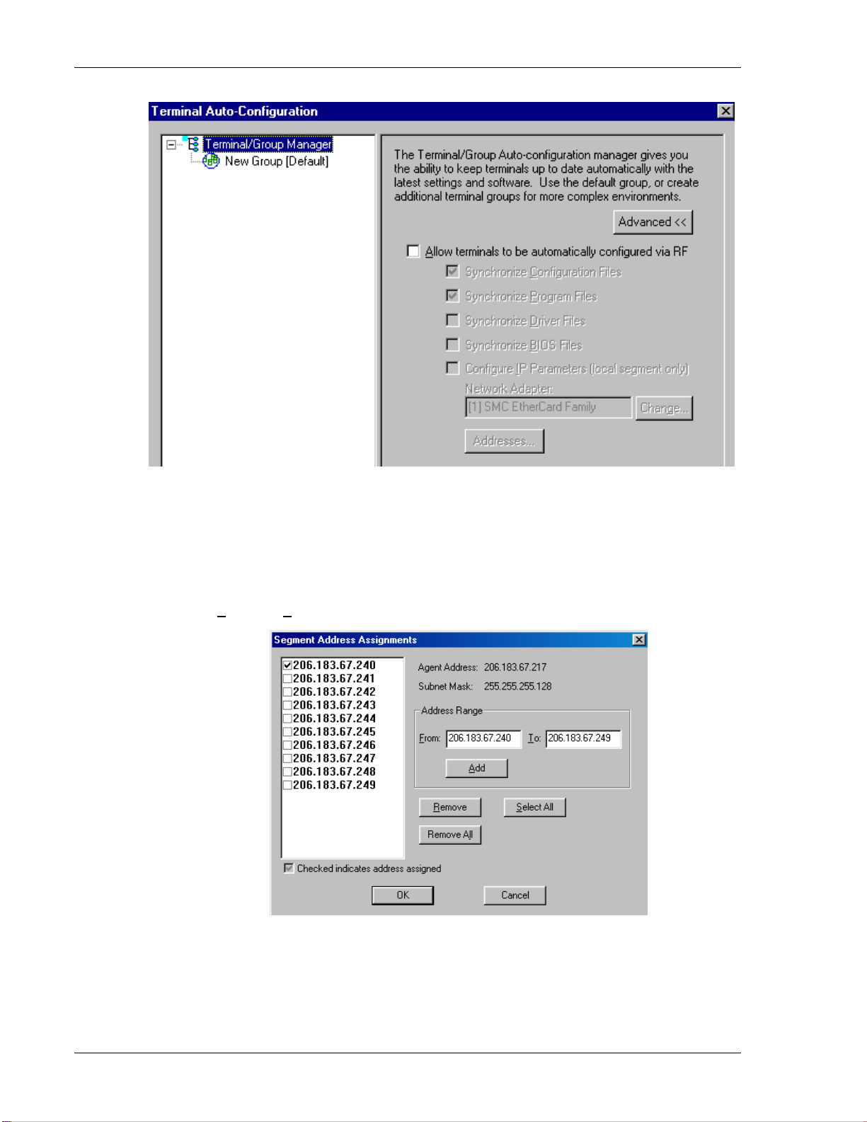
To set the addresses, click on the
Addresses button to access the Segment Address
Assignments dialog box, as shown in the following figure.
2-28 Supported Equipment Manual • January, 2006
Page 39

Terminal Setup
Enter the desired range in the
Add.
From and To boxes as shown above, and then click on
Creating New Groups
New groups, with different configurations, can be created by clicking on
Terminal/Group Manager, and then clicking the right mouse button as shown.
After the new group has been created, the group settings option becomes available for
change, as shown below.
Supported Equipment Manual • January, 2006 2-29
Page 40

Terminal Setup
After the Configuration File and all of the other parameters have been set, the group is
made active by clicking on the
Active check box.
2-30 Supported Equipment Manual • January, 2006
Page 41

Terminal Setup
Clicking on the Thin Mode button will cause all terminals in this group that are currently
running in thick mode to be switched to thin mode the next time Airloader is run on the
terminal.
Click on the
Schedule button to view a dialog box for scheduling an automatic Airloader
update.
elect the desired time and click on OK. Click on Update NS ow and the Airloader “push”
capability controls terminals from this end.
Supported Equipment Manual • January, 2006 2-31
Page 42

Terminal Setup
Setting the Segment
Checking the Segment button restricts a terminal group to a range of IP addresses. The
IP Address can be any valid address on the segment, as it is used
egment. The setting of the Net Mask can be used to restrict the range. This feature is
s
seful for segregating terminal groups by location.
u
only to identify the
Setting Force Reload
Clicking on the F
orce Reload button forces all terminals within a group to be
automatically updated. The following warning message appears.
Click on the
Yes button to force the reload.
Setting the Default Terminal Group
New terminals that have not yet been assigned to any group are initially assigned to the
default group in effect when they are cold booted.
Any group can be made the default group by clicking on the group, and then clicking on
the right mouse button. Then click on the
Make Default option.
Reassigning Terminals
After a terminal has been configured and assigned to the default group, it can be
reassigned to a new group by clicking on the terminal icon as shown below.
Then, holding the mouse button down, drag the terminal icon to the desired group.
2-32 Supported Equipment Manual • January, 2006
Page 43

Terminal Setup
Release the mouse button, which reassigns the terminal.
The next time the terminal is rebooted, it will be reconfigured as defined in the group
specification.
Mobile Device Manager (MDM) Features
Under Tools in Twin Client Manager are the Screen Watcher, Terminal Messenger, and
RF Monitor features.
Note: The terminal may or may not be able to utilize the Screen Watcher or Terminal
Messenger features depending on its authorization codes.
Select Screen Watcher, enter the terminal’s IP address, and click on OK.
A screen will appear with a display resembling the terminal screen.
Supported Equipment Manual • January, 2006 2-33
Page 44

Terminal Setup
Clicking on the
Font button on the upper left brings up a screen in which you can modify
the font settings, as shown below.
Select Terminal Messenger from the Tools menu.
You may enter an Address Range in the
when finished.
Enter a message to send in the space provided, select the termina
by clicking on it in the
Select Terminal(s) column, and click on the S
the message of your choice to the terminal of your choice.
See the example of the Terminal Messenger screen below.
2-34 Supported Equipment Manual • January, 2006
From and To boxes on this screen. Click on Add
l to receive this message
end button to send
Page 45

Terminal Setup
To remove a terminal from the list of terminals receiving you
erminal number in the
t
Click on the appropriate button,
Select Terminal(s) column, and click
Remove All, Select All, or Unselect All, to remove all
terminals, select all terminals, or unselect all terminals from the
r message, click on the
on the R
emove button.
Select Terminal(s) list.
Note: Use the Ctrl and Shift keys to select multiple terminals.
C
Click on the
lose button when finished.
Supported Equipment Manual • January, 2006 2-35
Page 46

Terminal Setup
MD
M’s Find and Identify Features
The
Find feature enables the network manager to rem
otely turn a terminal on and cause it
to make an audible beep so that the terminal can be heard and located within the facility.
The configurable
Identify feature enables you to track the last user of a hand held
terminal. The operator’s logging a password when a terminal session is started enables
the network manager to know who last used the device in the event that it is lost.
To cause the terminal to make audible beeps so that it can be located, enter the IP
address(s) of the terminal, highlight to select, and click on the
Ping button.
TnPing screen will appear. When the terminal is located, it will beep continuously
The
l the user presses any key on the terminal.
unti
Click on Close.
2-36 Supported Equipment Manual • January, 2006
Page 47

Terminal Setup
_
To i dentify the person using the terminal, check Request Login Information.
Click on
Close.
Then from the main menu, select
On the terminal, enter the user’s na
Terminal, and Send Configuration Files to Terminal.
me:
Username:
_ _ _ _ _
The username must be 6 characters long. Press
Enter. Log in to the host as always.
Return to the Terminal Messenger screen, select the IP address, and click on Ping. This
requests the login information from the terminal. The login information is saved on the
PC in the PowerNet Twin Client directory in a file called
ppears as follows:
a
login.txt A sample of the file
.
11:25:16: 04-15-05, 2
time date IP address last login on
of terminal the terminal
07.241.78.248, 12345
Supported Equipment Manual • January, 2006 2-37
Page 48

Terminal Setup
Select RF Monitor from the Tools m
enu.
RF Monitor is an "Over The Air" diagnostic tool. It is used to collect diagnostic trace
information from RF terminals running PowerNet Twin Client software.
It runs on a Windows PC and will send a command to the RF terminal to start tracing.
The terminal, when it receives this command, will start sending the trace information
over the RF link to t
C that can be t to us for analysis.
lick on
C
File to Select Terminal or to Exit.
he PC that issued the command. This will be written to a file on this
senP
Choosing
Terminal IP address and Terminal IP Port, and click on
Select Terminal allows you to view a log of the terminal’s activity. Enter the
OK.
2-38 Supported Equipment Manual • January, 2006
Page 49

Terminal Setup
Click on
log, or select
Edit. Select Find and/or Find Next to search for pieces of information in your
Clear to clear the search.
Click on
Actions to select Start Monitor or Stop Monitor.
licC k on
Tools to choose Set Debug Levels or Settings.
The options in Set
Supported Equipment Manual • January, 2006 2-39
Debug Levels are shown below.
Page 50

Terminal Setup
The maximum log file size can be set under Settings.
Click on
View to show or hide the Toolbar and the Status Bar.
This is the Toolbar. It is found near the top of the screen.
This is the Status Bar. It is found at the bottom of the screen.
Click on
About Twin Client Manager under Help in the main menu to view the following screen.
About RF Monitor under Help to view version number information. Click on
2-40 Supported Equipment Manual • January, 2006
Page 51

Terminal Setup
RF Monitor is a very small program and does not even require installation. Just place it in
a directory on your PC and create a shortcut to run it. It will run on all versions of
ows except V3.1 and Windows 95. Wind
1. Move RF Monitor to a Windows PC with Network access to the RF terminal.
2. Run RF Monitor. (Create a shortcut or do a Start/Run.)
3.
From the pull down menu, select File/Select Terminal.
4. Key in the RF terminal IP address and leave the port at 1802.
5. From the pull down menu, select Tools/Set Debug Levels. Set all levels to 9 except
Datastream and SNA.
Supported Equipment Manual • January, 2006 2-41
Page 52

Terminal Setup
6.
With the RF terminal sitting at the Press Any Key prompt, select Actions/Start
Monitor.
7. Press a key on the RF terminal to open a session, and you should see trace data in the
RF Monitor window. When done, end the trace and the file will be named
tnxxx.yyy.log (where xxx.yyy is the last 2 octets of the RF terminal’s IP address) in
the directory in which RF Monitor was running.
2-42 Supported Equipment Manual • January, 2006
Page 53

Terminal Setup
Common Problems with RF Monitor
•
The trace won’t start.
RF Monitor uses UDP to send commands to the RF device. On busy networks, UDP
packets are not always delivered. The terminal can miss the com
trace. Below are some things that can be useful.
a. Ping the RF terminal from the PC used before starting RF Monitor. (This seems
to "open" a path to the terminal.)
b. Start the Monitor with the terminal at the Press Any Key prompt. (While the
terminal is at this prompt, it is not doing much and has a better chance of hearing
the start trace command.)
• I don't understand what this trace means.
The trace that this tool collects is engineering-level information. It allows an end user
to collect information that can be analyzed by Connect engineering.
It will generally be requested by Connect support to help diagnose a reported
problem.
To be able to read and understand these completely, you need to have an
understanding of:
mand to start the
Supported Equipment Manual • January, 2006 2-43
Page 54

Terminal Setup
a. Emulation protocols (IBM 5250, IBM 3270, DEC VT200, etc.)
b. PowerNet Twin Client products
c. RF Network concepts
d. Wired network concepts
e. Telnet sessions
f. TCP/IP
They are text files that can be read with any editor or viewer and can be useful to end
users and integrators, even if they may not have all the requirements above.
• I have an intermittent problem and it could happen on any one of my 100
terminals. RF Monitor only does one terminal at a time. What can I do?
RF Monitor is not the right diagnostic tool for this type of problem. PowerNet
products have another diagnostic tool that can be used called the "Diagnostic Server".
This tool can be set up to run trace diagnostics on up to 300 terminals at the same
time. This tool will be provided as needed for systems under PowerNet support
agreement OR by T&M when they are not covered.
It also includes the service of a PowerNet support engineer.
Server Transfer is another feature. From the To
The FTP Settings screen appears.
ols menu, select Server Transfer.
To send object editor and configuration files from Windows to your Linux box, enter
your server address, and click on
2-44 Supported Equipment Manual • January, 2006
OK.
Page 55

Terminal Setup
Sending Configuration Files to the 7400/9500 Terminal
1. Cold boot the te
2. Click
3. Go to
Enter.
Start, Settings, and Control Panel on the terminal
4. Double-click o
5. Select the
6. C
hoose a baud rate of
baud rate of
7. Click on
OK.
8. Close the screen.
9. Go into
Tweak Activesync (an Hand Held Products utility) on the PC.
10. If the terminal is in the cradle, make sure the baud rate is 57600, and
choose a baud rate of 115200 if you are using a cable with the terminal.
rminal.
.
Communications
n the
icon.
PC Connection tab.
Infrared 57600 whe
Direct 115200 when using the terminal with the cable.
n using the terminal in the cradle or a
11. Click on
Supported Equipment Manual • January, 2006 2-45
Close Activesync, then click on Open Activesync.
Page 56

Terminal Setup
12. Click on Exit.
13. On the PC, choose
Connection Settings from the File menu in ActiveSync.
The
Connection Settings screen appears as follows.
2-46 Supported Equipment Manual • January, 2006
Page 57

Terminal Setup
14. Make sure that the box is checked in front of the option entitled, Allow serial cable
or infrared connection to this COM port.
15. Double-click on the
Activesync icon.
While ActiveSync is connecting, you will see the following screen.
Supported Equipment Manual • January, 2006 2-47
Page 58

Terminal Setup
When ActiveSync has connected, you will see the screen below.
16. Select
No, and then click Next.
The Connected screen appears.
2-48 Supported Equipment Manual • January, 2006
Page 59

Terminal Setup
17. On the PC, choose
Send Configuration Files to Terminal from the Terminal
menu in Twin Client Manager.
You will see the following screen.
18. Choose Yes.
Supported Equipment Manual • January, 2006 2-49
Page 60

Terminal Setup
19. Choose OK.
20. Click on OK.
21. Cold boot the terminal.
22. On the terminal, select the
IP A r , Subnet Ma and Default Gateway.
23. Enter the
dd ess sk,
Specify an IP Address button.
24. Click on OK.
25. Go to Start, Programs, Cisco, and Client Utility.
26. Select SSID and its Value.
27. Click on OK.
28. Go to Start, Pr g s, Cisco, an lient Util ty
o ram d C i .
29. Select World Mode, and change the Value to Disabled.
30. Click on OK.
31. Warm boot the terminal. To perform a warm boot, press and hold the CTRL and SFT
keys for about 10 seconds, then release.
2-50 Supported Equipment Manual • January, 2006
Page 61

Terminal Setup
Sending Program Files to the 7400/9500 Terminal
1. Cold boot the inal.
2. On the terminal, click on Enter.
3. Double-click on the
4. Double-click on the
5. Select the
6. Choose
7. Choose
8. Cold boot the terminal.
9. Click
10. Go to
Enter.
Start, gs, and Control Pa
11. Double-click on the
12. Select the PC Connection tab.
13. Chose a baud rate of Direct 115200 when using the terminal with the cable, and
choose a baud rate of
14. Go into
15. If the terminal is in the cradle, make sure the baud rate is 57600, and
choose a baud rate of 115200 if you ar ng a cable with the t
term
My Computer icon
IPSM icon.
Twin Client folder.
Delete the File menu.
from
.
Yes at the prompts.
Settin nel.
Communication icon.
Infrared 57600 when using the terminal in the cradle.
Tweak Activesync (an Hand Held Products utility) on the PC.
e usi erminal.
16. Click on Close Activesy click on Open A nc. nc, then ctivesy
Supported Equipment Manual • January, 2006 2-51
Page 62

Terminal Setup
17. Click on
E
xit.
18. Choose C
onnection Settings from the File menu in ActiveS PC. ync on the
The following screen appears.
2-52 Supported Equipment Manual • January, 2006
Page 63

Terminal Setup
19. Make sure tha e box is checked in the option en
or infrared connection to this COM port
20. On the terminal, double-click the Activesync icon.
t th fr of
ont titled,
.
Allow se
rial cable
While ActiveSync is connecting, you will see the following screen.
Supported Equipment Manual • January, 2006 2-53
Page 64

Terminal Setup
When ActiveSync has connected, you will see the screen below.
21. Choose
2-54 Supported Equipment Manual • January, 2006
No, and click on Next.
Page 65

Terminal Setup
Connected screen appears.
The
22. On the PC, select
Send Program Files to Terminal from the Terminal menu in
Twin Client Manager.
The following screen will appear.
23. Click on
OK.
Supported Equipment Manual • January, 2006 2-55
Page 66

Terminal Setup
24. Click on OK.
25. Cold boot the terminal.
26. Click
27. Select the
Enter.
Specify an IP Address button.
28. Enter the IP Address, Subnet Mask, and Default Gateway.
29. Click on OK.
30. Go to Start, Programs, Cisco, and Client Utility.
31. Select SSID and its Value.
32. Click on OK.
33. Go to Start, Programs, Cisco, and Client Utili
ty.
34. Select World Mode, and change the Value to Disabled.
35. Click on OK.
36. Warm boot the terminal. To perform a warm boot, press and hold the CTRL and SFT
keys for about 10 seconds, then release.
2-56 Supported Equipment Manual • January, 2006
Page 67

Chapter 3 • Keyp ad Configuration
Dolphin 7400 43-key Terminal
Keypad Figures
(The keypad figures start on the next page.)
Supported Equipment Manual
•
January, 2006
3-1
Page 68

Keypad Configuration
j
A
_
PF24
ON • SCAN
SFT
▲
NUM
EN
P
F21
F11
F1
a
1
F4
e f
E
F17
4
7
F
i
I
T
◄
PF22
F2 F12
b
B
F15 F14
F5
►
▼
F13
2
C
F16
PF23
c
F3
F6
3
g
F8
G
5
F19
6
F9
k
8
K
9
F H
F18
7
J
F20
F10
TAB
ENT
apostroph
“
d
D
<
h
{
l
L
}
c
~
ESC
ntrst+
e
/
*
cntrst-
m
M
>
q
Q
semicolon
%
u
U
“at” sign
!
Y Z
y
CTRL
O
l brack
+
S
graveac
-
o
s
w
SP
RED
RE
NU
et
cent
bksp
D
M
,
:
#
X V
n
N
.
(
$
?
R T
|
r
v
0
)
^
W
backtab
z
BLUE
BLU
E+RED
BLUE
KEY
TOP
SFT
CTRL
P
r bracket
&
p
=
t
\
x
del
ALT
Dolphin 7400 43-key VT Keyboard
3-2 Supported Equipment Manual • January, 2006
Page 69

Keypad Configuration
j
A
_
◄
F12
B
ON • SCAN
▲
▼
F13
F2
b
2
C
F16
F5
►
erin
c
TA
eof
ENT
F3
apostro
“
d
3
D
p
F6
<
end
cntrst-
ESC
cntrst+
B
phe
/
*
h
F H
J
pa1
F10
5
F8
8
G
F19
K
c
lear
ins
k
pa2
P9
sreq
6
dup
{
~
l
L
9
pa3
}
SFT
NUM
F11
F14
ENT
F21 F22 F23
F1
F24
F4
1
F15
e f a g
E
F17 F18
4
in
fo
F7
i
I
help
fm
rese
7
t
F20
m
M
>
Q
%
U
!
Y Z
.
newline
semicolon
“at” sign
(
q
$
u
ereof
y
CTRL
n
N
?
R T
|
lexit
attn home
r
v
0
)
^
W
z
BLUE
B
BLUE
LUE+RED
O
l bracke
+
S
graveacc
-
backtab
o
s
w
SP
RED
RED
t
:
ent
#
bksp
,
X V
KEYTOP
SFT
CTR
NUM
L
P
r bracket
t
&
x
ALT
p
=
\
del
Dolphin 7400 43-key 3270 Keyboard
Supported Equipment Manual • January, 2006 3-3
Page 70

Keypad Configuration
j
A
_
ON • SCAN
SFT
▲
NU
M
◄
NT
F14
E
F17
I
help
E
F21 F23
a
F
24
F22
F1
F12 F1
B
1
F4
F15
F2 F13 1
b
F5
e f
F H
4
i
nfo
F7
F18
i
7
J
f
m
set
re
F20
F8
field-
F10
►
▼
2
C
F16
G
5
F19
8
K
clear
ENT
F3
c
3
erinp
F6
g
6
s
F9
k
9
ld+
fie
sreq
TA
fld exit
apostinrophe
“
d
D
end
<
h
rol
l up
{
l
L
roll d
own
}
B
ESC
cntrs
/
*
~
cntrst-
t+
m
M
newline
>
Q
semicolon
%
U
“at” sign
!
Y
CTRL
(
q
$
u
ereof
y
n
N
?
R T
|
lexit
attn home
Z
BLUE
r
v
z
BLUE+RED
0
)
^
W
o
O
l bracket
+
s
S
graveaccent
-
w
backtab
SP
RED
REDBLUE
, .
:
#
X V
bksp
P
r bracket
t
&
x
ALT
p
=
\
del
KEYTOP
SFT
CTRL
NUM
Dolphin 7400 43-key 5250 Keyboard
3-4 Supported Equipment Manual • January, 2006
Page 71

Keypad Configuration
Keypad Table
KEY VT
a
b
c
d
e
f
g
h
i
j
k
l
m
n
o
p
q
r
s
t
u
v
w
x
y
z
A
B
C
D
E
F
G
H
I
J
K
L
M
N
O
P
Q
R
S
T
U
V
W
X
Y
Z
/ forward slash
* asterisk
_ underscore
+ addition sign
- dash
: colon
; semicolon
= equal sign
\ backward slash
<a> <a> <a>
<b> <b> <b>
<e> <e> <e>
<f> <f> <f>
<g> <g> <g>
<h> <h> <h>
<i> <i> <i>
<j> <j> <j>
<k> <k> <k>
<l> <l> <l>
<m> <m> <m>
<n> <n> <n>
<o> <o> <o>
<p> <p> <p>
<q> <q> <q>
<r> <r> <r>
<s> <s> <s>
<t> <t> <t>
<u> <u> <u>
<v> <v> <v>
<w> <w> <w>
<x> <x> <x>
<y> <y> <y>
<z> <z> <z>
<Sft><a> <Sft><a> <Sft><a>
<Sft><b> <Sft><b> <Sft><b>
<Sft><c> <Sft><c> <Sft><c>
<Sft><d> <Sft><d> <Sft><d>
<Sft><e> <Sft><e> <Sft><e>
<Sft><f> <Sft><f> <Sft><f>
<Sft><g> <Sft><g> <Sft><g>
<Sft><h> <Sft><h> <Sft><h>
<Sft><i> <Sft><i> <Sft><i>
<Sft><j> <Sft><j> <Sft><j>
<Sft><k> <Sft><k> <Sft><k>
<Sft><l> <Sft><l> <Sft><l>
<Sft><m> <Sft><m> <Sft><m>
<Sft><n> <Sft><n> <Sft><n>
<Sft><o> <Sft><o> <Sft><o>
<Sft><p> <Sft><p> <Sft><p>
<Sft><q> <Sft><q> <Sft><q>
<Sft><r> <Sft><r> <Sft><r>
<Sft><s> <Sft><s> <Sft><s>
<Sft><t> <Sft><t> <Sft><t>
<Sft><u> <Sft><u> <Sft><u>
<Sft><v> <Sft><v> <Sft><v>
<Sft><w> <Sft><w> <Sft><w>
<Sft><x> <Sft><x> <Sft><x>
<Sft><y> <Sft><y> <Sft><y>
<Sft><z> <Sft><z> <Sft><z>
<Red><d> <Red><d> <Red><d>
<Red><h> <Red><h> <Red><h>
<Blue><t> <Blue><t> <Blue><t>
<Blue><s> <Blue><s> <Blue><s>
<Blue><w> <Blue><w> <Blue><w>
<Red><s> <Red><s> <Red><s>
<Red><Blue><u> <Red><Blue><u> <Red><Blue><u>
<Red><t> <Red><t> <Red><t>
<Red><x> <Red><x> <Red><x>
3270 5250
<c> <c> <c>
<d> <d> <d>
Supported Equipment Manual • January, 2006 3-5
Page 72

Keypad Configuration
‘ apostrophe
“ quote
< less than sign
> greater than sign
[ left bracket
] right bracket
{ left brace
} right brace
( left parenthesis
) right parenthesis
? question mark
! exclamation
@ at sign
# pound
$ dollar
% percent
^ carat
& ampersand
` grave accent
~ tilde
| vertical bar
. period
, comma
1
2
3
4
5
6
7
8
9
0
F1
F2
F3
F4
F5
F6
F7
F8
F9
F10
F11
F12
F13
F14
F15
F16
F17
F18
F19
F20
F21
F22
F23
F24
Esc
Num
Alt
Red
Blue
Ctrl
Tab
Enter
<Red><Blue><d> <Red><Blue><d> <Red><Blue><d>
<Blue><d> <Blue><d> <Blue><d>
<Blue><h> <Blue><h> <Blue><h>
<Blue><q> <Blue><q> <Blue><q>
<Red><Blue><s> <Red><Blue><s> <Red><Blue><s>
<Red><Blue><t> <Red><Blue><t> <Red><Blue><t>
<Blue><l> <Blue><l> <Blue><l>
<Blue><p> <Blue><p> <Blue><p>
<Red><q> <Red><q> <Red><q>
<Red><r> <Red><r> <Red><r>
<Blue><r> <Blue><r> <Blue><r>
<Blue><y> <Blue><y> <Blue><y>
<Red><Blue><y> <Red><Blue><y> <R Blue><y> ed><
<Red><w> <Red > <Red><w> ><w
<Red><u> <Red><u> <Red><u>
<Blue><u> <Blue><u> <Blue><u>
<Red><v> <Red><v> <Red><v>
<Blue><x> <Blue><x> <Blue><x>
<Red><Blue>< <Re <w> <Red><Blue><w> w> d><Blue>
<Red><l> <Red d><l> ><l> <Re
<Blue><v> <Blue><v> <Blue><v>
<Num><m> <Num><m> <Num><m>
<Num><o> <Num><o> <Num><o>
<Num><a> <Num><a> <Num><a>
<Num><b> <Num><b> <Num><b>
<Num><c> <Num m><c> ><c> <Nu
<Num><e> <Num><e> <Num><e>
<Num><f> <Num><f> <Num><f>
<Num><g> <Num><g> <Num><g>
<Num><i> <Num><i> <Num><i>
<Num><j> <Num><j> <Num><j>
<Num><k> <Num><k> <Num><k>
<Num><n> <Num><n> <Num><n>
<Red><a> <Red><a> <Red><a>
<Red><b> <Red><b> <Red><b>
<Red><c> <Red><c> <Red><c>
<Red> Red> e> d><e> <e> < < <Re
<Red><f> <Red><f> <Red><f>
<Red><g> <Red><g> <Red><g>
<Red><i> <Red><i> <Red><i>
<Red><j> <Red><j> <Red><j>
<Red><k> <Red><k> <Red><k>
<Red><n> <Red><n> <Red><n>
<Blue><a> <Blue><a> <Blue><a>
<Blue><b> <Blue><b> <Blue><b>
<Blue><c> <Blue><c> <Blue><c>
<Blue><e> <Blue><e> <Blue><e>
<Blue><f> <Blue><f> <Blue><f>
<Blue><g> <Blue><g> <Blue><g>
<Blue><i> <Blue><i> <Blue><i>
<Blue><j> <Blue><j> <Blue><j>
<Blue><k> <Blue><k> <Blue><k>
<Blue><n> <Blue><n> <Blue><n>
--- <Red>< <a> <Red><Blue><a> Blue>
--- <Red><Blue><b> <Red><Blue><b>
--- <Red><Blue><c> <Red><Blue><c>
--- <Red><Blue><e> <Red><Blue><e>
<Esc> <Esc> <Esc>
<Num> <Num> <Num>
<Alt> <Alt> <Alt>
<Red> <Red> <Red>
<Blue> <Blue> <Blue>
<Ctrl> <Ctrl> <Ctrl>
<Tab> <Tab> <Tab>
<Ent> <Ent> <Ent>
3-6 Supported Equipment Manual • January, 2006
Page 73

Keypad Configuration
Sp
Light
Shift
On • Scan
Up
Down
Left
Right
Attention
Backspace
Back tab
Clear
Contrast+
ContrastDelete
Dup
End
EOF
ErEOF
Erinp
Field exit
FieldField+
FM
Help
Home
Info
Insert
Lexit
New line
PA1
PA2
PA3
Reset
Roll up
Roll down
Sys req
<Sp> <Sp> <Sp>
<Light> <Light> <Light>
<Sft> <Sft> <Sft>
<On • Scan> <On • Scan> <On • Scan>
<▲> <▲> <▲>
<▼> <▼> > <▼
<◄> <◄> <◄>
<►> <►> <►>
--- <Blue><z> <Blue><z>
<Red><Sp> <Red><Sp> <Red><Sp>
<Blue><Sp> <Blue><Sp> <Blue><Sp>
--- <Blue><o> <Blue><o>
<Red><Tab> <Red><Tab> <Red><Tab>
< d><Esc> <Red><Esc> <Red><Esc> Re
<Red><Light> <Red><Light> <Red><Light>
--- <Red><Blue><l> ---
--- <Red><Blue><h> <Red><Blue><h>
--- <Blue><Ent> ---
--- <Red><y> <Red><y>
--- <Red><Blue><g> <Red><Blue><g>
--- ed><Blue><Ent> --- <R
--- --- <Red><Blue><n>
--- --- <Red><Blue><o>
--- <Red><Blue><m> <Red><Blue><m>
--- <Blue><m> <Blue><m>
> <Red><z> --- <Red><z
<R <Blue><i> ue><i> --- ed> <Red><Bl
--- <Red><Blue><k> <Red><Blue><k>
--- <Red><Blue><z> <Red><Blue><z>
--- <Red><Blue><q> <Red><Blue><q>
--- <Red><Blue><n> ---
--- d><Blue><o> --- <Re
--- <Red><Blue><p> ---
--- <Red><m> <Red><m>
--- --- <Red><Blue><l>
--- --- <Red><Blue><p>
<Red > <Red><o> --- ><o
Note: Red+Blue=White
Supported Equipment Manual • January, 2006 3-7
Page 74

Keypad Configuration
Dolphin 7400 56-key Terminal
Keypad Figures
(The keypad figures start on the next page.)
3-8 Supported Equipment Manual • January, 2006
Page 75

Keypad Configuration
_
m
R
j
M N
A
a
D
_
W
X
ON • SCAN
SFT
▲
◄
backta
INS
DEL
b
SP
BKSP
ENT
F21 F22 F23
▼
1
F14
4
F2
F4
F15
4
F7 F
F18
7
.
►
F13 FF1
F2 12 F11
2
F1
5
F8
F19 9 F17
8
F10 20 F
0
TAB
ENT
F3
3
6
F6
6
9
,
cntrst-
ESC
cntrst+
rophe
apost
d
n
/
e
E
J
!
@
o
O
“
I
G
b
B
g
{
l
L
C
<
H
~
c
*
h i
f
F
k
K
ALT
T
z
Y
] sign
t
y
=
Z
}
p
P
semi
U
colon
$ %
u
CTRL
>
Q
V
(
q
|
gr
^
v
BLUE
BLUE
) ?
r
aveaccent
#
w
B
LUE+RED
RED
RED
n
[ sig
+
S
&
:
s
\
x
KEYTOP
SFT
CTRL
Dolphin 7400 56-key VT Key
Supported Equipment Manual • January, 2006 3-9
board
Page 76

Keypad Configuration
A
a
_
j
_
m
M
R
W
D
N
X
SFT
ENT
DEL
backtab
INS
SP
ON • SCAN
▲
◄
homeeof
▼
F21 22 cnF23 F
1
F
24
F14
4
7
F4 F15
18
F7
F
20
►
e of
F2 F13 F11 F12F1
2
5
F8 F17
8 9
F10 F
F
16
F19
ENT
3
6
TAB
home
F3 lexit
F6
F9
ESC
trst+
cntrst-
BKSP
f
F
k
K
pa3
}
p
P
semicolon
$ %
u
U
CTRL
G
B
Q
V
{
L
>
|
b
erinp
g
dup
l
newl
q
v
.
~
(
^
attn
BLUE
BLUE
c
C
end
<
h
H
fm
r
w
BLUE+RED
*
reset
) ?
#
0
tgraveaccen
RED
apostrophe
“
d
I
pa1
[ sign
+
S
&
x
RED
i
n
s
,
/
e
E
J
pa2
!
@
o
O
] sign
ALT
=
t
T
z
Z
y
Y
:
\
KEYTOP
SFT
Dolphin 7400 56-key 3270 Keyboard
3-10 Supported Equipment Manual • January, 2006
Page 77

Keypad Configuration
A
a
_
j
_
m
M
R
W
D
N
X
SFT
fld exit
ENT
home
ON • SCAN
◄
▲
▼
►
fld exit
ENT
TAB
home
ESC
cn
trst+
cntr
st-
lexit F3
INS
DEL
backtab
SP
BKSP
f
F
k
K
roll↓
}
p
P
semicolon
u
U
$ %
B
G
{
L
>
Q
V
F21 F F23
F1
1
F24
F4
4
F17
F7
7
.
(
C
end
<
H
attn
fm
graveaccent
w
erinp
|
b
g
roll↑
l
newl
q
v
~
^
22
2 F13 F1211
F F
2 3
F
15 F14
F16
5
F
8
1
F8
F19
8 9
F10 F20
c
h
r
0
*
reset
) ?
#
apostrophe
“
d
i
I
field-
n
[ sign
+
s
S
\
&
x
/
:
,
6
F6
E
J
O
T
z
Y
F9
field+
!
] sign
e
@
o
=
t
Z
y
CTRL
BLUE
BLUE
BLUE+RED
RED
RED
ALT
KEYTOP
SFT
Dolphin 7400 56-key 5250 Keyboard
Supported Equipment Manual • January, 2006 3-11
Page 78

Keypad Configuration
Keypad Table
Key VT
a
b
c
d
e
f
g
h
i
j
k
l
m
n
o
p
q
r
s
t
u
v
w
x
y
z
A
B
C
D
E
F
G
H
I
J
K
L
M
N
O
P
Q
R
S
T
U
V
W
X
Y
Z
/ forward slash
* asterisk
_ underscore
+ addition sign
- dash
: colon
; semicolon
= equal sign
<a> <a> <a>
<f> <f> <f>
<g> <g> <g>
<h> <h> <h>
<i> <i> <i>
<j> <j> <j>
<k> <k> <k>
<l> <l> <l>
<m> <m> <m>
<n> <n> <n>
<o> <o> <o>
<p> <p> <p>
<q> <q> <q>
<r> <r> <r>
<s> <s> <s>
<t> <t> <t>
<u> <u> <u>
<v> <v> <v>
<w> <w> <w>
<x> <x> <x>
<y> <y> <y>
<z> <z> <z>
<Sft><a> <Sft><a> <Sft><a>
<Sft><b> <Sft><b> <Sft><b>
<Sft><c> <Sft><c> <Sft><c>
<Sft><d> <Sft><d> <Sft><d>
<Sft><e> <Sft><e> <Sft><e>
<Sft><f> <Sft><f> <Sft><f>
<Sft><g> <Sft><g> <Sft><g>
<Sft><h> <Sft><h> <Sft><h>
<Sft><i> <Sft><i> <Sft><i>
<Sft><j> <Sft><j> <Sft><j>
<Sft><k> <Sft><k> <Sft><k>
<Sft><l> <Sft><l> <Sft><l>
<Sft><m> <Sft><m> <Sft><m>
<Sft><n> <Sft><n> <Sft><n>
<Sft><o> <Sft><o> <Sft><o>
<Sft><p> <Sft><p> <Sft><p>
<Sft><q> <Sft><q> <Sft><q>
<Sft><r> <Sft><r> <Sft><r>
<Sft><s> <Sft><s> <Sft><s>
<Sft><t> <Sft><t> <Sft><t>
<Sft><u> <Sft><u> <Sft><u>
<Sft><v> <Sft><v> <Sft><v>
<Sft><w> <Sft><w> <Sft><w>
<Sft><x> <Sft><x> <Sft><x>
<Sft><y> <Sft><y> <Sft><y>
<Sft><z> <Sft><z> <Sft><z>
<Red><d> <Red><d> <Red><d>
<Red><h> <Red><h> <Red><h>
<Blue><t> <Blue><t> <Blue><t>
<Blue><s> <Blue><s> <Blue><s>
<Blue><w> <Blue><w> <Blue><w>
<Red><s> <Red><s> <Red><s>
<Red><Blue><u> <Red><Blue><u> <Red><Blue><u>
<Red><t> <Red><t> <Red><t>
NOTE: RED + BLUE = WHITE
3270 5250
<b> <b> <b>
<c> <c> <c>
d> <d> <d> <
e> <e> <e> <
3-12 Supported Equipment Manual • January, 2006
Page 79

Keypad Configuration
\ backward slash
‘ apostrophe
“ quote
! exclamation
? question mark
< less than sign
> greater than sign
[ left bracket
] right bracket
{ left brace
} right brace
( left parenthesis
) right parenthesis
@ at sign
# pound
$ dollar
% percent
^ carat
& ampersand
` grave accent
~ tilde
| vertical bar
. period <.> <.> <.>
, comma <,> <,> <,>
1
2
3
4
5
6
7
8
9
0
F1
F2
F3
F4
F5
F6
F7
F8
F9
F10
F11
F12
F13
F14
F15
F16
F17
F18
F19
F20
F21
F22
F23
F24
Shift
Esc
Alt
Red
Blue
Ctrl
Tab
<Red><x> <Red><x> <Red><x>
<Red><Blue><d> <Red><Blue><d> <Red><Blue><d>
<Blue><d> <Blue><d> <Blue><d>
<Blue><o> <Blue><o> <Blue><o>
<Blue><r> <Blue><r> <Blue><r>
<Blue><h> <Blue><h> <Blue><h>
<Blue><q> <Blue><q> <Blue><q>
<Red><Blue><s> <Red><Blue><s> <Red><Blue><s>
<Red><Blue><t> <Red><Blue><t> <Red><Blue><t>
<Blue><l> <Blue><l> <Blue><l>
<Blue><p> <Blue><p> <Blue><p>
<Red><q> <Red><q> <Red><q>
<Red><r> <Red><r> <Red><r>
<Red><o> <Red><o> <Red><o>
<Red><w> <Red><w> <Red><w>
<Red><u> <Red><u> <Red><u>
<Blue><u> <Blue><u> <Blue><u>
<Red><v> <Red><v> <Red><v>
<Blue><x> <Blue>< <Blue><x> x>
<Red><Blue><w> <Red><Blue><w> <Red><Blue><w>
<Red><l> <Red><l> <Red><l>
<Blue><v> <Blue><v> <Blue><v>
<1> <1> <1>
<2> <2> <2>
<3> <3> <3>
<4> <4> <4>
<5> <5> <5>
<6> <6> <6>
<7> <7> <7>
<8> <8> <8>
<9> <9> <9>
<0> <0> <0>
<Red><1> <Red><1> <Red><1>
<Red><2> <Red><2> <Red><2>
<Red><3> <Red><3> <Red><3>
<Red><4> <Red><4> <Red><4>
<Red><5> <Red><5> <Red><5>
<Red><6> <Red><6> <Red><6>
<Red><7> <Red><7> <Red><7>
<Red><8> <Red><8> <Red><8>
<Red><9> <Red><9> <Red><9>
<Red><0> <Red><0> <Red><0>
<Blue><1> <Blue><1> <Blue><1>
<Blue><2> <Blue><2> <Blue><2>
<Blue><3> <Blue><3> <Blue><3>
<Blue><4> <Blue><4> <Blue><4>
<Blue><5> <Blue><5> <Blue><5>
<Blue><6> <Blue><6> <Blue><6>
<Blue><7> <Blue><7> <Blue><7>
<Blue><8> <Blue><8> <Blue><8>
<Blue><9> <Blue><9> <Blue><9>
<Blue><0> <Blue><0> <Blue><0>
--- <Red><Blue><1> <Red><Blue><1>
--- <Red><Blue><2> <Red><Blue><2>
--- <Red><Blue><3> <Red><Blue><3>
--- <Red><Blue><4> <Red><Blue><4>
<Sft> <Sft> <Sft>
<Esc> <Esc> <Esc>
<Alt> <Alt> <Alt>
<Red> <Red> <Red>
<Blue> <Blue> <Blue>
<Ctrl> <Ctrl> <Ctrl>
<Tab> <Tab> <Tab>
Supported Equipment Manual • January, 2006 3-13
Page 80

Keypad Configuration
Enter
Sp
Light
Del
Ins
Backspace
On • Scan <On • Scan> <On • Scan> <On • Scan>
Up
Down
Left
Right
Attention
Backtab
Contrast+
ContrastDup
End
EOF
Erinp
Field exit
FieldField+
FM
Home
Lexit
New line
PA1
PA2
PA3
Reset
Roll up
Roll down
<Ent> <Ent> <Ent>
<Sp> <Sp> <Sp>
<Light> <Light> <Light>
<Del> <Del> <Del>
<Ins> <Ins> <Ins>
<Bksp> <Bksp> <Bksp>
<▲> <▲> <▲>
<▼> <▼> <▼>
<◄> <◄> <◄>
<►> <►> <►>
--- <Blue><m> <Blue><m>
<Blue><Sp> <Blue><Sp> <Blue><Sp>
<Red><Tab> <Red><Tab> <Red><Tab>
<Red><Esc> <Red><Esc> <Red><Esc>
--- <Red><Blue><l> ---
--- <Red><Blue><h> <Red>< ><h> Blue
--- <Bl --- ue><Ent>
--- <Red> ue><g> <Red><Blue><g> <Bl
--- --- <Red><Blue><Ent>
--- --- <Red><Blue><n>
--- --- <Red><Blue><o>
--- <Red><Blue><r> <Red><Blue><r>
--- <R Ent> <Re E ed>< d>< nt>
--- <Bl Ins> <Blue><Insue>< >
--- <Red><Blue><q> <Red><Blue><q>
--- <Red><Blue><n> ---
--- <Red><Blue><o> ---
--- <Red><Blue><p> - --
--- < m> <Red < Red>< > m>
--- --- <Red><Blue><l>
--- --- <Red><Blue><p>
Note: Red+Blue=White
3-14 Supported Equipment Manual • January, 2006
Page 81

Keypad Configuration
Dolphin 7400 35-key Terminal
Keypad Figures
(The keypad figures start on the next page.)
Supported Equipment Manual • January, 2006 3-15
Page 82

Keypad Configuration
_
A
j
_
A
y
ON • SCAN
SFT
▲
ALPHA
F11
ENT
F22 F23
F21
F1
1
BC
F14
F24
abc
F4
4
JKL
F17
kl
F7
7
STU
stu
◄
▼
F12
2
DEF
“at”sig
F15
5
MNO
8
VWX
►
ENT
F2
def
n
F5
mn
F8
x
vw
F13
o
GHI
F16
PQR
F19 F18
YZ yz
TAB
F3
3
ghi
F6
6
pq
F9
9
cntrst
r
cntrst-
ESC
+
/
(
pound
$
.
>
apostroph
F1
CTRL
semicolon
*
+
backtab
F20
F2
|
e
“
SP
BLUE
BLUE+RED
BLUE
KEYTOP
SFT
grave
)
CTR
accent
0
?
L
F10
l bracket
~
F
DE
RED
RED
LPHA
3
L
{
carat
<
r bracket
:
=
ampersa
\
%
,
F4
BKSP
ALT
}
nd
!
Dolph 35 K-key VT
Note: C Alpha + k
3-16 Supported Equipment Manual • January, 2006
in 7400 eyboard
aps are Shift + e
top character
Page 83

Keypad Configuration
_
A
A
j
_
p
SFT
ON • SCAN
▲
ALPHA
attn
◄
F12
DEF
F15
MNO
VWX
F20
▼
“at”sign
5
fm
8
graveaccen
0
)
erinp
eof
F11
BC
F14
ENT
F F22 F23
21
F1
1
abc
F
24
F4
4
JKL
F17
kl
re
set
F7
7
STU
$
p
ound
stu
|
.
>
2
►
F2
def
F5
mno
F8
vwx
t
F10
cntrst-
ESC
cntrst+
TAB
erinp
eof
F1
attn
ENT
F3
3
sreq
ghi
F6
GHI
F16
6
R
PQ
1 F18
F3 9
home
pqr
F9
9
YZ
<
carat
yz
%
,
“
+
bktab
semicolon
*
F2
end
SP
BLUE
BLUE
?
ereo
help
BLUE+RED
l bracket
~
F3
ins
f
DEL
RED
RED
apost
rophe
/
F1
( =
CTRL
KEYTOP
SFT
CTRL
LPHA
Dolphin 7400 35-key 3270 Keyboard
Note: Ca
s are Shift + Alpha + keytop character
{
clea
r bracket
:
ampersand
r
\
BKSP
F4
ALT
}
!
Supported Equipment Manual • January, 2006 3-17
Page 84

Keypad Configuration
_
A
A
j
_
p
SFT
ON • SCAN
▲
PHA
AL
erinp
fex
F1
ENT
F21 F22 F23
1
F1
1
F24
abc
F4
BC
F1
4
4
L
JK
F1
reset
7
kl
F7
7
pou
stu
nd
|
.
STU
$
>
◄
attnit
▼
F2
5
8
0
2
def
F5
F8
vw
F10
o
x
F12
DEF
“at”sign
F15
MmnNO
F18
VWX
graveaccent
F20
)
fm
►
fexit
F13
G
HI
6
F1
PQ
R
F1
9
YZ
<
erinp
ENT
3
sreq
home
9
carat
,
6
TAB
attn
F3
ghi
F6
pqr
F9
yz
%
ESC
cntrst+
cntr
st-
strophe
apo
/
F1
(
CTRL
Dolphin 7400 35-key 5250 Keyboard
Note: Ca
semi
“
backtab
+
*
BLUE
BLUE
colon
F2
end
help
SP
BLUE+RED
l bracket
~
?
{
:
F3
ereof
ins
clear
=
ampersand
\
DEL
RED
RED
KEYTOP
SFT
CTRL
LPHA
s are Shift + Alpha + keytop character
r bracket
F4
BKSP
ALT
}
!
3-18 Supported Equipment Manual • January, 2006
Page 85

Keypad Configuration
Keypad Table
Key VT 3270 5250
NOTE: RED + BLUE = WHITE
a
b
c
d
e
f
g
h
i
j
k
l
m
n
o
p
q
r
s
t
u
v
w
x
y
z
A
B
C
D
E
F
G
H
I
J
K
L
M
N
O
P
Q
R
S
T
U
V
W
X
Y
Z
/ forward slash
* asterisk
_ underscore
+ addition sign
- dash <Blue><,> <Blue><,> <Blue><,>
: colon
; semicolon
= equal sign
<Alpha><1> <Alpha><1> <Alpha><1>
><1><1> <Alpha><1><1> <Alpha><1><1> <Alpha
1><1><1> <Alpha><1><1><1> <Alpha><1><1><1> <Alpha><
<Alpha><2> <Alpha><2> <Alpha><2>
<Alpha><2><2> <Alpha><2><2> <Alpha><2><2>
<Alpha><2><2><2> <Alpha><2><2><2> <Alpha><2><2><2>
<Alpha><3> <Alpha><3> <Alpha><3>
<Alpha><3><3> <Alpha><3><3> <Alpha><3><3>
<Alpha><3><3><3> <Alpha><3><3><3> <Alpha><3><3><3>
<Alpha><4> <Alpha><4> <Alpha><4>
<Alpha><4><4> <Alpha><4><4> <Alpha><4><4>
<Alpha><4><4><4> <Alpha><4><4><4> <Alpha><4><4><4>
<Alpha><5> <Alpha><5> <Alpha><5>
<Alpha><5><5> <Alpha><5><5> <Alpha><5><5>
<Alpha><5><5><5> <Alpha><5><5><5> <Alpha><5><5><5>
<Alpha><6> <Alpha><6> <Alpha><6>
<Alpha><6><6> <Alpha><6><6> <Alpha><6><6>
<Alpha><6><6><6> <Alpha><6><6><6> <Alpha><6><6><6>
<Alpha><7> <Alpha><7> <Alpha><7>
<Alpha><7><7> <Alpha><7><7> <Alpha><7><7>
<Alpha><7><7><7> <Alpha><7><7><7> <Alpha><7><7><7>
<Alpha><8> <Alpha><8> <Alpha><8>
<Alpha><8><8> <Alpha><8><8> <Alpha><8><8>
<Alpha><8><8><8> <Alpha><8><8><8> <Alpha><8><8><8>
<Alpha><9> <Alpha><9> <Alpha><9>
<Alpha><9><9> <Alpha><9><9> <Alpha><9><9>
<Sft><Alpha><1> <Sft><Alpha><1> <Sft><Alpha><1>
<Sft><Alpha><1><1> <Sft><Alpha><1><1> <Sft><Alpha><1><1>
<Sft><Alpha><1><1><1> <Sft><Alpha><1><1><1> <Sft><Alpha><1><1><1>
<Sft><Alpha><2> <Sft><Alpha><2> <Sft><Alpha><2>
<Sft><Alpha><2><2> <Sft><Alpha><2><2> <Sft><Alpha><2><2>
<Sft><Alpha><2><2><2> <Sft><Alpha><2><2><2> <Sft><Alpha><2><2><2>
<Sft><Alpha><3> <Sft><Alpha><3> <Sft><Alpha><3>
<Sft><Alpha><3><3> <Sft><Alpha><3><3> <Sft><Alpha><3><3>
<Sft><Alpha><3><3><3> <Sft><Alpha><3><3><3> <Sft><Alpha><3><3><3>
<Sft><Alpha><4> <Sft><Alpha><4> <Sft><Alpha><4>
<Sft><Alpha><4><4> <Sft><Alpha><4><4> <Sft><Alpha><4><4>
<Sft><Alpha><4><4><4> <Sft><Alpha><4><4><4> <Sft><Alpha><4><4><4>
<Sft><Alpha><5> <Sft><Alpha><5> <Sft><Alpha><5>
<Sft><Alpha><5><5> <Sft><Alpha><5><5> <Sft><Alpha><5><5>
<Sft><Alpha><5><5><5> <Sft><Alpha><5><5><5> <Sft><Alpha><5><5><5>
<Sft><Alpha><6> <Sft><Alpha><6> <Sft><Alpha><6>
<Sft><Alpha><6><6> <Sft><Alpha><6><6> <Sft><Alpha><6><6>
<Sft><Alpha><6><6><6> <Sft><Alpha><6><6><6> <Sft><Alpha><6><6><6>
<Sft><Alpha><7> <Sft><Alpha><7> <Sft><Alpha><7>
<Sft><Alpha><7><7> <Sft><Alpha><7><7> <Sft><Alpha><7><7>
<Sft><Alpha><7><7><7> <Sft><Alpha><7><7><7> <Sft><Alpha><7><7><7>
<Sft><Alpha><8> <Sft><Alpha><8> <Sft><Alpha><8>
<Sft><Alpha><8><8> <Sft><Alpha><8><8> <Sft><Alpha><8><8>
<Sft><Alpha><8><8><8> <Sft><Alpha><8><8><8> <Sft><Alpha><8><8><8>
<Sft><Alpha><9> <Sft><Alpha><9> <Sft><Alpha><9>
<Sft><Alpha><9><9> <Sft><Alpha><9><9> <Sft><Alpha><9><9>
<Blue><F1> <Blue><F1> <Blue><F1>
<Blue><F2> <Blue><F2> <Blue><F2>
<Sft><F3> <Sft><F3> <Sft><F3>
<Sft><F2> <Sft><F2> <Sft><F2>
<Blue><F4> <Blue><F4> <Blue><F4>
<Red><Blue><F2> <Red><Blue><F2> <Red><Blue><F2>
<Sft><F4> <Sft><F4> <Sft><F4>
Supported Equipment Manual • January, 2006 3-19
Page 86

Keypad Configuration
\ backward slash
‘ apostrophe
“ quote
! exclamation
? question mark
< less than sign <Sft><,> <Sft><,> <Sft><,>
> greater than sign <Sft><.> <Sft><.> <Sft><.>
[ left bracket
] right bracket
{ left brace
} right brace
( left parenthesis
) right parenthesis
@ at sign
# pound <Red><Blue><.> <Red><Blue><.> <Red><Blue><.>
$ dollar <Blue><.> <Blue><.> <Blue><.>
% percent <Red><,> <Red><,> <Red><,>
^ carat <Red><Blue><,> <Red><Blue><,> <Red><Blue><,>
& ampersand
` grave accent
~ tilde
| vertical bar <Red><.> <Red><.> <Red><.>
. period <.> <.> <.>
, comma <,> <,> <,>
1
2
3
4
5
6
7
8
9
0
F1
F2
F3
F4
F5
F6
F7
F8
F9
F10
F11
F12
F13
F14
F15
F16
F17
F18
F19
F20
F21
F22
F23
F24
Shift
Esc
Alpha
Alt
Red
Blue
Ctrl
<Blue><Bksp> <Blue><Bksp> <Blue><Bksp>
<Red><Blue><F1> <Red><Blue><F1> <Red><Blue><F1>
<Red><F1> <Red><F1> <Red><F1>
<Red><Bksp> <Red><Bksp> <Red><Bksp>
<Red><F2> <Red><F2> <Red><F2>
<Red><Blue><F3> <Red><Blue < ed><B e><F3> ><F3> R lu
<Red><Blue><F4> <Red><Blue><F4> <Red><Blue><F4>
<Red><F3> <Red><F3> <Red><F3>
<Red><F4> <Red><F4> <Red><F4>
<Sft><F1> <Sft><F1> <Sft><F1>
<Sft><0> <Sft><0> <Sft ><0>
<Red><Blue><5> <Red><Blue><5> <Red><Blue><5>
<Red><Blue><Bksp> <Red><Blue><Bksp> <Red><Blue><Bksp>
<Red><Blue><0> <Red><Blue><0> <Red><Blue><0>
<Blue><F3> <Blue><F3> <Blue><F3>
<1> <1> <1>
<2> <2> <2>
<3> <3> <3>
<4> <4> <4>
<5> <5> <5>
<6> <6> <6>
<7> <7> <7>
<8> <8> <8>
<9> <9> <9>
<0> <0> <0>
<Red><1> <Red><1> <Red><1>
<Red><2> <Red><2> <Red><2>
<Red><3> <Red><3> <Red><3>
<Red><4> <Red><4> <Red><4>
<Red><5> <Red><5> <Red><5>
<Red><6> <Red><6> <Red><6>
<Red><7> <Red><7> <Red><7>
<Red><8> <Red><8> <Red><8>
<Red><9> <Red><9> <Red><9>
<Re <Red><0> <Red>d><0> <0>
<Blu <Blue><1 <Blue><1> e><1> >
<Blue><2> <Blue><2> <Blue><2>
<Blue><3> <Blue><3> <Blue><3>
<Blue><4> <Blue <Blue><4> ><4>
<Blue><5> <Blue><5> <Blue><5>
<Blue><6> <Blue><6> <Blue><6>
<Blue><7> <Blue><7> <Blue><7>
<Blue><8> <Blue><8 > <Blue><8>
<Blue><9> <Blue><9> <Blue><9>
<Blue><0> <Blue><0> <Blue><0>
--- <Red><Blue><1> <Red><Blue><1>
--- <Red><Blue><2> <Red><Blue><2>
--- <Red><Blue <Red><Blue><3> ><3>
--- <Red><Blue><4> <Red><Blue><4>
<Sft> <Sft> <Sft>
<Esc> <Esc> <Esc>
<Alpha> <Alpha> <Alpha>
<Alt> <Alt> <Alt>
<Red> <Red> <Red>
<Blue> <Blue> <Blue>
<Ctrl> <Ctrl> <Ctrl>
3-20 Supported Equipment Manual • January, 2006
Page 87

Keypad Configuration
Tab
Enter
Sp
Light
Del
Backspace
On • Scan
F1
F2
F3
F4
Up
Down
Left
Right
Attention
Backtab
Clear
Contrast+
ContrastEnd
EOF
Erinp
ErEOF
Field exit
FM
Help
Home
Ins
Reset
Sys req
<Tab> <Tab> <Tab>
<Ent> <Ent> <Ent>
<Sp> <Sp> <Sp>
<Light> <Light> <Light>
<Del> <Del> <Del>
<Bksp> <Bksp> <Bksp>
<On • Scan> <On • Scan> <On • Scan>
<F1> <F1> <F1>
<F2> <F2> <F2>
<F3> <F3> <F3>
<F4> <F4> <F4>
<▲> <▲> <▲ >
<▼> < <▼> ▼>
<◄> <◄> <◄>
<►> <►> <►>
--- <Red><Ent> <Red><Ent>
<Blue><Sp> <Blue><Sp> <Blue><Sp>
--- <Red><Del> <Red><Del>
<Red><Tab> <Red><Tab> <Red><Tab>
<Red><Esc> <Red><Esc> <Red><Esc>
--- <Red><Blue><Sp> <Red><Blue><Sp>
--- <Blue><Ent> ---
--- <Red>< ><Ent> <Red><Blue><Ent> Blue
--- <Blue><Del> <Blue><Del>
--- --- <Blue><Ent>
--- <Red><Blue><8> <Red><Blue><8>
--- <Red><Sp> <Red><Sp>
--- <Red><Blue><9> <Red><Blue><9>
--- <Red><Blue><Del> <Red><Blue><Del>
--- <Red><Blue><7> <Red><Blue><7>
--- <Red><Blue><6> <Red><Blue><6>
Note: Red+Blue=White
Supported Equipment Manual • January, 2006 3-21
Page 88

Keypad Configuration
Dolphin 9500 43-key Terminal
Keypad Figures
The keypad figures begin on the next page.
3-22 Supported Equipment Manual • January, 2006
Page 89
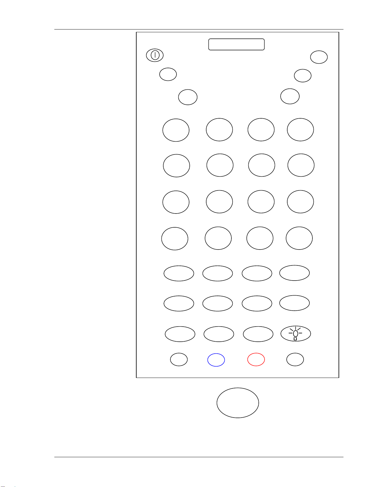
Keypad Configuration
j
A
_
A
Info
Field-
ON • SCAN
vol+ pg↑
▲
SFT
◄
NUM
F
F
F
14
E
17
I
Help
F1
a
B
1
F4
F15
e
F H
4
F7
F18
i
7
J
FM
Reset
F20
vol- pg↓
▼
F2 F13F12 11
b
2
C D
F5
F16
f
G
5
F8
F19
8
K
Clear
F10
►
c
Erinp
g
Ins
k
Field+
F3
3
F6
6
F9
9
SReq
Fl t
d Exi
ENT
apo
“
as
<
R
{
L
Roll
}
TAB
strophe
d
terisk
h
oll Up
l
Down
ESC
cntrst+
send
end
~
/
cntrst-
Home
Lexit
ttn
m
M
NewLine
>
q
Q
semicolon
%
u
U
rt
sta
Y
CTRL
y
n
N
(
EREOF
?
0
)
r
$
Z
|
!
“
at”sign
BLUE
BLUE
v
z
^
BLU
W
E+RED
o
O
l bracket
+
S R T
graveaccent
-
, .
:
s
#
w
backtab
bksp
SP
RED
RED
XV
p
P
r bracket
=
t
on
\
x
del
ALT
Exclamati
&
KEYTOP
SFT
CT
NUM
RL
Dolphin 9500 43-key VT Key
Supported Equipment Manual • January, 2006 3-23
board
Page 90

Keypad Configuration
j
A
_
ON • SCAN
vol+ pg↑
▲
SFT
◄
vol- pg↓
M
NU
F21 F22 F23
F1
a
B
F24
1
F4
F15
F14
e f
E
F
17
4
fo
in
F7
F18
i
I
help
fm
reset
7
J
F20
F2 F1 F11
b
F5 F1
F H
F8 F19
pa1
F
10
▼
3 F12
2
C
6
G
5
8
K
Clear
►
c
erinp
g
ins
k
pa2
eo
F3
3
F6
6
F9
9
SReq
TAB
f
ENT
apostrophe
“
d
D
asterisk
<
h
d
up
{
l
L
p
a3
}
send
~
/
ESC
cntr
end
cntrst-
st+
m
M
e
newlin
>
Q
semicolon
%
start
Y
L
q
u
CTR
(
$
y
n
N
ereof
?
R T
“at”sig
|
attn
Z
BLUE
r
v
lexit
z
0
)
n
^
WU
home
BLUE+RED
S
O
gra
-
bac
bracket
l
+
ktab
RED
o
s
w
SP
REDLUEB
, .
:
#
X V
bksp
P
r br
excl
&
acket
t
amation
veaccent
x
ALT
p
=
\
del
KEYTOP
SFT
CTRL
NUM
Dolphin 9500 43-key 3270 Keyboa
3-24 Supported Equipment Manual • January, 2006
rd
Page 91

Keypad Configuration
j
A
_
ON • SCAN
pg↑
vol+
▲
SFT
◄
vol- pg↓
NUM
F21 F23
F22
F1
a
B
F24
F4
1
F15
F14
e f
E
info
F17 F19
F7
F H
4
F18
i
I
help
fm
reset
7
J
field-
F2
0
▼
F13
F2 F12 F11
b
2
C D
F5
F16
G
F8
8
K
clear
0
F1
►
F3
c
3
erinp
F6
g
6 5
ins
F9
k
9
field+
sre
q
fld exit
ENT
apost
“
asteris
<
roll up
{
L
roll do
}
TAB
rophe
d
h
l
wn
cntrst+
send
k
end
~
/
cntrst-
ESC
m
M
newline
>
Q
semicolon
%
U
start
Y
(
q
$
u
y
CTRL
n
N
ereof
?
R T
“at”sign
|
attn
Z
BLUE
r
v
lexit
z
0
)
^
W
home
BLUE+RED
o
O
l bracket
+
s
S
graveaccent
-
w
backtab
SP
RED
RED BLUE
:
#
bksp
,.
X V
KEYTOP
SFT
CTRL
NUM
p
P
r bracke
t
exclamation
&
x
ALT
t
=
\
del
Dolphin 9500 43-key 5250 Keyboard
Supported Equipment Manual • January, 2006 3-25
Page 92

Keypad Configuration
Keypad Table
KEY VT
a
b
c
d
e
f
g
h
i
j
k
l
m
n
o
p
q
r
s
t
u
v
w
x
y
z
A
B
C
D
E
F
G
H
I
J
K
L
M
N
O
P
Q
R
S
T
U
V
W
X
Y
Z
/ forward slash
* asterisk
_ underscore
+ addition sign
- dash
: colon
; semicolon
= equal sign
\ backward slash
<a> <a> <a>
<b> <b> <b>
<g> <g> <g>
<h> <h> <h>
<i> <i> <i>
<j> <j> <j>
<k> <k> <k>
<l> <l> <l>
<m> <m> <m>
<n> <n> <n>
<o> <o> <o>
<p> <p> <p>
<q> <q> <q>
<r> <r> <r>
<s> <s> <s>
<t> <t> <t>
<u> <u> <u>
<v> <v> <v>
<w> <w> <w>
<x> <x> <x>
<y> <y> <y>
<z> <z> <z>
<Sft><a> <Sft><a> <Sft><a>
<Sft><b> <Sft><b> <Sft><b>
<Sft><c> <Sft><c> <Sft><c>
<Sft><d> <Sft><d> <Sft><d>
<Sft><e> <Sft><e> <Sft><e>
<Sft><f> <Sft><f> <Sft><f>
<Sft><g> <Sft><g> <Sft><g>
<Sft><h> <Sft><h> <Sft><h>
<Sft><i> <Sft><i> <Sft><i>
<Sft><j> <Sft><j> <Sft><j>
<Sft><k> <Sft><k> <Sft><k>
<Sft><l> <Sft><l> <Sft><l>
<Sft><m> <Sft><m> <Sft><m>
<Sft><n> <Sft><n> <Sft><n>
<Sft><o> <Sft><o> <Sft><o>
<Sft><p> <Sft><p> <Sft><p>
<Sft><q> <Sft><q> <Sft><q>
<Sft><r> <Sft><r> <Sft><r>
<Sft><s> <Sft><s> <Sft><s>
<Sft><t> <Sft><t> <Sft><t>
<Sft><u> <Sft><u> <Sft><u>
<Sft><v> <Sft><v> <Sft><v>
<Sft><w> <Sft><w> <Sft><w>
<Sft><x> <Sft><x> <Sft><x>
<Sft><y> <Sft><y> <Sft><y>
<Sft><z> <Sft><z> <Sft><z>
<Red><p> <Red><p> <Red><p>
<Red><Blue><h> <Red><Blue><h> <Red><Blue><h>
<Blue><t> <Blue><t> <Blue><t>
<Blue><s> <Blue><s> <Blue><s>
<Blue><w> <Blue><w> <Blue><w>
<Red><s> <Red><s> <Red><s>
<Red><Blue><u> <Red><Blue><u> <Red><Blue><u>
<Red><t> <Red><t> <Red><t>
<Red><x> <Red><x> <Red><x>
3270 5250
<c> <c> <c>
<d> <d> <d>
<e> <e> <e>
<f> <f> <f>
3-26 Supported Equipment Manual • January, 2006
Page 93

Keypad Configuration
‘ apostrophe
“ quote
< less than sign
> greater than sign
[ left bracket
] right bracket
{ left brace
} right brace
( left parenthesis
) right parenthesis
? question mark
! exclamation
@ at sign
# pound
$ dollar
% percent
^ carat
& ampersand
` grave accent
~ tilde
| vertical bar
. period
, comma
1
2
3
4
5
6
7
8
9
0
F1
F2
F3
F4
F5
F6
F7
F8
F9
F10
F11
F12
F13
F14
F15
F16
F17
F18
F19
F20
F21
F22
F23
F24
Esc
Shift
Num
Alt
Red
Blue
Ctrl
Tab
<Red><Blue><d> <Red><Blue><d> <Red><Blue><d>
<Blue><d> <Blue><d> <Blue><d>
<Blue><h> <Blue><h> <Blue><h>
<Blue><q> <Blue><q> <Blue><q>
<Red><Blue><s> <Red><Blue><s> <Red><Blue><s>
<Red><Blue><t> <Red><Blue><t> <Red><Blue><t>
<Blue><l> <Blue><l> <Blue><l>
<Blue><p> <Blue><p> <Blue><p>
<Red><q> <Red><q> <Red><q>
<Red><r> <Red><r> <Red><r>
<Blue><r> <Blue><r> <Blue><r>
<Blue><z> <Red><Blue><x> <Red><Blue><x>
<Red><Blue><z> <Red><Blue><v> <Red><Blue><v>
<Red><w> <Red><w> <Red><w>
<Red><u> <Red><u> <Red><u>
<Blue><u> <Blue><u> <Blue><u>
<Red><v> <Red><v> <Red><v>
<Blue><x> <Blue><x> <Blue><x>
<Red><Blue><w> <Red><Blue > ><w> <Red><Blue><w
<Red><l> <Red><l> <Red><l>
<Blue><v> <Blue><v> <Blue><v>
<Num><m> <Num><m> <Num><m>
<Num><o> <Num><o> <Num><o>
<Num><a> <Num><a> <Num><a>
<Num><b> <Num><b> <Num><b>
<Num><c> <Num><c> <Num><c>
<Num><e> <Num><e> <Num><e>
<Num><f> <Num><f> <Num><f>
<Num><g> <Num><g> <Num><g>
<Num><i> <Num><i> <Num><i>
<Num><j> <Num><j> <Num><j>
<Num><k> <Num><k> <Num><k>
<Num><n> <Num><n> <Num><n>
<Red><a> <Red><a> <Red><a>
<Red><b> <Red><b> <Red><b>
<Red><c> <Red><c> <Red><c>
<Red><e> <Red><e> <Red><e>
<Red><f> <Red><f> <Red><f>
<Red><g> <Red><g> <Red><g>
<Red><i> <Red><i> <Red><i>
<Red><j> <Red><j> <Red><j>
<Red><k> <Red><k> <Red><k>
<Red><n> <Red><n> <Red><n>
<Blue><a> <Blue><a> <Blue><a>
<Blue><b> <Blue><b> <Blue><b>
<Blue><c> <Blue><c> <Blue><c>
<Blue><e> <Blue><e> <Blue><e>
<Blue><f> <Blue><f> <Blue><f>
<Blue><g> <Blue><g> <Blue><g>
<Blue><i> <Blue><i> <Blue><i>
<Blue><j> <Blue><j> <Blue><j>
<Blue><k> <Blue><k> <Blue><k>
<Blue><n> <Blue><n> <Blue><n>
--- <Red><Blue><a> <Red><Blue><a>
--- <Red><Blue><b> <Red><Blue><b>
--- <Red><Blue><c> <Red><Blue><c>
--- <Red><Blue><e> <Red><Blue><e>
<Esc> <Esc> <Esc>
<Shf> <Shf> <Shf>
<Num> <Num> <Num>
<Alt> <Alt> <Alt>
<Red> <Red> <Red>
<Blue> <Blue> <Blue>
<Ctrl> <Ctrl> <Ctrl>
<Tab> <Tab> <Tab>
Supported Equipment Manual • January, 2006 3-27
Page 94

Keypad Configuration
Enter
Sp
Light
On • Scan
Up
Down
Left
Right
Attention
Backspace
Back tab
Clear
Contrast+
ContrastDelete
Dup
End
EOF
ErEOF
Erinp
Field exit
FieldField+
FM
Help
Home
Info
Insert
Lexit
New line
PA1
PA2
PA3
Page up
Page down
Reset
Roll up
Roll down
Send
Start
Sys req
Vol+
Vol-
<Ent> <Ent> <Ent>
<Sp> <Sp> <Sp>
<Light> <Light> <Light>
<On • Scan> <On • Scan> <On • Scan>
<▲> <▲> <▲>
<▼> <▼> <▼>
<◄> <◄> <◄>
<►> <►> < >►
--- <Blue><z> <Blue><z>
<Red><Sp> <Red><Sp> <Red><Sp>
<Blue><Sp> <Blue><Sp> <Blue><Sp>
--- <Blue><o> <Blue><o>
<Red><Tab> <Red><Tab> <Red><Tab>
<Red><Esc> <Red><Esc> <Red><Esc>
<Red><Light> <Red><Light> <Red><Light>
--- <Red><Blue><l> ---
<Red><h> <Red><h> <Red><h>
--- <Blue><Ent> ---
--- <Red><Blue <Red> ue><r> ><r> <Bl
--- <Red><Blue><g> <Red><Blue><g>
--- --- <Red><Blue><Ent>
--- --- <Red><Blue><n>
--- --- <Red><Blue><o>
--- <Red><Blue><m> <Red><Blue><m>
--- <Blue><m <Blu m> e>< >
--- <Red><z> <Red><z>
--- <Red><Blue><i> <Red><Blue><i>
--- <Red><Blue><k> <Red><Blue><k>
--- <Red><Blue><z> <Red><Blue><z>
--- <Red><Blue> <Red><Blue><q> <q>
--- <Red><Blue> <n> ---
--- <Red><Blue><o> ---
--- <Red><Blue><p> ---
<Red><▲> <Red><▲> <Red><▲>
<Red><▼> <Red><▼> <Red><▼>
--- < <m> <Red>Red> <m>
--- <Red><B--- lue><l>
--- --- <Red><Blue><p>
<Red><d> <Red><d> <Red><d>
<Blue><y> <Blue><y> <Blue><y>
--- <Red><o> <Red><o>
<Blue><▲> <B > ▲> <Blue><▲> lue <
<Blue><▼> <Blue><▼> <Blue><▼>
Note: Red+Blue=White
3-28 Supported Equipment Manual • January, 2006
Page 95

Keypad Configuration
Dolphin 9500 56-key Terminal
Keypad Figures
The keypad figures begin on the next page.
Supported Equipment Manual • January, 2006 3-29
Page 96

Keypad Configuration
A
a
_
j
_
M
R
W
D
N
X
ON • SCAN
◄
SFT
F2 2
1 F2 F23
INS
SP
backtab
BKSP
PF3
DEL
F
Roll↓
}
K
semicolon
%
P
start
U
f
k
p
u
B
G
{
L
$
>
Q
|
V
1
F24
F14
4
7
.
b
Erinp
g
Roll↑
~
l
newl
(
q
^
v
vol+
pg↑
▲
►
pg
↓
vol-
▼
F4 F15
F7 F18
c
C
<
H
graveaccent
h
m
FM
r
w
*
Reset
) ?
#
F2 F F11
2 3
F1
5
F8
8 9
F10 F20
0
apostrophe
“
d
i
I
n
[ sign
+
s
S
&
x
13 F12F1
/
:
\
ENT
6
6
,
TAB
F3
F6
F9 F19 F17
E
J
Field+
!
O
] sign
T
z
Y
cntr
e
o
t
y
cntrst-
ESC
st+
@
=
Z
send
end
Field-
CTRL
BLUE
BLU
BLUE+RED
E
RED
RED
ALT
KEYTOP
Dolphin 9500 56-key VT board
3-30 Supported Equipment Manual • January, 2006
SF
T
Key
Page 97

Keypad Configuration
A
a
_
j
_
M
R
W
D
N
X
SFT
F11
ON • SCAN
↑
pg
vol+
▲
◄
pg
vol-
▼
F F22
21 F23
↓
►
F2 F12
eof
ENT
13 FF1
TA
home
cntrst-
ESC
cntrst+
B
F3lexit
PF3
backtab
F
pa3
}
K
semicolon
%
P
start
U
f
k
p
u
INS
SP
BKSP
DEL
$
G
V
B
{
L
>
Q
F1
|
b
erinp
g
dup
l
newl
q
v
F
~
^
1
24
4
7
.
(
2
F4 F
15 F14
F
5
F7 7 F18
F8
8 9
<
H
attn
0
c
C
*
h
reset
m
fm
) ?
r
t graveaccen
#
w
F10 F20
apostrophe
“
d
i
I
pa1
n
[ sign
+
s
S
&
x
16
/
:
\
,
3
6
E
J
Y
F6
F9 F19
!
O
T
z
e
pa
o
] sign
t
y
send
end
2
@
=
Z
ED
RED
RED
ALT
CTRL
BLUE
BLUE
BLUE+R
KEYTOP
Dolphin 9500 56-key 3270 Key
Supported Equipment Manual • January, 2006 3-31
SFT
board
Page 98

Keypad Configuration
A
a
_
j
_
M
R
W
D
N
X
d Exit
Fl
PF3
Home
ON • SCAN
pg↑
vol+
▲
◄
vol-
SFT
backtab
f
F
roll↓
}
k
K
semicolon
%
p
P
start
u
U
BKSP
INS
SP
DEL
$
▼
F22 F23
F1
F1
1
F24
F14
4
F17 F19
7
b
erinp
g
roll↑
l
newl
q
v
.
~
(
^
B
G
{
L
>
Q
|
V
F4 F15
F7 F18
c
C
<
H
attn
h
*
reset
m
fm
r
accent
grave
#
w
►
↓
pg
ENT
F2 F132 F11
2 3
F16
5
F8
8 9
F10 F20
0
) ?
apostrophe
“
d
i
I
field-
n
[ sign
+
s
S
\
&
x
fl d exit
/
:
6
,
TAB
home
F21
F3 lexit
F6
F9
E
J
!
O
T
z
Y
field+
] sign
cntrst-
ESC
cntrst+
send
end
e
@
o
=
t
Z
y
CTRL
BLUE
BLUE
BLUE+RED
RED
RED
ALT
KEYTOP
SFT
Dolphin 9500 56-key 5250 Keyboard
3-32 Supported Equipment Manual • January, 2006
Page 99

Keypad Table
Keypad Configuration
KEY VT
a
b
c
d
e
f
g
h
i
j
k
l
m
n
o
p
q
r
s
t
u
v
w
x
y
z
A
B
C
D
E
F
G
H
I
J
K
L
M
N
O
P
Q
R
S
T
U
V
W
X
Y
Z
/ forward slash
* asterisk
_ underscore
+ addition sign
- dash
: colon
; semicolon
= equal sign
<a> <a> <a>
<b> <b> <b>
< <c> <c> c>
< <d> <d> d>
<e> <e> <e>
<f> <f> <f>
<g> <g> <g>
<h> <h> <h>
<i> <i> <i>
<j> <j> <j>
<k> <k> <k>
<l> <l> <l>
<m> <m> <m>
<n> <n> <n>
<o> <o> <o>
<p> <p> <p>
<q> <q> <q>
<r> <r> <r>
<s> <s> <s>
<t> <t> <t>
<u> <u> <u>
<v> <v> <v>
<w> <w> <w>
<x> <x> <x>
<y> <y> <y>
<z> <z> <z>
<Sft><a> <Sft><a> <Sft><a>
<Sft><b> <Sft><b> <Sft><b>
<Sft><c> <Sft><c> <Sft><c>
<Sft><d> <Sft><d> <Sft><d>
<Sft><e> <Sft><e> <Sft><e>
<Sft><f> <Sft><f> <Sft><f>
<Sft><g> <Sft><g> <Sft><g>
<Sft><h> <Sft><h> <Sft><h>
<Sft><i> <Sft><i> <Sft><i>
<Sft><j> <Sft><j> <Sft><j>
<Sft><k> <Sft><k> <Sft><k>
<Sft><l> <Sft><l> <Sft><l>
<Sft><m> <Sft><m> <Sft><m>
<Sft><n> <Sft><n> <Sft><n>
<Sft><o> <Sft><o> <Sft><o>
<Sft><p> <Sft><p> <Sft><p>
<Sft><q> <Sft><q> <Sft><q>
<Sft><r> <Sft><r> <Sft><r>
<Sft><s> <Sft><s> <Sft><s>
<Sft><t> <Sft><t> <Sft><t>
<Sft><u> <Sft><u> <Sft><u>
<Sft><v> <Sft><v> <Sft><v>
<Sft><w> <Sft><w> <Sft><w>
<Sft><x> <Sft><x> <Sft><x>
<Sft><y> <Sft><y> <Sft><y>
<Sft><z> <Sft><z> <Sft><z>
<Red><d> <Red><d> <Red><d>
<Red><h> <Red><h> <Red><h>
<Blue><t> <Blue><t> <Blue><t>
<Blue><s> <Blue><s> <Blue><s>
> <Blue><w<Blue><w > <Blue><w>
<Red><s> <Red><s> <Red><s>
<Red><Blue><p> <Red><Blue><p> <Red><Blue><p>
<Red><t> <Red><t> <Red><t>
3270 5250
NOTE: RED + BLUE = WHITE
Supported Equipment Manual
•
January, 2006 3-33
Page 100

Keypad Configuration
\ backw
‘ apostrophe
“ quote
! exclamation
? question mark
< less than sign
> greater than sign
[ left bracket
] right bracket
{ left brace
} right brace
( left parenthesis
) righ nthesis
@ at sign
# pound
$ dollar
% percent
^ carat
& ampersand
` grave accent
~ tilde
| vertical bar
. period < .> <.> < .>
, comma < ,> <,> < ,>
1
2
3
4
5
6
7
8
9
0
F1
F2
F3
F4
F5
F6
F7
F8
F9
F10
F11
F12
F13
F14
F15
F16
F17
F18
F19
F20
F21
F22
F23
F24
Shift
Esc
Alt
Red
Blue
Ctrl
Tab
ard slash
t pare
<Red><x> <Red><x> <Red><x>
<Red><Blue><d> <Red><Blue><d> <Red><Blue><d>
<Blue><d> <Blue><d> <Blue><d>
<Blue><o> <Blue><o> <Blue><o>
<Blue><r> <Blue><r> <Blue><r>
<Blue><h> <Blue><h> <Blue><h>
<Blue><q> <Blue><q> <Blue><q>
<Red><Blue><s> <Red><Blue><s> <Red><Blue><s>
<Red><Blue><t> <Red><Blue><t> <Red><Blue><t>
<Blue><l> <Blue><l> <Blue><l>
<Blue><k> <Blue><k> <Blue><k>
<Red><q> <Red><q> <Red><q>
<Red><r> <Red><r> <Red><r>
<Red><o> <Red><o> <Red><o>
<Red><w >
<Red><p> <Red><p> <Red><p>
<Blue><p> <Blue><p> <Blue><p>
<Red><v> <Red><v> <Red><v>
<Blue><x >
<Red><Blue><w > <Red><Blue><w
<Red Red> R <l>
<Blue><v> <Blue><v> <Blue><v>
<Red><1> <Red><1> <Red><1>
<Red><2> <Red><2> <Red><2>
<Red><3> <Red><3> <Red><3>
<Red><4> <Red><4> <Red><4>
<Red><5> <Red><5> <Red><5>
<Red><6> <Red><6> <Red><6>
<Red><7> <Red><7> <Red><7>
<Red><8> <Red><8> <Red><8>
<Red><9> <Red><9> <Red><9>
<Red><0> <Red><0> <Red><0>
<Blue><1> <Blue><1> <Blue><1>
<Blue><2> <Blue><2> <Blue><2>
<Blue><3> <Blue><3> <Blue><3>
<Blue><4> <Blue><4> <Blue><4>
<Blue><5> <Blue><5> <Blue><5>
<Blue><6> <Blue><6> <Blue><6>
<Blue><7> <Blue><7> <Blue><7>
<Blue><8> <Blue><8 > <Blue><8>
<Blue><9> <Blue><9> <Blue><9>
<Blue><0> <Blue><0> <Blue><0>
> <Red><w> <Red><w
> <Blue><x> <Blue><x
> <Red><Blue><w >
><l> < <l> < ed>
<1> <1> <1>
<2> <2> <2>
<3> <3> <3>
<4> <4> <4>
<5> <5> <5>
<6> <6> <6>
<7> <7> <7>
<8> <8> <8>
<9> <9> <9>
<0> <0> <0>
--- <Red><Blue><1> <Red><Bl
--- <Red><Blue><2> <Red><Bl
--- <Red><Blue><3> <Red><Bl
--- <Red><Blue><4> <Red><Bl
<Sft> <Sft> <Sft>
<Esc> <Esc> <Esc>
<Alt> <Alt> <Alt>
<Red> <Red> <Red>
<Blue> <Blue> <Blue>
<Ctrl> <Ctrl> <Ctrl>
<Tab> <Tab> <Tab>
ue><1>
ue><2>
ue><3>
ue><4>
3-34
Supported Equipment Manual • January, 2006
 Loading...