

Page 1
Decoded Output
Page 2

Disclaimer
Welch Allyn
reserves the right to make changes in specifications and
other information contained in this document without prior notice, and the
reader should in all cases consult Welch Allyn to determine whether any
such changes have been made. The information in this publication does
not represent a commitment on the part of Welch Allyn.
Welch Allyn shall not be liable for technical or editorial errors or
omissions contained herein; nor for incidental or consequential
damages resulting from the furnishing, performance, or use of this
material.
This document contains proprietary information which is protected by
copyright. All rights are reserved. No part of this document may be
photocopied, reproduced, or translated into another language without the
prior written consent of Welch Allyn, Incorporated.
E 1999–2000 Welch Allyn Data Collection, Inc. All rights reserved.
Web Address: http://dcd.welchallyn.com
Page 3

This device complies with part 15 of the FCC Rules. Operation is subject to the
following two conditions: (1) this device may not cause harmful interference,
and (2) this device must accept any interference received, including
interference that may cause undesired operation.
FCC Class B Compliance Statement
This equipment has been tested and found to comply with the limits for a Class B
digital device pursuant to part 15 of the FCC Rules. These limits are designed to
provide reasonable protection against harmful interference in a residential
installation. This equipment generates, uses, and can radiate radio frequency
energy and, if not installed and used in accordance with the instructions, may
cause harmful interference to radio communications. However, there is no
guarantee that interference will not occur in a particular installation. If this
equipment does cause harmful interference to radio or television reception,
which can be determined by turning the equipment off and on, the user is
encouraged to try to correct the interference by one or more of the following
measures:
• Reorient or relocate the receiving antenna.
• Increase the separation between the equipment and receiver.
• Connect the equipment into an outlet on a circuit different from that
to which the receiver is connected.
• Consult the dealer or an experienced radio or television technician for help.
Caution: Any changes or modifications made to this device that are not
expressly approved by Welch Allyn, Inc. may void the user’s authority to
operate the equipment.
Note: To maintain compliance with FCC Rules and Regulations, cables
connected to this device must be shielded cables, in which the cable shield
wire(s) have been grounded (tied) to the connector shell.
Canadian Notice
This equipment does not exceed the Class B limits for radio noise emissions as
described in the Radio Interference Regulations of the Canadian Department of
Communications.
Le present appareil numerique n’emet pas de bruits radioelectriques depassant
les limites applicables aux appareils numeriques de la classe B prescrites dans
le Reglement sur le brouillage radioelectrique edicte par le ministere des
Communications du Canada.
C.S.A. Statement
This product must be used with a certified Class 2 power
supply or be powered by a certified SELV (Safety Extra
Low Voltage) output.
CDRH Statement
This product complies with 21 CFR Part 1040. This product is a Class II (Class
IIIa for 5700ALR) laser product with a maximum output of 1.0 mW (1.5 mW for
5700ALR) at 650 nanometers and continuous wave.
SCANTEAM 5700 User’s Guide
Page 4

The CE mark on the product indicates that the system has been tested to and
conforms with the provisions noted within the 89/336/EEC Electromagnetic
Compatibility Directive and the 73/23/EEC Low Voltage Directive.
For further information, please contact:
Welch Allyn Ltd.
1st Floor
Dallam Court Dallam Lane
Warrington, Cheshire WA2 7LT
England
Welch Allyn shall not be liable for use of our product with equipment
(i.e., power supplies, personal computers, etc.) that is not CE marked and
does not comply with the Low Voltage Directive.
Patents
The SCANTEAM 5700 product is covered by one or more of the following U.S.
Patents:
4,360,798; 4,369,361; 4,387,297; 4,496,831; 4,593,186; 4,603,262; 4,607,156;
4,652,750; 4,673,805; 4,736,095; 4,816,660; 4,845,350; 4,896,026; 4,923,281;
4,992,717; 5,017,765; 5,047,617; 5,113,445; 5,140,144; 5,149,950; 5,168,148;
5,168,149; 5,180,904; 5,247,162; 5,250,792; 5,262,627;5,280,163; 5,280,164;
5,304,786; 5,304,788; 5,367,151; 5,373,148; 5,396,053; 5,408,081; 5,410,139;
5,436,440; 5,468,949; 5,479,000, 5,942,741.
Other U.S. and foreign patents pending.
SCANTEAM 5700 User’s Guide
Page 5

TABLE OF CONTENTS
Section 1 Introduction & Quick Start Menu
Section Page
Introduction 1–1. . . . . . . . . . . . . . . . . . . . . . . . . . . . . . . . . . .
Scanner Identification 1–2. . . . . . . . . . . . . . . . . . . . . . . . . .
Connecting the Scanner 1–3. . . . . . . . . . . . . . . . . . . . . . . .
Scan Maps 1–4. . . . . . . . . . . . . . . . . . . . . . . . . . . . . . . . . . . .
Plug and Play Selections
IBM PC Interface 1–7. . . . . . . . . . . . . . . . . . . . . . . . . . . . . .
IBM 4683 Interface 1–8. . . . . . . . . . . . . . . . . . . . . . . . . . . . .
OCIA Interface 1–9. . . . . . . . . . . . . . . . . . . . . . . . . . . . . . . .
OCR, RS232 Interface 1–10. . . . . . . . . . . . . . . . . . . . . . . . . .
Terminal Interface Selections
Supported Terminals 1–11. . . . . . . . . . . . . . . . . . . . . . . . . . .
Reset Factory Settings 1–13. . . . . . . . . . . . . . . . . . . . . . . . .
Status Check 1–13. . . . . . . . . . . . . . . . . . . . . . . . . . . . . . . . . .
Quick Suffix Selections 1–13. . . . . . . . . . . . . . . . . . . . . . . . .
Dual Interface Selections
Programming Instructions 1–14. . . . . . . . . . . . . . . . . . . . . . .
Code 39 Wand Emulation Selection 1–15. . . . . . . . . . . . . .
Same Code Wand Emulation Selection 1–15. . . . . . . . . . .
RS-232 Selection 1–15. . . . . . . . . . . . . . . . . . . . . . . . . . . . . .
Laser Emulation Selection 1–15. . . . . . . . . . . . . . . . . . . . . .
Dual Interface Enable/Disable Selection 1–16. . . . . . . . . .
Switched Power Mode Selections 1–16. . . . . . . . . . . . . . . .
Laser Emulation Power Up Delay Selection 1–16. . . . . . .
Section 2 Output Parameters Menu
Section Page
Prefix / Suffix Selections
Introduction 2–1. . . . . . . . . . . . . . . . . . . . . . . . . . . . . . . . . . .
Primary Interface Prefix Selection 2–3. . . . . . . . . . . . . . . .
Primary Interface Suffix Selection 2–3. . . . . . . . . . . . . . . .
Exit Selection for Prefix / Suffix 2–3. . . . . . . . . . . . . . . . . .
Secondary Interface Prefix Selection 2–5. . . . . . . . . . . . .
Secondary Interface Suffix Selection 2–5. . . . . . . . . . . . .
Exit Selection for Prefix / Suffix 2–5. . . . . . . . . . . . . . . . . .
SCANTEAM 5700 User’s Guide
i
Page 6

Section 2 Output Parameters Menu, continued
Output Selections
Beeper Volume Selection 2–8. . . . . . . . . . . . . . . . . . . . . . .
Output Delays Selection 2–8. . . . . . . . . . . . . . . . . . . . . . . .
Reread Delay Selection 2–9. . . . . . . . . . . . . . . . . . . . . . . . .
Good Read Delay Selection 2–9. . . . . . . . . . . . . . . . . . . . .
Laser Voting Selection 2–9. . . . . . . . . . . . . . . . . . . . . . . . . .
Buffered Scans Selection 2–10. . . . . . . . . . . . . . . . . . . . . . .
Code I.D. Transmit Selection 2–10. . . . . . . . . . . . . . . . . . . .
AIM I.D. Transmit Selection 2–10. . . . . . . . . . . . . . . . . . . . .
Function Code Transmit Selection 2–10. . . . . . . . . . . . . . . .
Serial Communication Selections
CTS Check Selection 2–11. . . . . . . . . . . . . . . . . . . . . . . . . . .
Baud Rate Selection 2–11. . . . . . . . . . . . . . . . . . . . . . . . . . .
RS-232 Word Length Selection 2–12. . . . . . . . . . . . . . . . . .
Parity Selection 2–12. . . . . . . . . . . . . . . . . . . . . . . . . . . . . . . .
Protocol Selection 2–13. . . . . . . . . . . . . . . . . . . . . . . . . . . . . .
Serial Wedge Output Selection 2–13. . . . . . . . . . . . . . . . . .
Data Formatter Selections
Status Check 2–15. . . . . . . . . . . . . . . . . . . . . . . . . . . . . . . . . .
Require Data Format 2–15. . . . . . . . . . . . . . . . . . . . . . . . . . .
Data Format Editor 2–15. . . . . . . . . . . . . . . . . . . . . . . . . . . . .
Section 3 General Operating Menu
Section Page
Laser Options
Introduction 3–1. . . . . . . . . . . . . . . . . . . . . . . . . . . . . . . . . . .
Marker Beam Selection 3–2. . . . . . . . . . . . . . . . . . . . . . . .
AutoTrigger Selection 3–2. . . . . . . . . . . . . . . . . . . . . . . . . .
Wand Emulation Selections
Transmission Rate Selection 3–3. . . . . . . . . . . . . . . . . . . .
Wake Up Pulse Selection 3–3. . . . . . . . . . . . . . . . . . . . . . .
Output Polarity Selection 3–3. . . . . . . . . . . . . . . . . . . . . . .
Country Code Selections
Foreign Keyboard Selection 3–4. . . . . . . . . . . . . . . . . . . . .
Keyboard Selections
AT Direct Connect Selection 3–5. . . . . . . . . . . . . . . . . . . . .
NCR 7052 Keypad Selection 3–5. . . . . . . . . . . . . . . . . . . .
Keyboard Style Selection 3–6. . . . . . . . . . . . . . . . . . . . . . .
Keyboard Style Modifiers 3–8. . . . . . . . . . . . . . . . . . . . . . .
ii
SCANTEAM 5700 User’s Guide
Page 7

Section 4 Symbology Menu
Section Page
Industrial Symbology Selections
Introduction 4–1. . . . . . . . . . . . . . . . . . . . . . . . . . . . . . . . . . .
Codabar Selection 4–2. . . . . . . . . . . . . . . . . . . . . . . . . . . . .
Code 39 Selection 4–4. . . . . . . . . . . . . . . . . . . . . . . . . . . . .
Code 93 Selection 4–6. . . . . . . . . . . . . . . . . . . . . . . . . . . . .
Interleaved 2 of 5 Selection 4–7. . . . . . . . . . . . . . . . . . . . .
Matrix 2 of 5 Selection 4–8. . . . . . . . . . . . . . . . . . . . . . . . . .
Code 2 of 5 Selection 4–8. . . . . . . . . . . . . . . . . . . . . . . . . . .
Code 11 Selection 4–9. . . . . . . . . . . . . . . . . . . . . . . . . . . . .
Code 128 Selection 4–9. . . . . . . . . . . . . . . . . . . . . . . . . . . .
Code 128 Function Character Selection 4–10. . . . . . . . . . .
Code 16K Selection 4–11. . . . . . . . . . . . . . . . . . . . . . . . . . . .
Code 49 Selection 4–11. . . . . . . . . . . . . . . . . . . . . . . . . . . . .
Retail Symbology Selections
EAN Selection 4–12. . . . . . . . . . . . . . . . . . . . . . . . . . . . . . . . .
UPC Selection 4–13. . . . . . . . . . . . . . . . . . . . . . . . . . . . . . . . .
EAN Addenda Selection 4–14. . . . . . . . . . . . . . . . . . . . . . . .
UPC Addenda Selection 4–14. . . . . . . . . . . . . . . . . . . . . . . .
MSI Selection 4–15. . . . . . . . . . . . . . . . . . . . . . . . . . . . . . . . .
Plessey Selection 4–15. . . . . . . . . . . . . . . . . . . . . . . . . . . . . .
Section 5 Firmware Utility Menu
Section Page
Introduction 5–1. . . . . . . . . . . . . . . . . . . . . . . . . . . . . . . . . . .
Downloading Utility 5–2. . . . . . . . . . . . . . . . . . . . . . . . . . . . .
Uploading Utility 5–2. . . . . . . . . . . . . . . . . . . . . . . . . . . . . . .
Cloning Utility 5–3. . . . . . . . . . . . . . . . . . . . . . . . . . . . . . . . .
Temporary Serial Communication Configuration 5–3. . .
Section 6 Supported Interface Keys
Section Page
Keyboard Function Relationships 6–1. . . . . . . . . . . . . . . .
Supported Interface Keys 6–2. . . . . . . . . . . . . . . . . . . . . . .
Section 7 Product Specifications and Pinouts
Section Page
SCANTEAM 5700 Product Specifications 7–1. . . . . . . . .
Standard Cable Pin Outs 7–2. . . . . . . . . . . . . . . . . . . . . . . .
SCANTEAM 5700 User’s Guide
iii
Page 8

Section 8 Maintenance and Troubleshooting
Section Page
Maintenance 8–1. . . . . . . . . . . . . . . . . . . . . . . . . . . . . . . . . .
Troubleshooting 8–3. . . . . . . . . . . . . . . . . . . . . . . . . . . . . . .
Section 9 Customer Service
Section Page
Obtaining Factory Service 9–1. . . . . . . . . . . . . . . . . . . . . . .
Technical Support 9–2. . . . . . . . . . . . . . . . . . . . . . . . . . . . . .
Limited Warranty 9–2. . . . . . . . . . . . . . . . . . . . . . . . . . . . . . .
Default Charts
Programming Chart (inside back cover)
Sample Bar Codes (back cover)
iv
SCANTEAM 5700 User’s Guide
Page 9

Section 1 Introduction & Quick Start Menu
Introduction
Your scanner provides high value performance in an economical, durable
solution for a wide variety of bar code data collection applications. The scanner
contains Welch Allyn’s Instant Interface module, which integrates aggressive
(“snappy”) decoding, advanced data editing and formatting capabilities, and
multiple interface connectivity.
The scanner recognizes and decodes 14 industry-standard bar code
symbologies.
The scanner can be programmed for many communications parameters and
input/output protocols compatible to the host. Programming is accomplished by
using the single programming bar codes in this menu. Use this chapter to
program your laser scanner to work with your terminal/computer.
This programming section contains the following:
• Getting Started Information
• Plug and Play Selections
• Terminal Interface Selections
• Main Menu Selections
• Dual Interface Selections
SCANTEAM 5700 User’s Guide
1–1
Page 10
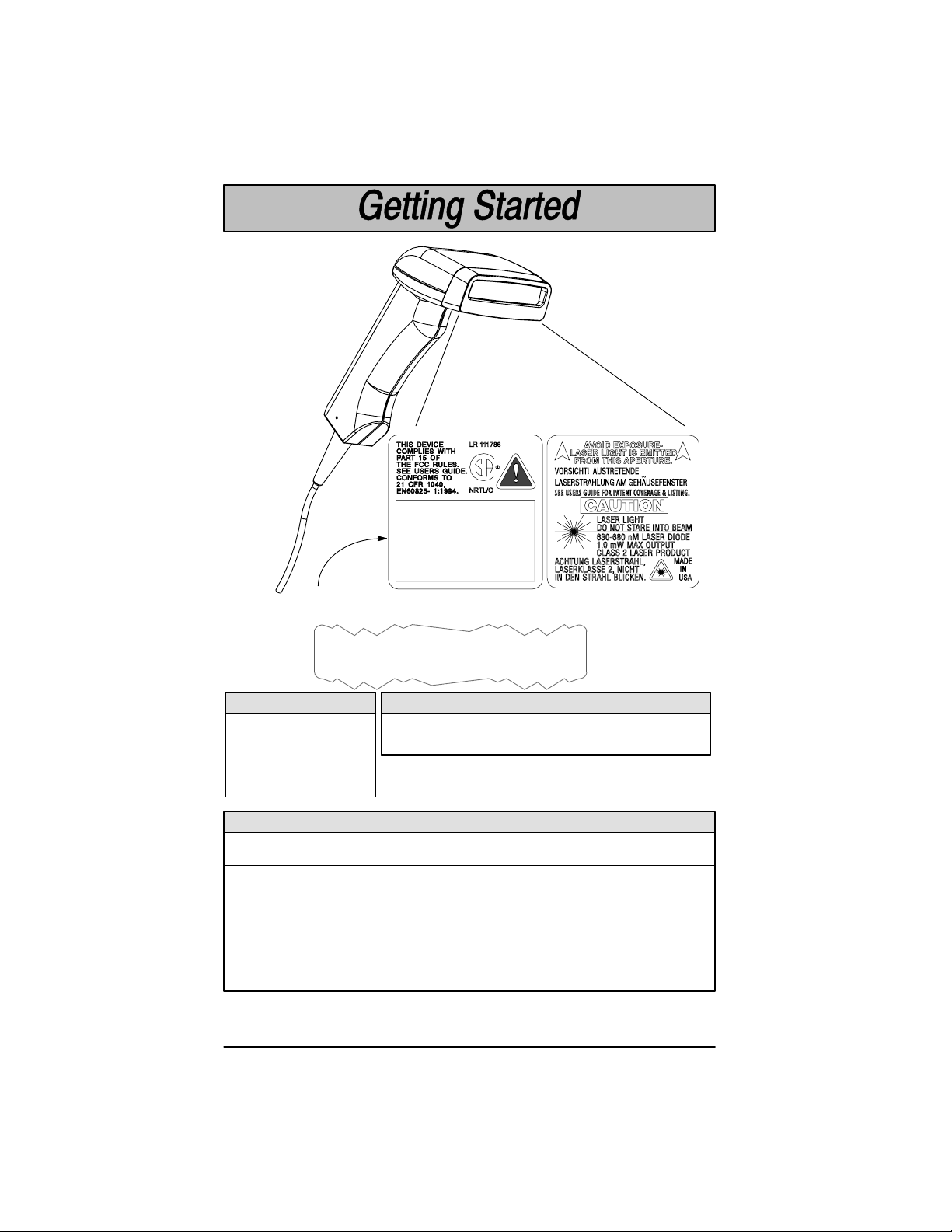
Scanner Identification
Manufactured Month/Year
Model Number 5X00/A-12
Serial Number 12345
Rev = 1.1=B=A
SCANTEAM 5700 Identification Label
Model Number 5X00/A–12
➌➋
➊
Engine Type
A = Increased
Performance
➊➋
AutoTrigger Option
0 = Hands Free AutoTrigger Feature Not Included
1 = Hands Free AutoTrigger Feature Included
HD = High Density
ALR = Advanced Long
Range
Interface Option
IBM
Option
0*
1
2
3
4**
* Operates only from +5V power source for 5700/A.
** Operates only from either +5 or +12V power.
OCIA
4683
OCR
DDDD
1–2
➌
Bar Image
Laser Out
D
D
SCANTEAM 5700 User’s Guide
Wand
Emulation
D
D
TTL
RS–232
D
D
True
RS–232
D
Keyboard
Wedge
Various
Various
DEC Only
RS–232
Wedge
D
Page 11
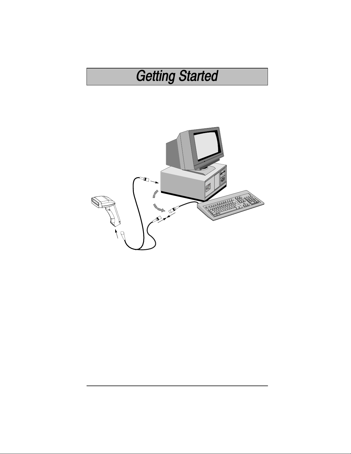
Connecting the Scanner
Install the scanner by following the steps shown below:
➊ Turn off the power to the host system.
➋ Connect the interface cable to the scanner and to the terminal/computer.
3
Disconnect
2
1
Keyboard Wedge Interface Example
(Cable, Keyboard, and Terminal will vary.)
➌ Turn on the power to the host system.
➍ Program your scanner to work with your terminal or computer by scanning
the Terminal Set–Up Codes. Either scan the Plug and Play codes (Pages
1–7 to 1–10) or use the Supported Terminal list (Pages 1–11 to 1–12) to
determine your terminal’s Terminal ID.
With Plug and Play programming, you connect the scanner and scan only one
bar code to program the scanner to work with a designated interface, including
any required prefixes and suffixes.
➎ To determine if your scanner is set up correctly, scan one of the sample bar
codes on the back cover of this guide.
SCANTEAM 5700 User’s Guide
1–3
Page 12

In. Cm.
Typical Performance at 20°C for
9.65 24.511
SCANTEAM 5700/A
19.3”
5 mil
2.5
3.5
7.5 mil
2
1
1.5
3.5
4
In.
Cm.0025.08410.2615.2820.31025.41230.51435.6.1640.61845.72050.82255.9246126662871.13076.23281.3
7
13 mil
40 mil
14
18
55 mil
20mil
Typical Depth of Field in Inches/Centimeters
9.65 24.511
26
31
1–4
SCANTEAM 5700 User’s Guide
Page 13

Typical Performance at 20°C for
SCANTEAM 5700/HD
2.8”
2.0” 3”
In. Cm.
2 5.08
1 2.54
00
In.
Cm.00
3 mil
1.0 2.5
.5
.5
1.0
1
2.54
5.08
2
5 mil
7.5 mil
10 mil
3
7.62410.16
4.0
4.5
13 mil
Typical Depth of Field in Inches/Centimeters
12.7
1 2.54
2 5.08
5.5.5
6.0
5
6
15.24
SCANTEAM 5700 User’s Guide
1–5
Page 14

Typical Performance at 20°C for
SCANTEAM 5700ALR
In. Cm.
41
104.1
30
76.2
20
50.8
10
25.4
00
25.410
15 mil
22
43
30 mil
40
25
In.
0 90 180 270 360
Cm.
30 60 120 150 210 240 300 330
0 228.6 457.2 685.8 914.476.2 152.4 304.8 381.0 533.4 609.6 762.0 838.2
55 mil
88
99
123
100 mil
322
Typical Depth of Field in Inches/Centimeters
70 mil retroreflective – 68” (172.7 cm) – 13.5’ (411.5 cm)
100 mil retroreflective – 82” (208.3 cm) – 17.5’ (533.4 cm)
50.820
76.230
104.141
1–6
SCANTEAM 5700 User’s Guide
Page 15

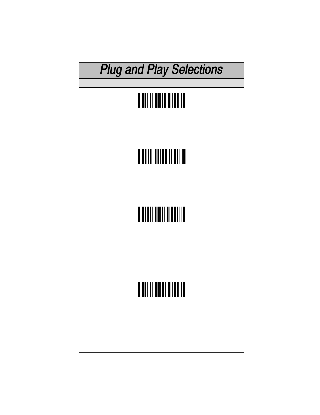
IBM PC, Wand Emulation Interface
IBM PC AT and Compatibles Interface (Default)
(also PS/2 30-286, 50, 55SX, 60, 70, 70-061, 70-121, 80)
IBM PS/2 and Compatibles Interface
( for PS/2 25, 30 models)
IBM PC XT and Compatibles Interface
These bar codes also program a carriage return (CR) suffix.
Wand Emulation (Code 39 Format) Interface
Wand Emulation (Same Code Format) Interface [
[ Supports Code 39, UPC, EAN, Code 128, Interleaved 2 of 5, and Codabar.
All other codes output as Code 39.
These bar codes also program the following parameters:
Programmable Option Setting
Transmission Rate 20 inches per second
Output Polarity Black High
SCANTEAM 5700 User’s Guide
1–7
Page 16

IBM 4683 Interface
IBM 4683 Port 5B Interface
IBM 4683 Port 9B HHBCR–1 Interface
IBM 4683 Port 9B HHBCR–2 Interface
IBM 4683 Port 17 Interface
These bar codes also program the following parameters:
Symbology Suffix Symbology Prefix
EAN 8 0C Code 39 00 0A 0B
EAN 13 16 I 2 of 5 00 0D 0B
UPC A 0D Code 128 00 18 0B
UPC E 0A
1–8
SCANTEAM 5700 User’s Guide
Page 17
OCIA Interface
Spectra-Physics OCIA Interface
The bar code above also programs the following parameters:
Symbology Suffix Symbology Prefix
EAN 8 06 06 UPC A 01
EAN 13 06 UPC E 05
NCR OCIA Short Form Format (Eight Bit) Interface
The bar code above also programs the following parameters:
Symbology Suffix Symbology Prefix
EAN 8 0F 0F UPC A 0A
EAN 13 0F UPC E 0E
NCR OCIA Long Form Format (Nine Bit) Interface
The bar code above also programs the following parameters:
Symbology Suffix Symbology Prefix
EAN 8 46 46 Code 39 42 31
EAN 13 46 I 2 of 5 42 32
UPC A 41 Code 128 42 33
UPC E 45
Nixdorf OCIA Interface
This bar code above also programs the following parameters:
Symbology Prefix
EAN/UPC with Addenda 44 4B
Code 39 44 49
I 2 of 5 44 48
2 of 5 44 47
Code 128 44 4A
SCANTEAM 5700 User’s Guide
1–9
Page 18
OCR, RS232 Interface
Fujitsu OCR Interface
The bar code above also programs the following parameters:
Symbology Suffix Symbology Prefix
EAN 8 17 UPC A 17
EAN 13 17 UPC E 17
I 2 of 5 03 (Application Dependent)
IBM OCR (Port 21) Interface
The bar code above also programs the following parameters:
Symbology Suffix Symbology Prefix
EAN 8 0C UPC A 0D
EAN 13 16 UPC E 0A
Code 128 1D
RS-232 Interface
The bar code above also programs the following parameters:
Programmable Option Setting
Baud Rate 9600 bits per second
Parity even
Data Format 7 data bits, parity bit, 1 stop bit
(8 Bit Data)
End of “Plug and Play” programming...
1–10
SCANTEAM 5700 User’s Guide
Page 19
If your terminal is not one of the Plug and Play options, you must program one
of the terminals listed below. To program the terminal interface, scan the
Program Terminal Interface bar code below, then scan the appropriate two digit
Terminal I.D. code from the Programming Chart on the inside back cover of this
manual.
Program Terminal Interface
Supported Terminals
Terminal Model(s) Terminal I.D.
ADI 1496 72
Apple Desktop Bus ADB MAC Classic, SE SE30, II (All) 49
Bull BDS–7 (HDS–7) 35
Burroughs B25 75
Decision Data DDC3596, 3597 30
DEC VT–220, 320, 330, 340 420 04
Esprit 200, 400 05
Falco 5220 47
Heath Zenith PC 90
HP 700/44, 700/92, 700/94, 20
700/96, 700/98
HP 700/60 79
HP Vectra QS–16 03
IBM PC XT 01
IBM PS/2 25, 30 02
IBM AT, PS/2 30–286, 50, 55SX, 03*
60, 70, 70–061, 70–121, 80
IBM 4683, 4684 51
IBM 102 Key 3151, 3161, 3162, 3163, 3191, 06
3192, 3196, 3197, 3471, 3472,
3476, 3477
IBM 122 Key 3179–1, 3191, 3192, 3471, 07
3472, 3194
IBM 122 Key 3196, 3197, 3476, 3477, 08
3486, 3488, 3482
IBM 122 Key 3180 24
* = Default
SCANTEAM 5700 User’s Guide
1–11
Page 20

Supported Terminals
Terminal Model(s) Terminal I.D.
ICL 300 77
IDEAS 08
ITT 9271 07
Lee Data IIS 07
Link MC–5 18
Mac 49
OCIA 52
OCR 53
Olivetti M19, M24, M28, M200 01
Olivetti 240, 250, 290, 380, P500 03
Qume ANSI QVT 61, 62, 70, 191, 321, 322 82
Qume ASCII QVT 31, 51, 61, 62, 70, 191 74
Qume Enhanced PC QVT 61, 62, 70, 82, 191, Qx15 38
RS232 True 00
RS232 TTL 00
Serial Wedge 50
Siemens 9758 (German Only) 34
Stratus V103 14
Televideo 955, 965 36
Telex 88 Key 078A, 078, 79, 80, 191, 196, 25
1191, 1192, 1471, 1472, 1476
Telex 102 Key 078A, 078, 79, 80, 191, 196, 45
1191, 1192, 1471, 1472, 1476
Telex 122 Key 078A, 078, 79, 80, 191, 196, 46
1191, 1192, 1471, 1472, 1476
Wand Emulation 61
WYSE WY–30 13
WYSE WY–85/185 16
WYSE ANSI WY 60, 120, 150, 160 15
WYSE ASCII WY 60, 120, 150, 160, 99GT 14
WYSE Enhanced PC WY 60, 120, 150, 160 18
1–12
SCANTEAM 5700 User’s Guide
Page 21
Reset Factory Settings
Scanning the Factory Default Settings bar code resets the scanner to the
original factory settings, clearing any programming changes you may have
made.
Factory Default Settings
Status Check
Scan the Show Software Revision bar code to transmit the software revision
level to the host terminal. The software revision will be printed out as
“WA34310XXX.” (The “X’s” will vary according to the firmware ID.)
Show Software Revision
Quick Suffix Selections
If your application requires it, scan the Program Carriage Return Suffix bar
code to program a carriage return (CR) suffix for all enabled bar code
symbologies. Scanning this bar code clears all previously programmed
prefixes and suffixes.
Scan the Clear Bar Code Suffix bar code to disable (or clear) all previously
programmed prefixes and suffixes (e.g., the carriage return suffix).
Program Carriage Return Suffix
Clear Bar Code Suffix
SCANTEAM 5700 User’s Guide
1–13
Page 22
Scanner models 5700–X1 and 5700/X–X2 support the dual interface option
allowing you to connect to two different terminals by switching interface cables.
This option supports interfaces common to portable data terminals.
Dual Interface Programming Instructions
To program the scanner for secondary interface, follow the steps below. (Dual
Interface single scan programming codes are shown on the following
pages.)
➊ While the scanner is connected to the primary terminal interface, scan one
of the single bar codes on 1–15 to enable the secondary interface.
➋ Disconnect the primary interface cable from the scanner and attach the
secondary interface cable.
➌ Attach the secondary interface cable to the secondary terminal and power
up the terminal.
➍ Program the desired programmable selections for the secondary interface.
Dual Interface Programming Notes:
• To change the secondary interface from one selection to another (e.g., from
HHLC to RS-232), the scanner must be reconnected to the primary
interface, and then reprogrammed for the new secondary interface.
Connect the scanner to the primary interface cable. Follow steps 1–4
above.
• Scanning “Plug and Play” bar codes (single scan terminal selection bar
codes), or changing the terminal type does not affect Dual Interface settings.
• RS-232 programmable selections are used by both the primary and
secondary interfaces. Changing an RS-232 parameter (e.g., baud rate or
parity), while in primary or secondary mode will affect both interfaces.
• The Switch Power feature is a low power sleep mode which is automatically
enabled when the secondary interface cable is attached and the unit is
programmed for a second interface. The option is enabled when the unit is
shipped.
Note: Dual Interface selection is not available if the scanner is programmed for
an HP terminal with a Terminal I.D. of 20 or 79, or for a WYSE terminal with a
Terminal I.D. of 13–18.
[ Note: Section 2 contains information about Dual Interface Prefix/Suffix
programming.
1–14
SCANTEAM 5700 User’s Guide
Page 23
Code 39 Wand Emulation Selection
✱ Code 39 Wand Emulation Selection
Same Code Wand Emulation Selection
Same Code Wand Emulation Selection [
RS-232 Selection
RS-232 Selection
Laser Emulation Selection
Laser Emulation Selection
Note: 5700–X3 units do not support Dual Interface.
[ Supports Code 39, UPC, EAN, Code 128, Interleaved 2 of 5, and Codabar.
All other codes output as Code 39.
SCANTEAM 5700 User’s Guide
1–15
Page 24
Dual Interface Enable/Disable Selection
Dual Interface Disable Selection lets you temporarily disable the dual interface
selection, while retaining your secondary interface setup in memory. If you want
to enable the secondary interface again, scan the Enable Dual Interface bar
code below.
Enable
✱ Disable
Switched Power Mode Selections
When this feature is enabled, the unit consumes less than 50 uA from its power
line when the trigger is not pulled. When the trigger is pulled, it consumes normal
power. This feature is used for battery powered devices to save power. If power
savings is not an issue and speed is, disable this feature for better performance.
✱ Switched Power (Low Power) Mode
Constant Power Mode
Laser Emulation Power Up Delay Selection
Scan the Laser Emulation Power Up Delay bar code to delay full power up. This
allows the PDT terminal to power up on scanner trigger. The PDT powers down
between scans, greatly extending battery life.
Scan two of the Numeric Bar Codes on the Programming Chart (inside back
cover) to set the delay to any value between 00 and 99. 00–99 is the multiplier
(x5ms).
1–16
Power Up Delay
SCANTEAM 5700 User’s Guide
Page 25

Section 2 Serial Interface Menu
Introduction
Use this chapter to program the output parameters for the Hand-Held Laser
Scanner.
This programming section contains the following menuing selections:
• Prefix and Suffix
• Output
• Serial Communication (RS-232)
• Data Formatter
SCANTEAM 5700 User’s Guide
2–1
Page 26

Primary Interface Prefix and Suffix
The scanner transmits a decoded message after every successful bar code
read. Prefix and Suffix characters are data characters you may assign to be sent
before and after the transmitted bar code data.
Transmitted data frame –>
Characters for the Prefix and Suffix are selected by their hexadecimal ASCII
value, up to 12 characters each. Prefix and Suffix characters may be sent for a
specific symbology, or may be sent with all bar code scans.
Default Prefix = none. Default Suffix = none.
Programming Steps to Add a Primary Interface Prefix / Suffix:
➊ To add a Prefix, scan the Add Primary Prefix programming bar code.
To add a Suffix, scan the Add Primary Suffix programming bar code.
➋ Refer to the Symbology Chart (page 2–7) to find the Hex value that
represents the symbology(s) you want transmitted with one or more
Prefixes or Suffixes. Scan the two digits on the Programming Chart (on
the inside of the back cover of this menu).
➌ Refer to the Hex ASCII Chart (page 2–7) to find the Hex value that
represents the ASCII characters you wish to transmit with the bar code
data. Use the Programming Chart (inside back cover) to scan the
alphanumeric combination that represents the ASCII characters.
➍ To complete Prefix / Suffix programming, scan either:
H Save Current Prefix or Suffix Changes[ programming bar code.
This exits, saving the Prefix / Suffix selections you just assigned.
H Discard Current Prefix or Suffix Changes programming bar
code. This exits without changing the Prefix / Suffix.
Prefix SuffixBar Code Message
[ You may also start scanning bar codes; your Prefix / Suffix selections will be saved.
Programming Steps to Clear (or Delete) One Prefix / Suffix Entry:
➊ To clear the Prefix entry for a specific symbology, scan the Clear One
Primary Prefix programming bar code.
To clear the Suffix entry for a specific symbology, scan the Clear One
Primary Suffix programming bar code.
➋ Refer to the Symbology Chart to find the Hex value representing the
symbology’s entry you want cleared. Scan the two digits on the
Programming Chart (on the inside of the back cover of this menu).
➌ You don’t need to scan Save Current ... Changes or Discard Current
... Changes programming bar codes to complete programming.
Other Programming Selections: Scanning the Clear All Primary Prefixes or
Clear All Primary Suffixes bar code deletes all
selections. You don’t need to scan the Save Current ... Changes or Discard
Current ... Changes programming bar code to complete programming.
Note: Prefix / Suffix programming examples may be found on page 2–6.
2–2
SCANTEAM 5700 User’s Guide
Primary Prefix or Suffix
Page 27
Primary Interface Prefix Selection
Add Primary Prefix ]
Clear One Primary Prefix ]
Clear All Primary Prefixes
Primary Interface Suffix Selection
Add Primary Suffix ]
Clear One Primary Suffix ]
Clear All Primary Suffixes
Exit Selection for Prefix / Suffix
Save Current Prefix or Suffix Changes
Discard Current Prefix or Suffix Changes
] One or more two-digit numbers are required after scanning this programming bar
code. Please scan your selection on the Programming Chart (inside back cover).
SCANTEAM 5700 User’s Guide
2–3
Page 28

Secondary (Dual) Interface Prefix and Suffix
The scanner will transmit a decoded message after every successful bar code
read. Prefix and Suffix characters are data characters you may assign to be sent
before and after the transmitted bar code data.
Transmitted data frame –>
Characters for the Prefix and Suffix are selected by their hexadecimal ASCII
value, up to 12 characters each. Prefix and Suffix characters may be sent for a
specific symbology, or may be sent with all bar code scans.
Default Prefix = none. Default Suffix = none.
Programming Steps to Add a Secondary (Dual) Interface Prefix / Suffix:
➊ To add a Prefix, scan the Add Secondary Prefix programming bar code.
To add a Suffix, scan the Add Secondary Suffix programming bar code.
➋ Refer to the Symbology Chart (page 2–7) to find the Hex value that
represents the symbology(s) you want transmitted with one or more
Prefixes or Suffixes. Scan the two digits on the Programming Chart (on
the inside of the back cover of this menu).
➌ Refer to the Hex ASCII Chart (page 2–7) to find the Hex value that
represents the ASCII characters you wish to transmit with the bar code
data. Use the Programming Chart (inside back cover) to scan the
alphanumeric combination that represents the ASCII characters.
➍ To complete Prefix / Suffix programming, scan either:
H Save Current Prefix or Suffix Changes[ programming bar code.
This exits, saving the Prefix / Suffix selections you just assigned.
H Discard Current Prefix or Suffix Changes programming bar
code. This exits without changing the Prefix / Suffix.
Prefix SuffixBar Code Message
[ You may also start scanning bar codes; your Prefix / Suffix selections will be saved.
Programming Steps to Clear (or Delete) One Prefix / Suffix Entry:
➊ To clear the Prefix entry for a specific symbology, scan the Clear One
Secondary Prefix programming bar code.
To clear the Suffix entry for a specific symbology, scan the Clear One
Secondary Suffix programming bar code.
➋ Refer to the Symbology Chart to find the Hex value representing the
symbology’s entry you want cleared. Scan the two digits on the
Programming Chart (on the inside of the back cover of this menu).
➌ You don’t need to scan Save Current ... Changes or Discard Current
... Changes programming bar codes to complete programming.
Other Programming Selections: Scanning the Clear All Secondary Prefixes
or Clear All Secondary Suffixes bar code deletes all
selections. You don’t need to scan the Save Current ... Changes or Discard
Current ... Changes programming bar code to complete programming.
Note: Prefix / Suffix programming examples may be found on page 2–6.
2–4
SCANTEAM 5700 User’s Guide
Secondary Prefix or Suffix
Page 29
Secondary Interface Prefix Selection
Add Secondary Prefix ]
Clear One Secondary Prefix ]
Clear All Secondary Prefixes
Secondary Interface Suffix Selection
Add Secondary Suffix ]
Clear One Secondary Suffix ]
Clear All Secondary Suffixes
Exit Selection for Prefix / Suffix
Save Current Prefix or Suffix Changes
Discard Current Prefix or Suffix Changes
] One or more two-digit numbers are required after scanning this programming bar
code. Scan your selection on the Programming Chart (inside back cover).
SCANTEAM 5700 User’s Guide
2–5
Page 30

Prefix and Suffix Examples
Example 1: Add Suffix for Specific Symbology
You want to send a CR (carriage return) Suffix for UPC only.
H Scan the Add Suffix Suffix Selection bar code.
H The Symbology Chart indicates that the Hex value of UPC is “63”. Scan
6 and 3 on the Programming Chart (inside back cover).
H A “CR” is equivalent to “0D” (see the Hex ASCII Chart). Scan 0 and D
on the Programming Chart.
H Scan the Save Current Suffix Changes Exit Selection bar code.
Example 2: Add Suffix for ALL Symbologies
You want to send a CR (carriage return) Suffix for all symbologies.
H Scan the Add Suffix Suffix Selection bar code.
H The Symbology Chart indicates that the Hex value for All Symbologies
is “99”. Scan 9 and 9 on the Programming Chart.
H A “CR” is equivalent to “0D”. Scan 0 and D on the Programming Chart.
H Scan the Save Current Suffix Changes Exit Selection bar code.
Example 3: Add Prefix for Specific Symbology / Suffix for ALL Symbologies
You want to send a HT (tab) Prefix for UPC only and a CR / LF (carriage
return / line feed) Suffix for all symbologies.
H Scan the Add Prefix Prefix Selection bar code.
H The Symbology Chart indicates that the Hex value of UPC is “63”. Scan
6 and 3 on the Programming Chart.
H An “HT” is equivalent to “09”. Scan 0 and 9 on the Programming Chart.
H Scan the Add Suffix Suffix Selection bar code.
H The Symbology Chart indicates that the Hex value for All Symbologies
is “99”. Scan 9 and 9 on the Programming Chart.
H A “CR” is equivalent to “0D” and an “LF” is “0A”. Scan 0, D, 0, and A on
the Programming Chart.
H Scan the Save Current Prefix / Suffix Changes Exit Selection bar
code.
Example 4: To Clear a Specific Prefix Entry
You’ve programmed the scanner to send a CR / LF (carriage return / line feed)
Prefix for all symbologies (Hex value, 99). This is one Prefix entry. You’ve also
programmed a “#” Prefix for UPC (Hex, 63). You decide that you want to clear
the UPC entry, but not the Prefix entry for all symbologies.
H Scan the Clear Specific Prefix Prefix Selection bar code.
H The Symbology Chart indicates that the Hex value for UPC is “63”. Scan
6 and 3 on the Programming Chart.
2–6
SCANTEAM 5700 User’s Guide
Page 31

Symbology Chart
Symbology
Codabar
Code 39
UPC
EAN
Interleaved 2 of 5
Code 2 of 5
MSI
Code
[
ID
a
b
c
d
e
f
g
Hex
Value
61
62
63
64
65
66
67
Symbology
Code 11
Code 93
Code 128
Matrix 2 of 5
Plessey
All Symbologies
(Prefix/Suffix Programming only.)
Code
ID [
h
i
j
m
n
Hex to ASCII Conversion Chart
ASCII Hex ASCII Hex ASCII HexASCII Hex ASCII Hex ASCII Hex ASCII Hex ASCII Hex
NUL
00
DLE
10
SP
20
0
30
@
40
P
50
‘
SOH
STX
ETX
EOT
ENQ
ACK
BEL
BS
HT
LF
VT
FF
CR
SO
SI
01
02
03
04
05
06
07
08
09
0A
0B
0C
0D
0E
0F
DC1
DC2
DC3
DC4
NAK
SYN
ETB
CAN
EM
SUB
ESC
FS
GS
RS
US
11
12
13
14
15
16
17
18
19
1A
1B
1C
1D
1E
1F
!
”
#
$
%
&
’
(
)
*
+
,
–
.
/
21
22
23
24
25
26
27
28
29
2A
2B
2C
2D
2E
2F
1
31
A
41
Q
2
32
B
3
33
4
34
5
35
6
36
7
37
8
38
9
39
:
3A
;
3B
<
3C
=
3D
>
3E
?
3F
42
C
43
D
44
E
45
F
46
G
47
H
48
I
49
J
4A
K
4B
L
4C
M
4D
N
4E
O
4F
R
S
T
U
V
W
X
Y
Z
[
\
]
^
_
51
52
53
54
55
56
57
58
59
5A
5B
5C
5D
5E
5F
a
b
c
d
e
f
g
h
i
j
k
l
m
n
o
60
61
62
63
64
65
66
67
68
69
6A
6B
6C
6D
6E
6F
Hex
Value
p
q
r
s
t
u
v
w
x
y
z
{
|
}
~
DEL
68
69
6A
6D
6E
99
70
71
72
73
74
75
76
77
78
79
7A
7B
7C
7D
7E
7F
Note: Prefix / Suffix entries for specific symbologies override the universal (All
Symbologies, 99) entry.
Note: Adding a Prefix or a Suffix appends that Prefix / Suffix to any existing
entries for the symbology(s) you’ve chosen. For example, if you’ve already
programmed and saved a CR / LF (carriage return / line feed) and add a “#”
Prefix, the ”#” will be sent after the CR / LF.
If you add a Prefix / Suffix but want existing entries cleared, you’ll need to use
the Clear Specific Prefix / Suffix programming selection first. Then use the
Add Prefix / Suffix programming selection to program your new Prefix / Suffix.
SCANTEAM 5700 User’s Guide
2–7
Page 32

✱ Default All Output Settings ✱
Beeper Volume Selection
Off
Medium
Low
✱ High
Output Delays Selection
This selection provides control of the time delays between data output by the
scanner to the host terminal. The actual delay is 5 milliseconds multiplied by the
programmed value (00 – 99). Default = 00.
Intercharacter Delay is the time delay between data characters output by the
scanner to the host terminal.
Interfunction Delay is the time delay between function (key) codes output by
the scanner to the host terminal.
Intermessage Delay is the time delay between data messages or records
output by the scanner to the host terminal.
Example: You need a 45 millisecond delay. Scan the Intercharacter Delay
bar code. Then scan “0” and “9” on the Programming Chart (09 x 5ms = 45 ms).
Intercharacter Delay (x5mS) ]
Interfunction Delay (x5mS) ]
] A two-digit number is required after scanning this programming bar code.
Please scan your selection on the Programming Chart (inside back cover).
2–8
SCANTEAM 5700 User’s Guide
Intermessage Delay (x5mS) ]
Page 33

Reread Delay Selection
This selection allows you to set a time period that must pass before the scanner
can read the same bar code again. Setting a reread delay protects against
accidental rereads of the same bar code. Longer delays are effective in
minimizing accidental rereads at POS (point of sale) terminals. Use shorter
delays in applications where repetitive bar code scanning is required.
✱ Low (175 milliseconds)
High (1.0 second)
Medium (450 milliseconds)
Extra High (2.0 seconds)
Good Read Delay Selection
This selection allows you to set a time period that must pass before the scanner
can read another bar code. Some terminals require a slower read rate. By
setting a good read delay, you can ensure a good read.
None
✱
Medium (1.0 second)
Low (500 milliseconds)
High (1.5 second)
Laser Voting Selection
When Laser Voting is enabled, the scanner requires three (3) identical,
consecutive scans before the bar code data will be accepted and transmitted to
the terminal. When this selection is disabled, the bar code data will be
transmitted following one (1) valid scan.
Enable
SCANTEAM 5700 User’s Guide
✱ Disable
2–9
Page 34

Buffered Scans Selection
When enabled, this selection allows the scanner to accept a second scan while
the current scan is transmitted to the host terminal (buffering of scanned data).
When disabled, the scanner cannot accept additional scans until the current
scan is transmitted to the host. Default = Enable.
✱ Enable
Disable
Code I.D. Transmit Selection
This allows you to enable or disable transmission of a Code I.D. before the
decoded bar code symbology. (See the Symbology Chart on page 2–7 for the
single character code that identifies each symbology.)
Enable
✱ Disable
AIM I.D. Transmit Selection
This selection allows you to enable or disable transmission of an AIM I.D. before
the decoded bar code symbology. (See AIM Guidelines on Symbology
Identifiers for more information on the AIM symbology ID characters.) Default
= Disable.
Enable
✱ Disable
Function Code Transmit Selection
When this selection is enabled, and function codes are contained within the
scanned data, the scanner transmits the key code (which corresponds to the
decoded ASCII function code) to the terminal. ASCII function codes are
represented by the HEX values 00–1F. (Charts of these function codes are
shown in Section 6, Supported Interface Keys.)
Disable
2–10
✱ Enable
SCANTEAM 5700 User’s Guide
Page 35

✱ Default All Serial Communication Settings ✱
CTS Check Selection
This selection allows you to select the software programming feature that checks
for a CTS signal, if your application does not have a CTS I/O line. Default =
Disable.
Enable
✱ Disable
Baud Rate Selection
This selection sets the baud rate from 300 bits per second to 38,400 bits per
second. Programming baud rate causes the data to be sent at the specified rate.
The host terminal must be set up for the same baud rate as the scanner, to ensure
reliable communication. Default = 9600 bps.
300
1200
4800
600
2400
✱ 9600
19200
SCANTEAM 5700 User’s Guide
38400
2–11
Page 36

RS-232 Word Length Selection
This selection allows you to set the RS-232 word length at seven or eight bits of
data per character. The number of start and stop bits is fixed at one each. If an
application requires only ASCII Hex characters 0 through 7F decimal (text, digits,
and punctuation), select 7 data bits. For applications requiring use of the full
ASCII set, select 8 data bits per character.
✱ 7 Data, 1 Stop
7 Data, 2 Stop
8 Data, 1 Stop
Parity Selection
This selection provides a means of checking character bit patterns for validity.
The scanner can be configured to operate under Even, Odd, Mark / None, or
Space parity options. The host terminal must be set up for the same parity as
the scanner, to ensure reliable communication.
None
Mark
Space
2–12
Odd
SCANTEAM 5700 User’s Guide
✱ Even
Page 37

Protocol Selection
This selection allows you to program the scanner for the protocol required by
your application. The protocol is a set of rules concerning the exchange of data
between serially communicating devices. The scanner supports Record,
Xon / Xoff, and Ack / Nak protocols when receiving data from an RS-232 device.
✱
Record
Xon / Xoff
Ack / Nak
Serial Wedge Output Selection
This selection allows you to select the serial output direction required by your
application. P1 and P2 are serial wedge designations printed on the serial wedge
cable. Usually, one goes to the host and one goes to the terminal, depending on
your specific application and the serial wedge cable.
Note: Serial Wedge programming is for scanner model –X3 only! The scanner
must also be in Serial Wedge mode (Terminal I.D. 50).
✱ To P1
To P2
To P1 and P2
SCANTEAM 5700 User’s Guide
2–13
Page 38

Data Format Editor
This selection provides editing of all input (scanned) data. All Industrial and
Retail symbologies can be formatted. You may scan the Clear Data Format bar
code if you are certain you want to delete or clear all formats.
To make Data Format Editor selections, you must know the terminal type,
code I.D., code length, and editor commands your application requires.
Use the Alpha-numeric bar codes (inside back cover) to scan these
Use the Data Format Editor by following the steps below:
➊ Scan the Enter Data Format bar code.
➋ Terminal Type
Scan two bar codes that represent the terminal type (00-99[, see page
1–11 for Terminal I.D. list.)
➌ Code I.D.
Refer to the Symbology chart (page 2–7), then scan two bar codes from
the “Hex Value” column that represent the Code I.D. of the symbology you
want formatted. (“All Symbologies” – hex value 99 – is not supported by
Data Formatter.)
➍ Length
Scan two numeric bar codes (inside back cover) for the bar code length you
require (00-99[). Be sure to include spaces.
➎ Editor Command Sequences
Refer to the Format Editor Commands chart (page 2–16). Scan two bar
codes that represent the command you need.
➏ End Format (FF)
Scan “F” twice to end Data Format Editor programming.
options.
[ 99 is the Universal number, indicating all terminals and all code lengths.
2–14
SCANTEAM 5700 User’s Guide
Page 39

Status Check
Scan the Show Formats bar code to transmit the existing Data Format Editor
formats. One format per line will be printed out.
Show Formats
Require Data Format
When disabled, the bar code data will be output to the host as scanned (including
prefixes and suffixes). When enabled, all input data must conform to an edited
format or the scanner will not transmit the input data to the host device.
Enable
✱ Disable
Data Format Editor
See pages 2–14 and 2–16 through 2–17 for a description of this selection and
examples.
Enter Data Format
Clear All Data Formats
SCANTEAM 5700 User’s Guide
2–15
Page 40

Format Editor Commands Chart
Send Commands
F1 Send all characters followed by “XX” key or function code, starting from
current cursor position. Syntax = F1XX (XX = HEX ASCII character or
function code 00–FE HEX).
F2 Send “NN” characters followed by “XX” key or function code, starting from
current cursor position. Syntax = F2NNXX (NN = number of characters
00–99 DEC, XX = HEX ASCII character or function code 00–EF HEX).
F3 Send up to but not including “SS” character (Search and Send) starting from
current cursor position, leaving cursor pointing to “SS” character followed
by “XX” key or function code. Syntax = F3SSXX (SS = HEX ASCII
Character 00–7F HEX, XX = HEX ASCII character 00–7F HEX).
F4 Send “XX” character “NN” times (Insert) leaving cursor in current cursor
position. Syntax = F4XXNN (XX = HEX ASCII character 00–7F HEX, NN
= number of characters 00–99 DEC).
Move Commands
F5 Move cursor ahead “NN” characters from current cursor position.
Syntax = F5NN (NN = number of characters 00–99 DEC).
F6 Move cursor back “NN” characters from current cursor position.
Syntax = F6NN (NN = number of characters 00–99 DEC).
F7 Move cursor to the beginning of the data string. Syntax = F7.
Search Commands
F8 Search ahead for “XX” character from current cursor position, leaving cursor
pointing to “XX” character. Syntax = F8XX (XX = HEX ASCII character
00–7F).
F9 Search back for “XX” character from current cursor position, leaving cursor
pointing to “XX” character. Syntax = F9XX (XX = HEX ASCII character
00–7F).
Miscellaneous Commands
FA Leading zero suppress on. Suppress leading zeroes from current cursor
position until first non–zero character. Syntax = FA.
FB Suppress “XX” character(s) (up to three) starting from current cursor
position until suppress disable command “FC” or end of format. Syntax =
FBXXFB, FBXXXXFB, FBXXXXXXFB (XX = ASCII character 00–7F).
FC Disable suppress filter and clear all suppressed characters. Syntax = FC.
FE Compare character in current cursor position to the character “XX.” If
characters are equal, increment cursor. If characters are not equal, no
format match. Syntax = FEXX (XX = HEX ASCII character 00 –7F).
2–16
SCANTEAM 5700 User’s Guide
Page 41

Data Formatter Example
You are using an IBM PC AT and are scanning a UPC A bar code with a five digit
addenda (shown below). The bar code has a total of 18 characters, including the
number system, the check digits, and a space between the main bar code data
and the addenda bar code data.
UPC A with 5 digit addenda
56098
0 12345 67890 5
For your application, you don’t want the space between the main bar code data
and the addenda bar code data transmitted. You also want the bar code data
followed by a carriage return (CR).
Refer to the Format Editor Commands Chart on page 2–16 to format the
following example. The programming bar codes on pages 2–15, and the
alpha-numeric bar codes on the inside back cover are used to program the data
formatter.
H Scan the Enter Data Format bar code (page 2–15).
H Scan the 03 bar codes for PC AT Terminal Type.
H Scan the 63 bar codes, the Hex value for UPC symbology.
H Scan the 18 bar codes for the bar code length.
The following are the Editor Command Sequences:
H Scan the FB (suppress characters command) bar codes, scan 20 (the Hex
value for a space), and then scan FB to frame (complete) the command.
H Scan the F7 bar codes to move the cursor back to the beginning of the bar
code data.
H Scan the F1 and 0D bar codes to send all the characters followed by a
carriage return (CR= 0D in Hex value).
H Scan the FF bar codes to end Format Editor selection.
SCANTEAM 5700 User’s Guide
2–17
Page 42

2–18
SCANTEAM 5700 User’s Guide
Page 43

Introduction
Use this chapter to program the Hand-Held Laser Scanner for General Operating
features.
This programming section contains the following menuing selections:
• Laser Options
• Wand Emulation
• Country Code
• Keyboard
SCANTEAM 5700 User’s Guide
3–1
Page 44
Marker Beam Selection
When enabled, the scanner shows a marker or locator beam before the red scan
line opens across a bar code and the scanning process begins. The marker
beam, emitted by centering the optical scan mirror, appears as a bright spot of
illumination that serves as an aiming guide when bar code targets are at a
distance from the scanner. Note: Applies only to the 5700ALR product.
On
✱ Off
AutoTrigger Selection [
When enabled, this programming selection allows auto-triggering with the
optional Scan Stand. The Scan Stand provides hands-free operation in any
application where a great number of bar code entries is required. Note:
Does not apply to the 5700ALR product.
Note: The scanner must be ordered with the AutoTrigger configuration.
✱ Enable
Disable
[ This programming feature is available only if you have purchased scanner
models 5700/A–1X (refer to Sales Configuration Worksheet).
3–2
SCANTEAM 5700 User’s Guide
Page 45
Transmission Rate Selection
This programming selection sets the transmission rate from 10 ips (inches per
second) to 300 ips if the scanner is in Wand Emulation mode. Programming the
transmission rate causes the data to be sent at the specified rate. The
programmed transmission rate must be compatible with the device receiving the
bar code data. Default = 25 ips (inches per second).
10
40
120
200
✱ 25
80
150
300
Wake Up Pulse Selection
This selection provides a “wake up” pulse on the sync line from the scanner to
a portable terminal. This feature extends battery life of the portable terminal by
waking up the terminal only when data is ready to be sent. Bar code data follows
the wake up pulse after a 0.2 second delay. Default = Disable.
Enable
✱ Disable
Output Polarity Selection [
This selection allows you to set the output logic convention for the digital output.
The choices are White High (“Laser” output) and Black High.
Default = Black High.
White High
[ In Laser Emulation mode, the default polarity is White High. In Wand
Emulation mode, the default polarity is Black High.
SCANTEAM 5700 User’s Guide
✱ Black High
3–3
Page 46

Foreign Keyboard Selection
This programming selection allows you to re-map the keyboard layout for the
selected country. As a general rule, the following characters are not supported
by the scanner for countries other than the United States:
@ | $ # { } [ ] = / ‘ \ < > ~
✱ United States
Denmark, Finland, Norway, Sweden
Germany, Austria
Switzerland
Denmark (Wyse only)
Belgium
France
Italy
United Kingdom
Norway (Wyse only)
3–4
SCANTEAM 5700 User’s Guide
Page 47

AT Direct Connect Selection
This selection allows you to connect the scanner directly to your terminal. No
keyboard is necessary when this selection is enabled.
Default = Disable.
Note: A direct connect cable is optional (versus “Y” cable) and may be ordered
from your distributor.
Note: The following Enable and Disable programming bar codes apply to
SCANTEAM 5700 software prior to software revision level 2.0.
Enable
✱ Disable
NCR 7052 Keypad Selection [
This selection allows you to program the scanner to transmit the proper
keycodes when interfacing with a telephone, calculator, or PC AT type numeric
keypad layout. Choose the keypad layout that defines your keypad layout.
Default = Layout 1 (Telephone).
Note: NCR 7052 Keypad applies to the 5700–X1 models only.
✱ Layout 1 (Telephone)
Layout 2 (Calculator)
[ NCR 7052 applies to –X1 units only.
SCANTEAM 5700 User’s Guide
Layout 3 (PC AT)
3–5
Page 48

Keyboard Style Selections
Keyboard Style
Note: The Keyboard Style Table below applies the SCANTEAM 5700 software
prior to software revision level 2.0.
This programming selection allows you to program the scanner to support
special keyboard features, such as CAPS LOCK, SHIFT LOCK, Data Entry, and
CTRL+ codes. These special keyboard features are shown in the chart below.
Default = Style A.
Keyboard Style
(If terminal is not listed, then no secondary type keyboard is supported.)
Terminal
IBM PC/XT XT CAPS LOCK
IBM PC/AT AT CAPS LOCK SHIFT LOCK
IBM PS2 (50–80) NORM CAPS LOCK SHIFT LOCK Gr DOS SHIFT LOCK
HDS 2000, 3200 T/W “CTRL +”
IBM 3180 (122 Key) T/W D/E
COMTERM 6178 T/W D/E
TELEX (88 Key) T/W D/E
SIEMENS 9758 NORM CAPS LOCK
NCR 7052 34Key 56 Key
DEC Norm “CTRL +”
[ ASCII function codes (00–1F) are sent to the terminal via a “CTRL+” sequence
Style A
Style B Style C Style D
SHIFT LOCK
122 Key Caps On 122 Key Caps Off
MAKE / BREAK
(i.e., ‘CR’=CTRL+M)
“CTRL” + ASCII [
“CTRL” + ASCII [
“CTRL” + ASCII [
Style E
Gr DOS SHIFT LOCK
Gr DOS SHIFT LOCK
3–6
✱ Style A
Style B
Style D
SCANTEAM 5700 User’s Guide
Style C
Style E
Page 49

Keyboard Style Selections
Keyboard Style Selections
Note: The Keyboard Style programming bar codes below apply to the
SCANTEAM 5700 software revision level 2.0 or greater.
This programming selection allows you to program special keyboard features,
such as Caps Lock and Shift Lock.
Regular is used when you normally have the Caps Lock key off.
Caps Lock is used when you normally have the Caps Lock key on.
Shift Lock is used when you normally have the Shift Lock key on. (Not common
to U.S. keyboards.)
Automatic Caps Lock is used if you change the Caps Lock key on and off. The
software tracks and reflects if you have Caps Lock on or off (AT and PS/2 only).
This selection can only be used with systems that have an LED which notes the
Caps Lock status.
Emulate External Keyboard should be scanned if you do not have an external
keyboard (IBM AT or equivalent).
✱ Regular
Caps Lock
Shift Lock
Automatic Caps Lock
Emulate External Keyboard
SCANTEAM 5700 User’s Guide
3–7
Page 50

Keyboard Style Modifiers
Keyboard Style Modifiers
This programming selection allows you to program special keyboard features,
such as CTRL+ codes and Turbo Mode.
Default All – This sets all Keyboard Style Modifiers to their default states
(Control + ASCII Mode Off, Turbo Mode Off, Numeric Keypad Mode Off).
Control + ASCII Mode On – If you scan this selection, the scanner sends key
combinations for ASCII control characters for values 00–1F. Refer to page 6–1
for CTRL+ Values. Default = Off
Turbo Mode – Selecting Turbo Mode On, (for the IBM AT only), programs the
scanner to send characters to the terminal faster. Default = Off
Numeric Keypad Mode – Selecting Numeric Keypad Mode On sends numeric
characters as if entered from a numeric keypad. Default = Off
Automatic Direct Connect – When Emulate External Keyboard has been
selected (page 3–7), Automatic Direct Connect Mode keeps the integrated
keyboard from becoming permanently disabled. Default = Off
Note: This selection disabled the keyboard for the entire duration of the bar code
transmission.
Default All
Control + ASCII Mode On
Turbo Mode On
Numeric Keypad Mode On
Automatic Direct Connect
Mode On
3–8
✱ Control + ASCII Mode Off
✱ Turbo Mode Off
✱ Numeric Keypad Mode Off
✱ Automatic Direct Connect
SCANTEAM 5700 User’s Guide
Mode Off
Page 51

Section 4 Symbology Menu
Introduction
Use this chapter to program the Hand-Held Laser Scanner for Industrial and
Retail Symbology selections.
This programming section contains the following menuing selections:
• Codabar Selections.
• Code 39 Selections.
• Code 93 Selections.
• Interleaved 2 of 5 Selections.
• Code 2 of 5 Selections.
• Matrix 2 of 5 Selections.
• Code 11 Selections.
• Code128 Selections.
• Code 16K Selections.
• Code 49 Selections.
• EAN Selections.
• UPC Selections.
• MSI Selections.
• Plessey Selections.
SCANTEAM 5700 User’s Guide
4–1
Page 52

✱ Default All Codabar Settings ✱
Codabar Selection
Codabar
✱ On
Transmit
✱ Adaptive
Off
Start / Stop
Characters
✱ Don’t Transmit
Decoding
Traditional
Message
Length
Maximum ]Minimum ]
] A two-digit number is required after scanning this programming bar code.
Scan your selection on the Programming Chart (inside back cover).
Programming Tip: If a symbology will not be used, we recommend turning it
off to minimize the chance of a misread.
4–2
SCANTEAM 5700 User’s Guide
Page 53

Codabar Selection, continued
Check Character
✱ No Check Character
Validate, But Don’t Transmit
Concatenation
Codabar supports symbol concatenation. When you Allow concatenation, the
reader will look for a Codabar symbol having a “D” start character, adjacent to
a symbol having a “D” stop character. In this case the two messages are
concatenated into one with the “D” characters omitted.
Character: Stop StartStop
Star
t
Validate, And Transmit
Codabar
A12D D34A
Select Require to prevent the reader from decoding a lone Codabar symbol.
Concatenation
Don’t Allow (Concatenation Off)
✱ Allow
Programming Tip: If a symbology will not be used, we recommend turning it
off to minimize the chance of a misread.
SCANTEAM 5700 User’s Guide
Require
4–3
Page 54

✱ Default All Code 39 Settings ✱
Code 39 Selection
Code 39
✱ On
Transmit
✱ Enable
Enable
Start / Stop
Characters
Full ASCII
Refer to the Full ASCII
Chart on page 4–6.
Append
Off
✱ Don’t Transmit
Disable
✱ Disable
] A two-digit number is required after scanning this programming bar code.
Scan your selection on the Programming Chart (inside back cover).
Programming Tip: If a symbology will not be used, we recommend turning it
off to minimize the chance of a misread.
4–4
SCANTEAM 5700 User’s Guide
Page 55

Code 39 Selection, continued
Decoding
✱ Adaptive
Check Character
✱ No Check Character
Validate, But Don’t Transmit
Traditional
Message
Length
Maximum ]Minimum ]
Validate, And Transmit
Programming Tip: If a symbology will not be used, we recommend turning it
off to minimize the chance of a misread.
SCANTEAM 5700 User’s Guide
4–5
Page 56

✱ Default All Code 93 Settings ✱
Code 93 Selection
Code 93
✱ On
Off
Message
Length
Maximum ]Minimum ]
FULL ASCII CHART [
+P
p
%W
‘
P
SP
%U
NUL
SOH
STX
ETX
EOT
ENQ
ACK
BEL
BS
HT
LF
VT
FF
CR
SO
SI
[ This chart is used for encoding the above characters in Full ASCII when using Code
39 bar codes. For example, to get a “<”, encode %G (which is 25 47 on the Hex ASCII
chart in the Prefix / Suffix Programming section).
$A
$B
$C
$D
$E
$F
$G
$H
$I
$J
$K
$L
$M
$N
$O
DC1
DC2
DC3
DC4
NAK
SYN
ETB
CAN
EM
SUB
ESC
FS
GS
RS
US
$Q
$R
$S
$T
$U
$V
$W
$X
$Y
$Z
%A
%B
%C
%D
%E
!
”
#
$
%
&
’
(
)
*
+
,
–
.
/
SPACE
/A
/B
/C
/D
/E
/F
/G
/H
/I
/J
/K
/L
–
.
/O
0
1
2
3
4
5
6
7
8
9
:
;
<
=
>
?
$P
DLE
0
1
2
3
4
5
6
7
8
9
/Z
%F
%G
%H
%I
%J
@
A
B
C
D
E
F
G
H
I
J
K
L
M
N
O
%V
A
B
C
D
E
F
G
H
I
J
K
L
M
N
O
P
Q
Q
R
R
S
S
T
T
U
U
V
V
W
W
X
X
Y
Y
Z
Z
%K
[
%L
\
%M
]
%N
^
%O
_
+A
a
+B
b
+C
c
+D
d
+E
e
+F
f
+G
g
+H
h
+I
i
+J
j
+K
k
+L
l
+M
m
+N
n
+O
o
q
r
s
t
u
v
w
x
y
z
{
|
}
~
DEL
+Q
+R
+S
+T
+U
+V
+W
+X
+Y
+Z
%P
%Q
%R
%S
%T
] A two-digit number is required after scanning this programming bar code.
Scan your selection on the Programming Chart (inside back cover).
4–6
SCANTEAM 5700 User’s Guide
Page 57

✱ Default All Interleaved 2 of 5 Settings ✱
Interleaved 2 of 5 Selection
Interleaved
2 of 5
✱ On
Decoding
Off
✱ Adaptive
Traditional
Message
Length
Maximum ]Minimum ]
Check Digit
✱ No Check Digit
Validate, But Don’t Transmit
] A two-digit number is required after scanning this programming bar code.
Scan your selection on the Programming Chart (inside back cover).
Programming Tip: If a symbology will not be used, we recommend turning it
off to minimize the chance of a misread.
Validate, And Transmit
SCANTEAM 5700 User’s Guide
4–7
Page 58

✱ Default All Matrix / Code 2 of 5 Settings ✱
Code 2 of 5 Selection
Code
2 of 5
✱ On
Off
Message
Length
Maximum ]Minimum ]
Matrix 2 of 5 Selection
Matrix
2 of 5
✱ On
Off
Message
Length
Maximum ]Minimum ]
] A two-digit number is required after scanning this programming bar code.
Scan your selection on the Programming Chart (inside back cover).
Programming Tip: If a symbology will not be used, we recommend turning it
off to minimize the chance of a misread.
4–8
SCANTEAM 5700 User’s Guide
Page 59

✱ Default All Code 11 / Code 128 Settings ✱
Code 11 Selection
Code 11
✱ On
✱ 2 Check Digits
✱ On
Off
Check Digits
Required
1 Check Digit
Message
Length
Maximum ]Minimum ]
Code 128 Selection
Code 128
Off
Message
Length
Maximum ]Minimum ]
] A two-digit number is required after scanning this programming bar code.
Scan your selection on the Programming Chart (inside back cover).
Programming Tip: If a symbology will not be used, we recommend turning it
off to minimize the chance of a misread.
SCANTEAM 5700 User’s Guide
4–9
Page 60

Code 128 Function Character Selection
When Code 128 Function Character is enabled, the scanner can substitute a
<GS> for function character 1. To enable the <GS> substitution, you must scan
the Code 128 Function Character On bar code, and the <GS> Substitution On
bar code.
Note: For complete Code 128 support, the AIM ID Transmit selection should
also be enabled. Refer to page 2–10.
Code 128
Function
On
Character
<GS>
Substitution
✱ Off
On
✱ Off
4–10
SCANTEAM 5700 User’s Guide
Page 61
✱ Default All Code 16K / Code 49 Settings ✱
Code 16K Selection [
Code 16K
On
Message
Length
Code 49 Selection [
Code 49
On
Message
Length
✱ Off
Maximum ]Minimum ]
✱ Off
Maximum ]Minimum ]
[ Not in standard product. Contact your Welch Allyn Sales Coordinator.
] A two-digit number is required after scanning this programming bar code.
(16K may accept a 3–digit number.) Scan your selection on the Programming
Chart (inside back cover).
Programming Tip: If a symbology will not be used, we recommend turning it
off to minimize the chance of a misread.
SCANTEAM 5700 User’s Guide
4–11
Page 62

✱ Default All EAN / UPC Settings ✱
EAN Selection
EAN /
JAN 13
✱ On
EAN /
JAN 8
✱ On
Off
Off
Check
Digit
✱ Transmit
Don’t Transmit
ISBN
Enable
Programming Tip: If a symbology will not be used, we recommend turning it
off to minimize the chance of a misread.
4–12
SCANTEAM 5700 User’s Guide
✱ Disable
Page 63

✱ Default All UPC / EAN Settings ✱
UPC Selection
UPC A
✱ On
✱ On
On
✱ Transmit
✱ Transmit
Off
UPC E0
Off
UPC E1
✱ Off
Check
Digit
Don’t Transmit
Number
System
Don’t Transmit
Version E
Expand
Expand
Programming Tip: If a symbology will not be used, we recommend turning it
off to minimize the chance of a misread.
SCANTEAM 5700 User’s Guide
✱ Don’t Expand
4–13
Page 64

EAN / UPC
Addenda
Require
Note: The EAN/UPC Addenda Format bar codes below apply to software
revision level 2.0 and greater.
✱ Don’t Require
EAN / UPC
Addenda
No Space
Format
✱ Space
EAN Addenda Selection
Two Digit
Addenda
Enable
Five Digit
Addenda
Enable
✱ Disable
✱ Disable
4–14
UPC Addenda Selection
Two Digit
Addenda
Enable
Five Digit
Addenda
Enable
SCANTEAM 5700 User’s Guide
✱ Disable
✱ Disable
Page 65

✱ Default All MSI & Plessey Settings ✱
MSI Selection
MSI
On
On
✱ Off
Message
Length
Maximum ]Minimum ]
Plessey Selection
Plessey
✱ Off
Message
Length
Maximum ]Minimum ]
] A two-digit number is required after scanning this programming bar code.
Scan your selection on the Programming Chart (inside back cover).
Programming Tip: If a symbology will not be used, we recommend turning it
off to minimize the chance of a misread.
SCANTEAM 5700 User’s Guide
4–15
Page 66

4–16
SCANTEAM 5700 User’s Guide
Page 67

Introduction
The scanner’s internal operational firmware is contained in a “Flash EEPROM”
(a programmable / erasable ROM – Read Only Memory). This enables you to
download new firmware upgrades, without opening the scanner or changing a
chip (IC). A download kit that includes the software (in DOS or Windows
versions) and an instruction manual is available from your sales distributor.
The scanner also has a special “cloning” capability. Cloning provides a quick,
convenient way to re-program installed scanners from a master unit containing
new or updated firmware, eliminating the need to use a PC for each serial
download. After upgraded firmware is downloaded into the master unit, the
master may be used to program other scanners. (A cloning cable is used, and
may be ordered from your distributor.)
This programming section contains the following menuing selections:
• Downloading Utility.
• Uploading Utility.
• Cloning Utility.
• Temporary Serial Communication Configuration.
SCANTEAM 5700 User’s Guide
5–1
Page 68

Downloading Utility
Scanning the Download New Firmware bar code prepares the scanner to be
downloaded with new firmware. New firmware is downloaded by using the
Quick*Load application software (in the download kit). Quick*Load can perform
firmware uploads (reading the device’s memory) and downloads (writing to the
device’s memory). The Quick*Load application will prompt you to scan the
symbol (shown below) at the appropriate time.
Download New
Firmware
Uploading Utility
Scanning the Memory Upload bar code sends the entire contents of ROM to the
host terminal. The data is transmitted serially, as INTEL-formatted ASCII text
strings, at 19,200 baud, no parity, 8 data bits, and 1 stop bit.
5–2
Memory Upload
SCANTEAM 5700 User’s Guide
Page 69

Cloning Utility
Scanning the Clone Master bar code will transfer the firmware contents of the
“master” unit to the “destination” or installed unit. First, you must follow the steps
below to initiate the cloning procedure:
1) Connect the destination (installed) unit to one of the 8 pin modular
connectors on the cloning cable.
2) Connect the master unit (containing the new or updated software) to the
remaining 8 pin modular connector on the cloning cable.
3) Make sure that both units are powered On, and then scan the Clone
Destination bar code with the destination unit.
Clone Destination
4) Now scan the Clone Master bar code with the master unit.
Clone Master
5) The master unit will start transferring its firmware contents to the
installed / destination unit.
6) When cloning is complete, the master unit will double beep. This
process takes about 30 seconds.
Temporary Serial Communication Configuration
For quick download communication configuration, scan the W + A bar code to
temporarily configure the scanner for 9600 baud rate, no parity, 8 data bits, and
1 stop bit. Standard receive (RX) and transmit (TX) voltages are also selected.
RTS / CTS handshaking is disabled. This change is temporary. The next time
the scanner is powered down and then up, its serial communication settings are
restored to the programmed settings.
W + A
SCANTEAM 5700 User’s Guide
5–3
Page 70

5–4
SCANTEAM 5700 User’s Guide
Page 71

Keyboard Function Relationships
The following Keyboard Function Code, Hex/ASCII Value, and Full ASCII
“CTRL”+ relationships apply to all terminals that can be used with the Hand-Held
Decoded Output Laser scanner.
Function Code HEX/ASCII Value Full ASCII “CTRL” +
NUL 00 2
SOH 01 A
STX 02 B
ETX 03 C
EOT 04 D
ENQ 05 E
ACK 06 F
BEL 07 G
BS 08 H
HT 09 I
LF 0A J
VT 0B K
FF 0C L
CR 0D M
SO 0E N
SI 0F O
DLE 10 P
DC1 11 Q
DC2 12 R
DC3 13 S
DC4 14 T
NAK 15 U
SYN 16 V
ETB 17 W
CAN 18 X
EM 19 Y
SUB 1A Z
ESC 1B [
FS 1C \
GS 1D ]
RS 1E 6
US 1F -
The last five characters in the Full ASCII “CTRL”+ column ( [ \ ] 6 - ), apply to US
only. The following chart indicates the equivalents of these five characters for
different countries.
Country
United States
Belgium
Scandinavia
France
Germany
Italy
Swiss
United Kingdom
Denmark
Norway
Spain
[
[
8
^
[
8
8
[
\
<
<
8
Ã
\
<
i
\
\
\
Codes
]
]
9
$
+
+
. .
]
9
9
]
6
6
6
6
6
6
6
6
6
6
6
-
-
=
-
-
-
-
-
-
-
SCANTEAM 5700 User’s Guide
6–1
Page 72

Supported Interface Keys
Supported
Interface Keys
NUL 00
SOH 01
STX 02
ETX 03
EOT 04
ENQ 05
ACK 06
BEL 07
BS 08
HT 09
LF 0A
VT 0B
FF 0C
CR 0D
SO 0E
SI 0F
DLE 10
DC1 11
DC2 12
DC3 13
DC4 14
NAK 15
SYN 16
ETB 17
CAN 18
EM 19
SUB 1A
ESC 1B
FS 1C
GS 1D
RS 1E
US 1F
IBM AT/XT and
PS/2 Compatibles,
WYSE PC/AT
Reserved
Enter (KP)
Cap Lock
ALT make
ALT break
CTRL make
CTRL break
CR/Enter
Reserved
Ta b
Reserved
Ta b
Delete
CR/Enter
Insert
Escape
F11
Home
Print
Back Space
Back Tab
F12
F1
F2
F3
F4
F5
F6
F7
F8
F9
F10
IBM XTs and
Compatibles
Reserved
CR/Enter
Caps Lock
Reserved
Reserved
Reserved
Reserved
CR/Enter
Reserved
Ta b
Reserved
Ta b
Delete
CR/Enter
Insert
Escape
Reserved
Home
Print
Back Space
Back Tab
Reserved
F1
F2
F3
F4
F5
F6
F7
F8
F9
F10
IBM, DDC,
Memorex Telex,
Harris*
Reserved
Enter
F11
F12
F13
F14
F15
New Line
F16
F17
F18
Tab/Field Forward
Delete
Field Exit/New Line
Insert
F19
Error Reset
Home
F20
Back Space
Backfield/Back Tab
F21
F1
F2
F3
F4
F5
F6
F7
F8
F9
F10
* IBM 3191/92, 3471/72, 3196/97, 3476/77, DDC 3596, Telex (all models),
Harris H180/190 with 122 key keyboards
6–2
SCANTEAM 5700 User’s Guide
Page 73

Supported Interface Keys
Supported
Interface Keys
NUL 00
SOH 01
STX 02
ETX 03
EOT 04
ENQ 05
ACK 06
BEL 07
BS 08
HT 09
LF 0A
VT 0B
FF 0C
CR 0D
SO 0E
SI 0F
DLE 10
DC1 11
DC2 12
DC3 13
DC4 14
NAK 15
SYN 16
ETB 17
CAN 18
EM 19
SUB 1A
ESC 1B
FS 1C
GS 1D
RS 1E
US 1F
IBM, Memorex
Telex (102)*
Reserved
Enter
F11
F12
F13
F14
F15
New Line
F16
F17
F18
Tab/Field Forward
Delete
Field Exit
Insert
Clear
Error Reset
Home
Print
Back Space
Back Tab
F19
F1
F2
F3
F4
F5
F6
F7
F8
F9
F10
Memorex
Telex (88)**
Reserved
Enter
PF10
PF11
PF12
Reserved
Reserved
New Line
Field Forward
Field Forward
Reserved
Field Forward
Delete
New Line
Insert
Erase
Error Reset
Reserved
Print
Back Space
Back Field
Reserved
PF1
PF2
PF3
PF4
PF5
PF6
PF7
PF8
PF9
Home
DEC VT, HDS,
WYSE***
Reserved
Enter
PF1
PF2
PF3
PF11
PF12
New Line
PF4
TAB
F13
F14
Remove
New Line
Insert Here
Cursor Up
Cursor Left
Cursor Down
Cursor Right
Delete
Print
F15
F1
F2
F3
F4
F5
F6
F7
F8
F9
F10
* IBM 3196/97, 3476/77, 3191/92, 3471/72, Memorex Telex (all models) with
102 key keyboards
** Memorex Telex with 88 key keyboards
*** DEC VT 220/320/340/420 (only available on SCANTEAM 5700–X3),
HDS–3200, WYSE WY–85/185
SCANTEAM 5700 User’s Guide
6–3
Page 74

Supported Interface Keys
Supported
Interface Keys
NUL 00
SOH 01
STX 02
ETX 03
EOT 04
ENQ 05
ACK 06
BEL 07
BS 08
HT 09
LF 0A
VT 0B
FF 0C
CR 0D
SO 0E
SI 0F
DLE 10
DC1 11
DC2 12
DC3 13
DC4 14
NAK 15
SYN 16
ETB 17
CAN 18
EM 19
SUB 1A
ESC 1B
FS 1C
GS 1D
RS 1E
US 1F
Esprit 200, 400
ANSI
Reserved
New Line
N/A
N/A
N/A
N/A
N/A
New Line
N/A
Ta b
N/A
Ta b
N/A
New Line
N/A
Escape
F11
Insert
F13
Back Space
Back Tab
F12
F1
F2
F3
F4
F5
F6
F7
F8
F9
F10
Esprit 200, 400
ASCII
Reserved
New Line
N/A
N/A
N/A
N/A
N/A
New Line
N/A
Ta b
N/A
Ta b
N/A
New Line
N/A
Escape
F11
Insert
F13
Back Space
Back Tab
F12
F1
F2
F3
F4
F5
F6
F7
F8
F9
F10
Esprit 200, 400
PC
Reserved
New Line
N/A
N/A
N/A
N/A
N/A
New Line
N/A
Ta b
N/A
Ta b
Delete
New Line
Insert
Escape
F11
Home
Print
Back Space
Back Tab
F12
F1
F2
F3
F4
F5
F6
F7
F8
F9
F10
6–4
SCANTEAM 5700 User’s Guide
Page 75

Supported Interface Keys
Supported
Interface Keys
NUL 00
SOH 01
STX 02
ETX 03
EOT 04
ENQ 05
ACK 06
BEL 07
BS 08
HT 09
LF 0A
VT 0B
FF 0C
CR 0D
SO 0E
SI 0F
DLE 10
DC1 11
DC2 12
DC3 13
DC4 14
NAK 15
SYN 16
ETB 17
CAN 18
EM 19
SUB 1A
ESC 1B
FS 1C
GS 1D
RS 1E
US 1F
Bull BDS–7
(Honeywell
HDS–7)
Reserved
Transmit
Reserved
Reserved
Reserved
Backtab
Reserved
Carriage Return
Back Space
Ta b
F11
F12
Delete Character
Carriage Return
Insert
Clear
Error Reset
Home
Delete Line
Erase EOP
Erase EOF
Insert Line
F1
F2
F3
F4
F5
F6
F7
F8
F9
F10
HP 700/92
Reserved
Enter
Caps
Reserved
Reserved
Reserved
Reserved
Reserved
Back Space
Ta b
Reserved
Reserved
Reserved
Return
Reserved
Reserved
Home
Reserved
Reserved
Reserved
Reserved
Clear Screen
F1
F2
F3
F4
F5
Escape
F6
F7
F8
Reserved
WYSE WY–60/150
(ASCII/ANSI
keyboards)
Reserved
Enter
PF1
PF2
PF3
PF11
PF12
New Line
PF4
TAB
F13
F14
Remove
New Line
Insert Here
Cursor Up
Cursor Left
Cursor Down
Cursor Right
Delete
Print
F15
F1
F2
F3
F4
F5
F6
F7
F8
F9
F10
SCANTEAM 5700 User’s Guide
6–5
Page 76

Supported Interface Keys
Supported
Interface Keys
NUL 00
SOH 01
STX 02
ETX 03
EOT 04
ENQ 05
ACK 06
BEL 07
BS 08
HT 09
LF 0A
VT 0B
FF 0C
CR 0D
SO 0E
SI 0F
DLE 10
DC1 11
DC2 12
DC3 13
DC4 14
NAK 15
SYN 16
ETB 17
CAN 18
EM 19
SUB 1A
ESC 1B
FS 1C
GS 1D
RS 1E
US 1F
WYSE WY–30
Reserved
Enter
Reserved
Reserved
Reserved
Reserved
Reserved
Return
Reserved
Ta b
Line Feed
Reserved
Reserved
Return
Reserved
Cursor Up
Cursor Left
Cursor Down
Cursor Right
Back Space
Reserved
Reserved
F1
F2
F3
F4
F5 (CTRL F1)
F6 (CTRL F2)
F7 (CTRL F3)
F8 (CTRL F4)
F9 (SHIFT F2)
F10 (SHIFT F3)
6–6
SCANTEAM 5700 User’s Guide
Page 77

Sectio 7 Product Specifications
SCANTEAM 5700 Product Specifications
Parameter Specification
Dimensions
Weight
Length
Height
Width
7 ounces (198 g)
5.8 inches (14.8 cm)
5.8 inches (14.8 cm)
3.0 inches (7.6 cm)
Light Source
Scan Rate
Print Contrast
Skew Angle
Pitch Angle
Operating Voltage
Non-Decoded
Decoded
Power Consumption
Non-Decoded +5VDC
Non-Decoded +12VDC
Decoded +5VDC
Decoded +12VDC
Temperature Ranges
670 nm visible laser diode (VLD); 5700ALR = 650nm
VLD
36 ±3 scans per second
Minimum Reflective Difference = 25% (5700/A);
MRD = 40% (5700ALR, 5700/HD)
±65 degrees (from perpendicular) – 5700/A
±60 degrees (from perpendicular) – 5700/HD,
5700ALR
±55 degrees (left/right from perpendicular) – 5700/A
±65 degrees (left/right from perpendicular) – 5700/HD,
5700ALR
+4.5 to 5.5 VDC (57–04 model only supports +12VDC
input with unique cable)
Either +5 VDC or +12 VDC, depending on interface
0.060 mA Idle, 110 mA Scanning; (135mA – 5700ALR)
10 mA Idle, 110 mA Scanning; (145mA – 5700ALR)
60 to 90 mA Idle],, 165 to 200 mA Scanning
105 mA Idle], 210 mA Scanning
Operating 32° F to +104° F (–0° C to +40° C)
Storage –40° F to +140° F (–40° C to +60° C)
Humidity
Mechanical Shock
ESD Sensitivity
Agency Compliance
] When operated in switched power mode, idle current is less than 0.06 mA.
5 to 95% non-condensing
5 drops from 5 feet (1.5m) to concrete
(5700/A/HD/ALR)
15 kV to any external surface
FCC Class B, CE, LVD, CDRH Class II (Class IIIa for
5700ALR)
SCANTEAM 5700 User’s Guide
7–1
Page 78

Laser Output only
5700–X0
(Laser Compatible Bar Image)
Conventional laser data format is provided at the modular connector in the
scanner handle.
Interface cables normally supplied with scanner model 5700–X0 are terminated
with an 10 pin modular plug (P1) and a 9 pin Type D (Squeeze–to–release)
connector (P2) that is compatible with all Welch Allyn terminals. See chart below.
P2P1
9 Pin Type D Female10 Pin Modular Plug
P1 connects to the
scanner handle.
P2 connects to
your terminal.
Pin 1
Pin 10
P1 P2
♦ Pins 4 and 9 are populated depending on power supply voltage option.
Note: Some decoders may have +12V on pins 4 or 9. Connect to +5VDC
ONLY!
7–2
Signal Function
SOS
9
Data
6
Good Read
5
+5VDC
7
Trigger
8
Enable
3
Ground
4
Braid
2
SCANTEAM 5700 User’s Guide
Start of Scan
Digital Bar Code Data Output
Turn on Good Read LED or Beeper
5 Volt Power Connection
Trigger Signal to Decoder
Laser Enable
Supply Ground
Cord Shield
N/C
View A–A
♦
♦
15
69
1
2
3
9
5
6
7
8
4
Page 79

Laser Output only
5700–X4
(Laser Compatible Bar Image +12VDC Input*)
Conventional laser data format is provided at the modular connector in the
scanner handle.
Interface cables normally supplied with scanner model 5700–X0 are terminated
with an 10 pin modular plug (P1) and a 9 pin Type D (Squeeze–to–release)
connector (P2) that is compatible with all Welch Allyn terminals. See chart below.
P2P1
9 Pin Type D Female10 Pin Modular Plug
P1 connects to the
scanner handle.
P2 connects to
your terminal.
Pin 1
Pin 10
P1 P2
9
5
4
6
8
3
1
10
* Note: Cable supports decoders which supply +12V on pin 9 ONLY.
** Note: Reference the Cable Matrix for correct AutoTrigger cable.
Signal Function
SOS
Good Read
Ground
Data
Trigger
Enable
+12VDC
VCC (Connected for AutoTrigger**)
SCANTEAM 5700 User’s Guide
Start of Scan
Turn on Good Read LED or Beeper
Supply Ground
Digital Bar Code Data Output
Trigger Signal to Decoder
Laser Enable
Power Connection
View A–A
N/C
7–3
15
69
1
3
7
2
5
6
9
8
Page 80

Wand Emulation
5700–X1, 5700–X2
Conventional wand data format is provided at the modular connector in the
scanner handle.
Interface cables normally supplied with scanner model 5700–X1 and 5700–X2
are terminated with an 10 pin modular plug (P1) and a 9 pin Type D
(Squeeze–to–release) connector (P2) that is compatible with all Welch Allyn
terminals. See chart below.
P2P1
9 Pin Type D Female10 Pin Modular Plug
P1 connects to the
scanner handle.
P2 connects to
your terminal.
Pin 1
Pin 10
P1 P2
7–4
Signal Function
Braid
2
Prog 1
3
Ground
4
Barcode
6
+5VDC
7
SCANTEAM 5700 User’s Guide
Cord Shield
Tied to 5 Volt Power
Supply Ground
Bar Code Data Output
5 Volt Power Connection
View A–A
15
69
8
7
2
4
Page 81

RS–232
5700–X1, 5700–X2 (TTL) and 5700–X3 (True)
Decoded output data format is provided at the modular connector in the scanner
handle.
Interface cables normally supplied with scanner model 5700–X1, 5700–X2
(TTL), and 5700–X3 (True) are terminated with an 10 pin modular plug (P1) and
a 9 pin Type D connector (P2) that is compatible with all Welch Allyn terminals.
See chart below.
P3
4 Pin Type Mini–DIN
P3 connects to
the external
power supply.
P1
34
12
P2
View B–B
10 Pin Modular Plug
P1 connects to the
scanner handle.
Pin 1
Pin 10
P1 P2
Signal Function
Braid
2
DTR
3
Ground
4
RXD
5
TXD
6
+5VDC
7
RTS
8
CTS
9
470Ω
470Ω
9 Pin Type D Female
P2 connects to
your terminal.
15
69
View A–A
Cord Shield
Data Terminal Ready
Supply Ground
Receive Data – Serial Data to Scanner
Transmit Data – Serial Data from Scanner
5 Volt Power Connection
Request to Send Data
Clear to Send Data
SCANTEAM 5700 User’s Guide
P3
2
1
SH
SH
6
5
3
2
8
7
7–5
Page 82

Laser Output
5700–X1, 5700–X2
(Laser Compatible Bar Image, Low Power/Dual Interface)
Conventional laser data format is provided at the modular connector in the
scanner handle.
Interface cables normally supplied with scanner model 5700–X1 and 5700–X2
are terminated with an 10 pin modular plug (P1) and a 9 pin Type D
(Squeeze–to–release) connector (P2) that is compatible with all Welch Allyn
terminals. See chart below.
P2P1
9 Pin Type D Female10 Pin Modular Plug
P1 connects to the
scanner handle.
P2 connects to
your terminal.
Pin 1
Pin 10
P1 P2
10
7–6
Signal Function
SOS
9
Data
6
Good Read
5
+5VDC
7
Trigger
2
Enable
3
Ground
4
N/C
8
N/C
N/C
1
SCANTEAM 5700 User’s Guide
Start of Scan
Digital Bar Code Data Output
Turn on Good Read LED or Beeper
5 Volt Power Connection
Trigger Signal to Decoder
Laser Enable
Supply Ground
Cord Shield
View A–A
Braid
15
69
1
2
3
9
5
6
7
8
Page 83

Section 7 Maintenance and Troubleshooting
Maintenance
The Hand-Held Decoded Output Laser Scanner provides reliable and efficient
operation with a minimum of care. Although specific maintenance is not
required, the following periodic checks insure dependable scanner operation:
Cleaning the Scan Window
Scanning performance may degrade if the scan window is not clean. If the
window is visibly dirty, or if the scanner isn’t scanning well, clean the scan
window with a soft cloth or facial tissue dampened with water (or a mild
detergent– water solution). If a detergent solution is used, rinse with a clean
tissue dampened with water only.
The scanner housing may also be cleaned the same way.
Warning:
!
Do not submerge the scanner in water. The scanner’s housing is not
water–tight.
Do not use abrasive wipers or tissues on the scan window: abrasive
wipers may scratch the window.
Never use solvents (alcohol or acetone) on the housing or window:
solvents may damage the finish or the window.
Do not open the scanner. There are no serviceable parts inside.
Inspecting Cords and Connectors
Inspect the scanner’s interface cable and connector for wear or other signs of
damage. A badly worn cable or damaged connector may interfere with
scanner operation. Contact your Welch Allyn distributor for information about
cable replacement. Cable replacement instructions on page 8–2.
Examining the Scanner Housing
Routinely examine the scanner housing for signs of damage. A damaged
housing may cause the internal components to move and may result in a
malfunctioning scanner.
SCANTEAM 5700 User’s Guide
8–1
Page 84

Replacing the Interface Cable
The standard interface cable is attached to the scanner with an 8–pin modular
connector. When properly seated, the connector is held in the scanner handle
by a flexible retention tab. The cable’s designed to be field replaceable.
Notes:
• Order replacement cables from Welch Allyn or from an authorized
distributor.
• When ordering a replacement cable, specify the cable part number of the
original interface cable.
To Replace the Interface Cable:
➊ Turn the power to the host system OFF.
➋ Disconnect the scanner cable from the terminal or computer.
➌ Locate the small hole on the side of the scanner handle near the base
(see Figure below).
➍ Straighten one end of a paper clip.
➎ Insert the end of the paper
clip into the small hole and
press in. This depresses
the retention tab, releasing
the connector. Pull the
connector out of the
scanner handle while
maintaining pressure on
the paper clip.
Cable
Release
➏ Replace with the new cable.
Insert the connector into the opening at the base of the scanner
handle. Press firmly. The connector is “keyed” to go in only one way,
and will click into place.
To Reset Factory Settings
If you aren’t sure what programming options have been set up in your
scanner, or you’ve changed some options and now want the factory
settings restored, refer to Main Menu Selections in Section 1 and scan the
Factory Default Settings bar code.
8–2
SCANTEAM 5700 User’s Guide
Page 85

Troubleshooting
The Hand-Held Decoded Output Laser scanner automatically performs
self-tests whenever you turn it on. If your scanner is not functioning properly,
review the following Troubleshooting Guide to try to isolate the problem.
Troubleshooting Guide
Is the power on? Is the red illuminated beam on?
If the red scan beam on the scanner isn’t illuminated, check that:
➊ the cable is connected properly.
➋ the host system power is on (if external power isn’t used).
Is the scanner having trouble reading your bar codes?
If the scanner isn’t reading bar codes well, check that the bar codes:
➊ aren’t smeared, rough, scratched, or exhibiting voids.
➋ aren’t coated with frost or water droplets on the surface.
➌ are enabled in the scanner or the decoder the scanner is connected to.
Is the bar code displayed but not “entered”?
The bar code is displayed on the host device correctly, but you still have
to press a key to enter it (the Enter/Return key or the Tab key, for
example).
Programming a suffix enables the scanner to output the scanned bar
code plus the key you need (such as a “CR,” carriage return) to enter the
bar code into your application. (See Suffix Selection in Section 3, Output
Parameters Menu.)
You need to program a suffix.
SCANTEAM 5700 User’s Guide
8–3
Page 86

Does the scanner read your bar code incorrectly?
If the scanner reads a bar code (one beep for a good read), but the bar code
is not displayed correctly on the host screen:
➊ The scanner may not be programmed for the appropriate terminal
interface.
Example: You scan “12345” and the host displays “@es%.”
Reprogram the scanner with the correct “Plug and Play” or Terminal
Selection bar code (see Section 1).
➋ The scanner may not be programmed to output your bar code
properly.
Example: You scan “12345” and the host displays “A12345B.”
Reprogram the scanner with the proper Symbology selections (see
Section 4, Symbology Menu).
The scanner won’t read your bar code at all?
If the scanner will not read your bar code:
➊ Try scanning the Sample Bar Codes (found on the back cover of the
User’s Guide).
If the scanner reads
is readable. (See “Is the scanner having trouble reading your bar
codes” on the previous page.)
the Sample Bar Codes, check that your bar code
Verify that your bar code symbology is enabled. (See Sections 4,
Symbology Menu.)
If the scanner does not read
to #2, below...
the Sample Bar Codes either, continue
➋ If the scanner won’t read the Sample Bar Codes either:
Verify that the bar code symbologies are enabled. (See Sections 4,
Symbology Menu.)
Scan the “Default All... ” bar code on each symbology menu page in
Section 4 to enable most symbologies. (MSI and Plessey will have to
be enabled individually, as they are defaulted Off.)
8–4
SCANTEAM 5700 User’s Guide
Page 87

Section 8 Customer Service
Obtaining Factory Service
Welch Allyn provides service for all its products through a service center located
at its manufacturing facilities in Skaneateles, New York. To obtain warranty or
non–warranty service, return the unit to Welch Allyn (postage paid) with a copy
of the dated purchase record attached.
In the United States, please contact the Welch Allyn Product Service Department
at the address/telephone number listed below to obtain a Return Material
Authorization number (RMA #).
Main Office
Welch Allyn, Inc.
Data Collection Division
4619 Jordan Road
P.O. Box 187
Skaneateles Falls, New York 13153–0187
Product Service Department
Telephone: (315) 685–4278 or 685–4360
Fax: (315) 685–4156
For service in Europe, please contact your Welch Allyn representative (at
appropriate address below) or your local distributor.
European Office
Welch Allyn, Ltd.
Hondsruglaan 87 D
5628 DB Eindhoven
The Netherlands
Telephone: Int+ 31 40 242 4486
Fax: Int+ 31 40 2425672
United Kingdom Office
Welch Allyn U.K., Ltd.
Dallam Court
Dallam Lane
Warrington
Cheshire WA2 7LT
United Kingdom
Telephone: Int+44–1925–240055
Fax: Int+44–1925–631280
For service in Asia, please contact your Welch Allyn representative (at address
below) or your local distributor.
SCANTEAM 5700 User’s Guide
9–1
Page 88

For service in Asia, please contact your Welch Allyn representative (at address
below) or your local distributor.
Asia / Pacific Office
Welch Allyn
10/F Tung Sun Commercial Centre
194–200 Lockhart Road
Wanchai, Hong Kong
Telephone: Int+852–2511–3050 or 2511–3132
Fax: Int+852–251–1355
For service in Japan, please contact your Welch Allyn representative (at
address below) or your local distributor.
Japan Office
Welch Allyn, Ltd.
Bon Marusan 8F
3-5-1 Kanda-Jinbocho
Chiyoda-ku
Tokyo 101, Japan
Telephone: Int+81–3–5212–7392
Fax: Int+81–3–3261–7372
For service in Latin America, please contact your Welch Allyn representative (at
address below) or your local distributor.
Latin America Office
Welch Allyn, Ltd.
5150 North Tamiami Trail
Suite 302
Naples, FL 34103-2821
Telephone: (941) 263–7600
Fax: (941) 263–9689
Help Desk
If, after reviewing the Troubleshooting Section, you still need assistance
installing or troubleshooting your Cordless System, please call your Distributor
or the nearest Welch Allyn technical support office.
North America:
Telephone: (315) 685–2476 (8 a.m. to 6 p.m. EST)
Fax number: (315) 685–4960
Email: dcd_techsupt@welchallyn.com
Europe:
European Office Telephone: Int+31 40 242 4486
United Kingdom Telephone: Int+44 1925 240055
Email: dcd_techsupt@welchallyn.com
Asia:
Telephone: Int+852–2511–3050 or 2511–3132
Email: dcd_techsupt@welchallyn.com
9–2
SCANTEAM 5700 User’s Guide
Page 89

Limited Warranty
Welch Allyn, Inc., hereby warrants its products to be functional and free from
manufacturing defects at the time of delivery. Welch Allyn, Inc. further warrants
that it will replace or repair, at its option, any unit that fails to perform according
to Welch Allyn’s published specifications during a period of two (2) years from
the time of shipment by Welch Allyn, Inc. to the user at the time it is purchased
from any of Welch Allyn Inc.’s Authorized Distributors. Any attempt on the part
of the user to disassemble or service the equipment shall void the warranty.
The warranty does not apply to product which have been damaged by improper
handling, shipping, or misuse. The warranty does not apply, if, in the sole opinion
of Welch Allyn, Inc., the unit has been damaged by accident, misuse, neglect,
improper shipping and handling. Since the unit is sensitive to static, the
responsibility to protect it from static damage is solely that of the user. The
warranty is valid only if the unit or scanner has not been tampered with or
serviced by any party unauthorized by Welch Allyn, Inc. as a repair facility.
THE WARRANTIES SET FORTH HEREIN ARE IN LIEU OF ANY AND ALL
OTHER WARRANTIES EXPRESSED OR IMPLIED INCLUDING THE
WARRANTIES OF MERCHANTABILITY AND FITNESS FOR A PARTICULAR
PURPOSE. THE BUYER ACKNOWLEDGES THAT NO OTHER
REPRESENTATIONS WERE MADE OR RELIED UPON WITH RESPECT TO
THE QUALITY AND FUNCTION OF THE BOARD AND SCANNER HEREIN
SOLD.
In no event shall Welch Allyn, Inc. or its resellers be liable for any loss,
inconvenience or damage whether direct, incidental, consequential or
otherwise, and whether caused by negligence or other fault resulting from the
breach of any express warranty except as set forth herein. Some states do not
allow the exclusion or limitation of incidental or consequential damages, so the
above limitations or exclusions may not apply to you.
This warranty gives you specific legal rights and you may also have other rights
which vary from state to state or country to country.
SCANTEAM 5700 User’s Guide
9–3
Page 90

9–4
SCANTEAM 5700 User’s Guide
Page 91

Serial Interface Menu Defaults
The following chart lists the factory default Serial Interface Menu settings
(indicated by a “
Parameter Name
✱” on the programming menu pages).
Default Setting
Page
Reference
Prefix / Suffix Selections
Primary Prefix None Page 2–3
Primary Suffix None Page 2–3
Secondary Prefix None Page 2–5
Secondary Suffix None Page 2–5
Output Selections
Beeper Volume High Page 2–8
Output Delays
Intercharacter Delay
Interfunction Delay 00 (x5mS) Page 2–8
Intermessage Delay 00 (x5mS) Page 2–8
Reread Delay Low (175mS) Page 2–9
Good Read Delay None Page 2–9
Laser Voting
Buffered Scans
Code I.D. Transmit Disable Page 2–10
AIM I.D. Transmit Disable Page 2–10
Function Code Transmit
00 (x5mS)
Disable
Enable
Enable
Page 2–8
Page 2–9
Page 2–10
Page 2–10
Serial Communication Selections
CTS Check Disable Page 2–11
Baud Rate 9600 Page 2–11
RS-232 Word Length 7 Data Bits, 1 Stop Bit Page 2–12
Parity Even Page 2–12
Protocol Record Page 2–13
Serial Wedge To P1 Page 2–13
Data Formatter Selections
Require Data Format Disable Page 2–15
SCANTEAM 5700 User’s Guide
Page 92

General Operating Menu Defaults
The following chart lists the factory default General Operating Menu settings
(indicated by a “
Parameter Name
✱” on the programming menu pages).
Default Setting
Page
Reference
Laser Options
Marker Beam (5700ALR only) Off Page 3–2
AutoTrigger Enable Page 3–2
Wand Emulation Selections
Transmission Rate 25 ips Page 3–3
Wake Up Pulse Disable Page 3–3
Output Polarity Black High Page 3–3
Country Code Selections
Foreign Keyboards United States Page 3–4
Keyboard Selections
AT Direct Connect Disable Page 3–5
NCR 7052 Keypad Layout 1 (Telephone) Page 3–5
Keyboard Style Prior to Software Rev
2.0–Style A
Software Rev 2.0–Regular Page 3–7
Page 3–6
Keyboard Style Modifiers Numeric Keypad Mode Off Page 3–8
SCANTEAM 5700 User’s Guide
Page 93

Symbology Menu Defaults – Industrial
The following chart lists the factory default Industrial Symbology Menu settings
(indicated by a “
Parameter Name
✱” on the programming menu pages).
Default Setting
Page
Reference
Codabar Selections
Codabar On Page 4–2
Start / Stop Characters Don’t Transmit Page 4–2
Decoding Adaptive Page 4–2
Message Length Min = 4, Max = 60 Page 4–2
Check Character No Check Character Page 4–3
Concatenation Allow Page 4–3
Code 39 Selections
Code 39 On Page 4–4
Start / Stop Characters Don’t Transmit Page 4–4
Full ASCII Enable Page 4–4
Append Disable Page 4–4
Decoding Adaptive Page 4–5
Message Length Min = 0, Max = 48 Page 4–5
Check Character No Check Character Page 4–5
Code 93 Selections
Code 93 On Page 4–6
Page 4–6Message Length Min = 0, Max = 64
Interleaved 2 of 5 Selections
Interleaved 2 of 5 On Page 4–7
Decoding Adaptive Page 4–7
Message Length Min = 4, Max = 80 Page 4–7
Check Digit No Check Digit Page 4–7
Code 2 of 5 Selections
Code 2 of 5 On Page 4–8
Page 4–8Message Length Min = 4, Max = 48
Matrix 2 of 5 Selections
Matrix 2 of 5 On Page 4–8
Page 4–8Message Length Min = 4, Max = 80
SCANTEAM 5700 User’s Guide
Page 94

Symbology Menu Defaults – Industrial
The following chart lists the factory default Industrial Symbology Menu settings
(indicated by a “
Parameter Name
✱” on the programming menu pages).
Default Setting
Page
Reference
Code 11 Selections
Code 11 On Page 4–9
Check Digits Required 2 Check Digits Page 4–9
Message Length Min = 4, Max = 80 Page 4–9
Code 128 Selections
Code 128 On Page 4–9
Page 4–9Message Length Min = 0, Max = 80
Code 128 Function Character Selection
Code 128 Function Character Off Page 4–10
Page 4–10<GS> Substitution Off
Code 16K Selections [
Code 16K Off Page 4–11
Page 4–11Message Length Min = 0, Max = 154
Code 49 Selections [
Code 49 Off Page 4–11
Page 4–11Message Length Min = 1, Max = 80
[ Not in standard product. Contact your Welch Allyn Sales Coordinator.
SCANTEAM 5700 User’s Guide
Page 95

Symbology Menu Defaults – Retail
The following chart lists the factory default Retail Symbology Menu settings
(indicated by a “
Parameter Name
✱” on the programming menu pages).
Default Setting
Page
Reference
EAN Selections
EAN / JAN 13 On Page 4–12
EAN / JAN 8 On Page 4–12
Check Digit Transmit Page 4–12
ISBN Disable Page 4–12
UPC Selections
UPC A On Page 4–13
UPC E0 On Page 4–13
UPC E1 Off Page 4–13
Check Digit Transmit Page 4–13
Number System Transmit Page 4–13
Version E Expand Don’t Expand Page 4–13
EAN / UPC Addenda Selections
EAN / UPC Addenda Don’t Require Page 4–14
EAN / UPC Addenda Format Space Page 4–14
EAN Addenda
Two Digit Addenda Disable Page 4–14
Five Digit Addenda Disable Page 4–14
UPC Addenda
Two Digit Addenda Disable Page 4–14
Five Digit Addenda Disable Page 4–14
MSI Selections
MSI Off Page 4–15
Page 4–15Message Length Min = 4, Max = 48
Plessey Selections
Plessey Off Page 4–15
Page 4–15Message Length Min = 4, Max = 48
SCANTEAM 5700 User’s Guide
Page 96

SCANTEAM 5700 User’s Guide
Page 97

Page 98

Page 99

0
1
2
4
67
8
A
3
5
9
B
C
E
D
F
Page 100

Code 39
TEST–SHEET
Code 128
CODE 128
EAN 13
9 780330 290951
Interleaved 2 of 5
1234567890
Matrix 2 of 5
6543210
Code 93
123456–9$
Code 2 of 5
123456
UPC A with 5 digit addenda
56098
5700/DO/UG Rev K
0 12345 67890 5
4619 Jordan Road
Skaneateles Falls, New York 13153–0187
P.O. Box 187
 Loading...