

Page 1
IMAGETEAM™ 2020/5620
Cordless System
™
System Manual
Page 2

Disclaimer
Hand Held Products, Inc. (“Hand Held Products“) reserves the right to make
changes in specifications and other information contained in this document
without prior notice, and the reader should in all cases consult Hand Held
Products to determine whether any such changes have been made. The
information in this publication does not represent a commitment on the part of
Hand Held Products.
Hand Held Products shall not be liable for technical or editorial errors or
omissions contained herein; nor for incidental or consequential damages
resulting from the furnishing, performance, or use of this material.
This document contains proprietary information which is protected by copyright.
All rights are reserved. No part of this document may be photocopied,
reproduced, or translated into another language without the prior written consent
of Hand Held Products.
© 2004-2005 Hand Held Products, Inc. All rights reserved.
Web Address: www.handheld.com
Microsoft Pocket PC 2002, Windows, Windows NT, Windows 2000, Windows ME,
Windows XP, ActiveSync, Outlook, and the Windows logo are trademarks or registered
trademarks of Microsoft Corporation.
The Bluetooth trademarks are owned by Bluetooth SIG, Inc., U.S.A.
Page 3

Statement of Agency Compliance
The IT2020/IT5620 system meets or exceeds the requirements of all applicable
standards organizations for safe operation. However, as with any electrical
equipment, the best way to ensure safe operation is to operate them according
to the agency guidelines that follow. Please read these guidelines carefully
before using your IT2020/IT5620 system.
Regulatory and Safety Approvals for the IT2020/IT5620
Parameter Specification
USA FCC Part 15, Class B
Canada ICES-003
European Community EN 55022 (CISPR 22) Class B
EN60950
EN60825-1
EN55024:1998
FCC Class B Compliance Statement
This device complies with part 15 of the FCC Rules. Operation is subject to the
following two conditions:
1. This device may not cause harmful interference.
2. This device must accept any interference received, including interference that may cause undesired operation.
This equipment has been tested and found to comply with the limits for a Class
B digital device pursuant to part 15 of the FCC Rules. These limits are designed
to provide reasonable protection against harmful interference in a residential
installation. This equipment generates, uses, and can radiate radio frequency
energy and, if not installed and used in accordance with the instructions, may
cause harmful interference to radio communications. If this equipment does
cause harmful interference to radio or television reception, which can be
determined by turning the equipment off and on, the user is encouraged to try to
correct the interference by one or more of the following measures:
• •Reorient or relocate the receiving antenna.
• •Increase the separation between the equipment and receiver.
• •Connect the equipment into an outlet on a circuit different from that to which
the receiver is connected.
• •Consult the dealer or an experienced radio or television technician for help.
Page 4

If necessary, the user should consult the dealer or an experienced radio/
television technician for additional suggestions. The user may find the following
booklet helpful: “Something About Interference.” This is available at FCC local
regional offices. Hand Held Products, Inc. is not responsible for any radio or
television interference caused by unauthorized modifications of this equipment
or the substitution or attachment of connecting cables and equipment other than
those specified by Hand Held Products, Inc. The correction is the responsibility
of the user. Use only shielded data cables with this system.
In accordance with FCC 15.21, changes or modifications not expressly
approved by the party responsible for compliance could void the user’s authority
to operate the equipment.
This device and its antenna must not be co-located or operating
in conjunction with any other antenna or transmitter. To maintain
!
compliance with FCC RF exposure guidelines for body-worn
operation, do not use accessories that contain metallic
components and ensure that the device is at least 15mm (0.6
inches) from the body.
Canadian Compliance
This Class B digital apparatus compiles with Canadian ICES-003. Operation is
subject to the following two conditions:
1. This device may not cause harmful interference.
2. This device must accept any interference received, including interference that may cause undesired operation.
3. To prevent radio interference to the licensed service, this device is intended to be operated indoors and away from windows to provide maximum shielding. Equipment (or its transmit antenna) that is installed outdoors is subject to licensing.
Cet appareil numérique de la Classe B est conforme à la norme NMB-003 du
Canada.
CE Compliance
The CE mark on the product indicates that the system has been tested
to and conforms with the provisions noted within the 89/336/EEC
Electromagnetic Compatibility Directive and the 73/23/EEC Low Voltage
Directive.
For CE-related inquiries, please contact:
Hand Held Products, Inc.
Nijverheidsweg 9
5627 BT Eindhoven
The Netherlands
Page 5

Hand Held Products shall not be liable for use of our product with equipment
(i.e., power supplies, personal computers, etc.) that is not CE marked and does
not comply with the Low Voltage Directive.
Regulatory Approvals for Bluetooth Radio Devices
RF devices are designed to comply with the most current applicable standards
on safe levels of RF energy developed by the Institute of Electrical and
Electronics Engineers (IEEE) and the American National Standards Institute
(ANSI) and have been recommended for adoption by the Federal
Communications Commission (FCC).
Parameter Specification
RF Approvals
U.S.A. FCC Part 15.247
Canada RSS 210
Bluetooth Radio Device R&TTE Compliance Statement
These devices are in conformity with all essential requirements of the R&TTE
Directive (1999/5/EC). This equipment has been assessed to the following
standards:
Parameter Specification
R&TTE EN 300 328-2:2000
EN 301 489-1 (2002-08)
EN 301 489-17 (2002-08)
EN 60950:2000
EN 50361:2001
This product is marked with in accordance with the product
requirements specified in the R&TTE Directive, 1999/5/EC.
The equipment is intended for use throughout the European Community.
Bluetooth Qualified Product
Bluetooth Qualified Body approved as a Bluetooth Class II radio.
Page 6

UL and cUL Statement
UL listed UL1950 and CSA 22.2 No.950. cUL listed UL1950 and CSA 22.2 No
950.
TÜV Statement
TÜV or GS marked to EN60950 and EN60825-1.
C-Tick Statement
Conforms to AS/NZS 3548. C-Tick number: N10410.
Mexico
Certified
Patents
Please refer to the IT5620 packaging for patent information.
Solids and Water Protection
The IT5620 has a rating of IP41, immunity of foreign particles and dripping
water.
Page 7
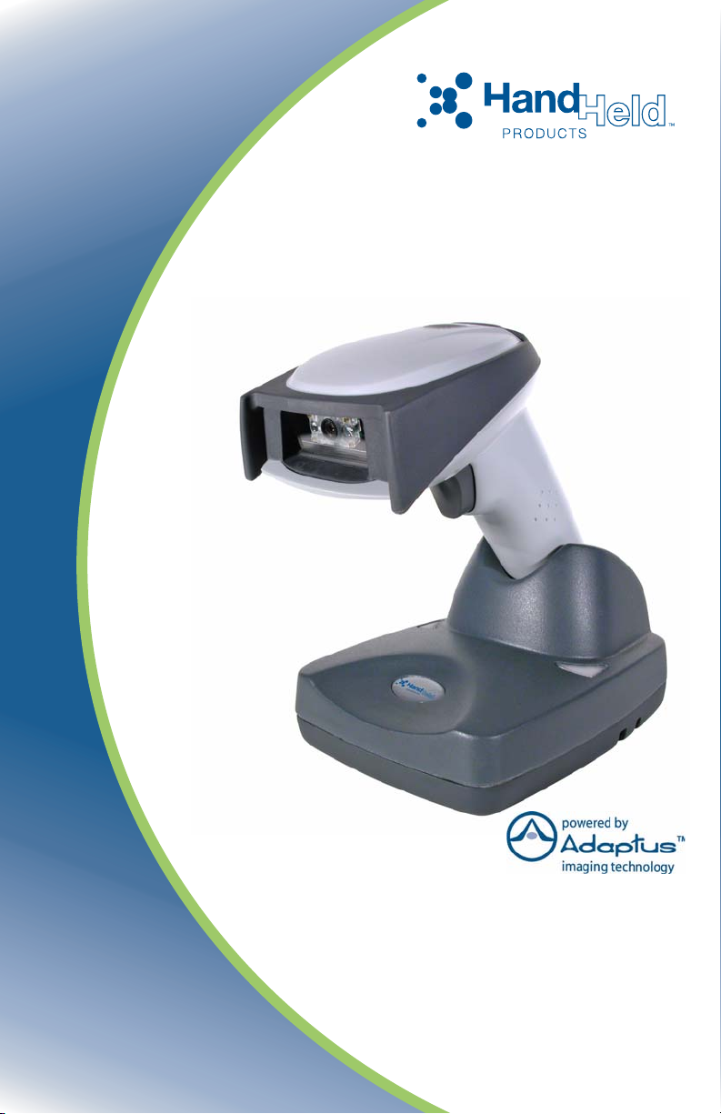
Required Safety Labels
IT5620
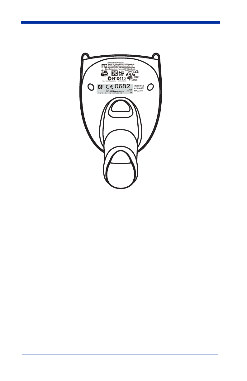
Page 8
IT2020
g
g
F
<526
MO
Q,
VW
C
DL
F
E
<1
X
HD
G
V
RU3GOH
N
OO
A
D)
H
WWW
V
+
H
OHWDHQDN
G
Q
D
+
6
D
(
Q
L
(
K&
'
6(&&$
QL
7,
HGD0
JQLGQH3VWQHWD3Q
%
%
;0'
;
0
%
J
LH
&
U
,
+
',
R
DGD
)
GQD68
&
QD&
&)
Page 9

Table of Contents
Chapter 1 - Getting Started
About This Manual ............................................................... 1-1
Unpacking the System .......................................................... 1-2
Models .................................................................................. 1-2
Cordless System: Main Components.................................... 1-3
About the Battery.................................................................. 1-3
Proper Disposal of the Battery ....................................... 1-4
Base Charge Mode................................................................ 1-5
Linking Scanner to Base....................................................... 1-6
Scanner Modes...................................................................... 1-6
Unlinking the Scanner.................................................... 1-6
Single Scanner Operation ..................................................... 1-7
Locked Link Mode - Single Scanner ............................. 1-7
Open Link Mode - Single Scanner................................. 1-7
Override Locked Scanner............................................... 1-7
Multiple Scanner Operation.................................................. 1-8
Scanner Name....................................................................... 1-8
Changing Scanner Name - Serially ................................ 1-8
Changing Scanner Name - via Bar Codes...................... 1-9
Scanner Report.................................................................... 1-10
Application Work Groups................................................... 1-10
Application Work Group Selection.............................. 1-11
Resetting the Standard Product Default Settings:
Current Application Work Group .................................... 1-12
Resetting the Standard Product Default Settings: All
Application Work Groups................................................ 1-12
Using the Scanner with Bluetooth Devices ........................ 1-13
Changing Bluetooth PIN Code..................................... 1-13
Out-of-Range Alarm........................................................... 1-13
Duration........................................................................ 1-13
Alarm Sound Type ....................................................... 1-14
Data Accumulation Mode................................................... 1-14
Beeper and LED Sequences and Their Meaning................ 1-14
IT5620 LED Sequences and Their Meaning................ 1-15
IT2020 LED Sequences and Their Meaning................ 1-15
i
Page 10

Basic Operation of the Cordless System.............................1-16
System Conditions........................................................1-17
Communication Between the Cordless System
and the Host .................................................................. 1-18
Connecting the Base When Powered by Host
(Keyboard Wedge) ...........................................................1-18
Reading Techniques ............................................................ 1-20
Resetting the Standard Product Defaults............................. 1-20
Plug and Play....................................................................... 1-20
Keyboard Wedge Connection .............................................1-21
Laptop Direct Connect.................................................. 1-21
RS-232 .......................................................................... 1-21
Wand Emulation Plug & Play ......................................1-22
IBM 4683 Ports 5B, 9B, and 17 Interface........................... 1-23
Connecting the Base with USB........................................... 1-24
IBM SurePos ................................................................ 1-25
USB PC or Macintosh Keyboard.................................. 1-25
USB HID ......................................................................1-26
USB Com Port Emulation ............................................1-26
Connecting the Base with Serial Wedge.............................1-27
Chapter 2 - Terminal Interfaces
Terminal ID...........................................................................2-1
Supported Terminals ............................................................. 2-2
Keyboard Country.................................................................2-4
Keyboard Style...................................................................... 2-5
Keyboard Modifiers .............................................................. 2-6
Connecting the Base with RS-232 Serial Port ......................2-7
RS-232 Baud Rate .......................................................... 2-8
RS-232 Word Length: Data Bits, Stop Bits, and Parity .2-9
RS-232 Handshaking....................................................2-10
Host ACK Selection .....................................................2-10
Host ACK Enable ......................................................... 2-11
ii
Page 11

Wand Emulation..................................................................2-13
Wand Emulation Connection........................................2-13
Wand Emulation Transmission Rate ............................2-14
Wand Emulation Polarity..............................................2-14
Wand Emulation Idle ....................................................2-15
Wand Emulation Data Block Size ................................2-15
Wand Emulation Delay Between Blocks......................2-15
Wand Emulation Overall Checksum ............................2-16
Chapter 3 - Output
Good Read Indicators............................................................3-1
Beeper – Good Read .......................................................3-1
Beeper Volume – Good Read .........................................3-1
Beeper Pitch – Good Read..............................................3-2
Beeper Duration – Good Read........................................3-2
LED – Good Read...........................................................3-2
Number of Beeps – Good Read ......................................3-3
Good Read Delay ..................................................................3-3
User-Specified Good Read Delay...................................3-3
Scanner Trigger Modes .........................................................3-4
Manual/Serial Trigger, Low Power ................................3-4
Automatic Trigger...........................................................3-5
Presentation Mode ..........................................................3-5
Hands Free Time-Out............................................................3-6
Reread Delay .........................................................................3-6
User-Specified Reread Delay..........................................3-6
Centering Window ................................................................3-7
Output Sequence Overview...................................................3-8
Output Sequence Editor ..................................................3-9
Require Output Sequence ...............................................3-9
Multiple Symbols ................................................................3-12
No Read...............................................................................3-12
Video Reverse .....................................................................3-12
iii
Page 12

Chapter 4 - Data Editing
Prefix/Suffix Overview ......................................................... 4-1
To Add a Prefix or Suffix: .............................................4-2
To Clear One or All Prefixes or Suffixes: ...................... 4-3
To Add a Carriage Return Suffix to all Symbologies ....4-3
Prefix Selections ............................................................. 4-3
Suffix Selections............................................................. 4-4
Function Code Transmit ................................................. 4-4
Intercharacter, Interfunction, and Intermessage Delays........ 4-4
Intercharacter Delay .......................................................4-5
User Specified Intercharacter Delay...............................4-5
Interfunction Delay.........................................................4-6
Intermessage Delay......................................................... 4-6
Chapter 5 - Data Formatting
Data Format Editor Introduction...........................................5-1
To Add a Data Format .................................................... 5-1
Other Programming Selections....................................... 5-2
Data Format Editor Commands......................................5-2
Data Format Editor ......................................................... 5-4
Data Formatter................................................................5-5
Alternate Data Formats................................................... 5-5
Chapter 6 - Symbologies
Introduction ........................................................................... 6-1
All Symbologies.................................................................... 6-1
Message Length ....................................................................6-2
Codabar ................................................................................. 6-3
Codabar Start/Stop Characters ....................................... 6-3
Codabar Check Character...............................................6-3
Codabar Concatenation................................................... 6-4
Codabar Message Length ...............................................6-5
iv
Page 13

Code 39..................................................................................6-5
Code 39 Start/Stop Characters .......................................6-5
Code 39 Check Character ...............................................6-6
Code 39 Message Length................................................6-6
Code 39 Append .............................................................6-7
Code 32 Pharmaceutical (PARAF).................................6-7
Full ASCII.......................................................................6-8
Code 39 Code Page.........................................................6-9
Interleaved 2 of 5...................................................................6-9
Check Digit .....................................................................6-9
Interleaved 2 of 5 Message Length...............................6-10
Code 93................................................................................6-11
Code 93 Message Length..............................................6-11
Code 93 Code Page.......................................................6-11
Code 2 of 5 ..........................................................................6-12
Code 2 of 5 Message Length ........................................6-12
IATA Code 2 of 5 Message Length..............................6-13
Matrix 2 of 5........................................................................6-13
Matrix 2 of 5 Message Length......................................6-14
Code 11................................................................................6-14
Check Digits Required..................................................6-14
Code 11 Message Length..............................................6-15
Code 128..............................................................................6-15
ISBT 128 Concatenation...............................................6-16
Code 128 Message Length............................................6-16
Code 128 Code Page.....................................................6-16
Code 128 Function Code Transmit...............................6-17
Telepen ................................................................................6-17
Telepen Output .............................................................6-17
Telepen Message Length ..............................................6-18
UPC A .................................................................................6-18
UPC A Check Digit ......................................................6-18
UPC A Number System................................................6-19
UPC A Addenda ...........................................................6-19
UPC A Addenda Required............................................6-19
UPC A Addenda Separator ...........................................6-20
UPC-A/EAN-13 with Extended Coupon Code ...................6-20
v
Page 14

UPC E0 and UPC E1........................................................... 6-21
UPC E0 and UPC E1 Expand....................................... 6-21
UPC E0 and UPC E1 Addenda Required.....................6-21
UPC E0 and UPC E1 Addenda Separator .................... 6-22
UPC E0 Check Digit..................................................... 6-22
UPC E0 Number System .............................................. 6-22
UPC E0 Addenda.......................................................... 6-23
EAN/JAN 13 ....................................................................... 6-23
EAN/JAN 13 Check Digit ............................................ 6-23
EAN/JAN 13 Addenda ................................................. 6-24
EAN/JAN 13 Addenda Required .................................6-24
EAN/JAN 13 Addenda Separator.................................6-24
ISBN Translate ............................................................. 6-25
EAN/JAN 8 ......................................................................... 6-25
EAN/JAN 8 Check Digit .............................................. 6-25
EAN/JAN 8 Addenda ................................................... 6-26
EAN/JAN 8 Addenda Required ...................................6-26
EAN/JAN 8 Addenda Separator...................................6-26
MSI...................................................................................... 6-27
MSI Check Character ...................................................6-27
MSI Message Length.................................................... 6-28
Plessey Code .......................................................................6-28
Plessey Message Length...............................................6-28
RSS Limited ........................................................................ 6-29
RSS Expanded..................................................................... 6-30
RSS Expanded Message Length................................... 6-30
EAN•UCC Emulation ......................................................... 6-30
China Post Code..................................................................6-31
Korea Post Code.................................................................. 6-32
Korea Post Message Length ......................................... 6-32
PosiCode A and B ............................................................... 6-33
PosiCode Message Length............................................ 6-33
Codablock F ........................................................................ 6-34
Codablock F Message Length ......................................6-34
Code 16K ............................................................................6-35
Code 16K Message Length........................................... 6-35
vi
Page 15

Code 49................................................................................6-36
Code 49 Message Length..............................................6-36
Chapter 7 - Interface Keys
Keyboard Function Relationships .........................................7-1
Supported Interface Keys ......................................................7-3
Chapter 8 - Utilities
To Add a Test Code I.D. Prefix to All Symbologies ............8-1
Reset Scanner ........................................................................8-1
Show Software Revision .......................................................8-1
Show Data Format.................................................................8-1
Scanner Report ......................................................................8-2
Scanner Address ....................................................................8-2
Base Address .........................................................................8-2
Resetting the Standard Product Default Settings:
Current Application Work Group .......................................8-2
Resetting the Standard Product Default Settings: All
Application Work Groups...................................................8-3
Temporary Visual Menu 2003 Configuration .......................8-3
Chapter 9 - Visual Menu 2003
Visual Menu 2003 Introduction ............................................9-1
Installing Visual Menu 2003 from the Web ...................9-1
Chapter 10 - Serial Programming Commands
Conventions.........................................................................10-1
Menu Command Syntax......................................................10-1
Query Commands .........................................................10-2
Concatenation of Multiple Commands .........................10-3
Responses......................................................................10-3
Examples of Query Commands ....................................10-3
Trigger Commands..............................................................10-4
Resetting the Standard Product Default Settings:
Current Application Work Group .....................................10-5
vii
Page 16

Resetting the Standard Product Default Settings: All
Application Work Groups ................................................10-5
Menu Commands ................................................................ 10-6
Chapter 11 - Product Specifications
IMAGETEAM 5620 Product Specifications ...................... 11-1
IMAGETEAM 2020 Product Specifications ...................... 11-2
IMAGETEAM 5620 Depth of Field ................................... 11-3
Chapter 12 - Maintenance
Maintenance ........................................................................ 12-1
Cleaning the Scanner’s Window ..................................12-1
Inspecting Cords and Connectors ................................. 12-1
Replacing the IT2020 Interface Cable:......................... 12-2
Troubleshooting Base.......................................................... 12-2
Chapter 13 - Customer Support
Product Service and Repair.................................................13-1
Online Product Service and Repair Assistance ............13-2
Technical Assistance...........................................................13-2
Online Technical Assistance ........................................13-2
Limited Warranty ................................................................ 13-2
Appendix A
Symbology Chart ................................................................. A-1
ASCII Conversion Chart (Code Page 1252) ........................ A-2
Code Page Mapping of Printed Bar Codes .......................... A-4
viii
Page 17

1
Getting Started
The IMAGETEAM 5620 cordless scanning system consists of one IT2020-5A
base and one IT5620 Cordless Linear Imager. Up to seven scanners may be
linked to one base. The IT5620 marks a new performance level for hand held
scanners. The IT5620 is powered by Hand Held Products Adaptus
Technology. The performance of Adaptus technology delivers aggressive read
rates and depths of field on 1D codes.
Designed for today’s demanding retail and commercial environments, the
IT5620 offers a superior reading range, durability, and the ability to read poor
quality bar codes. Linear imaging technology is defined by a bright and sharply
focused aiming line, high resolution imaging, and fast reading speed. The
IT5620 is comfortable to hold, easy to use, rugged, and excellent for retail
applications, as well as for all general scanning applications.
The cordless system is an economical, durable solution for a wide variety of
portable data collection applications. The cordless system features:
• a tough, ergonomic thermoplastic housing for comfort and durability.
• an advanced two-way spread-spectrum radio, Bluetooth
technology
• a wide range of interfaces: keyboard wedge, wand emulation, RS-232
terminals, USB, and legacy decoders.
• visible and audible feedback for confirmation of a successful decode.
• a rechargeable battery designed to operate through a whole work day.
The cordless system can be programmed for many communication parameters
and input/output protocols compatible to the host, as well as advanced data
editing and formatting.
®
wireless
TM
Imaging
About This Manual
This manual contains information to help you set up, operate, and program the
cordless system. Product specifications, connector pinouts, a troubleshooting
guide, and customer support information are also provided.
Hand Held Products bar code scanners are factory programmed for the most
common terminal and communications settings. If you need to change these
settings, programming is accomplished by scanning the bar codes in this guide.
An asterisk (*) next to an option indicates the default setting.
This section contains the following information:
• Unpacking the System
• Cordless System Main Components
• Battery and Charging Information
• Linking the Scanner to the Base
• Beeper and LED Sequences and Their Meaning
• Basic Operation of the Cordless System
• Communication Between the Cordless System and the Host
IMAGETEAM™ 2020/5620 System Manual 1 - 1
Page 18

• Connection of the Base to an Interface
Unpacking the System
After you open the shipping carton containing the product, take the following
steps:
• Check to make sure everything you ordered is present.
• Save the shipping container for later storage or shipping.
• Check for damage during shipment. Report damage immediately to the
carrier who delivered the carton.
Models
Models Description
2020-5A Base: Keyboard wedge, TTL level 232, TTL level 232
serial wedge, IBM 4683, wand emulation, USB keyboard,
USB HID, USB retail (IBM SurePOS)
2020-CB Base with charger only (no host interfaces)
5620SR0C0 Cordless Linear Scanner
1 - 2 IMAGETEAM™ 2020/5620 System Manual
Page 19
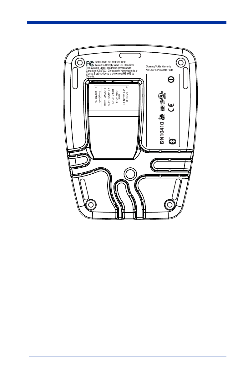
Cordless System: Main Components
Battery Contained in Handle
About the Battery
Use only the Li-ion battery packs provided by Hand Held Products. The
use of any battery pack not sold by Hand Held Products will void your
!
warranty and may result in damage to your unit.
Power is supplied to the cordless scanner by a rechargeable battery that is
integrated in the scanner handle. Each scanner is shipped with a battery.
Product Specifications
beginning on page 11-1
.)
(See
Charging Information
The battery is designed to charge while the scanner is positioned in the cordless
base unit. Refer to "IT2020 LED Sequences and Their Meaning" on page 1-15
for an interpretation of the Charge Status indicators.
• Place the scanner in the base that is connected to an appropriate power
supply.
IMAGETEAM™ 2020/5620 System Manual 1 - 3
Page 20

Battery Recommendations
• Batteries are shipped approximately 30% to 60% charged and should be fully
charged for maximum charge capacity.
• The battery is a lithium ion cell and can be used without a full charge, as well
as can be charged without fully discharging, without impacting the battery life.
There is no need to perform any charge/discharge conditioning on this cell
type battery.
• Do not disassemble the battery. There are no user-serviceable parts in the
battery.
• Keep the base connected to power when the host is not in use.
• Replace a defective battery immediately since it could damage the IT5620.
• Don’t short-circuit a battery or throw it into a fire. It can explode and cause
severe personal injury.
• Although your battery can be recharged many times, it will eventually be
depleted. Replace it after the battery is unable to hold an adequate charge.
• If you are not sure if the battery or charger is working properly, send it to Hand
Held Products or an authorized Hand Held Products service center for
inspection.
Proper Disposal of the Battery
When the battery has reached the end of its useful life, the
battery should be disposed of by a qualified recycler or
hazardous materials handler. Do not incinerate the battery or
dispose of the battery with general waste materials. You may
send batteries to Hand Held Products (postage paid). The
shipper is responsible for complying with all federal, state, and
local laws and regulations related to the packing, labeling,
Product Service Department (see 13-1) for recycling or disposal information.
Since you may find that your cost of returning the batteries significant, it may be
more cost effective to locate a local recycle/disposal company.
manifesting, and shipping of spent batteries. Contact the
1 - 4 IMAGETEAM™ 2020/5620 System Manual
Page 21
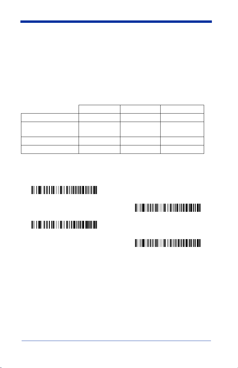
Base Charge Mode
In order for the battery to be charged, there must be enough voltage for the
circuitry to work. There are three conditions during which power can be supplied
to the base:
Condition 1: 9VDC power supply connected to the barrel connector
Condition 2: 12VDC host power source only
Condition 3: 5VDC host power source only
The chart below describes each selection by condition.
Condition 1 Condition 2 Condition 3
Automatic Fast Charge Slow Charge No Charge
Full Charge Rate Fast Charge Fast Charge No Charge
Low Charge Rate Slow Charge Slow Charge No Charge
Battery Charge Off No Charge No Charge No Charge
Using a slow charge rate draws less current (power) from the input power source
when the battery is mostly discharged.
Scan the appropriate bar code for your application.
* Automatic
Default = Automatic
.
Full Charge Rate
Low Charge Rate
Battery Charge Off
IMAGETEAM™ 2020/5620 System Manual 1 - 5
Page 22
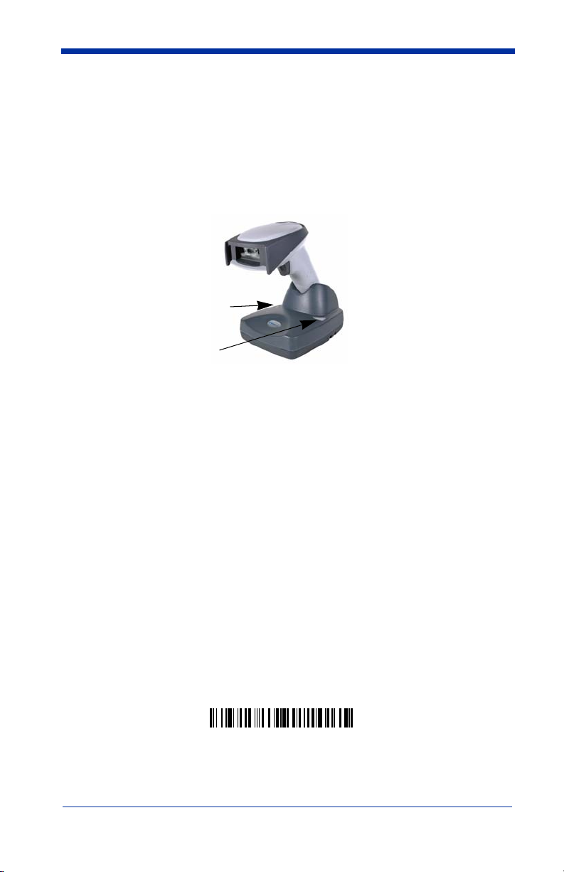
Linking Scanner to Base
When newly shipped or defaulted to factory settings, the base and scanner are
not linked. Once the scanner is placed into the base, the software automatically
links the scanner and the base. If the scanner and base have previously been
linked, you do not receive any feedback. If this is the first time that the scanner
and base are linked, both devices emit a short chirp when their radios link. At
this point, you are set to one imager to one base.
IT5620 Scanner
Green LED
Red LED
1. Provide power to the base.
2. Place the IT5620 into the base. The scanner and base link.
3. To determine if your cordless system is set up correctly, scan one of the
sample bar codes in the back of this manual. If the scanner provides a
single good read beep and the green LED lights, the scanner has
successfully linked to the base. If you receive a triple error beep and the red
LED lights, the scanner has not linked to the base.
IT2020-5A Cordless
Scanner Modes
The IT5620 is capable of working in single scanner mode, multiple scanner
mode, or with Blutetooth devices, other than the IT2020-5A base.
Unlinking the Scanner
If the base has an scanner linked to it, that scanner must be unlinked before a
new scanner can be linked. Once the previous scanner is unlinked, it will no
longer communicate with the base. To unlink an scanner from the base, scan
the Unlink Scanner bar code below.
Unlink Scanner
1 - 6 IMAGETEAM™ 2020/5620 System Manual
Page 23

Single Scanner Operation
There are two link modes to accommodate different applications: Locked Link
Mode and Open Link Mode. Scan the appropriate bar codes included in the
Open Link and Locked Link Mode explanations that follow to switch from one
mode to another.
Locked Link Mode - Single Scanner
If you link an scanner to a base using the Locked Link Mode, other scanners are
blocked from being linked if they are inadvertently placed into the base. If you
do place a different scanner into the base, it will charge the scanner, but the
scanner will not be linked.
To use a different scanner, you need to unlink the original scanner by scanning
the Unlink Scanner bar code. (See "Scanner Modes" on page 1-6.)
Open Link Mode - Single Scanner
When newly shipped or defaulted to factory settings, the base and scanner are
not linked. By placing an scanner into the base, they establish a link. Placing a
different scanner into the base establishes a new link and the old scanner is
unlinked. Each time an scanner is placed into the base, it becomes the linked
scanner; the old scanner is unlinked.
Default = Locked Link Mode
* Locked Link Mode
(Single Scanner)
.
Open Link Mode
(Single Scanner)
Override Locked Scanner
If you need to replace a broken or lost scanner that is linked to a base, scan the
Override Locked Scanner bar code below with a new scanner and place that
scanner in the base. The locked link will be overridden; the broken or lost
scanner’s link with the base will be removed, and the new scanner will be linked.
Override Locked Scanner
(Single Scanner)
IMAGETEAM™ 2020/5620 System Manual 1 - 7
Page 24

Multiple Scanner Operation
To put the scanner in multiple scanner mode, scan the bar code below. Once
you scan this bar code, the scanner is unlinked from the base and must be
placed into the base to re-link.
Multiple Scanner Operation
Note: Multiple Scanner Operation Mode allows you to link up to 7 scanners to
one base. You cannot join an eighth scanner until you unlink one of the
7 scanners or take an scanner out of range.
Scanner Name
You are able to assign a name to each scanner you are using. It will be helpful
to name the scanners if you have multiple scanners linked to one base so that
you will be able to control the scanner receiving imaging commands sent from
the base. The default name for an IT5620 is “IT5620”. If you have more than
one IT5620 linked to a base, the first scanner that is linked to the base receives
commands addressed using this name.
Changing Scanner Name - Serially
If you wish to change the name, you may change it via a serial command (refer
to "Menu Command Syntax" on page 10-1) or via a bar code command. To
change the name serially, unlink all except one of the IT5620s from the base.
Send “:IT5620:BT_NAM
wish to change the name of additional IT5620s, re-link them one at a time and
repeat the “:IT5620:BT_NAM
name
.”, where
name.”
name
is the new scanner name. If you
command for each scanner.
1 - 8 IMAGETEAM™ 2020/5620 System Manual
Page 25

Changing Scanner Name - via Bar Codes
If you wanted set up your scanners with names 0001-0007, you may scan the
bar codes below.
the scanner to re-link to the base before scanning the next bar code to name the
next scanner.
Scan the Reset bar code after each name change and wait for
0001
0002
0002
0003
0004
0005
0006
0007
Reset
Alternatively, you may change the name with a bar code command if you cannot
send serial commands to the base. One way to do this is to scan the bar code
below and scan a number for the scanner name. For example, if you had 7
scanners to one base, scan the bar code below with the first scanner, scan the
1 bar code on the Programming Chart inside the back cover of this manual and
scan Save. Then scan the Reset bar code and wait for the scanner to re-link to
the base before scanning the next bar code. Repeat that process for scanner
number 2 , 3, 4 etc.
Scanner Name
If you want to assign an alphabetic name to the scanner, create a Code 128 bar
code containing “~BT_NAM
83), where
or on the Programming Chart inside the back cover of this manual). You may
use Barcode Builder, which is included with Quick*View. You may download
Quick*View from the Hand Held Products website: www.handheld.com
name
is the new scanner name. Scan the Reset bar code (page 1-9
name
.” followed by a FNC3 character (hexidecimal
.
IMAGETEAM™ 2020/5620 System Manual 1 - 9
Page 26

Scanner Report
Scan the bar code below to generate a report for the connected scanners. The
report indicates the port, work group, scanner name, and address.
Scanner Report
Application Work Groups
Your cordless system can have up to seven scanners linked to one base. You
can also have up to seven work groups. If you want to have all of the scanners’
settings programmed alike, you don’t need to use more than one work group. If
you want each scanner to have unique settings (e.g., beeper volume, prefix/
suffix, data formatter), then you may program each scanner to its own unique
work group and may program each scanner independently. Visual Menu 2003
(page 9-1) makes it easy for you to program your system for use with multiple
scanners and multiple work groups.
The scanner keeps a copy of the menu settings it is using. Whenever the
scanner is connected or reconnected to a base, the scanner is updated with the
latest settings from the base for its work group. The scanner also receives menu
setting changes processed by the base. If an scanner is removed from one base
and placed into another base, it will be updated with the new base settings for
whatever work group that the scanner was previously assigned. For example, if
the scanner was in work group 1 linked to the first base, it will be placed in work
group 1 in the second base with the associated settings.
1 - 10 IMAGETEAM™ 2020/5620 System Manual
Page 27

Application Work Group Selection
This programming selection allows you to assign an scanner to a work group by
scanning the bar code below. You may then program the settings (e.g., beeper
volume, prefix/suffix, data formatter) that your application requires.
* Group 0
Group 1
Group 2
Group 3
Group 4
Group 5
Group 6
IMAGETEAM™ 2020/5620 System Manual 1 - 11
Page 28

Resetting the Standard Product Default Settings: Current Application Work Group
If you aren’t sure what programming options are in your scanner, or you’ve
changed some options and want the standard product default settings restored,
scan the
code below.
The Menu Commands starting on page 10-6 list the factory default settings for
each of the commands (indicated by an asterisk (*) on the programming pages).
Note: Scanning this bar code also causes both the scanner and the base to
Note: If your scanner is in multiple scanner mode and you scan either the
Standard Product Default Settings: Current Application Group
perform a reset and become unlinked. Refer to "Linking Scanner to
Base" on page 1-6 for additional information.
Standard Product Default Settings:
Current Application Group
current or all application group default bar code, you will hear up to 30
seconds of beeping while all scanners are re-linked from the base and the
settings are defaulted to * settings. The default interface is keyboard
wedge and the default scanner mode is single scanner locked link mode.
bar
Resetting the Standard Product Default Settings: All Application Work Groups
The following bar code defaults all of the work groups to the factory settings.
Standard Product Default Settings:
All Application Groups
The Menu Commands starting on page 10-6 list the standard product default
settings for each of the commands (indicated by an asterisk (*) on the
programming pages).
1 - 12 IMAGETEAM™ 2020/5620 System Manual
Page 29

Using the Scanner with Bluetooth Devices
The IT5620 scanner may be used either with the IT2020-5A base or with other
Bluetooth devices. Scanning the Non-Base Bluetooth Connection bar code
below allows the scanner to be used with other Bluetooth devices (e.g., PDA, PC
- Bluetooth USB Adapter). After you scan the bar code below, follow the
instructions supplied with your Bluetooth device to locate the scanner and
connect to it. If you go out of range with your scanner, the scanner automatically
reconnects to the Bluetooth device. If you want to relink to the IT2020-5A base,
refer to
Operation"
Changing Bluetooth PIN Code
Some devices require a PIN code as part of the Bluetooth security features. Your
scanner’s default PIN is 1234, which you may need to enter the first time you
connect to your PDA or PC. The PIN code must be numeric and between 1 and
16 characters. To change the PIN, scan the bar code below and then scan the
appropriate numeric bar codes from the Programming Chart inside the back
cover of this manual. Scan Save to save your selection.
"Single Scanner Operation"
on page 1-8
.
Non-Base BT Connection
Bluetooth PIN
on page 1-7 or
"Multiple Scanner
Out-of-Range Alarm
Duration
If your scanner is out range of the base, an alarm sounds from both your base
and scanner. To activate the alarm options for the scanner or the base and to
set the alarm duration, scan the appropriate bar code below and then set the
time-out duration (from 0-3000 seconds) by scanning digits on the Programming
Chart inside the back cover, then scanning Save.
Base Alarm Duration
IMAGETEAM™ 2020/5620 System Manual 1 - 13
Default = 0 sec (no alarm).
Scanner Alarm Duration
Page 30

Note: If you are out of range when you scan a bar code, you will receive an error
beep even if you do not have the alarm set. You receive the error beep
since the data could not be communicated to the base or the host.
Alarm Sound Type
If you have set the out-of-range alarm enabled, you may change the alarm type
for the scanner or base by scanning the appropriate bar code below and then
scanning a digit (0-7) bar code and the Save bar code on the Programming Chart
inside the back cover of this manual.
application.
Base Alarm Type
Default = 0.
Set the sound type to fit your
Scanner Alarm Type
Data Accumulation Mode
Scan the bar codes below to turn data accumulation (batch) mode on and off. If
data accumulation mode is on, bar code data is stored when the scanner is out
of range of the base and transmitted once the scanner is back in range.
Data Accumulation Mode On
* Data Accumulation Mode Off
Beeper and LED Sequences and Their Meaning
The IT5620 contains LEDs on the top of the unit to indicate its power up,
communication, and battery status. Simply stated, red LED = error; green
LED = success of any type. The unit’s audible indicators have meaning as well:
3 beeps = error; 2 beeps = menu change; 1 beep = all other successes.
The table below lists the indication and cause of the LED illumination and beeps
for the IT5620.
1 - 14 IMAGETEAM™ 2020/5620 System Manual
Page 31

IT5620 LED Sequences and Their Meaning
LED Indication Beeper Indication Cause
Normal Operation
Red Flash None Battery low
Green Flash 1 beep
Red, blinking 3 beeps Failed communication
Menu Operation
Green Flash 2 beeps Successful menu change
Red, blinking 3 beeps Unsuccessful menu change
Successful communication
or linking
IT2020 LED Sequences and Their Meaning
The base contains a red LED that indicates the status of the unit and verifies its
communication with the host system and a green LED that indicates scanner
battery charge condition.
The tables below list the indication and cause of the LED illumination and beeps
for the IT2020.
System Condition System Status Indicator (Red LED)
Power On/System Idle LED is on
Power On/Diagnostic Error Blink LED for long duration, pulsing indefinitely
Receiving Data (IT2020-5A only)
Base requests status from its
own Bluetooth radio
Blink LED for short duration in multiple pulses. Occurs
while transferring data to/from the RF module or the Host
port.
Blink LED once (occurs approx. every 30 seconds)
IMAGETEAM™ 2020/5620 System Manual 1 - 15
Page 32

Note: Charging only occurs with external power applied to the IT2020 or 12 volt
Host power.
Charge Condition Charge Status Indicator (Green LED)
Scanner inserted into base Three flashes
>80% charged On continuously
30% to 80% charged Slow flash, 1 second on, 1 second off
<30% charged Fast flash, 300 mSec on, 300 mSec off
Basic Operation of the Cordless System
Cordless Base
The cordless base provides the link between the cordless scanner and the host
system. The base contains an interface assembly and an RF communication
module. The RF communication module performs the data exchange between
the cordless scanner and the interface assembly. The control assembly
coordinates the central interface activities including: transmitting/receiving
commands and data to/from the host system, performing software activities
(parameter menuing, visual indicator support, power-on diagnostics), and data
translation required for the host system.
The base also is the scanner battery charger with the external 9VDC power
source applied. Once you place the scanner into base, the base green LED
responds according to the Charge Status Indicator table above.
The base can be powered by the Host (parasitic power mode). If the base is in
parasitic power mode without the 9VDC power source, the base will still function,
but will not charge the battery.
RF (Radio Frequency) Module Operation
The cordless system uses a state-of-the-art two-way Bluetooth radio to transmit
and receive data between the scanner and the base. Designed for point-to-point
and multipoint-to-single point applications, the radio operates using a license
free ISM band, which sends relatively small data packets at a fast data rate over
a radio signal with randomly changing frequencies, makes the cordless system
highly responsive to a wide variety of data collection applications and resistant to
noisy RF environments. Bluetooth Class 2 power level provides range of 33 feet
(10m) depending on the environment.
1 - 16 IMAGETEAM™ 2020/5620 System Manual
Page 33

Cordless Scanner
The cordless scanner enables fast and accurate bar code scanning using a noncontact linear scanner.
The scanner is comprised of a linear scanner, a decode/control assembly, and
an RF communication module. The scan engine performs the bar code image
illumination and sensing. The decode/control assembly coordinates the central
communication activities including: capturing and decoding the bar code image
data, performing software activities (parameter menuing, visual indicator
support, low battery indication), and data translation required for the host system.
The RF communication module performs the data exchange between the
scanner and the base.
System Conditions
The components of the cordless system interact in specific ways as you
associate a scanner to a base, as you move a scanner out of range, bring a
scanner back in range, or swap scanners between two cordless systems. The
following information explains the cordless system operating conditions.
Linking Process
Once an imager is placed into the base, the imager’s battery charge status is
checked, and software automatically detects the imager and links it to the base
depending on the selected link mode.
Scanner Is Out of Range
The cordless scanner is in communication with its base, even when it is not
transmitting bar code data. Whenever the scanner can’t communicate with the
base for a few seconds, it is out of range. If the scanner is out of range and you
scan a bar code, the scanner issues a triple beep indicating no communication
with the base. In addition, your scanner and base can sound an alarm if
programmed to emit an alarm. See Out-of-Range Alarm on page 1-13.
Scanner Is Moved Back Into Range
The scanner re-links if the scanner or the base have been reset or out of range.
If the scanner re-links, you will hear a single chirp when the re-linking process
(uploading of the parameter table) is complete.
Out of Range and Back into Range with Data Accumulation Mode
On
The scanner may store a number of symbols (approximately 500 UPC symbols,
others may vary) when out of range and then send them to the base when back
in range. You will not hear a communication error beep in this mode, but you will
hear a short buzz when you pull the trigger if the radio communication is not
working. Once the radio connection is made, the scanner produces a series of
beeps while the data is being transferred to the base.
IMAGETEAM™ 2020/5620 System Manual 1 - 17
Page 34

Communication Between the Cordless System and the Host
The cordless scanner provides immediate feedback in the form of a “good read”
indication (a green LED on the scanner and an audible beep) after a bar code is
scanned correctly and the base has acknowledged receiving the data. This is
possible since the cordless system provides two-way communication between
the scanner and the base.
When data is scanned, the data is sent to the host system via the base unit.
Confirmation from the host system or the base indicates that the data sent was
received by the host. The cordless scanner recognizes data acknowledgement
(ACK) from the base unit. If it cannot be determined that the data has been
properly sent to the base, the scanner issues an error indication. You must then
check to see if the scanned data was received by the host system.
3) Base sends
d
a
e
R
d
o
o
G
)
1
e
s
a
b
m
o
f
r
K
C
A
)
2
data to host
Connecting the Base When Powered by Host (Keyboard Wedge)
A base can be connected between the keyboard and PC as a “keyboard wedge,”
plugged into the serial port, or connected to a portable data terminal in wand
emulation or non decoded output mode. The following is an example of a
keyboard wedge connection:
1. Turn off power to the terminal/computer.
1 - 18 IMAGETEAM™ 2020/5620 System Manual
Page 35
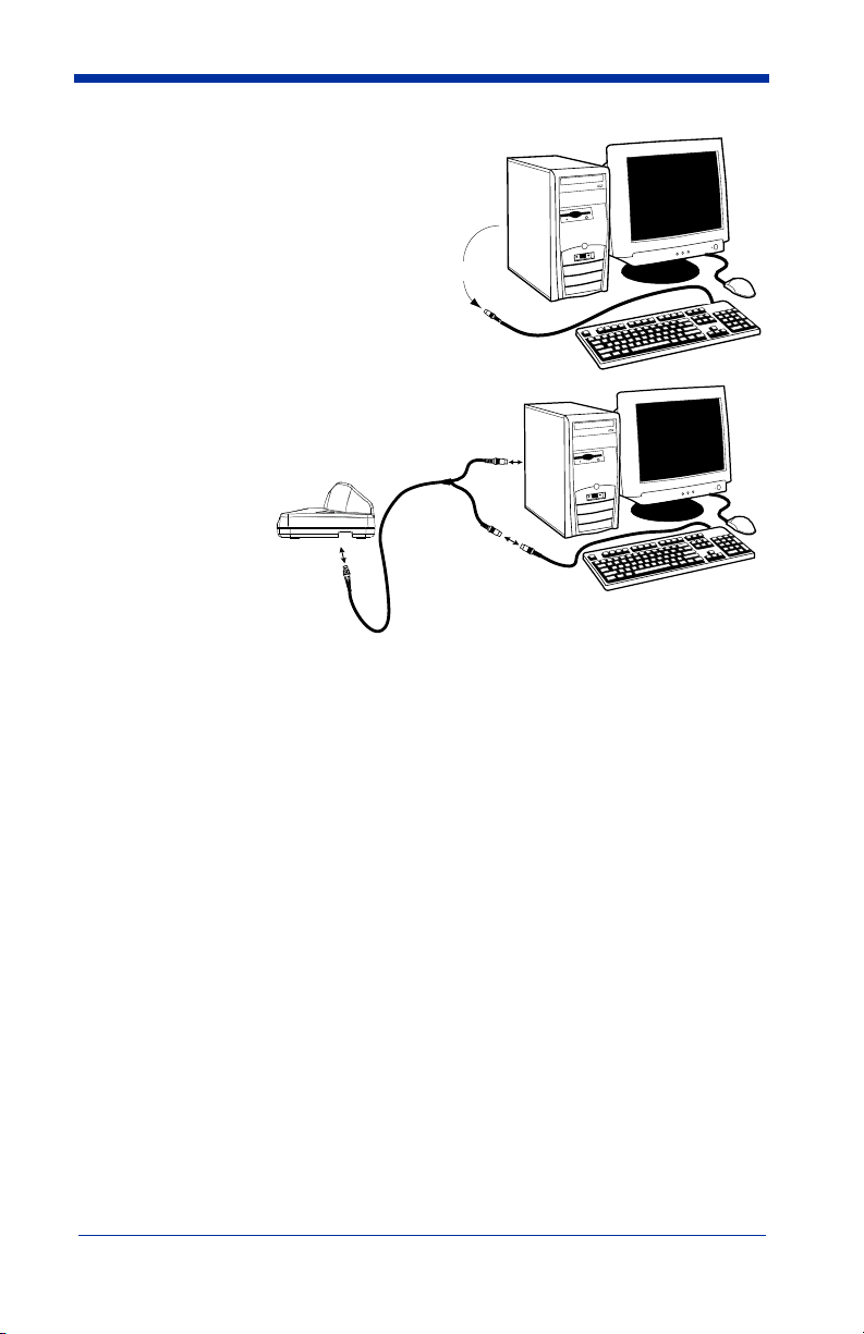
2. Disconnect the keyboard cable from the back of the terminal/ computer.
Disconnect
3. Connect the
appropriate
interface cable
to the base and
to the terminal/
3
computer and
keyboard.
4. Turn the
terminal/
computer power
1
2
back on.
5. Program the
base for the
keyboard wedge interface. See "Keyboard Wedge Connection" on page 1-
21.)
6. Verify the base operation by scanning a bar code from the Sample Symbols in the back of this manual.
Note: Without using the 9-volt external, power supply, the base only uses
enough power from the host to operate the interface. The scanner’s
battery is not charged when in this mode. Using the 9-volt, external power
supply allows the scanner’s battery to be charged, and no power is drawn
from the host.
IMAGETEAM™ 2020/5620 System Manual 1 - 19
Page 36

Reading Techniques
The scanner has a view finder that projects a bright red aiming beam that
corresponds to its horizontal field of view. The aiming line should be centered
horizontally over the bar code; it will not read if the aiming line is in any other
direction.
Good Read
Bad Read
The best focus point for reading most code densities is about 5 inches (12.7 cm)
from the unit. To read single or multiple symbols (on a page or on an object),
hold the scanner at an appropriate distance from the target, pull the trigger, and
center the aiming line on the symbol.
Bad Read
Resetting the Standard Product Defaults
If you aren’t sure what programming options are in your scanner, or you’ve
changed some options and want the factory settings restored, scan the
Standard Product Default Settings
The Menu Commands starting on page 10-6 lists the factory default settings for
each of the commands (indicated by an asterisk (*) on the programming pages).
Note: Scanning this bar code also causes both the scanner and the base to
perform a reset and become unlinked. Refer to "Linking Scanner to
Base" on page 1-6 for additional information.
bar code below.
Standard Product Default Settings
Plug and Play
Plug and Play bar codes provide instant scanner set up for commonly used
interfaces.
1 - 20 IMAGETEAM™ 2020/5620 System Manual
Page 37

Note: After you scan one of the codes, power cycle the host terminal to have the
interface in effect.
Keyboard Wedge Connection
If you want your system programmed for an IBM PC AT and compatibles
keyboard wedge interface with a USA keyboard, scan the bar code below.
Keyboard wedge is the default interface.
Note: The following bar code also programs a carriage return (CR) suffix.
IBM PC AT and Compatibles
with CR suffix
Laptop Direct Connect
For most laptops, scanning the Laptop Direct Connect bar code allows
operation of the scanner in parallel with the integral keyboard. The following
Laptop Direct Connect bar code selects terminal ID 03, programs a carriage
return (CR) suffix and turns on Emulate External Keyboard (page 2-5).
Laptop Direct Connect
with CR suffix
RS-232
The RS-232 Interface bar code is used when connecting to the serial port of a
PC or terminal. The following RS-232 Interface bar code also programs a
carriage return (CR) and a line feed (LF) suffix, baud rate, and data format as
indicated below. It also changes the trigger mode to manual.
Option
Baud Rate 115,200 bps
Data Format 8 data bits, no parity bit, 1 stop bit
Setting
RS-232 Interface
IMAGETEAM™ 2020/5620 System Manual 1 - 21
Page 38

Wand Emulation Plug & Play
In Wand Emulation mode, the scanner decodes the bar code then sends data in
the same format as a wand scanner. The Code 39 Format converts all
symbologies to Code 39.
The Same Code Format transmits UPC, EAN, Code 128 and Interleaved 2 of 5
without any changes, but converts all other symbologies to Code 39.
Wand Emulation Plug & Play Code 39 Format
The
terminal ID to 61. The
code sets the terminal ID to 64. These Plug & Play bar codes also set the
Transmission Rate to 25 inches per second, Output Polarity to black high, and
Idle State to high. (If you want to change the terminal ID
any other scanner settings, please refer to Terminal ID on page 2-1.)
Wand Emulation (Code 39 Format)
Wand Emulation Plug & Play Same Code Format
bar code below sets the
only
, without changing
Wand Emulation Same Code
bar
1 - 22 IMAGETEAM™ 2020/5620 System Manual
Page 39

IBM 4683 Ports 5B, 9B, and 17 Interface
Scan one of the following “Plug and Play” codes to program the IT5620 for IBM
4683 Port 5B, 9B, or 17.
Note: After scanning one of these codes, you must power cycle the cash
register.
IBM 4683 Port 5B Interface
IBM 4683 Port 9B HHBCR-1 Interface
IBM 4683 Port 9B HHBCR-2 Interface
IBM 4683 Port 17 Interface
Each bar code above also programs the following suffixes for each symbology:
Symbology Suffix
EAN 8 0C
EAN 13 16
UPC A 0D
UPC E 0A
Code 39 00 0A 0B
Interleaved 2 of 5 00 0D 0B
Code 128 * 00 0A 0B
Code 128 ** 00 18 0B
* Suffixes programmed for Code 128 with IBM 4683 Port 5B, IBM 4683 Port 9B HHBCR-1,
and IBM 4683 Port 17 Interfaces
**Suffixes programmed for Code 128 with IBM 4683 Port 9 HHBCR-2 Interface
IMAGETEAM™ 2020/5620 System Manual 1 - 23
Page 40

Connecting the Base with USB
A base can be connected to the USB port of a computer.
1. Connect the appropriate interface cable to the base and to the computer.
2. Program the base for the USB interface by scanning the appropriate programming bar code.
3. Verify the base operation by scanning a bar code from the Sample Symbols in the back of this manual.
For additional USB programming and technical information, refer to Hand Held
Products “USB Application Note,” available at www.handheld.com
Note: Without using the 9-volt external, power supply, the base only uses
enough power from the host to operate the interface. The scanner’s
battery is not charged when in this mode. Using the 9-volt, external power
supply allows the scanner’s battery to be charged, and no power is drawn
from the host.
.
1 - 24 IMAGETEAM™ 2020/5620 System Manual
Page 41

IBM SurePos
Scan one of the following “Plug and Play” codes to program the IT5620 for IBM
SurePos (USB Hand Held scanner) or IBM SurePos (USB Tabletop scanner).
Note: After scanning one of these codes, you must power cycle the cash
register.
IBM SurePos (USB Hand
Held Scanner) Interface
IBM SurePos (USB Tabletop
Scanner) Interface
Each bar code above also programs the following suffixes for each symbology:
Symbology
EAN 8 0C
EAN 13 16
UPC A 0D
UPC E 0A
Code 39 00 0A 0B
Interleaved 2 of 5 00 0D 0B
Code 128 00 18 0B
Suffix
USB PC or Macintosh Keyboard
Scan one of the following codes to program the IT5620 for USB PC Keyboard or
USB Macintosh Keyboard. Scanning these codes adds a CR and LF, along with
selecting the terminal ID (USB PC Keyboard - 124, USB Macintosh Keyboard -
125).
USB Keyboard (PC)
USB Keyboard (Mac)
IMAGETEAM™ 2020/5620 System Manual 1 - 25
Page 42

USB HID
Scan the following code to program the IT5620 for USB HID bar code scanners.
Scanning this code changes the terminal ID to 131.
USB HID Bar Code Scanner
USB Com Port Emulation
Scan the following code to program the IT5620 to emulate a regular RS-232based Com Port. If you are using a Microsoft® Windows® PC, you will need to
download a driver from the Hand Held Products website (www.handheld.com
The driver will use the next available Com Port number. Apple® Macintosh
computers recognize the scanner as a USB CDC class device and automatically
uses a class driver. Scanning the code below changes the terminal ID to 130.
USB Com Port Emulation
Note: No extra configuration (e.g., baud rate) is necessary.
CTS/RTS Emulation
USB CTS/RTS Emulation On
).
* USB CTS/RTS Emulation Off
ACK/NAK Mode
ACK/NAK On
* ACK/NAK Off
1 - 26 IMAGETEAM™ 2020/5620 System Manual
Page 43

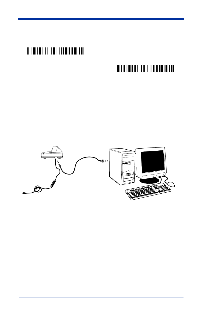
Connecting the Base with Serial Wedge
The IT2020 uses TTL signal levels to wedge into an RS-232 serial network. Use
only IT2020-5A serial wedge cables to prevent damage to the base. Refer to
Connecting the Base with RS-232 Serial Port on page 2-7 to set the baud rate
and communications protocol.
1. Turn off power to the computer.
2. Disconnect the existing serial cable from the computer.
3. Connect the appropriate interface cable to the base.
Note: For the base to work properly, you must have the correct cable for your
type of computer.
Other device
5
4
6
4. Plug the serial connector into the serial port on your computer. Tighten the two screws to secure the connector to the port.
5. Plug the other serial connector into the other device connection and tighten the two screws.
6. Plug the power supply barrel connector to the base, and plug the power supply into the AC source.
7. Once the base has been fully connected, power up the computer.
IMAGETEAM™ 2020/5620 System Manual 1 - 27
Page 44

To set up the serial wedge terminal ID, use the serial terminal ID 050 and follow
the instructions on page 2-1. Make sure that all of the communication
parameters match on all of the connected devices. Choosing Both sends
scanned data to P1 and P2. Default = P1.
* P1
P2
Both P1 and P2
1 - 28 IMAGETEAM™ 2020/5620 System Manual
Page 45

2
Terminal Interfaces
Terminal ID
If your interface is not a standard PC AT, refer to "Supported Terminals" on page
2-2 through page 2-3, and locate the Terminal ID number for your PC. Scan the
Terminal ID bar code below, then scan the numeric bar code(s) from the
Programming Chart inside the back cover of this manual to program the scanner
for your terminal ID. Scan Save to save your selection.
For example, an IBM AT terminal has a Terminal ID of 003. You would scan the
Terminal ID bar code, then 0, 0, 3 from the Programming Chart inside the back
cover of this manual, then Save. If you make an error while scanning the digits
(before scanning Save), scan the Discard code on the Programming Chart, scan
the Terminal ID bar code, scan the digits, and the Save code again.
Note: The default interface for the IT2020-5 is Keyboard Wedge (Term ID =
003).
Terminal ID
Save
Note: After scanning one of these codes, you must power cycle your computer.
IMAGETEAM™ 2020/5620 System Manual 2 - 1
Page 46

Supported Terminals
Ter minal Model(s) Terminal ID
DEC VT510, 520, 525 (PC style)
DEC VT510, 520, 525 (DEC style
LK411)
Esprit 200, 400
Heath Zenith PC, AT
HP Vectra
IBM XT
IBM PS/2 25, 30, 77DX2
IBM AT, PS/2 30–286, 50, 55SX, 60,
70, 70–061, 70–121, 80
IBM 102 key 3151, 3161, 3162, 3163, 3191,
3192, 3194, 3196, 3197, 3471,
3472, 3476, 3477
IBM 122 key 3191, 3192, 3471, 3472
IBM 122 key 3196, 3197, 3476, 3477, 3486,
3482, 3488
IBM 122 key 3180
IBM 122 key 3180 data entry keyboard
IBM DOS/V 106 key PC & Workstation
IBM SurePOS USB Hand Held Scanner
IBM SurePOS USB Tabletop Scanner
IBM Thinkpad 360 CSE, 340, 750
IBM Thinkpad
IBM Thinkpad 365, 755CV
I/O 122 key 2676D, 2677C, 2677D
ITT 9271
Lee Data IIS
NEC 98XX Series
Olivetti M19, M200
Olivetti M240, M250, M290, M380,
P500
RS-232 TTL
Serial Wedge
Silicon Graphics Indy, Indigoll
Telex 88 key 078, 078A, 79, 80, 191, 196,
1191,1192, 1471, 1472, 1476,
1477, 1483
Telex 88 key Data Entry Keyboard
Telex 102 key 078, 078A, 79, 80, 191, 196,
1191,1192, 1471, 1472, 1476,
1477, 1483
005
104
005
003*
003*
001
002
003*
006
007
008
024
114
102
128**
129**
097
106
003*
008
007
007
103
001
003*
000
050
005
025
112
045
2 - 2 IMAGETEAM™ 2020/5620 System Manual
Page 47

Supported Terminals (Continued)
Ter minal Model(s) Terminal ID
Telex 122 key 078, 078A, 79, 80, 191, 196,
USB PC Keyboard
USB Mac Keyboard
USB Com Port
USB HIDPOS
Wand Emulation (Code
39 Format)
Wand Emulation (Same
Code Format)
* Default for IT2020-5A.
**It is best to use the Plug and Play bar codes, beginning on page 1-25 to program these
interfaces, rather than scanning the terminal ID listed in this table.
1191,1192, 1471, 1472, 1476,
1477, 1482, 1483
046
124**
125**
130
131**
061
064
IMAGETEAM™ 2020/5620 System Manual 2 - 3
Page 48

Keyboard Country
Scan the appropriate country code below to program the keyboard for your
country. As a general rule, the following characters are supported, but need
special care for countries other than the United States:
@ | $ # { } [ ] = / ‘ \ < > ~
* United States
Denmark
France
Great Britain
Belgium
Finland
Germany/Austria
Italy
Norway
Spain
Switzerland
2 - 4 IMAGETEAM™ 2020/5620 System Manual
Page 49

Please refer to the Hand Held Products website (www.handheld.com) for
complete keyboard country support information and applicable interfaces. If you
need to program a keyboard for a country other than one listed above, scan the
Program Keyboard Country bar code below, then scan the numeric bar
code(s) for the appropriate country from the inside back cover, then the Save bar
code.
Program Keyboard Country
Keyboard Style
This programs keyboard styles, such as Caps Lock and Shift Lock.
Regular.
Regular
Caps Lock
Shift Lock
to U.S. keyboards).
Automatic Caps Lock
software tracks and reflects if you have Caps Lock on or off (AT and PS/2 only).
This selection can only be used with systems that have an LED which notes the
Caps Lock status.
Autocaps via NumLock
Germany, France) where the Caps Lock key cannot be used to toggle Caps
Lock. The NumLock option works similarly to the regular Auotcaps, but uses the
NumLock key to retrieve the current state of the Caps Lock.
is used when you normally have the Caps Lock key off.
* Regular
is used when you normally have the Caps Lock key on.
Caps Lock
is used when you normally have the Shift Lock key on (not common
Shift Lock
is used if you change the Caps Lock key on and off. The
Automatic Caps Lock
bar code should be scanned in countries (e.g.,
Default =
Autocaps via NumLock
IMAGETEAM™ 2020/5620 System Manual 2 - 5
Page 50

Emulate External Keyboard
keyboard (IBM AT or equivalent).
Note: After scanning the Emulate External Keyboard bar code, you must power
cycle your computer.
should be scanned if you do not have an external
Emulate External Keyboard
Keyboard Modifiers
This modifies special keyboard features, such as CTRL+ ASCII codes and Turbo
Mode.
Control + ASCII Mode On:
control characters for values 00-1F. Refer to Keyboard Function
Relationships, page 7-1 for CTRL+ ASCII Values.
Control + ASCII Mode On
Turbo Mode:
drops characters, do not use Turbo Mode.
Numeric Keypad Mode:
numeric keypad.
Numeric Keypad Mode On
The scanner sends characters to a terminal faster. If the terminal
Turbo Mode On
Default = Off
The scanner sends key combinations for ASCII
Default = Off
* Control + ASCII Mode Off
Default = Off
* Turbo Mode Off
Sends numeric characters as if entered from a
* Numeric Keypad Mode Off
2 - 6 IMAGETEAM™ 2020/5620 System Manual
Page 51
Automatic Direct Connect Mode:
IBM AT style terminal and the system is dropping characters.
Automatic Direct
Connect Mode On
This selection can be used if you have an
Default = Off
* Automatic Direct Connect
Mode Off
Connecting the Base with RS-232 Serial Port
1. Turn off power to the terminal/computer.
2. Connect the appropriate interface cable to the base.
Note: For the base to work properly, you must have the correct cable for your
type of terminal/computer.
3
2
4
5
3. Plug the serial connector into the serial port on your computer. Tighten the two screws to secure the connector to the port.
4. Plug the power supply barrel connector to the base, and plug the power supply into the AC source.
5. Once the base has been fully connected, power up the computer.
IMAGETEAM™ 2020/5620 System Manual 2 - 7
Page 52

All communication parameters between the scanner and terminal must match for
correct data transfer through the serial port using RS-232 protocol. Scanning the
RS-232 interface bar code, programs the scanner for an RS-232 interface at
115,200 baud, parity–none, 8 data bits, 1 stop bit, and adds a suffix of a CR LF.
RS-232 Interface
RS-232 Baud Rate
Baud Rate sends the data from the scanner to the terminal at the specified rate.
The host terminal must be set for the same baud rate as the scanner.
Default = 115,200
.
300
600
1200
2400
4800
9600
19200
38400
57,600
* 115,200
2 - 8 IMAGETEAM™ 2020/5620 System Manual
Page 53

RS-232 Word Length: Data Bits, Stop Bits, and Parity
Data Bits
application requires only ASCII Hex characters 0 through 7F decimal (text, digits,
and punctuation), select 7 data bits. For applications which require use of the full
ASCII set, select 8 data bits per character.
Stop Bits
Parity
Default = None.
sets the word length at 7 or 8 bits of data per character. If an
Default = 8.
sets the stop bits at 1 or 2.
provides a means of checking character bit patterns for validity.
7 Data, 1 Stop, Parity Even
7 Data, 1 Stop, Parity Odd
7 Data, 2 Stop Parity None
8 Data, 1 Stop, Parity Even
Default = 1.
7 Data, 1 Stop, Parity None
7 Data, 2 Stop, Parity Even
7 Data, 2 Stop, Parity Odd
* 8 Data, 1 Stop, Parity None
8 Data, 1 Stop, Parity Odd
IMAGETEAM™ 2020/5620 System Manual 2 - 9
Page 54

RS-232 Handshaking
RS-232 Handshaking allows control of data transmission from the Imager using
software commands from the host device. CTS/RTS operates in mode 2. When
this feature is turned
is turned On, the host device suspends transmission by sending the XOFF
character (DC3, hex 13) to the Imager. To resume transmission, the host sends
the XON character (DC1, hex 11). Data transmission continues where it left off
when XOFF was sent.
RTS/CTS On
XON/XOFF On
ACK/NAK On
Off
, no data flow control is used. When Data Flow Control
Default = RTS/CTS, XON/XOFF and ACK/NAK Off.
* RTS/CTS Off
* XON/OFF Off
* ACK/NAK Off
Host ACK Selection
Some applications require that the host terminal (or server) approve or reject
incoming bar code data and notify the operator of these actions. These
applications require that the host maintain control over the response indicators
emitted from the source scanner. Turning the Host ACK selection on, configures
the cordless system scanners to respond to commands from the host system.
The following criteria must be met for the Host ACK to work correctly:
• The cordless system must be configured for “Host Port RS-232” (Terminal ID
= 000)
• RTS/CTS is defaulted off. You must enable it if the host system requires it.
• Host ACK must be enabled (page 2-11).
• System performance degrades when using Host ACK at rates lower than
9600.
• The host terminal software must be capable of interpreting the bar code data,
make decisions based on the data content, and send out appropriate escape
commands to the source scanner.
Escape commands are addressed to the source scanner via “Application Work
Groups.” Once a command is sent, all scanners in a group respond to that
command. Because of this situation, it is recommended that each scanner is
assigned to its own group in host ACK mode.
2 - 10 IMAGETEAM™ 2020/5620 System Manual
Page 55

The commands to which the scanner responds are listed on page 2-12. The
<ESC> is a 1B in hex. A typical command string is y <ESC> x, where “y” is the
application work group number, “<ESC> x” is the escape command, and the
comma is the terminator
Commands may be strung together to create custom response sequences. An
example of a command string is listed below.
0<ESC>4<ESC>5<ESC>6,
The above example will make a scanner in application work group zero beep low,
medium, high.
Once Host ACK is enabled, the system works as follows:
• The scanner reads a code and sends data to the base/host system. No
audible or visual indication is emitted until you receive an escape command.
The scanner read illumination goes out upon a successful read.
• Scanner is suspended until 1) a valid escape string is received from the host
system (via the base) or 2) the scanner “times out.”
• Once condition 1 or 2 above has been met, the scanner is ready to scan
again, and the process repeats.
Time out is indicated by three rapid beeps at the same pitch. A time out occurs
if the source scanner does not receive a valid escape command in 10 seconds.
If a time out occurs, the operator should check the host system to understand
why a response to the scanner was not received.
.
Host ACK Enable
Host ACK On
* Host ACK Off
IMAGETEAM™ 2020/5620 System Manual 2 - 11
Page 56

IT2020-5 Host Escape Commands
Command Action
<ESC> a Indicate as if successful menu change made
<ESC> b Indicate as if unsuccessful menu change made
<ESC> 1
<ESC> 2
<ESC> 3
<ESC> 4 One beep at low volume
<ESC> 5 One beep at medium volume
<ESC> 6 One beep at high volume
<ESC> 7 Indicate as successful decode and communication to host.
<ESC> 8 Indicate as unsuccessful decode and communication to host.
o
G
)
1
Illuminate green LED for 135 milliseconds (followed by at least 70 mSecs.
dark time when multiple blinks)
Illuminate green LED for two seconds (followed by at least 500 mSecs.
dark time when multiple blinks)
Illuminate green LED for five seconds (followed by at least 500 mSecs.
dark time when multiple blinks)
s
d
n
e
s
e
s
a
B
)
d
a
e
R
d
o
a
c
S
o
t
e
s
a
B
:
K
C
A
)
4
C
)
A
3
2
a
d
r
e
n
n
t
o
t
s
o
H
:
K
t
s
o
h
o
t
a
t
e
s
a
B
2 - 12 IMAGETEAM™ 2020/5620 System Manual
Page 57

Wand Emulation
Wand Emulation Connection
The Wand Emulation Connection bar codes should be used if you want to
change the terminal ID
recommend using Wand Emulation Plug & Play bar codes to program your
imager to emulate a wand reader. The Wand Emulation Plug & Play bar codes
change other parameters, in addition to changing the terminal ID. Please refer
to Wand Emulation Plug & Play on page 1-22 for further information.
In Wand Emulation mode, the imager decodes the bar code then sends data in
the same format as a wand imager. The Code 39 Format converts all
symbologies to Code 39.
The Same Code Format transmits UPC, EAN, Code 128 and Interleaved 2 of 5
without any changes, but converts all other symbologies to Code 39. 2D
symbologies are converted to Code 128.
Code 39 Format
The
Code Format
bar code sets the terminal ID to 64.
Code 39 Format
only
, without changing any other imager settings. We
bar code below sets the terminal ID to 61, and the
Same Code Format
Same
IMAGETEAM™ 2020/5620 System Manual 2 - 13
Page 58

Wand Emulation Transmission Rate
The transmission rate is limited by the terminal’s ability to receive data without
dropping characters.
Default = 25 inches/second.
10
* 25
40
80
120
150
200
Wand Emulation Polarity
The Polarity can be sent as standard with black bars high, or reversed with white
bars high.
Default = Black High.
* Black High
White High
2 - 14 IMAGETEAM™ 2020/5620 System Manual
Page 59

Wand Emulation Idle
The idle describes the state of the scanner when no data is being transmitted.
When in Wand Emulation mode, you must set the scanner’s idle state to match
the idle state for the device to which the scanner is connected.
High
.
* Idle High
Default = Idle
Idle Low
Wand Emulation Data Block Size
This transmits the data in smaller blocks to prevent buffer overflow.
20
* 40
60
80
Wand Emulation Delay Between Blocks
This sets the delay time between data blocks.
5ms
150ms
Default = 50ms.
* 50ms
500ms
Default = 40.
IMAGETEAM™ 2020/5620 System Manual 2 - 15
Page 60

Wand Emulation Overall Checksum
When this option is turned on, a computed check character is added at the end
of the entire message. The check character is the character which when
Exclusive-OR’d with every preceding character of the message yields a result of
0x00 (00H).
Wand Emulation Overall
Default = Off.
Checksum On
* Wand Emulation Overall
Checksum Off
2 - 16 IMAGETEAM™ 2020/5620 System Manual
Page 61

3
Output
Scanner Functions
Good Read Indicators
Beeper – Good Read
The beeper may be programmed On or Off in response to a good read. Turning
this option off, only turns off the beeper response to a good read indication. All
error and menu beeps are still audible.
* Beeper - Good Read On
Beeper Volume – Good Read
The beeper volume codes modify the volume of the beep the scanner emits on
a good read.
Default = Medium.
Default = On.
Beeper - Good Read Off
Low
* Medium
High
Off
IMAGETEAM™ 2020/5620 System Manual 3 - 1
Page 62

Beeper Pitch – Good Read
The beeper pitch codes modify the pitch (frequency) of the beep the scanner
emits on a good read.
Low (1600 Hz)
High (4200 Hz)
Default = Medium.
* Medium (3250 Hz)
Beeper Duration – Good Read
The beeper duration codes modify the length of the beep the scanner emits on a
good read.
Default = Normal.
* Normal Beep
Short Beep
LED – Good Read
The LED indicator can be programmed On or Off in response to a good read.
Default = On.
*LED - Good Read On
LED - Good Read Off
3 - 2 IMAGETEAM™ 2020/5620 System Manual
Page 63

Number of Beeps – Good Read
The number of beeps of a good read can be programmed from 1 - 9. The same
number of beeps will be applied to the beeper and LED in response to a good
read. For example, if you program this option to have five beeps, there will be
five beeps and five LED flashes in response to a good read. The beeps and LED
flashes are in sync with one another. To change the number of beeps, scan the
bar code below and then scan a digit (1-9) bar code and the Save bar code on
the Programming Chart inside the back cover of this manual.
Number of Beeps/LED Flashes
Default = One.
Good Read Delay
This sets the minimum amount of time before the scanner can read another bar
code.
Default = 0 ms (No Delay.
* No Delay
Medium Delay (1000 ms)
)
Short Delay (500 ms)
Long Delay (1500 ms)
User-Specified Good Read Delay
If you want to set your own length for the good read delay, scan the bar code
below, then set the delay (from 0-30,000 milliseconds) by scanning digits from
the inside back cover, then scanning
User-Specified Good Read Delay
IMAGETEAM™ 2020/5620 System Manual 3 - 3
Save
.
Page 64

Scanner Trigger Modes
Manual/Serial Trigger, Low Power
You can activate the scanner either by pressing the trigger, or using a serial
trigger command (see "Trigger Commands" on page 10-4). When in manual
trigger mode, the scanner scans until a bar code is read, or until the trigger is
released.
When in serial mode, the scanner scans until a bar code has been read or until
the deactivate command is sent. In serial mode, the scanner can also be set to
turn itself off after a specified time has elapsed (see Read Time-Out (Serial
Trigger Mode), which follows).
* Manual/Serial Trigger
Read Time-Out (Serial Trigger Mode)
Use this selection to set a time-out (in milliseconds) of the scanner’s trigger when
using serial commands to trigger the scanner. Once the scanner has timed out,
you can activate the scanner either by pressing the trigger or using a serial
trigger command. After scanning the Read Time-Out bar code, set the time-out
duration (from 0-300,000 milliseconds) by scanning digits on the Programming
Chart inside the back cover, then scanning Save.
Read Time-Out
Default = 300,000 ms.
Scanner Power Time-Out Timer
Note: The Scanner Power Time-out Timer option only applies to Manual/Serial
Trigger.
When there is no activity within a specified time period, the scanner enters low
power mode. Scan the appropriate Imager Power Time-Out bar code to change
the time-out duration (in seconds).
3 - 4 IMAGETEAM™ 2020/5620 System Manual
Page 65

Note: Scanning zero (0) is the equivalent of setting no time-out.
If there are no trigger pulls during the “scanner power time-out timer” interval, the
scanner goes into power down mode. Whenever the trigger is enabled, the
“scanner power time-out timer” is reset. If the scanner is placed in the IT20205A cradle and the battery is in the process of being charged, the scanner will not
go into power down mode.
0 seconds
200 seconds
400 seconds
900 seconds
* 3600 seconds
7200 seconds
Note: When the scanner is in power down mode, pull the trigger to power the
unit back up. There will be a set of power up beeps and a delay of up to
a few seconds for the radio to join. The scanner will then be ready to use.
Automatic Trigger
The scanner scans continuously at full power with illumination fully on.
Automatic Trigger
Presentation Mode
The LEDs are off until a bar code is presented to the scanner. Then the LEDs
turn on automatically to read the code. Presentation Mode uses ambient light to
detect the bar codes. If the light level in the room is not high enough,
Presentation Mode will not work properly.
Presentation Mode
IMAGETEAM™ 2020/5620 System Manual 3 - 5
Page 66

Hands Free Time-Out
The Automatic Trigger and Presentation Modes are referred to as “hands free”
modes. If the imager’s trigger is pulled when using a hands free mode, the
imager changes to manual trigger mode. You can set the time the imager should
remain in manual trigger mode by setting the Hands Free Time-Out. Once the
time-out value is reached, (if there have been no further trigger pulls) the imager
reverts to the original hands free mode.
Scan the
0-300,000 milliseconds) from the inside back cover, and
ms.
Hands Free Time-Out
bar code, then scan the time-out duration (from
Hands Free Time-Out
Save
.
Default = 5,000
Reread Delay
This sets the time period before the scanner can read the
second time. Setting a reread delay protects against accidental rereads of the
same bar code. Longer delays are effective in minimizing accidental rereads at
POS (point of sale). Use shorter delays in applications where repetitive bar code
scanning is required.
Reread Delay only works when in automatic trigger mode (see page 3-5).
Short (500 ms)
Long (1000 ms)
Default = Medium.
Extra Long (2000 ms)
same
bar code a
* Medium (750 ms)
User-Specified Reread Delay
If you want to set your own length for the reread delay, scan the bar code below,
then set the delay (from 0-30,000 milliseconds) by scanning digits from the inside
back cover, then scanning
Save
.
User-Specified Reread Delay
3 - 6 IMAGETEAM™ 2020/5620 System Manual
Page 67

Centering Window
Use the centering feature to narrow the scanner’s field of view so the scanner
reads only the bar code you want. When centering is turned on, the scanner only
reads codes that intersect or are contained within the centering window you set
up. At least part of a bar code must be within the window to be decoded or output
by the scanner.
To change the left or right edge of the centering window, scan Centering On, then
scan one of the following bar codes. Then scan the percent you want to shift the
centering window using digits on the inside back cover of this manual. Scan
Save. Default Centering = 40% for Left, 60% for Right.
Centering On
* Centering Off
Left of Centering Window
Right of Centering Window
The figure below illustrates the percentage range from 1 to 100%.
40% 60%
30%
20%
10%
0%
70%
80%
90%
100%
IMAGETEAM™ 2020/5620 System Manual 3 - 7
Page 68

Example: If you have two bar codes next to one another and the centering
window is set to 40% left edge and 60% right edge, only the bar
code that intersects that window will be decoded.
Decoded bar code
40% 60%
30%
20%
10%
70%
80%
90%
0%
100%
Output Sequence Overview
Require Output Sequence
When turned off, the bar code data will be output to the host as the scanner
decodes it. When turned on, all output data must conform to an edited sequence
or the scanner will not transmit the output data to the host device.
Note: This selection is unavailable when the Multiple Symbols Selection is
turned on.
Output Sequence Editor
This programming selection allows you to program the scanner to output data
(when scanning more than one symbol) in whatever order your application
requires, regardless of the order in which the bar codes are scanned. Reading
Default Sequence
the
shown below. These are the defaults. Be certain you want to delete or clear all
formats before you read the
Note: To make Output Sequence Editor selections, you’ll need to know the code
I.D., code length, and character match(es) your application requires. Use
the Alphanumeric symbols (inside back cover) to read these options.
To Add an Output Sequence
1. Scan the
2. Code I.D.
On the Symbology Chart on page A-1, find the symbology to which you want
to apply the output sequence format. Locate the Hex value for that symbology and scan the 2 digit hex value from the Programming Chart inside the
back cover of this manual.
Enter Sequence
symbol programs the scanner to the Universal values,
Default Sequence
symbol (see Multiple Symbols, page 3-12).
symbol.
3 - 8 IMAGETEAM™ 2020/5620 System Manual
Page 69

3. Length
Specify what length (up to 9999 characters) of data output will be acceptable
for this symbology. Scan the four digit data length from the Programming
Chart inside the back cover of this manual. (Note: 50 characters is entered
as 0050. 9999 is a universal number, indicating all lengths.) When calculating the length, you must count any programmed prefixes, suffixes, or formatted characters as part of the length (unless using 9999).
4. Character Match Sequences
On the ASCII Conversion Chart (Code Page 1252), page A-2, find the Hex
value that represents the character(s) you want to match. Use the Program-
ming Chart inside the back cover of this manual to read the alphanumeric
combination that represents the ASCII characters. (99 is the Universal number, indicating all characters.)
5. End Output Sequence Editor
Other Programming Selections
F F
Scan
to save your entries.
•
to enter an Output Sequence for an additional symbology, or
Discard
This exits without saving any Output Sequence changes.
Output Sequence Editor
Enter Sequence
Default Sequence
Save
Require Output Sequence
When an output sequence is
sequence or the scanner will not transmit the output data to the host device.
When it’s
conform to an edited sequence, but if it cannot, the scanner transmits all output
data to the host device as is.
When the output sequence is
scanner decodes it.
On/Not Required
IMAGETEAM™ 2020/5620 System Manual 3 - 9
Required
, the scanner will attempt to get the output data to
Off
, all output data must conform to an edited
, the bar code data is output to the host as the
Page 70

Note: This selection is unavailable when the Multiple Symbols Selection is
turned on.
Required
On/Not Required
* Off
Output Sequence Example
In this example, you are scanning Code 93, Code 128, and Code 39 bar codes,
but you want the scanner to output Code 39 1st, Code 128 2nd, and Code 93
3rd, as shown below.
Note: Code 93 must be enabled to use this example.
A - Code 39
B - Code 128
C - Code 93
You would set up the sequence editor with the following command line:
SEQBLK62999941FF6A999942FF69999943FF
The breakdown of the command line is shown below:
SEQBLKsequence editor start command
62 code identifier for Code 39
9999 code length that must match for Code 39, 9999 = all lengths
3 - 10 IMAGETEAM™ 2020/5620 System Manual
Page 71

41 start character match for Code 39, 41h = “A”
FF termination string for first code
6A code identifier for Code 128
9999 code length that must match for Code 128, 9999 = all lengths
42 start character match for Code 128, 42h = “B”
FF termination string for second code
69 code identifier for Code 93
9999 code length that must match for Code 93, 9999 = all lengths
43 start character match for Code 93, 43h = “C”
FF termination string for third code
To program the previous example using specific lengths, you would have to
count any programmed prefixes, suffixes, or formatted characters as part of the
length. If you use the example on page 3-10, but assume a <CR> suffix and
specific code lengths, you would use the following command line:
SEQBLK62001241FF6A001342FF69001243FF
The breakdown of the command line is shown below:
SEQBLK sequence editor start command
62 code identifier for Code 39
0012 A - Code 39 sample length (11) plus CR suffix (1) = 12
41 start character match for Code 39, 41h = “A”
FF termination string for first code
6A code identifier for Code 128
0013 B - Code 128 sample length (12) plus CR suffix (1) = 13
42 start character match for Code 128, 42h = “B”
FF termination string for second code
69 code identifier for Code 93
0012 C - Code 93 sample length (11) plus CR suffix (1) = 12
43 start character match for Code 93, 43h = “C”
FF termination string for third code
IMAGETEAM™ 2020/5620 System Manual 3 - 11
Page 72

Multiple Symbols
When this programming selection is turned On, it allows you to read multiple
symbols with a single pull of the scanner’s trigger. If you press and hold the
trigger, aiming the scanner at a series of symbols, it reads unique symbols once,
beeping (if turned on) for each read. The scanner attempts to find and decode
new symbols as long as the trigger is pulled. When this programming selection
is turned
Off
, the scanner will only read the symbol closest to the aiming beam.
Multiple Symbols On
* Multiple Symbols Off
No Read
With No Read turned On, the scanner sends an “NR” to the host if you pull and
release the trigger without reading a code (e.g., bad bar code). If No Read is
Off
turned
If you want a different notation than “NR,” for example, “Error,” or “Bad Code,”
you can edit the output message using the Data Formatter (page 5-5). The hex
code for the No Read symbol is 9C.
, the “NR” will not be sent to the host.
No Read On
* No Read Off
Video Reverse
Video Reverse is used to allow the scanner to read bar codes that are inverted.
The “Off” bar code below is an example of this type of bar code.
Note: If additional menuing is required, Video Reverse must be disabled to read
the menu bar codes and then re-enabled after menuing is completed.
Video Reverse On
* Video Reverse Off
3 - 12 IMAGETEAM™ 2020/5620 System Manual
Page 73

4
Data Editing
Prefix/Suffix Overview
When a bar code is scanned, additional information is sent to the host computer
along with the bar code data. This group of bar code data and additional,
user-defined data is called a “message string.” The selections in this section are
used to build the user-defined data into the message string.
Prefix and Suffix characters are data characters that can be sent before and after
scanned data. You can specify if they should be sent with all symbologies, or
only with specific symbologies. The following illustration shows the breakdown
of a message string:
Prefix
alpha numeric &
control characters
Scanned Data
variable length1-11
Suffix
1-11
alpha numeric &
control characters
Points to Keep In Mind
• It is not necessary to build a message string. The selections in this chapter
are only used if you wish to alter the default settings.
Default suffix = None
• A prefix or suffix may be added or cleared from one symbology or all
symbologies.
• You can add any prefix or suffix from the ASCII Conversion Chart (Code Page
1252) on page A-2, plus Code I.D. and AIM I.D.
• You can string together several entries for several symbologies at one time.
• Enter prefixes and suffixes in the order in which you want them to appear on
the output.
• When setting up for specific symbologies (as opposed to all symbologies), the
specific symbology ID value counts as an added prefix or suffix character.
.
Default prefix = None.
IMAGETEAM™ 2020/5620 System Manual 4 - 1
Page 74

To Add a Prefix or Suffix:
Step 1. Scan the Add Prefix or Add Suffix symbol (page 4-3).
Step 2. Determine the 2 digit Hex value from the Symbology Chart (included in
the Appendix A) for the symbology to which you want to apply the prefix
or suffix. For example, for Code 128, Code ID is “j” and Hex ID is “6A”.
Step 3. Scan the 2 hex digits from the Programming Chart inside the back
cover of this manual or scan 9, 9 for all symbologies.
Step 4. Determine the hex value from the ASCII Conversion Chart (Code Page
1252) on page A-2, for the prefix or suffix you wish to enter.
Step 5. Scan the 2 digit hex value from the Programming Chart inside the back
cover of this manual.
Step 6. Repeat Steps 4 and 5 for every prefix or suffix character.
Step 7. To add the Code I.D., scan 5, C, 8, 0.
To add AIM I.D., scan 5, C, 8, 1.
To add a backslash (\), scan 5, C, 5, C.
Note: To add a backslash (\) as in Step 7, you must scan 5C twice – once to
create the leading backslash and then to create the backslash itself.
Step 8. Scan Save to exit and save, or scan Discard to exit without saving.
Repeat Steps 1-6 to add a prefix or suffix for another symbology.
Example: Add a Suffix to a specific symbology
To send a CR (carriage return)Suffix for UPC only:
Step 1. Scan Add Suffix.
Step 2. Determine the 2 digit hex value from the Symbology Chart (included in
the Appendix A) for UPC.
Step 3. Scan 6, 3 from the Programming Chart inside the back cover of this
manual.
Step 4. Determine the hex value from the ASCII Conversion Chart (Code Page
1252) on page A-2, for the CR (carriage return).
Step 5. Scan 0, D from the Programming Chart inside the back cover of this
manual.
Step 6. Scan Save, or scan Discard to exit without saving.
4 - 2 IMAGETEAM™ 2020/5620 System Manual
Page 75

To Clear One or All Prefixes or Suffixes:
You can clear a single prefix or suffix, or clear all prefixes/suffixes for a
symbology. When you Clear One Prefix (Suffix), the specific character you
select is deleted from the symbology you want. When you Clear All Prefixes
(Suffixes), all the prefixes or suffixes for a symbology are deleted.
Step 1. Scan the Clear One Prefix or Clear One Suffix symbol.
Step 2. Determine the 2 digit Hex value from the Symbology Chart (included in
the Appendix A) for the symbology from which you want to clear the prefix or suffix.
Step 3. Scan the 2 digit hex value from the Programming Chart inside the back
cover of this manual or scan 9, 9 for all symbologies.
Your change is automatically saved.
To Add a Carriage Return Suffix to all Symbologies
Scan the following bar code if you wish to add a carriage return suffix to all
symbologies at once. This action first clears all current suffixes, then programs
a carriage return suffix for all symbologies.
Add CR Suffix
All Symbologies
Prefix Selections
Add Prefix
Clear One Prefix
Clear All Prefixes
IMAGETEAM™ 2020/5620 System Manual 4 - 3
Page 76

Suffix Selections
Add Suffix
Clear One Suffix
Clear All Suffixes
Function Code Transmit
When this selection is enabled and function codes are contained within the
scanned data, the scanner transmits the function code to the terminal. Charts of
these function codes are provided in Supported Interface Keys starting on
page 7-3. When the scanner is in keyboard wedge mode, the scan code is
converted to a key code before it is transmitted.
* Enable
Default = Enable.
Disable
Intercharacter, Interfunction, and Intermessage Delays
Some terminals drop information (characters) if data comes through too quickly.
Intercharacter, interfunction, and intermessage delays slow the transmission of
data, increasing data integrity.
Each delay is composed of a 5 millisecond step. You can program up to 99 steps
(of 5 ms each) for a range of 0-495 ms.
4 - 4 IMAGETEAM™ 2020/5620 System Manual
Page 77

Intercharacter Delay
An intercharacter delay of up to 495 milliseconds may be placed between the
transmission of each character of scanned data. Scan the Intercharacter Delay
bar code below, then scan the number of milliseconds and the SAVE bar code
using the Programming Chart inside the back cover of this manual.
Prefix Scanned Data Suffix
1 234 5
Intercharacter Delay
Intercharacter Delay
To remove this delay, scan the Intercharacter Delay bar code, then set the
number of steps to 0. Scan the SAVE bar code using the Programming Chart
inside the back cover of this manual.
Note: Intercharacter delays are not supported in USB serial emulation.
User Specified Intercharacter Delay
An intercharacter delay of up to 495 milliseconds may be placed after the
transmission of a particular character of scanned data. Scan the Delay Length
bar code below, then scan the number of milliseconds and the SAVE bar code
using the Programming Chart inside the back cover of this manual.
Next, scan the Character to Trigger Delay bar code, then the 2-digit hex value
for the ASCII character that will trigger the delay ASCII Conversion Chart (Code
Page 1252) on page A-2.
Delay Length
Character to Trigger Delay
To remove this delay, scan the Delay Length bar code, and set the number of
steps to 0. Scan the SAVE bar code using the Programming Chart inside the
back cover of this manual.
IMAGETEAM™ 2020/5620 System Manual 4 - 5
Page 78
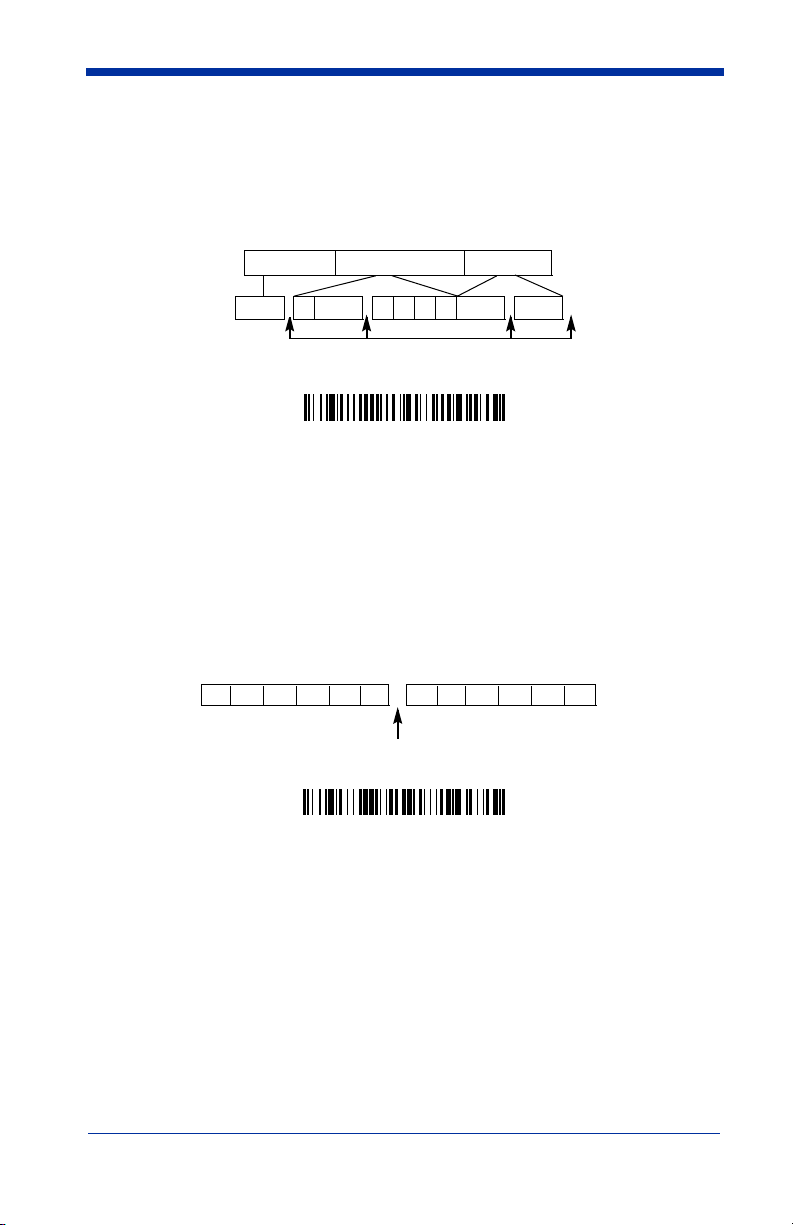
Interfunction Delay
An interfunction delay of up to 495 milliseconds may be placed between the
transmission of each segment of the message string. Scan the Interfunction
Delay bar code below, then scan the number of milliseconds and the SAVE bar
code using the Programming Chart inside the back cover of this manual.
Prefix Scanned Data Suffix
1 2345STX HT CR LF
Interfunction Delays
Interfunction Delay
To remove this delay, scan the Interfunction Delay bar code, then set the
number of steps to 0. Scan the SAVE bar code using the Programming Chart
inside the back cover of this manual.
Intermessage Delay
An intermessage delay of up to 495 milliseconds may be placed between each
scan transmission. Scan the Intermessage Delay bar code below, then scan
the number of milliseconds and the SAVE bar code using the Programming
Chart inside the back cover of this manual.
2nd Scan Transmission1st Scan Transmission
Intermessage Delay
Intermessage Delay
To remove this delay, scan the Intermessage Delay bar code, then set the
number of steps to 0. Scan the SAVE bar code using the Programming Chart
inside the back cover of this manual.
4 - 6 IMAGETEAM™ 2020/5620 System Manual
Page 79

5
Data Formatting
Data Format Editor Introduction
You may use the Data Format Editor to change the scanner’s output. For
example, you can use the Data Format Editor to insert characters at certain
points in bar code data as it is scanned. The selections in the following pages
are used only if you wish to alter the output.
Normally, when you scan a bar code, it gets outputted automatically; however
when you do a format, you must use a “send” command (see Send Commands
on page 5-2) within the format program to output data.
Multiple formats may be programmed into the scanner. They are stacked in the
order in which they are entered. However, the following list presents the order
in which formats are applied:
1. Specific Term ID, Actual Code ID, Actual Length
2. Specific Term ID, Actual Code ID, Universal Length
3. Specific Term ID, Universal Code ID, Actual Length
4. Specific Term ID, Universal Code ID, Universal Length
5. Universal Term ID, Actual Code ID, Actual Length
6. Universal Term ID, Actual Code ID, Universal Length
7. Universal Term ID, Universal Code ID, Actual Length
8. Universal Term ID, Universal Code ID, Universal Length
Default Data Format setting = None.
If you have changed data format settings, and wish to clear all formats and return
to the factory defaults, scan the Default Data Format code on page 5-4.
To Add a Data Format
Step 1. Scan the Enter Data Format symbol (page 5-4).
Step 2. Primary/Alternate Format
Determine if this will be your primary data format, or one of 3 alternate
formats. (Alternate formats allow you “single shot” capability to scan
one bar code using a different data format. After the one bar code has
been read, the scanner reverts to the primary data format. See page 5-
5.) If you are programming the primary format, scan 0 using the Programming Chart inside the back cover of this manual. If you are pro-
gramming an alternate format, scan 1, 2, or 3, depending on the
alternate format you are programming.
Step 3. Terminal Type
IMAGETEAM™ 2020/5620 System Manual 5 - 1
Refer to the Supported Terminals Chart (page 2-2) and locate the Terminal ID number for your PC. Scan three numeric bar codes on the
inside back cover to program the scanner for your terminal ID (you must
enter 3 digits). For example, scan 0 0 3 for an AT wedge.
Page 80

Note: The wildcard for all terminal types is 099.
Step 4. Code I.D.
In the Appendix A, find the symbology to which you want to apply the
data format. Locate the Hex value for that symbology and scan the 2
digit hex value from the Programming Chart inside the back cover of
this manual.
Step 5. Length
Specify what length (up to 9999 characters) of data will be acceptable
for this symbology. Scan the four digit data length from the Program-
ming Chart inside the back cover of this manual. (Note: 50 characters is
entered as 0050. 9999 is a universal number, indicating all lengths.)
Step 6. Editor Commands
Refer to the Format Editor Commands Chart (page 5-2). Scan the sym-
bols that represent the command you want to enter. 94 alphanumeric
characters may be entered for each symbology data format.
Step 7. Scan Save from the Programming Chart inside the back cover of this
manual to save your entries.
Other Programming Selections
• Clear One Data Format
This deletes one data format for one symbology. If you are clearing the
primary format, scan 0 from the Programming Chart inside the back cover of
this manual. If you are clearing an alternate format, scan 1, 2, or 3, depending
on the alternate format you are clearing. Scan the Terminal Type (refer to the
Supported Terminals Chart on page 2-2), Code I.D. (refer to the Symbology
Chart on page A-1), and the bar code data length for the specific data format
that you want to delete. All other formats remain unaffected.
• Save from the Programming Chart inside the back cover of this manual
This exits, saving any Data Format changes.
• Discard from the Programming Chart inside the back cover of this manual
This exits without saving any Data Format changes.
Data Format Editor Commands
Send Commands
F1 Send all characters followed by “xx” key or function code, starting from cur-
rent cursor position.
ASCII code, see ASCII Conversion Chart (Code Page 1252) on page A-2.)
F2 Send “nn” characters followed by “xx” key or function code, starting from
current cursor position.
(00-99) for the number of characters and xx stands for the hex value for an
ASCII code. See ASCII Conversion Chart (Code Page 1252) on page A-2.)
F3 Send up to but not including “ss” character (Search and Send) starting from
current cursor position, leaving cursor pointing to “ss” character followed by
“xx” key or function code.
5 - 2 IMAGETEAM™ 2020/5620 System Manual
Syntax = F1xx
Syntax = F2nnxx
Syntax = F3ssxx
(xx stands for the hex value for an
(nn stands for the numeric value
(ss and xx both stand for the
Page 81

hex values for ASCII codes, see ASCII Conversion Chart (Code Page
1252) on page A-2.)
F4 Send “xx” character “nn” times (Insert) leaving cursor in current cursor posi-
E9 Send all but the last “nn” characters, starting from the current cursor posi-
Syntax = F4xxnn
tion.
ASCII Conversion Chart (Code Page 1252) on page A-2, and nn is the
numeric value (00-99) for the number of times it should be sent.)
Syntax = E9nn
tion.
characters that will not be sent at the end of the message.)
(xx stands for the hex value for an ASCII code, see
(nn is the numeric value (00-99) for the number of
Move Commands
F5 Move the cursor ahead “nn” characters from current cursor position.
Syntax = F5nn
characters the cursor should be moved ahead.)
F6 Move the cursor back “nn” characters from current cursor position.
Syntax = F6nn
characters the cursor should be moved back.)
F7 Move the cursor to the beginning of the data string.
EA Move the cursor to the end of the data string.
(nn stands for the numeric value (00-99) for the number of
(nn stands for the numeric value (00-99) for the number of
Syntax = F7.
Syntax = EA
Search Commands
F8 Search ahead for “xx” character from current cursor position, leaving cursor
pointing to “xx” character.
an ASCII code, see ASCII Conversion Chart (Code Page 1252) on page A-
2.)
F9 Search back for “xx” character from current cursor position, leaving cursor
pointing to “xx” character.
an ASCII code, see ASCII Conversion Chart (Code Page 1252) on page A-
2.)
E6 Search ahead for the first non “xx” character from the current cursor posi-
tion, leaving cursor pointing to non “xx” character.
stands for the hex value for an ASCII code, see ASCII Conversion Chart
(Code Page 1252) on page A-2.
E7 Search back for the first non “xx” character from the current cursor position,
leaving cursor pointing to non “xx” character.
the hex value for an ASCII code, see ASCII Conversion Chart (Code Page
1252) on page A-2.)
Syntax = F8xx
Syntax = F9xx
(xx stands for the hex value for
(xx stands for the hex value for
Syntax = E6xx
Syntax = E7xx
(xx
(xx stands for
Miscellaneous Commands
FB Suppress all occurrences of up to 15 different characters, starting at the cur-
rent cursor position, as the cursor is advanced by other commands. When
the FC command is encountered, the suppress function is terminated. The
cursor is not moved by the FB command. Syntax = FBnnxxyy . .zz where
nn is a count of the number of suppressed characters in the list and xxyy ..
zz is the list of characters to be suppressed. (xx stands for the hex value for
an ASCII code, see ASCII Conversion Chart (Code Page 1252) on page A-
2.)
FC Disables suppress filter and clear all suppressed characters.
Syntax = FC.
IMAGETEAM™ 2020/5620 System Manual 5 - 3
Page 82

E4 Replaces up to 15 characters in the data string with user specified charac-
ters. Replacement continues until the E5 command is encountered.
tax = E4nnxx
1xx2yy1yy2
...zz1zz
characters to be replaced plus replacement characters; xx
ters to be replaced and xx
through zz
and zz2.
1
2
E5 Terminates character replacement.
where nn is the total count of both
2
1
defines replacement characters, continuing
Syntax = E5.
defines charac-
Syn-
FE Compare character in current cursor position to the character “xx.” If char-
acters are equal, increment cursor. If characters are not equal, no format
match.
Syntax = FExx
(xx stands for the hex value for an ASCII code, see
ASCII Conversion Chart (Code Page 1252) on page A-2.)
EC Check to make sure there is an ASCII number at the current cursor position.
If character is not numeric, format is aborted.
Syntax = EC
.
ED Check to make sure there is a non-numeric ASCII character at the current
cursor position. If character is numeric, format is aborted.
Syntax = ED
.
Data Format Editor
Enter Data Format
* Default Data Format
Clear One Data Format
Clear All Data Formats
Save
Discard
5 - 4 IMAGETEAM™ 2020/5620 System Manual
Page 83

Data Formatter
When Data Formatter is turned off, the bar code data is output to the host as read
(including prefixes and suffixes). Choose one of the following options.
Data Formatter On.
* Data Formatter On,
but Not Required
Data Formatter Off
When Data Formatter is required, all input data must conform to an edited format
or the scanner does not transmit the input data to the host device.
Data Format On, Format Required
Default =
Alternate Data Formats
Alternate formats allow you “single shot” capability to scan one bar code using a
different data format than your primary format. When data formats are
programmed (see page 5-1), you must input whether you are programming the
primary format, or an alternate format numbered 1, 2, or 3.
An alternate format is initiated by scanning one of the 3 alternate format bar
codes below. The scanner will scan the next bar code, formatting the data with
the selected alternate format, then revert immediately to the primary format.
Alternate Data Format 1
Alternate Data Format 2
Alternate Data Format 3
IMAGETEAM™ 2020/5620 System Manual 5 - 5
Page 84

5 - 6 IMAGETEAM™ 2020/5620 System Manual
Page 85

6
Symbologies
Introduction
This programming section contains the following menu selections. Refer to
Chapter 10 for settings and defaults.
• All Symbologies • IATA Code 2 of 5
• China Post • Interleaved 2 of 5
• Codabar • Korea Post
• Codablock F • Matrix 2 of 5
• Code 2 of 5 • Coupon Code
• Code 11 • MSI
• Code 16K • Plessey Code
• Code 39 • PosiCode
• Code 32 Pharmaceutical (PARAF) • RSS-14
• Code 49 • Telepen
• Code 93 • Trioptic
• Code 128 • UPC-A
• EAN/JAN • UPC-E
All Symbologies
If you want to decode all the symbologies allowable for your scanner, scan the
All Symbologies On
particular symbology, scan All Symbologies Off followed by the On symbol for
that particular symbology.
All Symbologies On
IMAGETEAM™ 2020/5620 System Manual 6 - 1
code. If on the other hand, you want to decode only a
All Symbologies Off
Page 86

Message Length
You are able to set the valid reading length of some of the bar code symbologies.
If the data length of the scanned bar code doesn’t match the valid reading length,
the scanner will issue an error beep. You may wish to set the same value for
minimum and maximum length to force the scanner to read fixed length bar code
data. This helps reduce the chances of a misread.
EXAMPLE: Decode only those bar codes with a count of 9-20 characters.
EXAMPLE: Decode only those bar codes with a count of 15 characters.
For a value other than the minimum and maximum message length defaults,
scan the bar codes included in the explanation of the symbology, then scan the
digit value of the message length and Save bar codes on the Programming Chart
inside the back cover of this manual. The minimum and maximum lengths and
the defaults are included with the respective symbologies.
Min. length = 09 Max. length = 20
Min. length = 15 Max. length = 15
6 - 2 IMAGETEAM™ 2020/5620 System Manual
Page 87

Codabar
<Default All Codabar Settings>
Codabar
* On
Off
Codabar Start/Stop Characters
Start/Stop characters identify the leading and trailing ends of the bar code. You
may either transmit, or not transmit Start/Stop characters.
Default = Don’t Transmit
Transmit
.
* Don’t Transmit
Codabar Check Character
Codabar check characters are created using different “modulos.” You can
program the scanner to read only Codabar bar codes with Modulo 16 check
characters.
No Check Character
data with or without a check character.
When Check Character is set to
read Codabar bar codes printed with a check character, and will transmit this
character at the end of the scanned data.
IMAGETEAM™ 2020/5620 System Manual 6 - 3
Default = No Check Character.
indicates that the scanner reads and transmits bar code
Validate and Transmit
, the scanner will only
Page 88

When Check Character is set to
read Codabar bar codes printed
Validate, but Don’t Transmit
with
a check character, but will not transmit the
, the unit will only
check character with the scanned data.
* No Check Character
Validate Modulo 16, but
Don’t Transmit
Validate Modulo 16 and Transmit
Codabar Concatenation
Codabar supports symbol concatenation. When you enable concatenation, the
scanner looks for a Codabar symbol having a “D” start character, adjacent to a
symbol having a “D” stop character. In this case the two messages are
concatenated into one with the “D” characters omitted.
Character
Stop Start StopStart
Codabar
A12D D34A
Select Require to prevent the scanner from decoding a single “D” Codabar
symbol without its companion. This selection has no effect on Codabar symbols
without Stop/Start D characters.
Default = On.
On
* Off
Require
6 - 4 IMAGETEAM™ 2020/5620 System Manual
Page 89

Codabar Message Length
Scan the bar codes below to change the message length. Refer to Message
Length on page 6-2 for additional information. Minimum and Maximum
lengths = 2-60. Minimum Default = 4, Maximum Default = 60.
Minimum Message Length
Maximum Message Length
Code 39
< Default All Code 39 Settings >
Code 39
* On
Off
Code 39 Start/Stop Characters
Start/Stop characters identify the leading and trailing ends of the bar code. You
may either transmit, or not transmit Start/Stop characters.
Transmit.
Transmit
IMAGETEAM™ 2020/5620 System Manual 6 - 5
Default = Don’t
* Don’t Transmit
Page 90

Code 39, continued
Code 39 Check Character
No Check Character indicates that the scanner reads and transmits bar code
data with or without a check character.
When Check Character is set to Validate, but Don’t Transmit, the unit only
reads Code 39 bar codes printed with a check character, but will not transmit the
check character with the scanned data.
When Check Character is set to Validate and Transmit, the scanner only reads
Code 39 bar codes printed with a check character, and will transmit this character
at the end of the scanned data.
* No Check Character
Validate and Transmit
Code 39 Message Length
Scan the bar codes below to change the message length. Refer to Message
Length on page 6-2 for additional information. Minimum and Maximum
lengths = 0-48. Minimum Default = 0, Maximum Default = 48.
Default = No Check Character.
Validate, but Don’t Transmit
Minimum Message Length
Maximum Message Length
6 - 6 IMAGETEAM™ 2020/5620 System Manual
Page 91

Code 39, continued
Code 39 Append
This function allows the scanner to append the data from several Code 39 bar
codes together before transmitting them to the host computer. When this
function is enabled, the scanner stores those Code 39 bar codes that start with
a space (excluding the start and stop symbols), and does not immediately
transmit the data. The scanner stores the data in the order in which the bar
codes are read, deleting the first space from each. The scanner transmits the
appended data when it reads a Code 39 bar code that starts with a character
other than a space.
Code 32 Pharmaceutical (PARAF)
Code 32 Pharmaceutical is a form of the Code 39 symbology used by Italian
pharmacies. This symbology is also known as PARAF.
Default = Off.
On
* Off
IMAGETEAM™ 2020/5620 System Manual 6 - 7
Page 92

Note: Trioptic Code must be turned off to scan Code 32 Pharmaceutical codes.
On
* Off
Full ASCII
If Full ASCII Code 39 decoding is enabled, certain character pairs within the bar
code symbol will be interpreted as a single character. For example: $V will be
decoded as the ASCII character SYN, and /C will be decoded as the ASCII
character #.
Default = On
.
NUL %U DLE $P
SOH $A DC1 $Q !/A 11AAQQ a+Aq+Q
STX $B
ETX $C DC3 $S #/C 33CC SSc+Cs+S
EOT $D
ENQ $E
ACK $F SYN $V &/F 66 FFVV f+Fv+V
BEL $G
BS $H
HT $I EM $Y )/I 99 IIYYi+Iy+Y
LF $J
VT $K
FF $L FS %B ,/L <%GLL\%Ll+L|%Q
CR $M GS %C -- =%HMM]%Mm+M}%R
SO $N RS %D .. >%INN ^%Nn+N~%S
SI $O
DC2 $R “/B 22BBRR b+Br+R
DC4 $T $/D 44DDTTd+Dt+T
NAK $U %/E 55EEUU e+Eu+U
ETB $W ‘/G77GGWW g+Gw+W
CAN $X (/H 88HHXXh+Hx+X
SUB $Z */J :/ZJJZZj+Jz+Z
ESC %A +/K ;%FKK[%Kk+K{%P
US %E //O?%JOO _%Oo+ODEL %T
SP SPACE
00@%VPP ‘%Wp+P
Character pairs /M and /N decode as a minus sign and period respectively.
Character pairs /P through /Y decode as 0 through 9.
Full ASCII On
* Full ASCII Off
6 - 8 IMAGETEAM™ 2020/5620 System Manual
Page 93

Code 39 Code Page
Code pages define the mapping of character codes to characters. If the data
received does not display with the proper characters, it may be because the bar
code being scanned was created using a code page that is different from the one
the host program is expecting. If this is the case, scan the bar code below, select
the code page with which the bar codes were created from the chart, Code Page
Mapping of Printed Bar Codes on page A-4, and scan the value and the SAVE
bar code from the Programming Chart inside the back cover of this manual. The
data characters should then appear properly.
Code 39 Code Page
Interleaved 2 of 5
< Default All Interleaved 2 of 5 Settings >
Interleaved 2 of 5
* On
Off
Check Digit
No Check Digit indicates that the scanner reads and transmits bar code data
with or without a check digit.
IMAGETEAM™ 2020/5620 System Manual 6 - 9
Page 94

When Check Digit is set to Validate, but Don’t Transmit, the unit only reads
Interleaved 2 of 5 bar codes printed with a check digit, but will not transmit the
check digit with the scanned data.
When Check Digit is set to Validate and Transmit, the scanner only reads
Interleaved 2 of 5 bar codes printed with a check digit, and will transmit this digit
at the end of the scanned data.
* No Check Digit
Validate and Transmit
Default = No Check Digit.
Validate, but Don’t Transmit
Interleaved 2 of 5 Message Length
Scan the bar codes below to change the message length. Refer to Message
Length on page 6-2 for additional information. Minimum and Maximum
lengths = 2-80. Minimum Default = 4, Maximum Default = 80.
Minimum Message Length
Maximum Message Length
6 - 10 IMAGETEAM™ 2020/5620 System Manual
Page 95

Code 93
< Default All Code 93 Settings >
Code 93
* On
Off
Code 93 Message Length
Scan the bar codes below to change the message length. Refer to Message
Length on page 6-2 for additional information. Minimum and Maximum
lengths = 0-80. Minimum Default = 0, Maximum Default = 80.
Minimum Message Length
Maximum Message Length
Code 93 Code Page
Code pages define the mapping of character codes to characters. If the data
received does not display with the proper characters, it may be because the bar
code being scanned was created using a code page that is different from the one
the host program is expecting. If this is the case, scan the bar code below, select
the code page with which the bar codes were created from the chart, Code Page
Mapping of Printed Bar Codes on page A-4, and scan the value and the SAVE
bar code from the Programming Chart inside the back cover of this manual. The
data characters should then appear properly.
Code 93 Code Page
IMAGETEAM™ 2020/5620 System Manual 6 - 11
Page 96

Code 2 of 5
<Default All Code 2 of 5 Settings>
Code 2 of 5
On
* Off
Code 2 of 5 Message Length
Scan the bar codes below to change the message length. Refer to Message
Length on page 6-2 for additional information. Minimum and Maximum
lengths = 1-48. Minimum Default = 4, Maximum Default = 48.
Minimum Message Length
Maximum Message Length
IATA Code 2 of 5
<Default All Code IATA 2 of 5 Settings>
6 - 12 IMAGETEAM™ 2020/5620 System Manual
Page 97

IATA Code 2 of 5, continued
On
* Off
IATA Code 2 of 5 Message Length
Scan the bar codes below to change the message length. Refer to Message
Length on page 6-2 for additional information. Minimum and Maximum
lengths = 1-48. Minimum Default = 4, Maximum Default = 48.
Minimum Message Length
Maximum Message Length
Matrix 2 of 5
<Default All Matrix 2 of 5 Settings>
Matrix 2 of 5
On
* Off
IMAGETEAM™ 2020/5620 System Manual 6 - 13
Page 98

Matrix 2 of 5 Message Length
Scan the bar codes below to change the message length. Refer to Message
Length on page 6-2 for additional information. Minimum and Maximum
lengths = 1-80. Minimum Default = 4, Maximum Default = 80.
Minimum Message Length
Maximum Message Length
Code 11
<Default All Code 11 Settings>
Code 11
On
* Off
Check Digits Required
This option sets whether 1 or 2 check digits are required with Code 11 bar codes.
Default = Two Check Digits.
One Check Digit
* Two Check Digits
6 - 14 IMAGETEAM™ 2020/5620 System Manual
Page 99

Code 11, continued
Code 11 Message Length
Scan the bar codes below to change the message length. Refer to Message
Length on page 6-2 for additional information. Minimum and Maximum
lengths = 1-80. Minimum Default = 4, Maximum Default = 80.
Minimum Message Length
Maximum Message Length
Code 128
<Default All Code 128 Settings>
Code 128
* On
Off
IMAGETEAM™ 2020/5620 System Manual 6 - 15
Page 100

Code 128, continued
ISBT 128 Concatenation
In 1994 the International Society of Blood Transfusion (ISBT) ratified a standard
for communicating critical blood information in a uniform manner. The use of
ISBT formats requires a paid license. The ISBT 128 Application Specification
describes 1) the critical data elements for labeling blood products, 2) the current
recommendation to use Code 128 due to its high degree of security and its
space-efficient design, 3) a variation of Code 128 that supports concatenation of
neighboring symbols, and 4) the standard layout for bar codes on a blood product
label. Use the bar codes below to turn concatenation on or off.
On
Code 128 Message Length
Scan the bar codes below to change the message length. Refer to Message
Length on page 6-2 for additional information. Minimum and Maximum
lengths = 0-80. Minimum Default = 0, Maximum Default = 80.
Minimum Message Length
Default =Off.
* Off
Maximum Message Length
Code 128 Code Page
Code pages define the mapping of character codes to characters. If the data
received does not display with the proper characters, it may be because the bar
code being scanned was created using a code page that is different from the one
the host program is expecting. If this is the case, scan the bar code below, select
the code page with which the bar codes were created from the chart, Code Page
Mapping of Printed Bar Codes on page A-4, and scan the value and the SAVE
bar code from the Programming Chart inside the back cover of this manual. The
data characters should then appear properly.
Code 128 Code Page
6 - 16 IMAGETEAM™ 2020/5620 System Manual
 Loading...