

Page 1

IMAGETEAM™ 4X00 Series
For Adaptus Imaging Technology Imagers:
IT4000, IT4100, and IT4300
Hardware Interface Layer Specification
User’s Guide
Page 2

Disclaimer
Hand Held Products, Inc. d/b/a Hand Held Products (“Hand Held Products”) reserves the right to make changes in specifications
and other information contained in this document without prior notice, and the reader should in all cases consult Hand Held
Products to determine whether any such changes have been made. The information in this publication does not represent a
commitment on the part of Hand Held Products.
Hand Held Products shall not be liable for technical or editorial errors or omissions contained herein; nor for incidental or
consequential damages resulting from the furnishing, performance, or use of this material.
This document contains proprietary information which is protected by copyright. All rights are reserved. No part of this document
may be photocopied, reproduced, or translated into another language without the prior written consent of Hand Held Products.
© 2000-2005 Hand Held Products, Inc.. All rights reserved.
Web Address: www.handheld.com
Microsoft
or trademarks of Microsoft Corporation in the United States and/or other countries.
Other product names mentioned in this document may be trademarks or registered trademarks of other companies and are the
property of their respective owners.
®
Visual C/C++®, Windows® 95, Windows® 98, Windows® 2000, and Windows NT® are either registered trademarks
FCC/CE
The IMAGETEAM™ (IT) 4X00 Series Image Engine, integrated into an OEM device, may require testing by the OEM to insure
compliance with the following federal regulations:
47 CFR Part 15
EC’s Electromagnetic Compatibility Directive (89/336/EEC) and Low Voltage Directive (73/23/EEC)
For CE-related inquiries, please contact:
Hand Held Products, Inc.
5627 BT Eindhoven
The Netherlands
LED Eye Safety Statement for IT4000 and IT4100 Series Engines
The IT4000 and IT4100 series engine meets the requirements of a Class 1 Product as specified in IEC 825-1:1993 and EN
60825-1:1994 when tested in a standard IT4410 and IT4710.
Note: It is the OEM manufacturer’s responsibility to comply with applicable regulation(s) in regard to standards for specific
equipment combinations.
Page 3
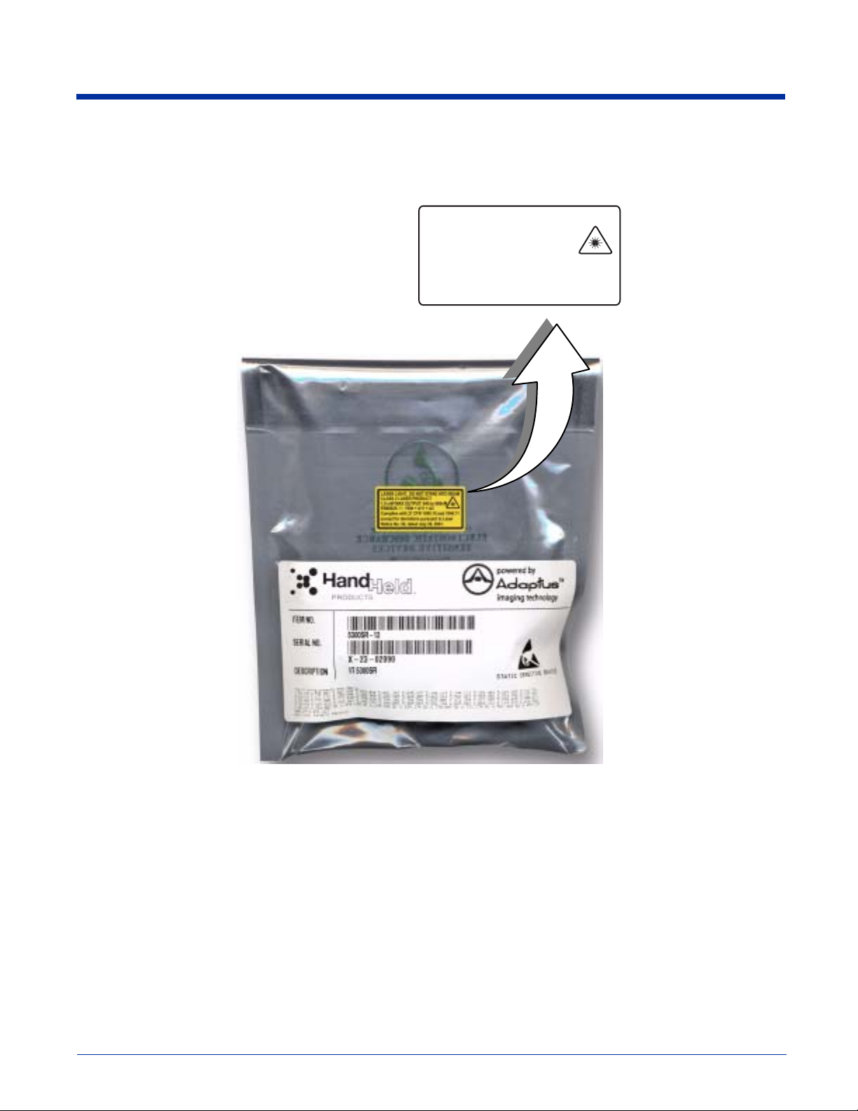
Laser Eye Safety Statement for IT4300 Series Engines
The IT4300 is intended for use in CDRH/IEC Class 2 devices.
/$6(5/,*+7'212767$5(,172%($0
&/$66/$6(5352'8&7
P:0$;287387WRQ0
(1$$
&RPSOLHVZLWK&)5DQG
H[FHSWIRUGHYLDWLRQVSXUVXDQWWR/DVHU
1RWLFH1RGDWHG-XO\
Note: It is the OEM manufacturer’s responsibility to comply with applicable regulation(s) in regard to standards for specific
equipment combinations.
Caution: Use of controls or adjustment or performance of procedures other than those specified herein may result in
hazardous radiation exposure.
Page 4

Page 5

Table of Contents
Chapter 1 - Introduction and Overview
Design Overview....................................................................................................................................1
User Layer........................................................................................................................................1
OEM API Layer............................................................................................................................... 1
Image Acquisition Layer.................................................................................................................. 1
Hardware Interface Layer ................................................................................................................1
Alphabetic Function List ........................................................................................................................2
AimIsOnICMedia ............................................................................................................................2
AimOffICMedia ..............................................................................................................................2
AimOnICMedia ..............................................................................................................................2
AllocatePhysicalScanSpaceICMedia .............................................................................................. 2
BindPhysicalMemoryToVirtualMemoryICMedia .......................................................................... 3
CaptureInitiatedICMedia ................................................................................................................3
DeinitializeImageLineDataProcessingICMedia ..............................................................................3
DeinitializeVsyncProcessingICMedia ............................................................................................ 3
DisableImageLineDataProcessingICMedia .................................................................................... 4
DisableVsyncInterruptICMedia ......................................................................................................4
EnableImageLineDataProcessingICMedia ..................................................................................... 4
EnableVsyncInterruptICMedia .......................................................................................................4
FreePhysicalScanSpaceICMedia ....................................................................................................5
GetFrequencyPerFrameOfLineDataCallbackICMedia ................................................................... 5
GetHardwareDllRevisionICMedia ..................................................................................................5
GetImagerPropertiesICMedia .........................................................................................................6
GetNumberOfValidRowsICMedia .................................................................................................6
GetRegisterSettingsForHHPExposureControlICMedia ..................................................................7
GetScanHeightICMedia .................................................................................................................. 7
GetScanWidthICMedia ...................................................................................................................7
IllumIsOnICMedia ..........................................................................................................................7
IllumOffICMedia ............................................................................................................................8
IllumOnICMedia .............................................................................................................................8
ImagerIsPoweredICMedia ..............................................................................................................8
ImagerPowerDownICMedia ...........................................................................................................8
ImagerPowerOffAndSuspendICMedia ........................................................................................... 8
ImagerPowerOnAndResumeICMedia ............................................................................................ 9
ImagerPowerUpICMedia ................................................................................................................9
InDownTimeICMedia .....................................................................................................................9
InitCaptureICMedia ......................................................................................................................10
InitializeImageLineDataProcessingICMedia ................................................................................ 10
InitializeVsyncProcessingICMedia ...............................................................................................10
ReadIIC_ICMedia .........................................................................................................................11
RegisterImageLineDataNotificationICMedia ............................................................................... 11
RegisterVsyncNotificationICMedia ..............................................................................................11
RequestSynchronizedPowerDownICMedia ..................................................................................11
ResetTransferHardwareICMedia .................................................................................................. 12
SynchronizedPowerDownICMedia ..............................................................................................12
UnBindPhysicalMemoryFromVirtualMemoryICMedia ...............................................................12
WaitForVsyncICMedia .................................................................................................................12
WaitMillisecondsICMedia ............................................................................................................13
WriteIIC_ICMedia ........................................................................................................................ 13
Chapter 2 - Customer Support
Technical Assistance ............................................................................................................................ 15
Online Technical Assistance..........................................................................................................15
IMAGETEAM™ 4X00 Series Hardware Interface Layer Specification User’s Guide i
Page 6

ii IMAGETEAM™ 4X00 Series Hardware Interface Layer Specification User’s Guide
Page 7

Introduction and Overview
This document is an overview of the structure of the IT4X00 Series OEM imaging software provided by Hand Held Products.
Detailed information that describes the Hand Held Products OEM Application Programming Interface (
User’s Guide
) is provided as a part of that imaging software.
Design Overview
The Hand Held Products OEM imaging software supports a number of different Hand Held Products imaging engines while
exposing the user to a common programming interface for all imagers supported. This approach provides Hand Held Products
with a simple way of adding support for new imaging hardware, while allowing user software to remain largely unchanged. In
support of this design approach, the software components implemented in the Hand Held Products OEM imaging software have
been organized in the following layered format:
User Layer
OEM API Layer
Image Acquisition Layer
Hardware Interface Layer
Of the four layers, Hand Held Products supplies the OEM API and Image Acquisition layers.
IMAGETEAM 4X00 SDK
User Layer
The User Layer can be the application that is written by a developer or end user that accesses the imaging system by using the
OEM API functions. The User Layer can alternatively be an abstraction layer provided by an OEM that allows the OEM to
customize the level of API functionality exposed to their end user. Either option has access to all the applicable OEM API
functions that access and control the imaging subsystem
OEM API Layer
The OEM API Software is supplied by Hand Held Products and is the primary interface to the imaging system. All members of
the OEM Image Engine Family are supplied with a Software Developers Kit to facilitate command and control of the image
engines. For Windows CE
Link Library. For non-Windows CE applications, the form of the OEM API Software is to be determined. Full explanation of the
OEM API is provided in the
®
applications, the OEM API Software functionality is provided in the form of a Windows Dynamic
IMAGETEAM 4X00 SDK User’s Guide
.
Image Acquisition Layer
The Image Acquisition Software layer is the software supplied by Hand Held Products that is responsible for imager auto
detection, initialization, state management, exposure control, and image acquisition. During application execution, this software
maintains the state and control of the imager, processes requests for images, and executes configuration and control requests.
For Windows CE applications, this layer is implemented in a stream device driver and is used by the OEM API layer. For nonWindows CE applications, the form of this layer and its interface to the OEM API layer is to be determined.
Hardware Interface Layer
The Hardware Interface Software is the hardware-specific software provided by the system developer and used by the Image
Acquisition Software to access the physical imaging hardware and run hardware-specific tasks on the system. This software is
called upon by Image Acquisition Software to handle physical control of the hardware, such as communication with the imager,
timing functionality, low level interrupt service routine control, DMA initialization and control, system specific memory control, and
illumination functionality. For Windows CE applications, it is expected that this layer will be provided in the form of a Windows
Dynamic Link Library that will be loaded by the Imaging device driver. For non-Windows CE applications, the form of this layer
and its interface to the Image Acquisition Software is to be determined.
IMAGETEAM™ 4X00 Series Hardware Interface Layer Specification 1
Page 8

Alphabetic Function List
The following is a list of functions that the ImagerHardware DLL must export to support the imaging device driver. The functions
described below are specific to the IC Media imager and the ICMedia product specification and should be reviewed for coherency
with this document.
AimIsOnICMedia
This function returns the state of the aimer.
BOOL AimIsOnICMedia(
void
)
Returns
Zero if OFF, non-zero if ON.
AimOffICMedia
This function turns off the aimer.
BOOL TurnAimerOffICMedia(
void
)
Returns
Zero on failure, non-zero on success
AimOnICMedia
This function turns on the aimer.
BOOL TurnAimerOnICMedia(
void
)
Returns
Zero on failure, non-zero on success.
AllocatePhysicalScanSpaceICMedia
This function reserves the physical memory for a single image. It does not matter to the driver how physical memory is handled
on the specific platform. When the "pseudo-handle" is passed to various functions, a specific block of physical memory is
referenced.
DWORD AllocatePhysicalScanSpaceICMedia(
void
)
Returns
DWORD - a "pseudo-handle" to physical memory on success. This "pseudo-handle" will be used to communicate a
specific physical buffer when other memory functions are called. This function returns zero on failure.
2 IMAGETEAM™ 4X00 Series Hardware Interface Layer Specification
Page 9

BindPhysicalMemoryToVirtualMemoryICMedia
This function binds the physical memory of an image, specified by "hPhysical," to a virtual memory location specified by
"pVirtual."
Note: It is possible that multiple calls to this function may be made with the same physical pseudo-handle, but a different virtual
address, i.e., binding multiple virtual addresses to the same physical space at the same time. This is normal.
DWORD BindPhysicalMemoryToVirtualMemoryICMedia(
DWORD hPhysical,
void *pVirtual
)
Passed Arguments Description
DWORD hPhysical A "pseudo-handle" to a reserved physical memory slot. This was the "pseudo-handle"
returned by AllocatePhysicalScanSpaceICMedia when the space was allocated.
void *pVirtual A pointer to a virtual address to be bound to the physical memory referenced by
hPhysical.
Returns
Zero on failure, non-zero on success.
CaptureInitiatedICMedia
In order to stay synchronized with the incoming images, the scan driver needs to know when each request to acquire a new image
has been successfully completed. A request for a new capture that is made before the front edge of the Vsync signal (an optional
function) should be carried out on the front edge of the next Vsync signal. CaptureInitiatedICMedia is called after the front edge
of Vsync to determine if that has happened.
DWORD CaptureInitiatedICMedia(
void
)
Returns
Zero indicates that on the last front edge of Vsync a new capture request was not carried out. This will occur either
because the requet was never made, or because the request was made but was unsuccessful.
Non-zero indicates that a new capture request was carried out on the last front edge of Vsync.
DeinitializeImageLineDataProcessingICMedia
This function is used to destroy, or undo any software or hardware configurations that are associated with the calling of the image
data line processing.
DWORD DeinitializeImageLineDataProcessingICMedia(
void
)
Returns
Zero on failure, non-zero on success.
DeinitializeVsyncProcessingICMedia
This function disables the system from responding to the Vsync pulse from the imager. This involves undoing the setup
performed via the InitializeVsyncProcessingICMedia (see page 10), function.
DWORD DeinitializeVsyncProcessingICMedia(
void
)
IMAGETEAM™ 4X00 Series Hardware Interface Layer Specification 3
Page 10

Returns
Zero on failure, non-zero on success.
DisableImageLineDataProcessingICMedia
This function disables the calling of the ImageLineDataCallback function registered with
RegisterImageLineDataNotificationICMedia (see page 1-11).
DWORD DisableImageLineDataInterruptICMedia(
void
)
Returns
Zero on failure, non-zero on success.
DisableVsyncInterruptICMedia
This function disables the calling of the Vsync call-back function, registered with RegisterVsyncNotificationICMedia (see page
11), on receiving the front edge of a Vsync.
DWORD DisableVsyncInterruptICMedia(
void
)
Returns
Zero on failure, non-zero on success.
EnableImageLineDataProcessingICMedia
This function enables the calling of the call-back function, registered via RegisterImageLineDataNotificationICMedia (see page
11), according to the criteria set forth by the hardware system, and initialized via InitializeImageLineDataProcessingICMedia (see
page 10). It should be noted that the callback should only be called when image data is currently being captured from the image
engine.
DWORD EnableImageLineDataInterruptICMedia(
void
)
Returns
Zero on failure, non-zero on success.
EnableVsyncInterruptICMedia
This function enables the calling of the Vsync call-back function, registered with RegisterVsyncNotificationICMedia (see page
11), on receiving the front edge of a Vsync.
DWORD EnableVsyncInterruptICMedia(
void
)
Returns
Zero on failure, non-zero on success.
4 IMAGETEAM™ 4X00 Series Hardware Interface Layer Specification
Page 11

FreePhysicalScanSpaceICMedia
This function frees the physical memory for a single image.
DWORD FreePhysicalScanSpaceICMedia(
DWORD hImage
)
Passed Arguments Description
DWORD hImage A "pseudo-handle" to a reserved physical memory slot. This was the value returned by
AllocatePhysicalScanSpaceICMedia when the space was allocated.
Returns
DWORD - This function returns non-zero on success, zero on failure.
GetFrequencyPerFrameOfLineDataCallbackICMedia
This function returns the number of calls made to the image line data callback function during each frame. When using an
operating system such as Windows CE, it may be difficult to tell consistently how many callbacks may be made per frame. In
that case, make a low estimate. Therefore, if on a given system the callback may be called from 28-33 times, a safe number
would be 27.
DWORD GetFrequencyPerFrameOfLineDataCallbackICMedia(
void
)
Returns
A number 'N' that completes this statement, "the line processing occurs at least 'N' times per frame."
GetHardwareDllRevisionICMedia
This function returns a revision number of the hardware DLL. The functions included with any given revision of the hardware
DLL are determined by this number. This guarantees that if the Image Acquisition Layer driver software is updated, but a
hardware DLL has not been updated, the software will be backward compatible. This document represents what should be
included in revision 1 of the hardware DLL.
Note: This function can be used as a general hardware layer initialization function since it is only called by the scan driver one
time, and it does not have the limitations of a base DLL initialization (for example, it can’t call Win32 API functions).
DWORD GetHardwareDllRevisionICMedia(
void
)
Returns
Revision number of the hardware DLL.
IMAGETEAM™ 4X00 Series Hardware Interface Layer Specification 5
Page 12

GetImagerPropertiesICMedia
This function requests the properties of the imager currently interfacing to the hardware layer.
BOOL GetImagerPropertiesICMedia(
const DWORD * pBuffIn,
DWORD * pBuffOut,
DWORD dwLen
)
Passed Arguments Description
pBuffIn Pointer to a buffer of DWORDs that are TAGs to the properties the scan driver is
requesting.
pBuffOut Pointer to output buffer that has corresponding values and order to TAGs in pBuffin.
dwLen Length of both pBuffin and pBuffOut.
Tags:
typedef enum {
IP_SIZE,
IP_ENGINE_ID,
IP_NUM_ROWS,
IP_NUM_COLS,
IP_BITS_PER_PIXEL,
IP_ROTATION,
IP_AIMER_X_OFFSET,
IP_AIMER_Y_OFFSET,
IP_YDEPTH
} HHPScanDriverImagerProperties_t;
Returns
TRUE if successful, FALSE otherwise.
GetNumberOfValidRowsICMedia
This function is called in the middle of image captures to find out how many image rows of data have been transferred completely
in the incoming image at a given time.
DWORD GetNumberOfValidRowsICMedia()
Returns
DWORD - The number of valid image rows of data.
6 IMAGETEAM™ 4X00 Series Hardware Interface Layer Specification
Page 13

GetRegisterSettingsForHHPExposureControlICMedia
This function is used for the hardware DLL to give the driver access to the register settings needed for its hardware platform.
The structure below represents the array data type the GetRegisterSettingsForHHPExposureControlICMedia function returns to
the driver via the ppRegisterEntries pointer:
typedef struct {
unsigned char nRegister;
unsigned char nValue;
} ICMediaRegisterEntry_t;
DWORDGetRegisterSettingsForHHPExposureControlICMedia(
ICMediaRegisterEntry_t **ppRegisterEntries
)
Passed Arguments Description
ICMediaRegisterEntry_t **ppRegisterEntries
A pointer to a location where a pointer to the register settings can be set. The
ICMediaRegisterEntry_t is defined above. The table itself is an array of these
structures having a register location, and the value it is to be set to in each entry.
Returns
DWORD - The number of entries in the table returned to the driver.
GetScanHeightICMedia
This function returns the number of rows in the image.
DWORD GetScanHeight(
void
)
Returns
Number of rows or zero on failure.
GetScanWidthICMedia
This function returns the number of columns in the image.
DWORD GetScanWidth(
void
)
Returns
Number of columns or zero on failure.
IllumIsOnICMedia
This function returns the state of the illumination LEDs.
BOOL IllumIsOnICMedia(
void
)
Returns
Zero if OFF, non-zero if ON.
IMAGETEAM™ 4X00 Series Hardware Interface Layer Specification 7
Page 14

IllumOffICMedia
This function turns off the illumination LEDs.
BOOL TurnLEDsOffICMedia(
void
)
Returns
Zero on failure, non-zero on success.
IllumOnICMedia
This function turns on the illumination LEDs.
BOOL TurnLEDsOnICMedia(
void
)
Returns
Zero on failure, non-zero on success.
ImagerIsPoweredICMedia
This function indicates whether or not the image engine is currently in powerdown mode.
BOOL ImagerIsPoweredICMedia(
void
)
Returns
Zero if the engine is currently in powerdown mode, non-zero if it is not.
ImagerPowerDownICMedia
This function puts the image engine into powerdown mode via a power enable signal.
BOOL ImagerPowerDownICMedia(
void
)
Returns
Zero if successful, non-zero otherwise.
ImagerPowerOffAndSuspendICMedia
This function controls a physical switch to cycle power off the imager. This is typically implemented for Win CE suspend/resume.
DWORD ImagerPowerOffAndSuspendICMedia(
DWORD
)
Passed Arguments Description
0 Normal case. Win 32 API functions are still allowed.
1 Suspend/Resume. (For example, in Win CE this implies that it is not safe to call Win32
or user layer functions.)
8 IMAGETEAM™ 4X00 Series Hardware Interface Layer Specification
Page 15

Returns
TRUE if successful, FALSE otherwise.
ImagerPowerOnAndResumeICMedia
This function controls a physical switch to cycle power on the imager. This is typically implemented for Win CE suspend/resume.
DWORD ImagerPowerOnAndSuspendICMedia(
DWORD
)
Passed Arguments Description
0 Normal case. Win 32 API functions are still allowed.
1 Suspend/Resume. (For example, in Win CE this implies that it is not safe to call Win32
or user layer functions.)
2 Resume, but don't power on. To be powered on during next image I/0 event.
Returns
TRUE if successful, FALSE otherwise.
ImagerPowerUpICMedia
This function takes the image engine out of powerdown mode via a power enable signal.
BOOL ImagerPowerUpICMedia(
void
)
Returns
Zero if successful, non-zero otherwise.
InDownTimeICMedia
This function tells whether you are in the appropriate area of the frame to successfully write registers to have them take effect
for the next image. "Down Time" represents the time between frames. For the IC Media 105A imager, this is the time when the
Vsync state represents that no valid pixel data is available.
BOOL InDownTimeICMedia(
int
)
Returns
Zero if successful, non-zero if currently in the "down time" of the frame.
IMAGETEAM™ 4X00 Series Hardware Interface Layer Specification 9
Page 16

InitCaptureICMedia
This function indicates that a transfer will begin on the next Vsync pulse, and the image data will go into the physical memory
location referenced by "hPhysical." This function can be called at any time during a frame, and the driver relies on the hardware
DLL and associated functionality to synchronize to the next Vsync to begin a frame. The Vsync is the border. Anything that
comes in before the front edge of a Vsync will initiate a transfer on the next Vsync. Anything that comes in after that edge of
Vsync will wait for the next Vsync.
Note: The scan driver then assumes that because the Vsync IST runs after this front edge of Vsync, that any calls to
InitCaptureICMedia that are made during the Vsync IST will wait until the front edge of the next Vsync to be initiated
DWORD InitCaptureICMedia(
DWORD hPhysical
)
Passed Arguments Description
DWORD hPhysical A "pseudo-handle" to a reserved physical memory slot. This is the "pseudo-handle"
returned by AllocatePhysicalScanSpaceICMedia when the space was allocated.
Returns
Zero on failure.
1 - capture request was initiated, but it happened just after the front edge of Vsync (i.e., in down time), and therefore will
only take effect on the next front edge of Vsync.
2 - capture request will take effect on next front edge of Vsync.
InitializeImageLineDataProcessingICMedia
This function is used to set up any necessary hardware and or software associated with generating the callback to the data line
processing functionality in the scan driver. This should not enable the calling of this callback. It should only initialize it. To enable
or disable, use the EnableImageLineDataProcessingICMedia (see page 4), or the
DisableImageLineDataProcessingICMedia (see page 4) function.
DWORD InitializeImageLineDataProcessingICMedia(
void
)
Returns
Zero on failure, non-zero on success.
InitializeVsyncProcessingICMedia
This function configures the hardware and software of the system to respond to the front edge of the Vsync, and put in place the
mechanisms that perform the call of the callback upon the receipt of that edge. The callback functionality is only initialized int his
function, not enabled. (see EnableVsyncProcessingICMedia and DisableVsyncProcessingICMedia).
DWORD InitializeVsyncProcessingICMedia(
void
)
Returns
Zero on failure, non-zero on success.
10 IMAGETEAM™ 4X00 Series Hardware Interface Layer Specification
Page 17

ReadIIC_ICMedia
This function uses the i2c interface protocol to read data from 'ucSubaddress' register location and places it at the location
specified by 'pucBuffer'.
unsigned int ReadIIC_ICMedia(
unsigned char ucSubaddress,
unsigned char *pucBuffer
)
Passed Arguments Description
unsigned char ucSubaddress The register location where the data will be read from.
unsigned char *pucBuffer A pointer to the location where the data from the imager will be stored.
Returns
Non-zero if data is successfully read. Zero if there was an error.
RegisterImageLineDataNotificationICMedia
This function is called during initialization of the imager to register a function to be called at various points during the image
acquisition process. This function will most likely be called as the result of a hardware generated line interrupt, an IST generated
from that interrupt, or at different times throughout an image capture based on an internal software scheduler.
DWORD RegisterImageLineDataNotificationICMedia(
void (*fImgDataNotif)(void)
)
Passed Arguments Description
void (*fImgDataNotif)(void) Function pointer to a function that receives no arguments, and returns nothing.
Returns
Zero on failure, non-zero on success.
RegisterVsyncNotificationICMedia
This function is called during initialization of the imager to register a function to be called after the Vsync interrupt. This function
could be called as part of an ISR handler or, as in WinCE applications, this registered function will most likely be called from an
IST.
DWORD RegisterVsyncNotificationICMedia(
void (*fVsyncNotif)(void)
)
Passed Arguments Description
void (*fVsyncNotif)(void) Function pointer to a function that receives no arguments, and returns nothing.
Returns
Zero on failure, non-zero on success.
RequestSynchronizedPowerDownICMedia
This function requests that the imager be put in power down mode upon receiving the next front edge of Vsync. The IC Media
imager freezes when it goes into power down mode, and the goal is to have the imager in the “between frames” state (i.e., in
down time) when this request is made. The difference between this function and the SynchronizedPowerDownICMedia function
is that this function does not wait until the next Vsync to check to see if the imager has successfully been put into power down
mode. The area of the scan driver that uses this function performs that check separately.
void RequestSynchronizedPowerDownICMedia(
void
)
IMAGETEAM™ 4X00 Series Hardware Interface Layer Specification 11
Page 18

Returns
None.
ResetTransferHardwareICMedia
This function stops a transfer that is either ready to run, or currently running. It also resets the system making it ready for the
next call to InitCaptureICMedia.
void ResetTransferHardwareICMedia(
void
)
Returns
None.
SynchronizedPowerDownICMedia
This function puts the imager in power down mode upon receiving the next front edge of Vsync. The IC Media imager freezes
when it goes into power down mode, so one of the checks after the power down is to make sure the Vsync is in the "between
frames" state (in down time), since that’s where the IC Media camera should be frozen.
BOOL SynchronizedPowerDownICMedia()
Returns
Non-zero if successfully powered down in the down time.
UnBindPhysicalMemoryFromVirtualMemoryICMedia
This function unbinds the physical memory of an image, specified by "hPhysical," from the virtual memory location specified by
"pVirtual." This does not, however, free any memory. The "pVirtual" pointer should still be a valid pointer pointing to RESERVED
but not COMMITTED memory, and the physical memory should still be available for future bindings.
DWORD UnBindPhysicalMemoryFromVirtualMemoryICMedia(
DWORD hPhysical,
void *pVirtual
)
Passed Arguments Description
DWORD hPhysical A "pseudo-handle" to a reserved physical memory slot. This was the "pseudo-handle"
returned by AllocatePhysicalScanSpaceICMedia when the space was allocated.
void *pVirtual A pointer to a virtual address.
Returns
DWORD - This function returns non-zero on success, zero on failure.
WaitForVsyncICMedia
This function waits until the imager sees the front edge of the Vsync, then it returns. Since many systems involve threads going
to sleep waiting for this event to occur, a safety check on the way out of this function is to see if the Vsync reflects the camera
being "between frames" (down time).
BOOL WaitForVsyncICMedia()
Returns
Non-zero on successful synchronization to the Vsync before returning.
12 IMAGETEAM™ 4X00 Series Hardware Interface Layer Specification
Page 19

WaitMillisecondsICMedia
This function waits the number of milliseconds indicated before returning.
void WaitMillisecondsICMedia(
DWORD nTime
)
Passed Arguments Description
NTime The number of milliseconds to delay.
Returns
None.
WriteIIC_ICMedia
This function uses the i2c interface protocol to write the 'ucBuffer' data to the imager at the 'ucSubaddress' location.
DWORD WriteIIC_ICMedia(
unsigned char ucSubaddress,
const unsigned char *pucBuffer
)
Passed Arguments Description
unsigned char ucSubaddress The 8 bit address where data will start being written to.
unsigned char *pucBuffer A pointer to the byte of data that will be written to the "subaddress."
Returns
Non-zero if data is successfully transferred. Zero on error.
IMAGETEAM™ 4X00 Series Hardware Interface Layer Specification 13
Page 20

Programming Notes
1. It is essential that callbacks for Vsync processing and Image Line Data processing not run at the same time, for example,
with 2 separate threads. It is essential that checks are made in the Hardware Interface DLL to ensure that a call to one
callback is complete before a second call to that callback, or a call to the other callback is made. To avoid this, use ISRs
that do not allow nesting. Or, if using ISTs in the Windows CE model, use the same thread to process both callbacks.
2. It is assumed that an image transfer is initiated on the front edge of Vsync. InitCaptureICMedia (see page 10) can be
called at any time during the frame, and the hardware DLL must synchronize it with the hardware. Returning a 1 or 2 from
InitCaptureICMedia is not mandatory. If a specific hardware system allows for initiation of an image transfer after the front
edge of Vsync, a 2 may be returned when InitCaptureICMedia is called because it takes effect for the next frame. But it is
imperative that calls made to InitCaptureICMedia from the Vsync callback only take effect on the next Vsync front edge.
3. If running an Operating System on the target platform, such as Windows CE, processing of the Vsync and Image Data Line
callbacks must be high priority to ensure proper timing.
4. There are times when the Vsync callback function will have to wait for longer than a single frame time for an event,
resulting in a second Vsync front edge being seen. If, upon returning from the Vsync callback function, another Vsync front
edge has passed,
do not
call the callback again. Wait for the next one.
14 IMAGETEAM™ 4X00 Series Hardware Interface Layer Specification
Page 21

Customer Support
Technical Assistance
If you need assistance using the IT4X00 Series OEM imaging software, please call your Distributor or the nearest Hand Held
Products technical support office:
North America/Canada:
Telephone: (800) 782-4263, option 4 (8 a.m. to 6 p.m. EST)
Fax number: (315) 685-4960
E-mail: natechsupport@handheld.com
Europe, Middle East, and Africa:
TelephoneEuropean Ofc: Int+31 (0) 40 79 99 393
U.K. Ofc: Int+44 1925 240055
E-mail: eutechsupport@handheld.com
Asia Pacific:
Telephone: Int+852-3188-3485
E-mail: aptechsupport@handheld.com
America Latina:
Teléfono: (704) 998-3998, opción 8
E-mail: latechsupport@handheld.com
or
2511-3050
Online Technical Assistance
You can also access technical assistance online at www.handheld.com.
IMAGETEAM™ 4X00 Series Hardware Interface Layer Specification 15
Page 22

16 IMAGETEAM™ 4X00 Series Hardware Interface Layer Specification
Page 23

Page 24

Hand Held Products, Inc.
700 Visions Drive
P.O. Box 208
Skaneateles Falls, NY 13153-0208
™
4X00HWIntfc-UG Rev B
(6/05)
 Loading...