

HandHeld 4800P User Manual

4800p
™
User’s Guide
4800p 2D Imager

Disclaimer
Hand Held Products, Inc. (“Hand Held Products”) reserves the right to make
changes in specifications and other information contained in this document
without prior notice, and the reader should in all cases consult Hand Held
Products to determine whether any such changes have been made. The
information in this publication does not represent a commitment on the part of
Hand Held Products.
Hand Held Products shall not be liable for technical or editorial errors or
omissions contained herein; nor for incidental or consequential damages
resulting from the furnishing, performance, or use of this material.
This document contains proprietary information that is protected by copyright. All
rights are reserved. No part of this document may be photocopied, reproduced,
or translated into another language without the prior written consent of Hand
Held Products.
©2007 Hand Held Products, Inc. All rights reserved.
Web Address: www.handheld.com
®
Microsoft
Corporation in the United States and/or other countries.
Macintosh
other countries.
Other product names or marks mentioned in this document may be trademarks
or registered trademarks of other companies and are the property of their
respective owners.
Windows® is either a registered trademark or trademarks of Microsoft
®
is a trademark of Apple Computer, Inc., registered in the U.S. and
FCC Compliance Statement
This device complies with part 15 of the FCC Rules. Operation is subject to the
following two conditions: (1) this device may not cause harmful interference, and
(2) this device must accept any interference received, including interference that
may cause undesired operation.
FCC Class B Compliance Statement
This equipment has been tested and found to comply with the limits for a Class
B digital device pursuant to part 15 of the FCC Rules. These limits are designed
to provide reasonable protection against harmful interference in a residential
installation. This equipment generates, uses, and can radiate radio frequency
energy and, if not installed and used in accordance with the instructions, may
cause harmful interference to radio communications. However, there is no
guarantee that interference will not occur in a particular installation. If this
equipment does cause harmful interference to radio or television reception,
which can be determined by turning the equipment off and on, the user is
encouraged to try to correct the interference by one or more of the following
measures:
• Reorient or relocate the receiving antenna.

• Increase the separation between the equipment and receiver.
• Connect the equipment into an outlet on a circuit different from that to which
the receiver is connected.
• Consult the dealer or an experienced radio or television technician for help.
Caution: Any changes or modifications made to this equipment not
expressly approved by Hand Held Products, Inc. may void the
FCC authorization to operate this equipment.
Note: To maintain compliance with FCC Rules and Regulations, cables
connected to this device must be Hand Held Products approved shielded
cables, in which the cable shield wire(s) have been grounded (tied) to the
connector shell. Installation of the included ferrite is required to meet
emission requirements.
Canadian Notice
This equipment does not exceed the Class B limits for radio noise emissions as
described in the Radio Interference Regulations of the Canadian Department of
Communications.
Le present appareil numerique n’emet pas de bruits radioelectriques depassant
les limites applicables aux appareils numeriques de la classe B prescrites dans
le Reglement sur le brouillage radioelectrique edicte par le ministere des
Communications du Canada.
Note: To maintain compliance with FCC Rules and Regulations, cables
connected to this device must be shielded cables, in which the cable
shield wire(s) have been grounded (tied) to the connector shell.
Installation of the included ferrite is required to meet emission
requirements.
CE Mark
The CE mark on the product indicates that the system has been
tested to and conforms with the provisions noted within the 2004/108/
EC Electromagnetic Compatibility Directive and the 2006/95/EC Low
Voltage Directive.
Complies with:
EN55022:2006 (for ITE emissions)
EN55024:1998 (for ITE immunity)
EN61000-3-2:2000
EN61000-3-3:1995
For further information please contact:
Hand Held Products
Nijverheidsweg 9-13
5627 BT Eindhoven
The Netherlands

Hand Held Products, Inc. shall not be liable for use of our product with equipment
(i.e., power supplies, personal computers, etc.) that is not CE marked and does
not comply with the Low Voltage Directive.
Note: To maintain compliance with FCC Rules and Regulations, cables
connected to this device must be shielded cables, in which the cable
shield wire(s) have been grounded (tied) to the connector shell.
Installation of the included ferrite is required to meet emission
requirements.
UL and cUL Statement
UL and cUL listed: UL60950-1 and CSA C22.2 No.60950-1.
LED Safety Statement
This device has been tested in accordance with EN60825-1:1993+A1+A2 LED
safety, and has been certified as a Class 1 LED device.
GS Mark
This product has been issued a GS certificate.
Patents
Please refer to the product packaging for a list of patents.
Waste Electrical and Electronic Equipment Information
For European Community Users
Note: Hand Held Products complies with Directive 2002/96/EC OF THE
EUROPEAN PARLIAMENT AND OF THE COUNCIL of 27 January 2003
on waste electrical and electronic equipment (WEEE).
This product has required the extraction and use of natural resources for its
production. It may contain hazardous substances that could impact health and
the environment, if not properly disposed.

In order to avoid the dissemination of those substances in our environment and
to diminish the pressure on the natural resources, we encourage you to use the
appropriate take-back systems for product disposal. Those systems will reuse or
recycle most of the materials of the product you are disposing in a sound way.
The crossed out wheeled bin symbol informs you that the product should
not be disposed of along with municipal waste and invites you to use the
appropriate separate take-back systems for product disposal.
If you need more information on the collection, reuse, and recycling systems,
please contact your local or regional waste administration.
You may also contact your supplier for more information on the environmental
performances of this product.


Table of Contents
Chapter 1 - Getting Started
About This Manual ............................................................... 1-1
Unpacking the Imager........................................................... 1-1
Imager Models ...................................................................... 1-2
Imager Identification ............................................................ 1-2
Connecting the Imager with USB ........................................ 1-3
Programming the Interface - Plug and Play.......................... 1-4
USB PC or Macintosh
USB HID........................................................................ 1-4
USB COM Port Emulation............................................. 1-5
Reading Techniques.............................................................. 1-5
4800p Stand .......................................................................... 1-6
Chapter 2 - Terminal Interfaces
Terminal ID .......................................................................... 2-1
Supported Terminals............................................................. 2-2
Keyboard Country ................................................................ 2-3
Keyboard Style ..................................................................... 2-5
Keyboard Modifiers ............................................................. 2-7
®
Keyboard ................................. 1-4
Chapter 3 - Output
Good Read Indicators ........................................................... 3-1
Beeper – Good Read ...................................................... 3-1
Beeper Volume – Good Read ........................................ 3-1
Beeper Pitch – Good Read ............................................. 3-2
Beeper Duration – Good Read ....................................... 3-2
Number of Beeps – Good Read ..................................... 3-2
Good Read Delay.................................................................. 3-3
User-Specified Good Read Delay......................................... 3-3
Reread Delay ........................................................................ 3-4
User-Specified Reread Delay ............................................... 3-4
LED Power Level ................................................................. 3-5
Centering............................................................................... 3-5
i

Decode Search Mode............................................................ 3-7
Output Sequence Overview .................................................. 3-7
Output Sequence Editor ............................................... 3-10
Require Output Sequence............................................. 3-10
Print Weight........................................................................ 3-11
Video Reverse..................................................................... 3-11
Working Orientation........................................................... 3-12
Chapter 4 - Data Editing
Prefix/Suffix Overview......................................................... 4-1
To Add a Prefix or Suffix: ............................................. 4-2
To Clear One or All Prefixes or Suffixes:...................... 4-3
To Add a Carriage Return Suffix to all Symbologies .... 4-3
Prefix Selections............................................................. 4-4
Suffix Selections ............................................................ 4-4
Function Code Transmit................................................. 4-4
Intercharacter, Interfunction, and Intermessage Delays ....... 4-5
Intercharacter Delay ....................................................... 4-5
User Specified Intercharacter Delay .............................. 4-6
Interfunction Delay ........................................................ 4-6
Intermessage Delay ........................................................ 4-7
Chapter 5 - Data Formatting
Data Format Editor Introduction .......................................... 5-1
To Add a Data Format.................................................... 5-1
Other Programming Selections ...................................... 5-2
Data Format Editor Commands ..................................... 5-2
Data Format Editor......................................................... 5-5
Data Formatter ............................................................... 5-5
Alternate Data Formats .................................................. 5-6
ii

Chapter 6 - Symbologies
Message Length Description................................................. 6-2
Codabar Start/Stop Characters....................................... 6-3
Codabar Check Character............................................... 6-3
Codabar Concatenation .................................................. 6-4
Codabar Message Length ............................................... 6-5
Code 39 Start/Stop Characters ....................................... 6-6
Code 39 Check Character............................................... 6-6
Code 39 Message Length ............................................... 6-7
Code 39 Append............................................................. 6-8
Code 32 Pharmaceutical (PARAF) ................................ 6-8
Full ASCII ...................................................................... 6-9
Code 39 Code Page ...................................................... 6-10
Check Digit................................................................... 6-10
Interleaved 2 of 5 Message Length .............................. 6-11
Code 93 Message Length ............................................. 6-12
Code 93 Code Page ...................................................... 6-12
Straight 2 of 5 Industrial Message Length ................... 6-13
Straight 2 of 5 IATA Message Length ......................... 6-14
Matrix 2 of 5 Message Length ..................................... 6-15
Check Digits Required ................................................. 6-16
Code 11 Message Length ............................................. 6-16
ISBT 128 Concatenation .............................................. 6-17
Code 128 Message Length ........................................... 6-18
Code 128 Code Page .................................................... 6-18
Telepen Output ............................................................. 6-19
Telepen Message Length.............................................. 6-19
UPC-A Check Digit...................................................... 6-20
UPC-A Number System ............................................... 6-20
UPC-A Addenda........................................................... 6-21
UPC-A Addenda Required........................................... 6-21
UPC-A Addenda Separator .......................................... 6-21
UPC-E0 ........................................................................ 6-22
UPC-E0 Expand ........................................................... 6-22
UPC-E0 Addenda Required ......................................... 6-23
UPC-E0 Addenda Separator......................................... 6-23
iii

UPC-E0 Check Digit.................................................... 6-23
UPC-E0 Number System ............................................. 6-24
UPC-E0 Addenda......................................................... 6-24
EAN/JAN-13 Check Digit ........................................... 6-25
EAN/JAN-13 Addenda ................................................ 6-26
EAN/JAN-13 Addenda Required................................. 6-26
EAN/JAN-13 Addenda Separator ................................ 6-26
ISBN Translate............................................................. 6-27
EAN/JAN-8 Check Digit ............................................. 6-27
EAN/JAN-8 Addenda .................................................. 6-28
EAN/JAN-8 Addenda Required................................... 6-28
EAN/JAN-8 Addenda Separator.................................. 6-28
MSI Check Character................................................... 6-29
MSI Message Length ................................................... 6-30
Plessey Message Length .............................................. 6-30
RSS Expanded Message Length .................................. 6-32
PosiCode Message Length ........................................... 6-33
Codablock F Message Length...................................... 6-34
Code 16K Message Length .......................................... 6-35
Code 49 Message Length ............................................. 6-36
PDF417 Message Length ............................................. 6-37
MicroPDF417 Message Length ................................... 6-38
UPC/EAN Version ....................................................... 6-39
EAN•UCC Composite Code Message Length............. 6-39
4-CB (4-State Customer Bar Code) ............................. 6-41
ID-tag (UPU 4-State) ................................................... 6-41
Postnet.......................................................................... 6-41
Planet Code .................................................................. 6-42
British Post................................................................... 6-43
Canadian Post............................................................... 6-43
Kix (Netherlands) Post................................................. 6-43
Australian Post ............................................................. 6-44
Australian Post Interpretation ...................................... 6-44
Japanese Post................................................................ 6-44
China Post Message Length ......................................... 6-45
Korea Post Message Length......................................... 6-46
QR Code Message Length ........................................... 6-47
iv

Data Matrix Message Length ....................................... 6-48
MaxiCode Message Length..........................................6-49
Aztec Code Message Length........................................ 6-50
Aztec Runes.................................................................. 6-50
Chapter 7 - Imaging Commands
Image Snap - IMGSNP ......................................................... 7-1
IMGSNP Modifiers ........................................................ 7-1
Image Ship - IMGSHP.......................................................... 7-2
IMGSHP Modifiers ........................................................ 7-3
Image Size Compatibility............................................... 7-6
Intelligent Signature Capture - IMGBOX............................. 7-7
IMGBOX Modifiers ....................................................... 7-7
Chapter 8 - OCR Programming
OCR ...................................................................................... 8-1
OCR Templates..................................................................... 8-3
Creating an OCR Template ............................................ 8-3
Stringing Together Multiple Formats
(Creating “Or” Statements) ............................................ 8-6
OCR User-Defined Variables ............................................... 8-6
Reading Multi-Row OCR............................................... 8-7
OCR Check Character........................................................... 8-8
OCR Modulo 10 Check Character ................................. 8-8
OCR Modulo 36 Check Character ................................. 8-9
OCR User-Defined Check Character.................................... 8-9
Weighting Options ....................................................... 8-10
OCR ISBN Application Example ....................................... 8-12
OCR Template Codes ......................................................... 8-13
Chapter 9 - Interface Keys
Keyboard Function Relationships......................................... 9-1
Supported Interface Keys...................................................... 9-3
v

Chapter 10 - Utilities
To Add a Test Code I.D. Prefix to All Symbologies.......... 10-1
Show Decoder Revision ..................................................... 10-1
Show Engine Revision........................................................ 10-1
Show Scan Driver Revision................................................ 10-2
Show Software Revision..................................................... 10-2
Show Data Format .............................................................. 10-2
Resetting the Standard Product Defaults ............................ 10-2
Test Menu ........................................................................... 10-3
2D PQA (Print Quality Assessment) .................................. 10-3
2D PQA Reporting....................................................... 10-3
™
Visual Xpress
Introduction .............................................. 10-4
Installing Visual Xpress from the Web........................ 10-5
Chapter 11 - Serial Programming Commands
Conventions ........................................................................ 11-1
Menu Command Syntax ..................................................... 11-1
Query Commands......................................................... 11-2
Concatenation of Multiple Commands ........................ 11-2
Responses..................................................................... 11-2
Examples of Query Commands ................................... 11-3
Resetting the Standard Product Defaults ............................ 11-4
Menu Commands................................................................ 11-5
Chapter 12 - Product Specifications
4800p Specifications........................................................... 12-1
Connector Pinouts ........................................................ 12-2
Chapter 13 - Maintenance
Repairs ................................................................................ 13-1
Maintenance........................................................................ 13-1
Cleaning the Device ..................................................... 13-1
Inspecting Cords and Connectors................................. 13-1
Replacing the Interface Cable ...................................... 13-2
vi

Troubleshooting .................................................................. 13-2
Chapter 14 - Customer Support
Technical Assistance........................................................... 14-1
Online Technical Assistance ........................................ 14-2
For Further Information................................................ 14-2
Product Service and Repair................................................. 14-2
Online Product Service and Repair Assistance ............ 14-3
Limited Warranty................................................................ 14-3
Appendix A
Symbology Chart ................................................................. A-1
ASCII Conversion Chart (Code Page 1252)........................ A-4
Code Page Mapping of Printed Bar Codes .......................... A-6
vii

viii

1
Getting Started
About This Manual
This User’s Guide provides installation and programming instructions for the
4000 Series imagers. Product specifications, dimensions, warranty, and
customer support information are also included.
Hand Held Products bar code imagers are factory programmed for the most
common terminal and communications settings. If you need to change these
settings, programming is accomplished by scanning the bar codes in this guide.
An asterisk (*) next to an option indicates the default setting.
Unpacking the Imager
After you open the shipping carton, take the following steps:
• Check for damage during shipment. Report damage immediately to the
carrier who delivered the carton.
• Make sure the items in the carton match your order.
• Save the shipping container for later storage or shipping.
4800p 2D Imager User’s Guide 1 - 1

Imager Models
Item Number,
Serial Number
and Revision
Information
location
Compliance
Label location
The chart below lists the interfaces that can be used with your imager.
Models Primary
4800pSF151CE USB keyboard, USB COM port
emulation
4800pSF151C0F00E
USB kit
Imager Identification
1 - 2 4800p 2D Imager User’s Guide
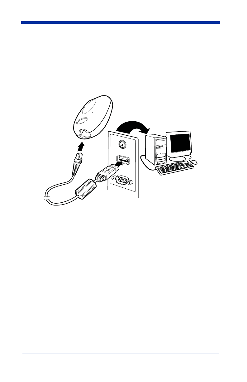
Connecting the Imager with USB
Note: See "Imager Models" on page 1-2 to determine which interfaces apply to
your imager.
An imager can be connected to the USB port of a computer.
1. Connect the appropriate interface cable to the imager first, then to the computer.
2. Program the imager for a USB interface using the Plug and Play bar codes
beginning on page 1-4.
3. The imager beeps.
4. Verify the imager operation by scanning a bar code from the Sample
Symbols in the back of this manual.
For additional USB programming and technical information, refer to Hand Held
Products “USB Application Note,” available at www.handheld.com.
4800p 2D Imager User’s Guide 1 - 3

Programming the Interface - Plug and Play
USB Keyboard (PC)
USB Keyboard (Mac)
USB Japanese Keyboard (PC)
USB HID Bar Code Imager
Plug and Play bar codes provide instant imager set up for commonly used
interfaces.
Note: After you scan one of the codes, power cycle the host terminal to have the
interface in effect.
Note: See "Imager Models" on page 1-2 to determine which interfaces apply to
your imager.
USB PC or Macintosh® Keyboard
Scan one of the following codes to program the imager for USB PC Keyboard or
USB Macintosh Keyboard. Scanning these codes adds a CR and selects the
terminal ID (USB PC Keyboard - 124, USB Macintosh Keyboard - 125, USB
Japanese Keyboard - 134).
USB HID
Scan the following code to program the imager for USB HID bar code imagers.
Scanning this code changes the terminal ID to 131.
1 - 4 4800p 2D Imager User’s Guide

USB COM Port Emulation
USB COM Port Emulation
On
* Off
On
* Off
Scan the following code to program the imager to emulate a regular RS-232based COM port. If you are using a Microsoft® Windows® PC, you will need to
download a driver from the Hand Held Products website (www.handheld.com
The driver will use the next available COM port number. Apple® Macintosh
computers recognize the imager as a USB CDC class device and automatically
use a class driver. Scanning the code below changes the terminal ID to 130.
Note: No extra configuration (e.g., baud rate) is necessary.
CTS/RTS Emulation
ACK/NAK Mode
).
Reading Techniques
The 4800p scans bar codes and also captures images. It can be used with or
without a stand.
4800p 2D Imager User’s Guide 1 - 5
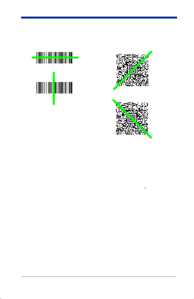
The 4800p’s viewfinder projects a green aiming beam that should be centered
Linear bar code 2D Matrix symbol
over the bar code, but can be positioned in any direction for a good read.
Hold the scanner with the aiming beam centered over the bar code. The 4800p
beeps when it successfully reads a bar code. Do not move the 4800p over
another bar code until it beeps. The optimum distance between the 4800p and
the object being scanned is 2 to 5 inches (5.1 - 12.7 cm). The height from the
4800p to the stand’s tray is the proper distance.
The aiming beam is smaller when the imager is closer to the code and larger
when it is farther from the code. Symbologies with smaller bars or elements (mil
size) should be read closer to the unit. Symbologies with larger bars or elements
(mil size) should be read farther from the unit. If the code being scanned is highly
reflective (e.g., laminated), it may be necessary to tilt the code +
unwanted reflection.
5° to prevent
4800p Stand
The stand holds the 4800p at a fixed distance for capturing images or reading
bar codes on security/identification cards. The wedge insert supplied with the
stand provides the optimum angle for scanning and capturing images in most
lighting conditions. The card should be placed on the wedge with the bar code
closest to the back of the stand.
1 - 6 4800p 2D Imager User’s Guide

2
Terminal ID
Save
Terminal Interfaces
Terminal ID
If your interface is not covered by a Plug and Play bar code from Chapter 1, then
refer to Supported Terminals on page 2-2, and locate the Terminal ID number for
your PC. Scan the
code(s) from the Programming Chart inside the back cover of this manual to
program the imager for your terminal ID. Scan
For example, an IBM AT terminal has a Terminal ID of 003. You would scan the
Terminal ID
cover of this manual, then
(before scanning Save), scan the
Terminal ID
the
Note: After scanning one of these codes, you must power cycle your computer.
Terminal ID
bar code, then
bar code, scan the digits, and the
bar code below, then scan the numeric bar
0, 0, 3
from the Programming Chart inside the back
Save
. If you make an error while scanning the digits
Discard
Save
to save your selection.
code on the Programming Chart, scan
Save
code again.
4800p 2D Imager User’s Guide 2 - 1

Supported Terminals
Note: See "Imager Models" on page 1-2 to determine which interfaces apply to
your imager.
Ter minal Model(s)
USB PC Keyboard
USB Mac Keyboard
USB HID POS
USB COM Port Emulation
USB Japanese Keyboard
*Default for 4800p model
Terminal
ID
124
125
131
130*
134
2 - 2 4800p 2D Imager User’s Guide

Keyboard Country
* United States
Brazil
Czech Republic
Denmark
Finland (Sweden)
France
Germany/Austria
Greece
Hungary
Belgium
Canada (French)
Israel (Hebrew)
Scan the appropriate country code below to program the keyboard for your
country. As a general rule, the following characters are supported, but need
special care for countries other than the United States:
@ | $ # { } [ ] = / ‘ \ < > ~
4800p 2D Imager User’s Guide 2 - 3

Keyboard Country (continued)
Latin America
Norway
Poland
Portugal
Romania
Russia
SCS
Slovakia
Italy
Netherlands (Dutch)
Spain
Sweden
Switzerland (German)
2 - 4 4800p 2D Imager User’s Guide

Keyboard Country (continued)
Turkey Q
U.K.
Turkey F
Program Keyboard Country
* Regular
Caps Lock
Please refer to the Hand Held Products website (www.handheld.com) for
complete keyboard country support information and applicable interfaces. If you
need to program a keyboard for a country other than one listed above, scan the
Program Keyboard Country bar code below, then scan the numeric bar
code(s) for the appropriate country from the inside back cover, then the Save bar
code.
Keyboard Style
This programs keyboard styles, such as Caps Lock and Shift Lock.
Regular.
Regular
Caps Lock
is used when you normally have the Caps Lock key off.
is used when you normally have the Caps Lock key on.
Default =
4800p 2D Imager User’s Guide 2 - 5

Shift Lock
Shift Lock
Automatic Caps Lock
Autocaps via NumLock
Emulate External Keyboard
to U.S. keyboards).
is used when you normally have the Shift Lock key on (not common
Automatic Caps Lock
software tracks and reflects if you have Caps Lock on or off (AT and PS/2 only).
This selection can only be used with systems that have an LED which notes the
Caps Lock status.
Autocaps via NumLock
Germany, France) where the Caps Lock key cannot be used to toggle Caps
Lock. The NumLock option works similarly to the regular Auotcaps, but uses the
NumLock key to retrieve the current state of the Caps Lock.
Emulate External Keyboard
keyboard (IBM AT or equivalent).
is used if you change the Caps Lock key on and off. The
bar code should be scanned in countries (e.g.,
should be scanned if you do not have an external
Note: After scanning the Emulate External Keyboard bar code, you must power
cycle your computer.
2 - 6 4800p 2D Imager User’s Guide

Keyboard Modifiers
Control + ASCII Mode On
* Control + ASCII Mode Off
Turbo Mode On
* Turbo Mode Off
Numeric Keypad Mode On
* Numeric Keypad Mode Off
This modifies special keyboard features, such as CTRL+ ASCII codes and Turbo
Mode.
Control + ASCII Mode On:
control characters for values 00-1F. Refer to Keyboard Function
Relationships, page 10-1 for CTRL+ ASCII Values.
Turbo Mode:
drops characters, do not use Turbo Mode.
Numeric Keypad Mode:
numeric keypad.
The imager sends characters to a terminal faster. If the terminal
Default = Off
The imager sends key combinations for ASCII
Default = Off
Default = Off
Sends numeric characters as if entered from a
4800p 2D Imager User’s Guide 2 - 7

2 - 8 4800p 2D Imager User’s Guide

3
* On
Off
* High
Medium
Off
Low
Output
Good Read Indicators
Beeper – Good Read
The beeper may be programmed On or
this option off, only turns off the beeper response to a good read indication. All
error and menu beeps are still audible.
Off
in response to a good read. Turning
Default = On.
Beeper Volume – Good Read
The beeper volume codes modify the volume of the beep the imager emits on a
good read.
Default = High
4800p 2D Imager User’s Guide 3 - 1

Beeper Pitch – Good Read
Low (1600 Hz)
* Medium (3250 Hz)
High (4200 Hz)
* Normal Beep
Short Beep
Number of Pulses
The beeper pitch codes modify the pitch (frequency) of the beep the imager emits
on a good read.
Default = Medium.
Beeper Duration – Good Read
The beeper duration codes modify the length of the beep the imager emits on a
good read.
Default = Normal.
Number of Beeps – Good Read
The number of beeps of a good read can be programmed from 1 - 9. To change
the number of beeps, scan the bar code below and then scan a digit (1-9) bar
code and the
this manual.
3 - 2 4800p 2D Imager User’s Guide
Save
bar code on the Programming Chart inside the back cover of
Default = One.
 Loading...