


SPLIT TYPE ROOM AIR CONDITIONER
OPERATION MANUAL
Contents
|
CAUTIONS |
|
|
|
|
|
|
|
|
|
|
|
|
|
|
|
|
|
|
|
|
|
PARTS AND FUNCTIONS |
|
|
|
|
|
||||
|
|
|
|
|||||||
HSU-09HR03/R2(DB) |
OPERATION |
|
|
|
|
|
|
|||
|
|
|
|
|
||||||
MAINTENANCE |
|
|
|
|
|
|
|
|||
HSU-12HR03/R2(DB) |
|
|
|
|
||||||
|
|
|
||||||||
TROUBLE SHOOTING |
|
|
|
|
|
|
||||
HSM09HRAC03/R2(DB) |
|
|
||||||||
|
||||||||||
|
|
|
|
|
|
|
|
|
|
|
HSM12HRAC03/R2(DB) |
|
|
|
|
|
|
|
|
|
|
HSM18HRAC03/R2(DB) |
|
|
|
|
|
|
|
|
|
|
HSU-09HRA103/R2 |
|
|
|
|
|
|
|
|
|
|
HSU-12HRA103/R2 |
|
|
|
|
|
|
|
|
|
|
HSU-18HRA103/R2 |
|
|
|
|
|
|
|
|
|
|
1
2
3
6
7
 Please read this operation manual before using the air conditioner. Keep this operation manual for future reference.
0010523724

Parts and Functions
|
|
Indoor Unit |
|
|
|
Remote controller |
|
|
|
|
|
|
Inlet |
|
|
|
Air Purifying Filter |
16 |
|
9. ON/OFF button |
|
|
||
|
|
|
|
|
|
15 |
17 |
10. TIMER ON display |
|
||||
Inlet grille |
|
|
|
|
|
(inside) |
|
|
11. FAN SPEED display |
|
|||
|
|
|
|
|
|
|
14 |
|
|
||||
|
|
|
|
|
|
|
|
18 |
|
|
|
|
|
|
|
|
|
|
|
|
|
13 |
|
|
|
|
|
|
|
|
|
|
|
|
|
19 |
LOW MED |
HI |
AUTO |
|
|
|
|
|
|
|
|
|
|
12 |
12. LOCK display |
|
|
||
|
|
|
|
|
|
|
|
|
|
|
|||
Outlet |
|
|
|
|
|
|
|
|
20 |
|
|
||
|
|
|
|
|
|
|
11 |
13. SWING display |
|
|
|||
|
|
|
|
|
|
|
|
21 |
|
|
|||
|
|
|
|
|
|
|
|
|
14. SLEEP display |
|
|
||
|
|
|
|
|
|
|
|
|
22 |
|
|
||
|
|
|
|
|
|
|
|
|
15. HEALTH display |
|
|||
|
|
|
|
|
|
|
|
|
|
|
|||
Anion generator |
|
|
|
|
Emergency |
|
|
16. Operation mode display |
|
||||
(inside) |
|
|
|
|
|
|
23 |
Operation mode |
|
|
|
||
|
|
|
|
|
Switch |
|
AUTO COOL |
DRY FAN HEAT |
|||||
|
|
|
|
|
|
|
24 |
Remote controller |
|
|
|
||
Horizontal flap |
|
|
|
|
Vertical blade |
|
|
|
|
||||
|
|
|
|
|
25 |
17.Signal sending |
display |
|
|||||
(adjust up and down air flow |
|
|
(adjust left and |
|
|
26 |
|
||||||
Don't adjust it manually) |
|
|
|
right air flow) |
|
|
27 |
18. POWER/SOFT display |
|
||||
|
|
|
|
|
|
Display board |
|
28 |
19. TEMP display |
|
|
||
Actual indoor unit may vary from the one shown |
|
2 |
29 |
20.TIMER OFF display |
|
||||||||
|
30 |
21.CLOCK display |
|
|
|||||||||
|
|
|
|
||||||||||
in the manual, according to the product purchased. |
|
|
|
22.TEMP button |
|
|
|||||||
|
|
|
|
|
|
|
|
|
|
23. FAN button |
|
|
|
Display board |
|
|
|
|
|
|
1.CODE |
|
24.SWING button |
|
|
||
|
|
|
|
|
|
|
25. . HEALTH AIRFLOW button |
||||||
|
|
|
|
|
|
|
|
Used to select CODE A or B |
|||||
|
|
|
|
|
|
|
|
which will be displayed on |
26.FRESH button |
|
|
||
|
|
|
|
|
|
|
|
LCD.Please select A without |
27. SET button |
|
|
||
|
|
|
|
|
|
|
|
special explanation. |
|
28.POWER/SOFT button |
|
||
|
|
|
|
|
|
|
|
2.LIGHT button |
|
29. LOCK button |
|
|
|
|
|
|
|
|
|
|
|
Control the lightening and |
|
If pressed, the other buttons |
|
||
|
|
|
|
|
|
|
|
extinguishing of the indoor |
will be disabled.Press it once |
|
|||
SiJQal receiver hole |
|
HEALTH display |
|
LED display board. |
|
again,lock will be cancelled. |
|
||||||
|
|
|
30. RESET button |
|
|
||||||||
COOL display |
|
|
(If the unit which you purchased |
3. TIMER button |
|
|
|
||||||
|
|
has healthy function,follow it. |
4. CLOCK button |
|
When the remote controller |
|
|||||||
HEAT display |
|
|
If not,please ignore.) |
|
5. SLEEP button |
|
appears abnormal,use a |
|
|||||
|
|
Dry display |
|
6. MODE button |
|
sharp pointed article to press |
|
||||||
TEMP display |
|
|
|
TIMER OFF display |
7. HOUR button |
|
this button to reset the remote |
|
|||||
|
|
|
|
|
|||||||||
|
|
|
|
|
TIMER ON display |
8. HEALTH button |
|
controller normal. |
|
|
|||
|
|
|
|
|
SLEEP display |
|
The following functions and related displays are not available: 1 |
26 |
|||||
 Outdoor Unit
OUTLET |
CONNECTING PIPING AND ELECTRICAL WIRING |
INLET |
DRAIN HOSE |
 Clock set
Press CLOCK button, "AM" or "PM" flashes.
Press or
or to set correct time. Each press will increase or decrease 1min. If the button is kept pressed,time will change quickly. After time setting is confirmed,press SET, "AM "and "PM" stop flashing,while clock starts working.
LIGHT button is not available for HSU-09HRA103/R2 and HSU-12HRA103/R2.
 Loading of the battery
1 Remove the battery cover;
2 Load the batteries as illustrated.
|
|
2 R-03 batteries, resetting key |
|
|
(cylinder); |
|
|
3Be sure that the loading |
|
|
is in line with the" + "/"-"; |
4Load the battery,then put on the cover again.
Note:
 The distance between the signal transmission head and the receiver hole should be within 7m without any obstacle as well.
 When electronic-started type fluorescent lamp or change-over type fluorescent lamp or wireless telephone is installed in the room, the receiver is apt to be disturbed in receiving the signals,
so the distance to the indoor unit should be shorter.
 Full display or unclear display during operation indicates the batteries have been used up.Please change batteries.
 If the remote controller can't run normally during operation, please remove the batteries and reload several minutes later.
Hint:
Remove the batteries in case unit won't be in usage for a long period. If there are any display after taking-out, just need to press reset key.
2
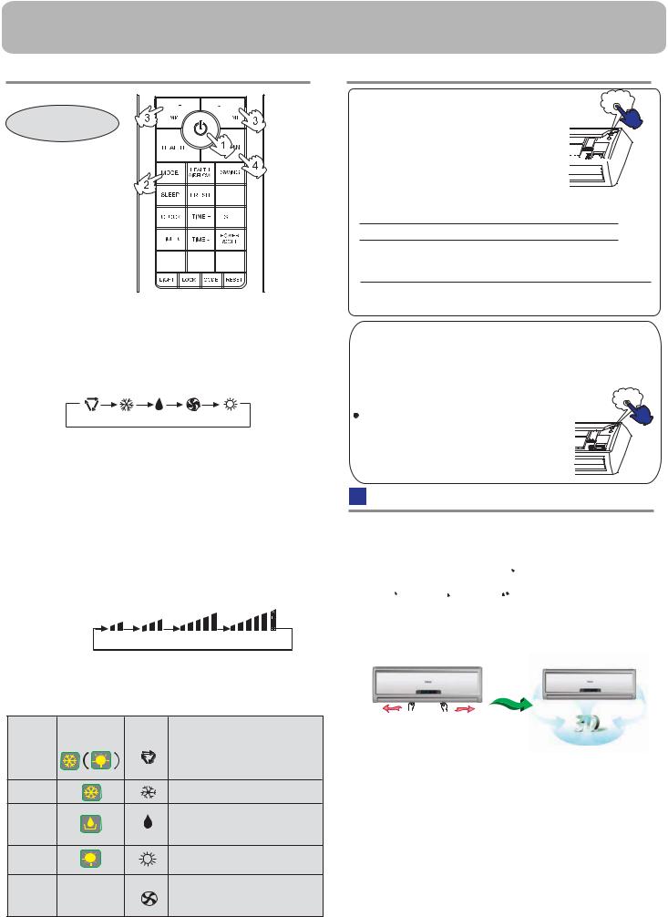
Operation
 Base Operation
Remote controller
1. Unit start
Press ON/OFF on the remote controller, unit starts.
2.Select operation mode
Press MODE button. For each press, operation mode changes as follows:
Remote controller:
AUTO COOL DRY FAN HEAT
button
TEMP+ Every time the button is pressed, temp.setting increase 1oC,if kept depressed, it will increase rapidly
Every time the button is pressed, temp.setting decrease 1oC,if kept depressed, it will decrease rapidly
Select a desired temperature.
4.Fan speed selection
Press FAN button. For each press, fan speed changes as follows:
Remote controller:
LOW MED HI AUTO
Air conditioner is running under displayed fan speed. When FAN is set to AUTO, the air conditioner automatically adjusts the fan speed according to room temperature.
Operation |
Display Board |
Remote |
Note |
Mode |
|
Controller |
|
|
|
|
Under the mode of auto operation, air conditioner |
AUTO |
|
|
will automatically select Cool or Heat operation |
|
|
according to room temperature. When FAN is set |
|
|
|
|
to AUTO, the air conditioner automatically adjusts |
|
|
|
the fan speed according to room temperature. |
COOL
In DRY mode, when room temperature becomes lower than temp.setting+2oC, unit will run
DRY intermittently at LOW speed regardless of FAN setting.
HEAT
|
|
In FAN operation mode , the unit will not operate in |
FAN |
nothing |
COOL or HEAT mode but only in FAN mode , |
AUTO is not available in FAN mode. And temp. |
||
setting is disabled. In FAN mode, sleep operation |
||
|
|
is not available. |
 Emergency operation and test operation
Emergency Operation: |
Pi |
 Use this operation only when the remote controller is defective or lost.
 When the emergency operation switch is pressed,the" Pi "sound is heard once, which
means the start of this operation. 


 In this operation, the system automatically selects

the operation modes,cooling or fan or heat, according to the room. temperature.
|
Room |
Operation |
Designated |
Timer |
|
Air flow |
|
||||
|
temperature |
mode |
|
temperature |
mode |
|
|
||||
|
|
|
|
|
|
||||||
|
ABOVE 23OC |
COOLING |
|
26OC |
|
NO |
|
AUTOMATIC |
|
||
|
BELOW 23OC |
HEAT |
|
23OC |
|
NO |
|
AUTOMATIC |
|
||
|
|
|
|
|
|
|
|
|
|
|
|
|
|
|
|
|
|
|
|
||||
|
(Cooling only uint |
|
Operation |
Designated |
Timer |
Air flow |
|||||
|
Room temperature |
|
|
mode |
temperature |
mode |
|||||
|
BELOW 23OC |
|
|
FAN |
|
26OC |
NO |
AUTOMATIC |
|||
 It is not possible to operate in dry mode.
Test operation:
Test operation switch is the same as emergency switch.
 Use this switch in the test operation when the room temperature is below 16oC, do not use it in the
normal operation. |
Pi Pi |
|
|
Continue to press the test operation |
|
switch for more than 5 seconds. After |
|
you hear the "Pi" sound twice, release |
|
your finger from the switch: the cooling |
|
operation starts with the air flow speed "Hi".
Air Flow Direction Adjustment
1.Status display of air flow
Vertical flap
Pos.1 
 Pos.2
Pos.2  Pos.3
Pos.3 
Pos.4  Pos.5
Pos.5  Pos.6
Pos.6 

 (Auto swing)
2.Left and right air flow adjustment(manual)
Move the vertical blade by a knob on air conditioner to adjust left and right direction referring to Fig.
Cautions:
 When adjusting the flap by hand,turn off the unit.
  When humidity is high,condensate water might occur at air outlet if all vertical louvers are adjusted to left or right.
 It is advisable not to keep horizontal flap at downward position for a long time in COOLor DRY mode , otherwise, condensate water might occur.
Note:
When restart after remote turning off, the remote controller will automatically memorize the previous set swing position.
3
 Loading...