


INSTALLATION MANUAL
MANUAL DE INSTALACIÓN
MANUALE DI INSTALLAZIONE
NOTICE D'INSTALLATION
ROOM AIR CONDITIONER
WALL MOUNTED TYPE
Indoor unit: HSM07HEA03/R2(DB)
HSM09HEA03/R2(DB)
HSM12HEA03/R2(DB)
Outdoor unit: 3HUM20HA03/R2(DB)
Read this manual before installation
Explain sufficiently the operating means to the user according to this manual.
NO.0010520386
Necessary Tools for Installation
1.Driver |
5.Torque wrench(17mm,22mm,26mm) |
9.Nipper |
12.Reamer |
2.Hacksaw |
6.Pipe cutter |
10.Gas leakage detector or |
|
3.Hole core drill |
7.Flaring tool |
soap-and-water solution |
|
4.Spanner(17,19 and 26mm) |
8.Knife |
11.Measuring tape |
|
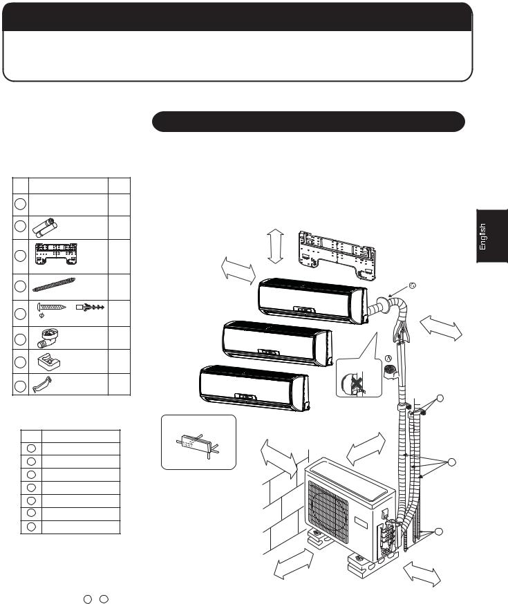
Drawing for the installation of indoor and outdoor units
Accessory parts
No. |
Accessory parts |
Number |
||
of |
||||
|
|
|
|
articles |
1 |
Remote controller |
1 |
||
2 |
|
R-03 dry battery |
2 |
|
3 |
|
|
|
1 |
|
|
|
Mounting plate |
|
4 |
|
|
Drain hose |
1 |
|
|
|
|
|
5 |
4X25 |
Plastic cap |
4 |
|
|
Screw |
|
|
|
|
|
|
|
|
6 |
|
|
Drain-elbow |
1 |
7 |
|
|
Cushion |
4 |
8 |
Pipe supporting plate |
1 |
||
|
||||
Optional parts for piping |
|
|||
Mark |
|
Parts name |
|
|
ANon-adhesive tape
BAdhesive tape
CSaddle(L.S) with screws
DConnecting electric cable for indoor and outdoor
EDrain hose
F Heating insulating material
GPiping hole cover
The models adopt HFC free refrigerant R410A
than more 5cm
more |
than |
10cm |
|
||
|
|
Indoor unit A
Indoor unit B
Indoor unit C
Arrangement of piping directions
|
Rear left |
Left |
Rear |
|
right |
|
Right |
more |
than |
|
Below |
|
10cm |
||
|
|
|||
|
|
|
||
|
|
|
|
|
than |
60cm |
|
|
|
more |
|
|
more |
than |
10cm |
|
||
|
|
Attention must be paid to the rising up of drain hose
 C
C
|
than |
10cm |
|
|
|
more |
|
|
D
E
more |
than |
15cm |
|
||
|
|
 The marks from A to G in the figure are the parts numbers.
 The distance between the indoor unit and the floor should be more than 2m.
1
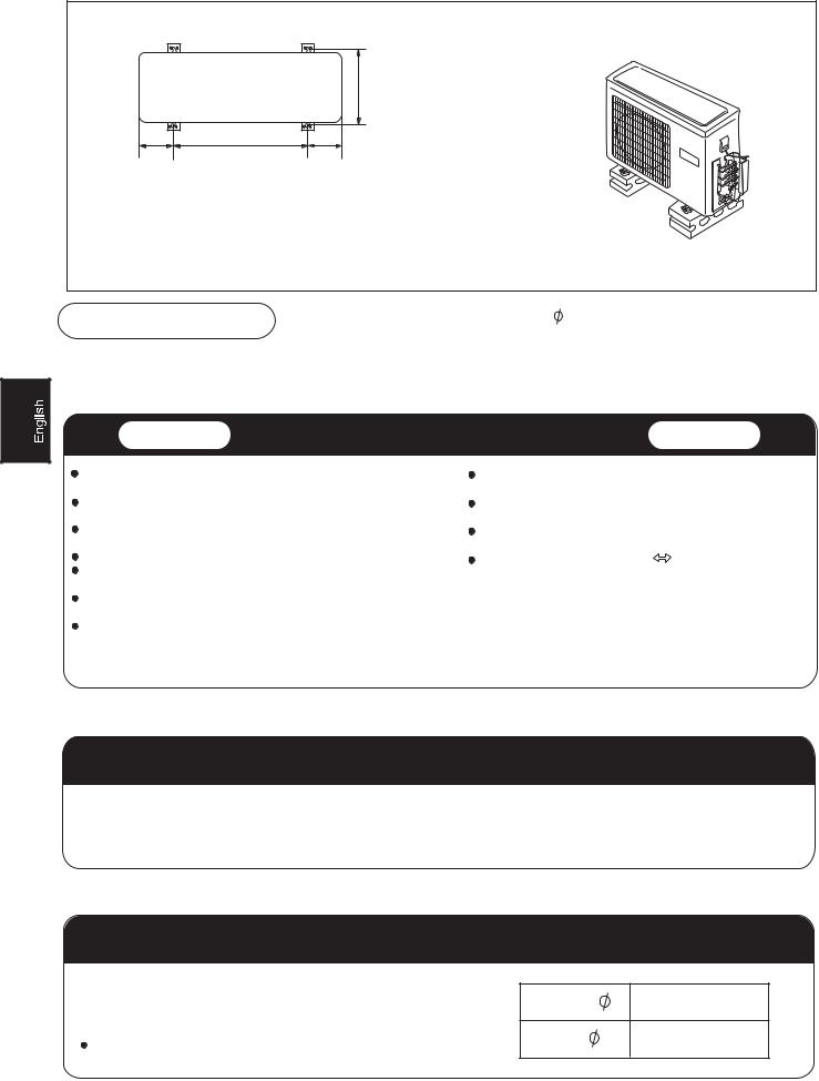
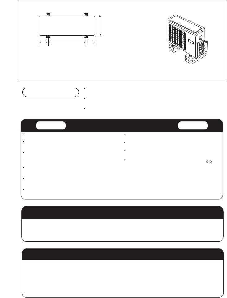
305
86.5633 86.5
)ORRU IL[LQJ GLPHQVLRQV RI WKH RXWGRRU XQLW8QLW PP
)L[LQJ RI RXWGRRU XQLW
 )L[ WKH XQLW WR FRQFUHWH RU EORFN ZLWK EROWV PP DQG QXWV ILUPO\ DQG KRUL]RQWDOO\
  :KHQ ILWWLQJ WKH XQLW WR ZDOO VXUIDFH URRI RU URRIWRS IL[ D VXSSRUWHU VXUHO\ ZLWK QDLOV RU ZLUHV LQ FRQVLGHUDWLRQ RI HDUWKTXDNH DQG VWURQJ ZLQG
 ,I YLEUDWLRQ PD\ DIIHFW WKH KRXVH IL[ WKH XQLW E\ DWWDFKLQJ D YLEUDWLRQ SURRI PDW
,QGRRU 8QLW |
6HOHFWLRQ RI ,QVWDOODWLRQ 3ODFH |
2XWGRRU 8QLW |
|
3ODFH UREXVW QRW FDXVLQJ YLEUDWLRQ ZKHUH WKH ERG\ FDQ EH VXSSRUWHG |
3ODFH ZKLFK LV OHVV DIIHFWHG E\ UDLQ RU GLUHFW VXQOLJKW DQG LV |
||
VXIILFLHQWO\ |
|
VXIILFLHQWO\ YHQWLODWHG |
|
3ODFH QRW DIIHFWHG E\ KHDW RU VWHDP JHQHUDWHG LQ WKH YLFLQLW\ ZKHUH |
3ODFH SRVVLEOH WR EHDU WKH XQLW ZKHUH YLEUDWLRQ DQG QRLVH DUH |
||
LQOHW DQG RXWOHW RI WKH XQLW DUH QRW GLVWXUEHG |
QRW LQFUHDVHG |
|
|
3ODFH SRVVLEOH WR GUDLQ HDVLO\ ZKHUH SLSLQJ FDQ EH FRQQHFWHG ZLWK WKH |
3ODFH ZKHUH GLVFKDUJHG ZLQG DQG QRLVH GR QRW FDXVH D |
||
RXWGRRU XQLW |
|
QXLVDQFH WR WKH QHLJKERUV |
|
3ODFH ZKHUH FROG DLU FDQ EH VSUHDG LQ D URRP HQWLUHO\ |
3ODFH ZKHUH D GLVWDQFH PDUNHG LV DYDLODEOH DV LOOXVWUDWHG |
||
3ODFH QHDUE\ D SRZHU UHFHSWDFOH ZLWK HQRXJK VSDFH DURXQG 5HIHU |
LQ WKH DERYH ILJXUH |
|
|
WR GUDZLQJV |
|
|
|
3ODFH ZKHUH WKH GLVWDQFH RI PRUH WKDQ OP IURP WHOHYLVLRQV UDGLRV |
|
|
|
ZLUHOHVV DSSDUDWXVHV DQG IOXRUHVFHQW ODPSV FDQ EH OHIW |
|
|
|
,Q WKH FDVH RI IL[LQJ WKH UHPRWH FRQWUROOHU RQ D ZDOO SODFH ZKHUH WKH |
|
|
|
LQGRRU XQLW FDQ UHFHLYH VLJQDOV ZKHQ WKH IOXRUHVFHQW ODPSV LQ WKH URRP
DUH OLJKWHQHG
3RZHU 6RXUFH
 %HIRUH LQVHUWLQJ SRZHU SOXJ LQWR UHFHSWDFOH FKHFN WKH YROWDJH ZLWKRXW IDLO 7KH SRZHU VRXUFH LV WKH VDPH DV WKH FRUUHVSRQGLQJ QDPH SODWH
 ,QVWDOO DQ H[FOXVLYH EUDQFK FLUFXLW RI WKH SRZHU
 $ UHFHSWDFOH VKDOO EH VHW XS LQ D GLVWDQFH ZKHUH WKH SRZHU FDEOH FDQ EH UHDFKHG 'R QRW H[WHQG WKH FDEOH E\ FXWWLQJ LW
6HOHFWLRQ RI SLSH
 7R WKLV XQLW ERWK OLTXLG DQG JDV SLSHV VKDOO EH LQVXODWHG
DV WKH\ EHFRPH ORZ WHPSHUDWXUH LQ RSHUDWLRQ
 8VH RSWLRQDO SDUWV IRU SLSLQJ VHW RU SLSHV FRYHUHG ZLWK .KSWKF RKRG OO HTXLYDOHQW LQVXODWLRQ PDWHULDO
)CU RKRG OO
7KH WKLFNQHVV RI WKH SLSH PXVW EH PP DW OHDVW
2
,QGRRU XQLW
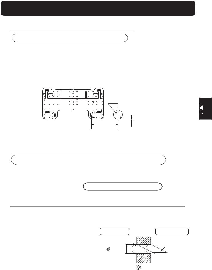
)LWWLQJ RI WKH 0RXQWLQJ 3ODWH DQG 3RVLWLRQLQJ RI WKH ZDOO +ROH
:KHQ WKH PRXQWLQJ SODWH LV ILUVW IL[HG
&DUU\ RXW EDVHG RQ WKH QHLJKERULQJ SLOODUV RU OLQWHOV D SURSHU OHYHOLQJ IRU WKH SODWH WR EH
IL[HG DJDLQVW WKH ZDOO WKHQ WHPSRUDULO\ IDVWHQ WKH SODWH ZLWK RQH VWHHO QDLO0DNH VXUH RQFH PRUH WKH SURSHU OHYHO RI WKH SODWH E\ KDQJLQJ D WKUHDG ZLWK D ZHLJKW IURP
WKH FHQWUDO WRS RI WKH SODWH WKHQ IDVWHQ VHFXUHO\ WKH SODWH ZLWK WKH DWWDFKPHQW VWHHO QDLO)LQG WKH ZDOO KROH ORFDWLRQ $ XVLQJ D PHDVXULQJ WDSH
%  PP
PP
$ PP
PP
:KHQ WKH PRXQWLQJ SODWH LV IL[HG VLGH EDU DQG OLQWHO
 )L[ WR VLGH EDU DQG OLQWHO D PRXQWLQJ EDU :KLFK LV VHSDUDWHO\ VROG DQG WKHQ IDVWHQ WKH SODWH WR WKH IL[HG PRXQWLQJ EDU
 5HIHU WR WKH SUHYLRXV DUWLFOH :KHQ WKH PRXQWLQJ SODWH LV ILUVW IL[HG IRU WKH SRVLWLRQ RI ZDOO KROH
0DNLQJ D +ROH RQ WKH :DOO DQG )LWWLQJ WKH 3LSLQJ +ROH &RYHU
 0DNH D KROH RI PP LQ GLDPHWHU VOLJKWO\ GHVFHQGLQJ WR RXWVLGH WKH ZDOO
  ,QVWDOO SLSLQJ KROH FRYHU DQG VHDO LW
RII ZLWK SXWW\ DIWHU LQVWDOODWLRQ |
,QGRRU VLGH |
2XWGRRU VLGH |
|
:DOO KROH |
7KLFNQHVV |
|
PP |
RI ZDOO |
|
|
|
|
6HFWLRQ RI ZDOO KROH |
3LSLQJ KROH SLSH |
,QGRRU XQLW
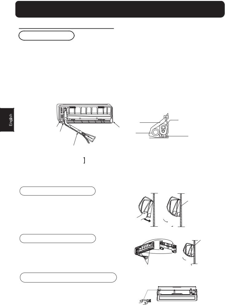
,QVWDOODWLRQ RI WKH ,QGRRU 8QLW
'UDZLQJ RI SLSH
 5HDU SLSLQJ
 'UDZ SLSHV DQG WKH GUDLQ KRVH WKHQ IDVWHQ WKHP ZLWK WKH DGKHVLYH WDSH
 /HIW
/HIW  /HIW UHDU SLSLQJ
 ,Q FDVH RI OHIW VLGH SLSLQJ FXW DZD\ ZLWK D QLSSHU WKH OLG IRU OHIW SLSLQJ
 ,Q FDVH RI OHIW UHDU SLSLQJ EHQG WKH SLSHV DFFRUGLQJ WR WKH SLSLQJ GLUHFWLRQ WR WKH PDUN RI KROH IRU OHIW UHDU SLSLQJ ZKLFK LV PDUNHG RQ KHDW LQVXODWLRQ PDWHULDOV,QVHUW WKH GUDLQ KRVH LQWR WKH GHQW RI KHDW LQVXODWLRQ PDWHULDOV RI LQGRRU XQLW,QVHUW WKH LQGRRU RXWGRRU HOHFWULF FDEOH IURP EDFNVLGH RI LQGRRU XQLW DQG SXOO LW RXW RQ WKH IURQW VLGH WKHQ
FRQQHFW WKHP&RDW WKH IODULQJ VHDO IDFH ZLWK UHIULJHUDQW RLO DQG FRQQHFW SLSHV
&RYHU WKH FRQQHFWLRQ SDUW ZLWK KHDW LQVXODWLRQ PDWHULDOV FORVHO\ DQG PDNH VXUH IL[LQJ ZLWK DGKHVLYH WDSH
|
+HDW LQVXODWLRQ |
3LSLQJ |
|
PDWHULDO |
|
/LG IRU ULJKW SLSLQJ |
/LG IRU OHIW SLSLQJ |
|
|
,QGRRU RXWGRRU |
|
/LG IRU XQGHU SLSLQJ |
'UDLQ KRVH |
|
|
HOHFWULF FDEOH |
|
|
|
)L[ ZLWK DGKHVLYH WDSH
 ,QGRRU RXWGRRU HOHFWULF FDEOH DQG GUDLQ KRVH PXVW EH ERXQG ZLWK UHIULJHUDQW SLSLQJ E\ SURWHFWLQJ WDSH
 2WKHU GLUHFWLRQ SLSLQJ
 &XW DZD\ ZLWK D QLSSHU WKH OLG IRU SLSLQJ DFFRUGLQJ WR WKH SLSLQJ GLUHFWLRQ DQG WKHQ EHQG WKH SLSH DFFRUGLQJ
WR WKH SRVLWLRQ RI ZDOO KROH :KHQ EHQGLQJ EH FDUHIXO QRW WR FUDVK SLSHV  &RQQHFW EHIRUHKDQG WKH LQGRRU RXWGRRU HOHFWULF FDEOH DQG WKHQ SXOO RXW WKH FRQQHFWHG WR WKH KHDW LQVXODWLRQ RI FRQQHFWLQJ SDUW VSHFLDOO\
)L[LQJ WKH LQGRRU XQLW ERG\
 +DQJ VXUHO\ WKH XQLW ERG\ RQWR WKH XSSHU QRWFKHV RI WKH
PRXQWLQJ SODWH 0RYH WKH ERG\ IURP VLGH WR VLGH WR YHULI\
LWV VHFXUH IL[LQJ
 ,Q RUGHU WR IL[ WKH ERG\ RQWR WKH PRXQWLQJ SODWH KROG XS
WKH ERG\ DVODQW IURP WKH XQGHUVLGH DQG WKHQ SXW LW GRZQ
SHUSHQGLFXODUO\
8QORDGLQJ RI LQGRRU XQLW ERG\
 :KHQ \RX XQORDG WKH LQGRRU XQLW SOHDVH XVH \RXU KDQG WR DULVH
WKH ERG\ WR OHDYH DJUDIIH WKHQ OLIW WKH ERWWRP RI WKH ERG\ RXWZDUG
VOLJKWO\ DQG OLIW WKH XQLW DVODQW XQWLO LW OHDYHV WKH PRXQWLQJ SODWH
DJUDIIH
PRXQWLQJ SODWH
PRXQWLQJ SODWH
(DVLO\ GHPRXQW FOHDQLQJ RI LQGRRU XQLW
,QOHW JULOOH FDQ EH WDNHQ GRZQ
2SHQ WKH LQOHW JULOOH SUHVV WKH EXWWRQ RI XQORFN LQ WKH OHIW WKHQ SXVK LW RXW RI WKH VRFNHW DQG WDNH RXW WKH LQOHW JULOOH
4
Indoor unit
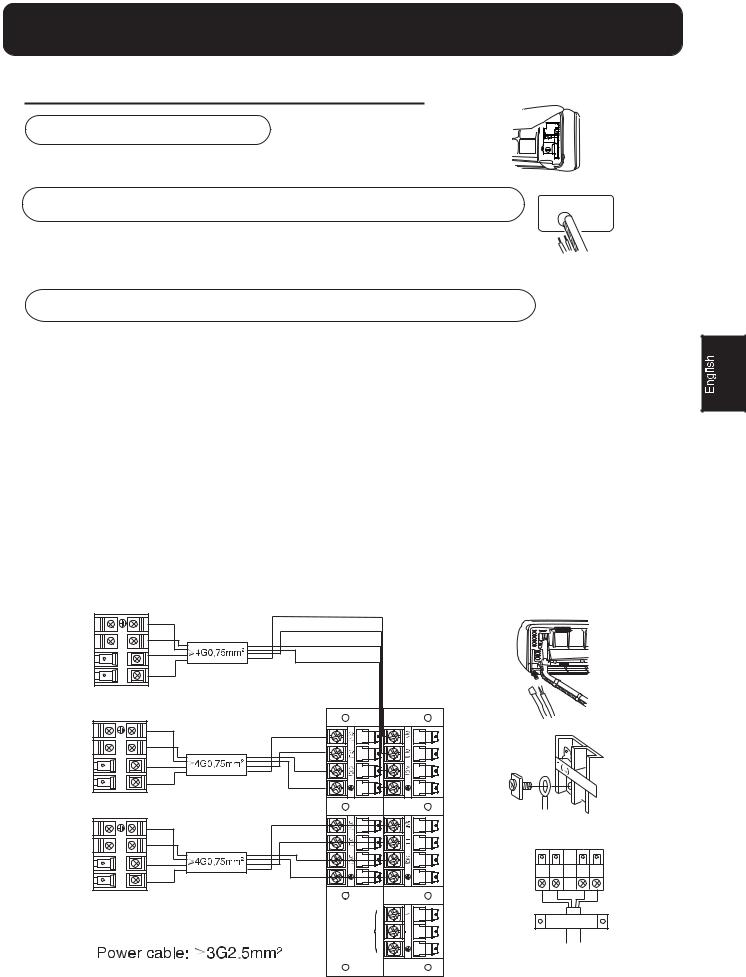
4.Connecting the indoor/outdoor Electric Cable
Removing the wiring cover
 Remove terminal cover at right bottom corner of indoor unit, then take off wiring cover by removing its screws.
When connecting the cable after installing the indoor unit
1. Insert from outside the room cable into left side of the wall hole, in which the pipe has already existed.
2. Pull out the cable on the front side, and connect the cable making a loop.
When connecting the cable before installing the indoor unit
 Insert the cable from the back side of the unit, then pull it out on the front side.
 Loosen the screws and insert the cable ends fully into terminal block, then tighten the screws.
 Pull the cable slightly to make sure the cables have been properly inserted and tightened.
 After the cable connection, never fail to fasten the connected cable with the wiring cover.
Note: When connecting the cable, confirm the terminal number of indoor and outdoor units carefully. If wiring is not correct, proper operation can not be carried out and will cause defect.
1.If the supply cord is damaged, it must be replaced by the manufacturer or its service agent or a similar qualified person. The type of connecting wire is H05/07RN-F or 245IEC57(YZW).
2.If the fuse on PC board is broken please change it with the type of T. 3.15A/250V.
3.The wiring method should be in line with the local wiring standard.
4.After installation, the power plug should be easily reached.
5.A breaker should be incorporated into fixed wiring. The breaker should be all-pole switch and the distance between its two contacts should be not less than 3mm.
Indoor unit A
3(C) |
1(N)2(L) |
Indoor unit C
3(C) |
1(N)2(L) |
Indoor unit B
3(C) |
1(N)2(L) |
WOP |
RE |
Outdoor unit
5
Outdoor unit
1.Installation of Outdoor Unit
Install according to Drawing for the installation of indoor and outdoor units
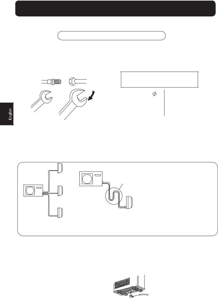
2.Connection of pipes
 To bend a pipe, give the roundness as large as possible not to crush the pipe ,and the bending radius should be 30 to 40 mm or longer.
 Connecting the pipe of gas side first makes working easier.
  The connection pipe is specialized for R410A.
Half union |
Flare nut |
Spanner |
Torque wrench |
Forced fastening without careful centering may damage the threads and cause a leakage of gas.
Pipe Diameter ( ) |
Fastening torque |
||
|
|
|
|
Liquid side 6.35mm(1/4") |
18N.m |
||
|
|
|
|
Gas side |
9.52mm(3/8") |
40N.m |
|
|
|
|
|
Gas side |
12.7mm(1/2") |
55N.m |
|
Be careful that matters, such as wastes of sands, etc. shall not enter the pipe.
The standard pipe length is 15m. If it is over 30m, the function of the unit will be affected. If the pipe has to be lengthened, the refrigerant should be charged, according to 20 g/m. But the charge of refrigerant must be conducted by professional air conditioner engineer. Before adding additional refrigerant, perform air purging from the refrigerant pipes and indoor unit using a vacuum pump,then charge additional refrigerant.
For the 1by 3 models which outdoor unit capacity is 20000 BTU , the standard pipe length of single indoor unit
is 5 meters, triple units is 15 meters. If total pipe length is more than30 metres, charge more refrigerant is needed.
Indoor unit
Outdoor unit
Indoor unit
Indoor unit
Max.Elevation:15m
Outdoor unit
Max. Length:A=45m
A |
Oil trap |
|
|
|
Indoor unit |
CAUTION
 In case more than 5m
 Oil trap shoud be installed every 5~7m
 no more gas if the length of connecting pipe is less than30m
 The height difference between any two indoor or outdoor units can not be more than 15 metres
 The length ofconnecting pipe of one units must less than 20 metres
3.Connection
 Use the same method on indoor unit. Loosen the screws on terminal block and insert the plugs fully into terminal block, then tighten the screws.
 Insert the cable according to terminal number in the same manner as the indoor unit.
 If wiring is not correct, proper operation can not be carried out and controller may be damaged.
 Fix the cable with a clamp.
4.Attaching Drain-Elbow
 If the drain-elbow is used, please attach it as figure. (Note: Only for heat pump unit.)
6
Outdoor unit
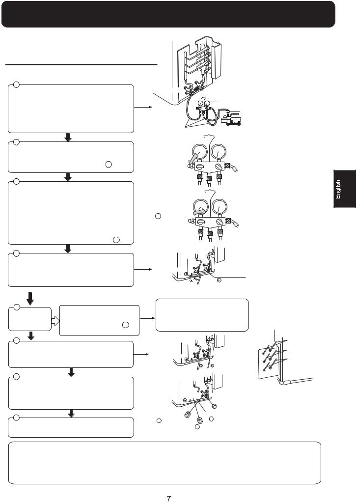
3XUJLQJ 0HWKRG 7R XVH YDFXXP SXPS |
|
||
|
ZD\ YDOYH / |
ZD\ YDOYH * |
|
'HWDFK WKH VHUYLFH SRUW V FDS RI ZD\ * YDOYH WKH |
|||
|
|||
|
|
||
YDOYH URG V FDS IRU ZD\ / YDOYH DQG ZD\ V * FRQQHFW |
|
*DXJHPDQLIROG IRU 5 $ |
|
WKH VHUYLFH SRUW LQWR WKH SURMHFWLRQ RI FKDUJH KRVH |
|
||
|
$QWL FRXQWHUFXUUHQW MRLQW |
||
,RZ IRU JDXJHPDQLIROG 7KHQ FRQQHFW WKH SURMHFWLRQ |
|
||
|
|
||
RI FKDUJH KRVH FHQWHU IRU JDXJHPDQLIROG LQWR |
|
|
|
YDFXXP SXPS |
7XEH IRU 5 $ |
9DFXXP SXPS IRU 5 $ |
|
2SHQ WKH KDQGOH DW ,RZ LQ JDXJHPDQLIROG RSHUDWH YDFXXP SXPS ,I WKH VFDOH PRYHV RI JDXVH ,RZ 
 2SHQ UHDFK YDFXXP FRQGLWLRQ LQ D PRPHQW FKHFN DJDLQ
9DFXXPL]H IRU RYHU PLQ $QG FKHFN WKH OHYHO JDXJH ZKLFK VKRXOG UHDG 03D FP +J DW ,RZ SUHVVXUH VLGH $IWHU WKH FRPSOHWLRQ RI YDFXXPL]LQJ
FORVH WKH KDQGOH /R LQ JDXJHPDQLIROG DQG VWRS WKH
RSHUDWLRQ RI WKH YDFXXP SXPS 
 &ORVH
&ORVH
&KHFN WKH FRQGLWLRQ RI WKH VFDOH DQG KROG LW IRU PLQ
,I WKH VFDOH PRYHV EDFN LQ VSLWH RI WLJKWHQLQJ PDNH IODULQJ ZRUN DJDLQ WKH UHWXUQ WR WKH EHJLQQLQJ RI
|
|
|
|
|
2SHQ WKH YDOYH URG IRU WKH ZD\ / YDOYH WR DQ DQJOH RI |
|
|
|
|
DQWLFORFNZLVH GHJUHHV |
ZD\ YDOYH / |
ZD\ YDOYH * |
||
$IWHU VHFRQGV FORVH WKH ZD\ / YDOYH DQG PDNH |
6HUYLFH SRUW |
|||
2SHQ |
||||
WKH LQVSHFWLRQ RI JDV OHDNDJH |
R |
|
||
R |
|
IRU VHF |
||
,Q FDVH RI JDV OHDNDJH WLJKWHQ
SDUWV RI SLSH FRQQHFWLRQ ,I
1R JDV OHDNDJH"
OHDNDJH VWRSV WKHQ SURFHHG VWHSV
'HWDFK WKH FKDUJH KRVH IURP WKH VHUYLFH SRUW RSHQZD\ / YDOYH DQG ZD\ * 7XUQ WKH YDOYH URG DQWLFORFNZLVH XQWLO KLWWLQJ OLJKWO\
7R SUHYHQW WKH JDV OHDNDJH WXUQ WKH VHUYLFH SRUW V FDS WKH YDOYH URG V FDS IRU ZD\ / YDOYH DQG ZD\ V * D OLWWOH PRUH WKDQ WKH SRLQW ZKHUH WKH WRUTXH LQFUHDVHV VXGGHQO\
$IWHU DWWDFKLQJ WKH HDFK FDSV FKHFN WKH JDV OHDNDJH DURXQG WKH FDSV
,I LW GRHV QRW VWRS JDV OHDNDJH GLVFKDUJH ZKROH UHIULJHUDQWV IURP WKH VHUYLFH SRUW $IWHU IODULQJ ZRUN DJDLQ DQG YDFXXPL]H ILOO XS SUHVFULEHG UHIULJHUDQW IURP WKH JDV F\OLQGHU
ZD\ YDOYH *
ZD\ YDOYH /
 ZD\ YDOYH /

 ZD\ YDOYH *

 9DOYH URG FDS
 6HUYLFH SRUW FDS
  9DOYH URG FDS
  6HUYLFH SRUW FDS
7R LQGRRU XQLW $
7R LQGRRU XQLW %
7R LQGRRU XQLW &
&$87,21,I WKH UHIULJHUDQW RI WKH DLU FRQGLWLRQHU OHDNV LW LV QHFHVVDU\ WRGLVFKDUJH DOO WKH UHIULJHUDQW 9DFXXPL]H ILUVW WKHQ FKDUJH WKH OLTXLGUHIULJHUDQW LQWR DLU FRQGLWLRQHU DFFRUGLQJ WR WKH DPRXQW PDUNHG RQWKH QDPH SODWH
3OHDVH GR QRW OHW RWKHU FRROLQJ PHGLXP H[FHSW VSHFLILHG RQH 5 $RU DLU HQWHU LQWR WKH FRROLQJ FLUFXODWLRQ V\VWHP 2WKHUZLVH WKHUH ZLOO EHDEQRUPDO KLJK SUHVVXUH LQ WKH V\VWHP WR PDNH LW FUDFN DQG OHDG WRSHUVRQDO LQMXULHV
1.Power Source Installation
 The power source must be exclusively used for air conditioner. (Over I0A)
 In the case of installing an air conditioner in a moist place, please install an earth leakage breaker.
 For installation in other places, use a circuit breaker as far as possible.
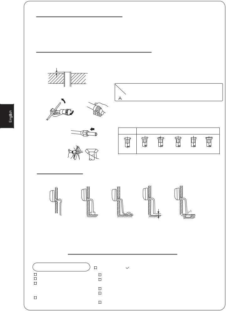
2.Cutting and Flaring Work of Piping
 Pipe cutting is carried out with a pipe cutter and burs must be removed.
  After inserting the flare nut, flaring work is carried out.
A |
Flare tooling die |
1.Cut pipe |
2.Remove burs |
|
Flare tool for R410A |
Conventional flare tool |
|
|
|
|
|
|
Clutch-type |
clutch-type(Rigid-type) |
Wing-nut type (Imperial-type) |
|
|
|
|
|
0~0.5mm |
1.0~1.5mm |
1.5~2.0mm |
|
|
|
|
3.Insert the flare nut
Correct |
Incorrect |
4.Flare pipe
Lean Damage of flare Crack Partial Too outside
3.On Drainage
Please install the drain hose so as to be downward slope without fail. Please don't do the drainage as shown below.
Less than 5cm |
It becomes high midway. |
The end is immersed |
It waves. |
The gap with the ground |
|
in water. |
|
is too small |
There is the bad smell from a ditch
 Please pour water in the drain pan of the indoor unit, and confirm that drainage is carried out surely to outdoor.
 In case that the attached drain hose is in a room, please apply heat insulation to it without fail.
Check for Installation and Test Run
 Please kindly explain to our customers how to operate through the instruction manual.
Check Items for Test Run |
Put check mark |
in boxes |
Gas leak from pipe connecting? |
Is drainage securely carried out? |
|
Heat insulation of pipe connecting? |
Is the earth line securely |
|
Are the connecting wirings of |
connected? |
|
indoor and outdoor firmly inserted |
Is the indoor unit securely fixed? |
|
to the terminal block? |
Is power source voltage abided |
|
Is the connecting wiring of indoor |
by the code? |
|
and outdoor firmly fixed? |
Is there any noise? |
|

 Is the lamp normally lighting?

 Are cooling and heating (when
in heat pump) performed normally?

 Is the operation of room temperature regulator normal?
8

Herramientas necesarias para realizar la instalación
1. |
Destornillador |
5. |
Llave dinamométrica (17 mm, 22 mm, 26 |
9. Pinzas |
12. Avellanador |
|
|
mm) |
|
|
|
2. |
Sierra para metales |
6. |
Cortador de tubo |
10. Detector de fugas de gas o |
|
3. |
Taladro |
7. |
Llave para tuercas cónicas |
solución de agua jabonosa |
|
4. |
Llave (17, 19 y 26 mm) |
8. |
Cuchilla |
11. Metro |
|
|
|
|
|
|
|
Diagrama para la instalación de aparatos interiores y exteriores
Los modelos cumplen la norma R410A sobre refrigerantes libres HFC
Accesorio
Nº |
Accesorio |
Número |
|
|
|
|
|
|
|
de |
|
|
|
|
|
||
|
|
artículos |
|
|
|
|
|
|
1 |
Control remoto |
|
1 |
|
|
|
|
|
|
|
|
|
|
|
|
|
|
2 |
Batería seca R-03 |
|
2 |
|
|
|
|
|
|
|
|
|
|
|
|
||
3 |
|
|
1 |
|
m |
|
|
|
|
|
|
ás |
d |
e10 c |
|
||
|
|
|
|
|
|
|
m |
|
|
|
|
|
|
|
|
|
|
|
Placa de montaje |
|
|
|
|
|
|
|
4 |
|
|
1 |
|
Unidad exterior A |
|||
|
Manguera de drenaje |
|
|
|
|
|
|
|
5 |
Tornillo Ø4X25 Tapón |
|
4 |
|
Unidad exterior B |
|
|
|
|
de plástico |
|
|
|
|
|
|
|
6 |
Codo de drenaje |
|
1 |
|
|
|
|
|
|
|
|
|
|
|
|
|
|
7 |
Amortiguador |
|
4 |
Unidad exterior c |
|
|
|
|
8 |
|
|
1 |
|
|
|
|
|
Placa de soporte del tubo |
|
|
|
|
|
|
|
|
|
|
|
|
Organización de la dirección de los tubos |
||||
|
|
|
|
|
||||
|
|
|
|
|
Izquierda trasera |
|
||
|
|
|
|
|
Izquierda |
|
|
|
Componentes opcionales |
para |
|
Trasera derecha |
|||||
Derecha |
|
|
||||||
|
|
|
||||||
la instalación de los tubos |
|
Inferior |
|
|
|
|||
Marca Nombre del componente
Cinta no adhesiva
Cinta adhesiva
Soporte (L.S) con tornillos
Conexión de cable eléctrico para interior y
exterior
Manguera de drenaje
Material aislante de calor
Cubierta de orificio de
entubación
másde5cm
m |
|
á |
|
sd |
|
e |
|
1 |
|
0 |
c |
|
m |
|
m |
|
c |
|
0 |
e |
6 |
d |
|
s |
|
á |
|
m |
|
Las marcas de la a la que se muestran en la figura representan los números de los componentes.
La distancia entre la unidad interior y el suelo debe ser superior a 2 m.
m |
|
|
ás |
|
|
de |
|
|
1 |
0 |
cm |
|
||
|
|
Debe prestarse atención al |
|
ascenso de la manguera |
C |
de drenaje |
|
0 |
cm |
1 |
|
e |
|
d |
|
s |
D |
á |
|
m |
E
m |
|
ás |
|
de |
|
15 |
cm |
|
9
305
86.5633 86.5
Dimensiones de fijación al suelo de la unidad exterior (Unidades: mm)
Fijación de la unidad exterior
Fije la unidad a un bloque de cemento con pernos (ø10 mm) y tuercas firme y horizontalmente.
Si instala la unidad sobre una pared, techo o tejado, instale un soporte con clavos o cables considerando la posibilidad de terremotos o viento fuerte.
Si la vibración afectase a la casa, fije la unidad instalando una alfombra de absorción de vibraciones.
Unidad interior Selección del lugar de instalación Unidad exterior
Coloque la unidad sobre una superficie que pueda soportarla correctamente y no provoque vibraciones.
Asegúrese de que el lugar no se vea afectado por el calor o vapor generado en las cercanías y donde la unidad pueda funcionar sin perturbaciones.
Asegúrese de que el lugar permita un drenaje sencillo y en el que puedan conectarse los tubos a la unidad exterior. Asegúrese de que el aire frío pueda distribuirse uniformemente por la sala.
Coloque la unidad interior cerca de una toma de suministro eléctrico con espacio suficiente alrededor. (Consulte los diagramas).
Coloque la unidad interior de modo se encuentre a más de 1 m de televisiones, radios, aparatos inalámbricos y lámparas fluorescentes.
En el caso de fijar el control remoto a una pared, colóquelo donde la unidad interior pueda recibir su señal mientras estén encendidas las lámparas fluorescentes de la sala.
Seleccione el lugar menos afectado por la lluvia o la luz solar directa y suficientemente ventilado.
Elija un lugar que permita soportar el peso de la unidad y que no amplifique el ruido y las vibraciones.
Seleccione un lugar en el que los residuos y el viento generado por la unidad no cause una molestia a los vecinos.
Coloque la unidad en un lugar en el que pueda disponerse de la
distancia de separación marcada con el símbolo |
en la |
figura anterior. |
|
|
Fuente de alimentación |
 Antes de insertar el enchufe de alimentación en la toma, compruebe que el voltaje no falla. La fuente de alimentación es la que figura en la placa de datos nominales.
 Instale el aparato en un circuito dedicado de alimentación.
 Debe existir una toma al alcance del cable de alimentación. No realice cortes en el cable con el fin de prolongarlo.
|
Selección de tubo |
 En esta unidad, los tubos de líquido y gas deben aislarse debido a su baja temperatura de funcionamiento.
 Utilice componentes opcionales para conjuntos de entubación o tubos cubiertos con material de aislamiento equivalente.
 El grosor del tubo debe ser, al menos, de 0,8 mm.
Tubo de líquido (Ø) |
6,35 mm (1/4") |
|
|
Tubo de gas (Ø) |
9,52 mm (3/8") |
10
 Loading...