


P4000
Installation & Operation
®
trans |
nova |
|
®
ASSEMBLEDDESIGNED USAAND IN THE
PROFESSIONAL POWER AMPLIFIER

N O T I C E - I M P O R T A N T S A F E T Y I N F O R M A T I O N
C A U T I O N
RISK OF ELECTRIC SHOCK |
! |
DO NOT OPEN |
WARNING: TO PREVENT FIRE OR SHOCK HAZARD DO NOT EXPOSE THIS EQUIPMENT TO RAIN OR MOISTURE.
The lightning flash with arrowhead symbol within an equilateral triangle is intended to alert the user to the presence of uninsulated "dangerous voltage" within the product's enclosure, that may be of sufficient magnitude to constitute a risk of electric shock to persons.
The exclamation point within an equilateral triangle is intended to alert the user of the presence of important operating and maintenance (servicing) instructions in the literature accompanying the appliance.
1.READ INSTRUCTIONS
All the safety and operating instructions of your Hafler equipment should be read before power is applied to the equipment.
2.RETAIN OWNER'S MANUAL
These safety and operating instructions should be retained for future reference.
3.HEED WARNINGS
All warnings on the equipment and in the operating instructions are important and should be followed.
4.FOLLOW INSTRUCTIONS
All operating and use instructions are important and should be followed.
5.HEAT
The equipment should be kept away from areas of high temperature, i.e., heater vents, radiators, stoves/ovens, fireplaces, etc.
6.VENTILATION
The equipment should be used in an area suitable for proper ventilation. Care should be taken not to impede airflow in and around the cabinet.
7.WATER AND MOISTURE
The equipment should not be used in or around water, such as a bathtub, sink, or swimming area. Also, the equipment should not be used in areas prone to flooding, such as a basement.
8.POWER SOURCES
The equipment should be connected only to a power source of the same voltage and frequency as that listed on the rear panel above the power cord entry point.
9.POWER CORD PROTECTION
Power cords should be arranged so they do not interfere with the movement of objects in the room: people, fan blades, utility carts, etc. Also, care should be taken that the cord is not pinched or cut, and placed so it is not in danger of being pinched or cut, as in under a rug, around a tight corner, etc.
10.POWER CORD GROUNDING
The power supply cord is of a three wire grounded type, designed to reduce the risk of electric shock sustained from a live cabinet. It is assumed to be of suitable length for most uses of the equipment. The use of extension cords and power strips is discouraged unless they are of suitable rating to deliver the required total current for safe operation of all connected equipment. Furthermore, extension cords or power strips must provide
the same three wire grounded connection. It is important that the blades of the equipment’s plug be able to fully insert into the mating receptacle. Never remove the round grounding pin on the plug in an attempt to mate to a two wire ungrounded receptacle: use a grounding adaptor with the grounding tab or wire suitably connected to earth ground.
11.NON-USE PERIODS
During periods of extended non-use, the power cord should be unplugged from the power source.
12.CLEANING
The equipment should be cleaned only as detailed in the operating instructions.
13.OBJECT AND LIQUID ENTRY
Care should be taken so that objects and/or liquids, such as cleaning fluids or beverages, are not spilled into the enclosure of the equipment.
14.DAMAGE REQUIRING SERVICE
Hafler equipment should be serviced by qualified service personnel when:
A.The power supply cord or plug has been damaged, or
B.Objects have fallen onto, or liquid has been spilled into the equipment, or
C.The equipment has been exposed to rain, or
D.The equipment does not appear to operate normally or exhibits a marked change in performance, or
E.The equipment has been dropped, or the enclosure has been damaged.
15.SERVICING
The user should not attempt to service the equipment beyond that which is described in the operating instructions. All other service should be referred to qualified service personnel.
16.CARTS AND STANDS
The equipment should be used with carts or stands only of sufficient strength and stability for the use intended.
An equipment and cart combination should be moved with care. Quick stops and starts, excessive force, and uneven surfaces may cause the equipment and cart combination to topple.
– i –
P E R F O R M A N C E S P E C I F I C A T I O N S |
|
|
P4000 |
|
|
Power Rating: |
FTC (20Hz-20kHz, 0.2% THD) |
|
|
200 wpc into 8Ω |
|
|
275 wpc into 4Ω |
|
|
550 wpc into 8Ω (bridged mono) |
|
Signal-to-Noise Ratio: |
100dB below rated output from 20Hz-20kHz “A” Weighted |
|
Frequency Response: |
20Hz-20kHz, ± 0.1dB |
|
Bandwidth: |
0.2Hz-200kHz, +0/–3dB |
|
Slew Rate: |
100 V/µs |
|
CMRR: |
>75dB at 1kHz |
|
Input Impedance: |
47,000Ω per phase balanced |
|
Input Sensitivity Range: |
710mV to 4V (@ 8Ω) per phase balanced |
|
|
592mV to 4V (@ 4Ω) per phase balanced |
|
In/Out Gain: |
+29dB maximum, –29dB minimum |
|
Gain Control Range: |
58dB |
|
Damping Factor: |
500 (to 1kHz); 150 (to 10kHz); 18 (to 100kHz) |
|
Power Consumption: |
120W / 1A @ 120VAC (Idle Power) |
|
(Both Channels Driven) |
250W / 2.1A @ 120 VAC (1/8 Power – 8Ω ) |
|
|
720W / 6A @ 120 VAC (Max. Power – 8Ω ) |
|
Controls & Switches: |
Front Panel Gain Control, Power Switch |
|
Indicators: |
Signal LED, Clip LED, Thermal LED, Short LED, Line Power LED |
|
Connectors: |
XLR & 1/4" combo input |
|
|
5-way Binding Post output |
|
|
IEC Standard Line input |
17.00 |
|
|
|
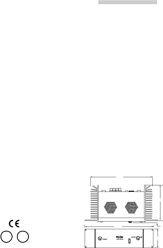
Dimensions: |
19"W x 11"D x 5-1⁄4"H (3-rack spaces) |
|
|
(48.26cm x 27.94cm x 13.34cm) |
|
Net Weight: |
34 lbs. (15.42kg) |
|
10.97
U® L C U® L
4  6
6
8
0
ch nne 1
si |
c ipping herm |
al |
hort |
|
nal |
|
|
19.00
short |
|
mal |
p ng |
|
|
B i ged |
e |
cli |
s gnal |
4 |
6 |
Mo o |
®N rmal
|
2 |
8 |
P 4 0 0 0 t r a n s • n o v a |
0 |
10 |
|
han |
el 2 |
.724
5.20
– ii –

T A B L E O F C O N T E N T S 
SAFETY PRECAUTIONS ........................................................................................................................................... |
i |
PERFORMANCE SPECIFICATIONS ......................................................................................................................... |
ii |
INTRODUCTION ................................................................................................................................................... |
1 |
FRONT & REAR PANEL VIEW ................................................................................................................................ |
2 |
INSTALLATION |
|
Location ........................................................................................................................................................... |
3 |
AC Line ............................................................................................................................................................ |
3 |
Input ................................................................................................................................................................. |
4 |
Output Connections ......................................................................................................................................... |
4 |
Monophonic Use .............................................................................................................................................. |
4 |
OPERATION |
|
Power Switch ................................................................................................................................................... |
6 |
Level Controls .................................................................................................................................................. |
6 |
Input Configuration Switch ............................................................................................................................... |
6 |
Ground Switch ................................................................................................................................................. |
7 |
Short Circuit Protection .................................................................................................................................... |
7 |
LED Indicators .................................................................................................................................................. |
7 |
Warm Up ......................................................................................................................................................... |
7 |
Cleaning and Maintenance ............................................................................................................................... |
7 |
TECHNICAL REFERENCE |
|
Field Service Considerations ............................................................................................................................. |
8 |
Theory and Operation of trans•nova ................................................................................................................ |
8 |
P4000 Functional Block Diagram ..................................................................................................................... |
9 |
Schematic Diagram ........................................................................................................................................ |
10 |
PC Board Layout ............................................................................................................................................. |
10 |
Parts List ......................................................................................................................................................... |
13 |
Circuit Operation ........................................................................................................................................... |
15 |
Amplifier Module Replacement ...................................................................................................................... |
18 |
WARRANTY ......................................................................................................................................................... |
19 |

I N T R O D U C T I O N 
The Hafler P4000 is a three rack height, two channel professional power amplifier suitable for use in any situation where a moderately powered compact amplifier is required. The P4000 is particularly attractive for use in monitoring situations. Our trans•nova circuit topology and MOSFET output stage ensures trouble-free, long term operation and is backed by our five year warranty.
This manual contains information on using the P4000 amplifier. It is organized into three main sections.
“Installation” covers the location and connection of the amplifier in the system. Like many precision components, careful attention to the initial setup can yield dividends in higher performance and trouble-free use. “Operation” covers the controls and features of the amplifiers and how to use them to get the best effect. The “Technical Reference” section contains field service information; in addition to the schematic and parts list there are block diagrams and circuit operation explanations useful for technicians. We strongly urge reading over the Installation and Operation portions of this manual before putting the amplifier into service.
The circuitry used in the Hafler Professional power amplifiers is our trans•nova (TRANSconductance Nodal
Voltage Amplifier, U.S. Patent 4,467,288) circuit. The P4000 also utilizes our proprietary DIAMOND
(Dynamically Invariant AMplification Optimized Nodal Drive, patent pending) transconductance driver stage which combines the linearity of Class A operation with the current headroom of a Class B system. When combined with the robust output stage used in the P4000, DIAMOND yields lower high frequency distortion without the sonic degradations associated with increasing the negative feedback. We have been using MOSFETs in our power amplifiers since the 1970's. During this time they have proven to be extremely fault tolerant, even in abusive situations. This ruggedness enables the amplifier to drive reactive speaker loads without the performance and sound degradations imposed by elaborate Safe Operating Area protection schemes.
Other specialized circuits which prevent damage to the amplifier and speakers have been carefully implemented. A soft start circuit prevents sending potentially destructive turn-on and turn-off transients to the speakers. A thermal sensing network continuously monitors the heatsink temperature and shuts down the amplifier to protect it from excessive operating heat. The need for internal fuses has been eliminated; a sensing circuit monitors the output and shuts down operation when it detects a short at the output.
Each channel of the amplifier has been built as a self-contained module. This modular arrangement simplifies construction and improves service accessibility. The circuit board assembly makes extensive use of surface mount components in the low power portion of the audio circuitry. Automated equipment is used to place and solder the components which yields greater uniformity and reliability.
The front panel has controls for input level adjustment and the power switch. In addition, LED indicators give a visual representation of the operating status of each channel. The THERMAL and SHORT indicators light to show when these protection circuits have been activated. The CLIP indicator helps prevent damaging the speaker by showing when the amplifier is overdriven. The SIGNAL indicator lights to show the presence of an audio signal.
– 1 –

Bridged Mono |
Normal |
|
|
8 |
|
6 |
10 |
2 |
4 |
0 |
channel |
signal |
2 |
|
|
|
|
clipping |
|
|
thermal |
|
|
short |
|
|
P 4 0 0 0 t r a n s • n o v a
|
short |
|
|
thermal |
|
|
clipping |
|
|
signal |
|
|
8 |
|
6 |
10 |
1 |
4 |
0 |
channel |
|
2 |
|
Front Panel View
® |
ADivisionofRockfordCorp. Tempe,AZ85281 U.S.A. MadeintheU.S.A. |
CH1(Mono) |
PUSH |
CAUTION!RISKOFELECTRICSHOCK DONOTOPEN |
REMOVENOTDOWARNING:COVER |
FIREOFRISKTHEREDUCETOORELECTRICSHOCK EQUIPMENTTHISEXPOSENOTDOTORAINORMOISTURE. |
|
Class2 Wiring |
|
8Ω |
4–8Ω – |
||||
|
|
|
|
|
– |
|
|
|
|
4–8 Ω |
1 |
|
|
|
|
CH |
|
|
|
|
|
+ |
+ |
|
|
|
|
Mono |
|
|
|
|
|
– |
+ |
|
|
|
|
|
2 |
|
|
|
|
|
CH |
– |
– + |
12 XLRConnectionsPhoneConnections |
fusibleunUtiliserAttention:derechangedemêmetype. continuedForCAUTION:protectionfromriskoffire, samewithonlyreplacetypeandratingoffuse. |
V~120 60Hz |
520W |
|
|
|
|
T15AV125 |
|
|
|
+ |
|
|
|
3 |
|
|
|
|
|
|
|
|
CH2 |
|
PUSH |
|
|
|
Ground |
Float |
|
|
|
|
Audio |
Chass. |
|
Rear Panel View
|
T6.3AL250V |
||
MODELP4000CE |
|
|
|
|
|
|
|
230V~ 50/60Hz 510W |
|||
– 2 –
I N S T A L L A T I O N 
LOCATION
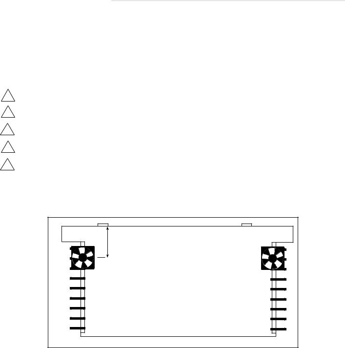
The P4000 power transformer can generate a substantial magnetic field, so caution should be exercised in the placement of low level components such as a tape deck, mixer or mic preamp to avoid inducing noise in the low level circuitry. The amplifiers can also produce considerable heat in normal operation so the primary consideration when determining a location for the amplifiers is to allow for adequate ventilation. The large heatsinks provide unrestricted airflow, but care must be taken to keep the slots in the bottom panel and top cover clear. If the amplifier is mounted in an equipment rack, make sure adjacent equipment does not impede cool air flow.
!Rack systems should have two fans 4" to 5" in from the front of the amplifier blowing upward.
Los sistemas empotrados en gabinetes (rack), deben tener dos (2) ventiladores soplando hacia arriba, ubicados
!de 10 a 12.5 ctms. detrás del frente del amplificador.
!Les chaines stéreo Rack devraient avoir deux ventillateurs placés à 4 ou 5 centimètres, en face de l'amplificateur. Rack Systeme sollten zwei eingebaute Ventilatoren haben, die Luft von oben auf den Verstärker leiten. Die
!Ventilatoren sollten ca. 10-20cm hinter der Front des Verstärkers angebracht werden.
!Per i sistemi ad armadio sono necessari due ventilatori direzionati in su collocati dai 10 ai 13 centimetri davanti all'amplificatore.
Inadequate ventilation can shorten component life, especially when other equipment raises the ambient air temperature, so circulating fans should be considered in tight quarters.
4" to 5" |
(from fan center) |
(Bottom View) |
Fan center approximately in line with edge of unit and starting of heatsink fins
•Fans placed 4" to 5" from front of unit
•Fans placed under the unit pointing upwards
•Recommended P4000 fan is 50cfm x 2
AC LINE
The P4000 amplifier operates from a 120 volt, 60Hz AC power line. Connection is made by a 16 gauge, IEC Type 320, grounded line cord. For safety considerations only a properly grounded (earthed) receptacle should be used. If a grounded circuit is not available, do not break off the ground pin; use the proper adapter plug for a two wire receptacle. Mounted on the rear panel is the line fuse which interrupts the power to the amplifier. If this fuse blows replace it only with the same type and rating fuse. The correct replacement fuse value is printed on the rear panel of the amplifier. If the new fuse blows, this is an indication of a fault with the amplifier. Servicing should be performed only by a qualified technician.
– 3 –
INPUT
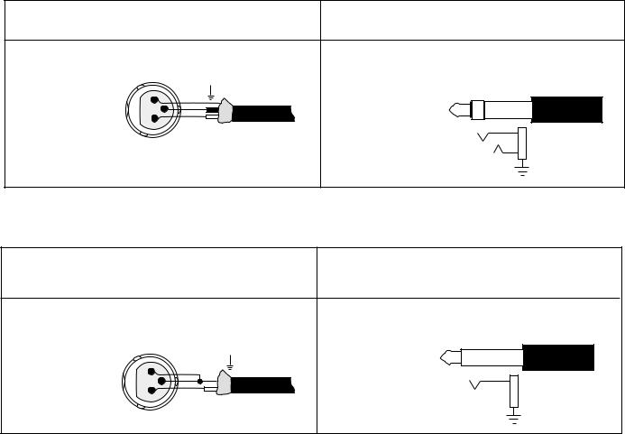
The input jacks located on the back of the amplifier are dual function connectors which accept 1/4" Phone (Tip Ring Sleeve) or XLR plugs. The 1/4" Phone jack is connected according to conventional usage. The XLR jack is connected according to the IEC and AES standard.
|
|
XLR Balanced Input |
1/4" TRS Balanced Input |
|
|
Check output of source unit for proper signal polarity |
Check output of source unit for proper signal polarity |
||||
|
|
INPUT |
FROM |
INPUT |
FROM |
|
|
|
SOURCE |
|
SOURCE |
Pin 1 |
= GND |
1 |
GND |
Tip = (+) |
|
Pin 2 |
= (+) |
|
|||
– |
|
|
|||
3 |
Ring = (–) |
|
|||
Pin 3 |
= (–) |
+ |
|
||
2 |
|
Sleeve = GND |
|
||
|
|
|
|
+ |
|
|
|
|
|
– |
|
|
|
|
|
SHIELD |
|
Many popular mixers use unbalanced outputs and can be used with the Hafler amplifier. To minimize residual ground noise, we recommend using twisted pair cable or short cable lengths in this type of configuration.
|
|
XLR Unbalanced Input |
1/4" TRS Unbalanced Input |
|
|
Connect (–) and GND (shield) terminals at both ends of cable to |
|
|
|||
|
prevent unstable amplifier operation |
|
|
||
|
|
|
|
INPUT |
FROM |
|
|
INPUT |
FROM |
|
SOURCE |
|
|
|
SOURCE |
Tip = (+) |
|
Pin 1 |
= GND |
|
SHIELD |
|
|
1 |
Sleeve = GND |
|
|||
Pin 2 |
= (+) |
|
|
||
3 |
+ |
+ |
|
||
Pin 3 |
= GND |
2 |
|
|
|
|
|
|
|
||
|
|
|
|
SHIELD |
|
OUTPUT CONNECTIONS
The speaker output connectors are dual binding posts. These binding posts will directly accept 12 AWG wire or banana plugs and are spaced on 3/4" centers to accept dual banana plugs.
MONOPHONIC USE
For systems with high power requirements, the amplifiers can be configured for single channel bridged mono operation. To bridge the amplifier, set the front panel Normal/Bridged Mono switch to the Bridged Mono position. Only the Channel 1 input and level control is used. The speaker is connected to the RED output binding posts.
– 4 –

!the amplifier output cannot be used in this application.
Cuando el amplificador esté en modo puente (bridge), la salida del mismo es flotante (sin neutro).
!Cualquier parlante que necesite una tierra común de la salida del amplificador, no puede ser usado cuando el modo puente esté activado.
!Lorsque l'amplificateur est relié, la puissance de rendement est émise. Tout haut-parleur nécessitant l'utilisation d'une même fiche que celle de l'amplificateur, ne peut pas être utilisé dans cette application.
!Wenn der Verstärker gebrückt wird, ist der Ausgang schwimmend geerdet. Alle Lautsprecher, die allgemeine Masse vom Verstärker nutzen, können in dieser Konfiguration nicht eingesetzt werden.
Nel caso di un'amplificatore ostruito, l'uscita é fluttuante non utilizzare in questa applicazione un
!altoparlante che richiede la messa a terra in comune con l'uscita dell'amplificatore.
Since a bridged amplifier shares the load between the two channels, each channel will effectively drive half
!of the load. Therefore, for bridged mono operation we recommend using an eight ohm load as the minimum impedance.
Ya que un amplificador en puente comparte la carga entre los dos canales, cada canal manejará
!efectivamente la mitad de la carga. Por lo que, para la operación en modo puente (mono) recomendamos el uso de una carga de ocho ohmios como la mínima impedancia.
Étant donné que l'amplificateur, une fois connecté, distribue la même charge entre les deux canaux,
!chaque canal conduira, de façon efficace, la moitié de la charge. C'est pourquoi, pour les opérations conduites en “mono”, nous recommandons l'utilisation d'une charge de huit ohm comme impédance minimale.
!Wird der Verstärker gebrückt, “sieht” dieser nur die halbe angelegte Last. Aus diesem Grund geben wir für die gebrückte mono Operation eine minimale Last von 8 Ohm vor.
Visto che un'amplificatore ostruito divide il carico tra i due canali, ogni singolo canale in effetti conduce
!meta del carico. Quindi, per il funzionamento monofonico ostruito dell'amplificatore si raccomanda l'utilizzo di un carico di 8 ohm impedenza minima.When the amplifier is bridged the output is floating. Any speaker which requires a common ground from
– 5 –
 Loading...