


THE
POWER AMPLI FIER
for ASSEMBLY and OPERATION
CAUTION: IF THE FUSES BLOW, |
|
|
|
SOME DISTORTED SOUND CAN BE |
|
|
|
HEARD. THEREFORE IF AMPLIFIER |
|
|
|
MALFUNCTIONS, ALWAYS CHECK |
LM153 |
|
|
|
|||
FOR BLOWN FUSES FIRST. |
Please refer to this serial |
||
$3.00 |
|||
|
number in all communications |
||
|
regarding this equipment. |
||
THE DAVID HAFLER COMPANY |
|
|
|
5910 Crescent Boulevard, Pennsauken, New Jersey 08109 |
|
||
|
|
|
|
DH-500

Power Rating: Less than 0.025% total harmonic distortion at any power level up to 255 watts continuous average power per channel into 8 ohms at any frequency between 20 Hz and 20 kHz with both channels driven.
IM Distortion (SMPTE): Less than 0.007% from 1 watt to 255 watts into 8 ohms
Typical THD at 255 watts into 8 ohms: 1 kHz-0.002%; 10 kHz-0.007%
Frequency Response into 8 ohms: -3 dB, 0.5 Hz to 120 kHz at 1 watt  dB, 5 Hz to 40 kHz at 255 watts
Typical Channel Separation at 1 kHz: 60 dB
Signal to Noise Ratio: Exceeds 100 dB referred to 255 watts into 8 ohms, unweighted Exceeds 90 dB referred to 1 watt into 8 ohms, A weighting
Input Impedance: 47,000 ohms
Input Sensitivity: 2.35 volts for 255 watts into 8 ohms; 0.145 volts for 1 watt
Damping Factor: 200 to 1 kHz into 8 ohms; 60 to 10 kHz into 8 ohms
Rise Time: 10 kHz, 80 volts p/p square wave, 10% to 90%: 2.5 us.
Slew Rate: 1 kHz, 120 volts p/p square wave: 45 V/us.
Semiconductor Complement: 27 transistors, 12 power Mosfets, 33 diodes, 8 zener diodes, one integrated circuit, one diode bridge.
Power Consumption: 240 VA quiescent; 1200 VA @ rated power into 8 ohms, 2 channels
Size: 7-l/4” high, 19” wide, 13” deep including handles
Net Weight: 45 lbs.
Shipping Weight: 49 lbs.
CAUTION: For continued protection, replace the power fuse only with the same type and rating as indicated.
WARNING: TO PREVENT FIRE OR SHOCK HAZARD, DO NOT EXPOSE THIS EQUIPMENT TO RAIN OR MOISTURE.
 Copyright 1987. All rights reserved.
INTRODUCTION
The Hafler DH-500 is a two channel audio power amplifier designed to the very highest performance standards. It is available as a kit, or factory assembled. Its power rating of 255 watts per channel is very conservative, and it can deliver appreciably higher powers into impedances below the rated 8 ohms. You must be very cautious in the application of this amplifier, as its output capability is more than most speakers can safely tolerate. We urge you to read the “Operation” section of this manual so your speakers will be reasonably protected. The best protection is still common sense in choosing program levels which your speakers can tolerate.
The DH-500 combines power MOSFET technology with a uniquely simple and effective circuit which reduces all types of distortion at all power outputs, over the entire audio spectrum, to levels where the finest test equipment has great difficulty in measuring it. The DH-500 sets a new high in reliability and resistance to abusive operating conditions at such high powers. This is one of the direct benefits of the power MOSFET’s ability to current limit under abnormal conditions.
Where the conventional bipolar transistor must be protected by special circuits from entering “thermal runaway” when it gets hot due to heavy signals, tending to get even hotter, the MOSFET self-corrects to reduce the current, and thus the heat under the same conditions. You thus gain the dual advantages of simpler circuitry and the elimination of one of the chief causes for distorted signals imposed on the music-the sound of the actuation of complex protective circuits.
The speed-measured as the slew rate-of the DH-500 delivers unmatched transient linearity, revealing the most delicate nuances of the music. In refining the basic Hafler MOSFET circuit the overall open loop gain was reduced by using more local feedback in the input stage. This required less compensation to stabilize the circuit, with the result that it was faster overall. With the built in bandwidth
limitation at the input, all other stages are free of any transient overload.
The fully complementary, symmetrical push-pull |
circuit |
is direct coupled throughout (except at the input). |
It uses |
all silicon discrete devices in a format which is directly related to the acclaimed Hafler preamplifier circuit. With its unconditional stability into virtually any load, and its enormous power capability, the result is complete freedom from listening fatigue. The longer you listen to this remarkable amplifier, the more certain you will be that you could not have made a better choice.
While modest in cost, through the elimination of frills and gadgetry, the quality is evident not only in the sound, but in the conservatively rated components. The oversized power transformer, the conservative operating levels of the MOSFETs, the computer-grade electrolytics totalling 40,000 microfarads, the enclosed relay, the use of film capacitors in signal circuits-all are evidence of the design
efforts to achieve exceptional |
reliability simultaneo’usly |
with state of the art sonics and |
specifications. So rugged is |
the DH-500 that it can deliver over 20 amperes into a short circuit!
For those with special power needs, the DH-500 can be adapted to monophonic operation, delivering in excess of 800 watts into 8 ohms, by installing the DH-502 input bridging kit.
Those who have chosen to build this amplifier from the kit will find the assembly instructions assume no technical ability other than how to make a good solder connection. Even that has been described for those who are new to the fun of kit building. Through pre-assembly and testing of the complete signal module, the performance of the kit has already been assured, for assembly involves little more than interconnection of the power supply and control elements. You can look forward to just a few hours of construction fun, to hear the finest audio amplifier yet produced.
CONTENTS
installation .......................... |
Page 4 |
Operation ............................... |
.4 |
Connections ............................ |
.5 |
Assembly Instructions .................... |
.6 |
If Problems Arise ....................... |
.I4 |
Circuit Description ...................... |
.I5 |
Schematic Diagram ..................... |
.16 |
Component Values ..................... |
.17 |
AC Line Connections for Overseas Use |
... .I8 |
Kit Parts List ............................ |
.I9 |
Service and Warranty ................... |
.20 |
Pictorial Diagram ..................... |
Insert |
3

INSTALLATION
The DH-500 may be installed out of sight in many applications, where its power can be controlled by the AC switching of a preamplifier control unit. However, any high power amplifier may draw enormous amounts of current, so you should make sure your preamplifier has the switching capacity for the amplifier’s needs, as well as any other equipment which it also switches. inadequate switch current capacity may eventually render the switch inoperative
The power switches in Hafler preamplifiers have been chosen for their high ratings, and have been tested and deemed suitable for normal home switching of the DH500. However, if the amplifier is intended for operation at sustained high power levels, or where power switching is very frequent, or where the control unit must switch substantial additional current for other equipment, or if your control unit does not have the 15 ampere switching capacity, you should use the power switch on the DH-500, and connect it directly to the AC line. In such use, turn the amplifier on last, and switch it offfirst. This will avoid possible loudspeaker damage from turn-on transients generated by source equipment.
A power transformer of this size puts out a noticeable hum field, even though the special design of this transformer minimizes such radiation. If the amplifier is to be installed close to a record player, you should first check for freedom from hum pickup by the phono cartridge. Some cartridges are much more sensitive than others, and require more separation from the amplifier. Check at a relatively high volume setting, while swinging the tone arm throughout its arc. A few inches additional space will usually solve any problem.
Ventilation is most important! Unobstructed air circulation at the sides and back is important for long trouble-free life. A 3 speed fan operates at its lowest speed whenever the amplifier is turned on, and is automatically switched to higher speeds at the power output demands it. Air is drawn in at the sides, and expelled to the rear. With normal home music levels the cooling capacity is sufficient that the fan will rarely operate at other than low speed, where it is so quiet that your ear must be close to a vent to hear it.
The front panel is designed to facilitate mounting in a standard 19” rack. Be sure a l l of the cover screws are installed w h e n the unit is supported by the front p a n e l
OPERATION
The AC power cord should be plugged into a source of 120 volts, 60 Hz, unless the amplifier is specially provided with the multi-voltage optional transformer. Press the power switch to the right to turn the amplifier on. A red pilot lamp in the power switch signifies that it is on. If it is not illuminated, the most likely cause is a blown AC line fuse. That is the single fuse close to the switch inside the chassis. However, since the amplifier uses a 15 ampere slo-blo fuse, and the typical home circuit is also rated at 15 amps, check that as well.
To avoid the turn-on |
transients generated |
in |
many |
con- |
trol units, there is a 3 |
second delay before |
the |
relay |
con- |
nects the speakers. A few preamps may require a longer delay to avoid their internally generated turn-on pulses. Information on extending this turn-on delay is available from the company on request.
A standard 2-wire power cord was chosen in preference to a 3-wire grounded AC cord, because there is no significant current leakage in this design. Where local requirements dictate the need for a 3-wire power connection, a
ground |
lug may be attached to the chassis adjacent to the |
AC line |
fuse holder. |
If the pilot lamp should ever blink (about 2-3 times a second), this signifies that a protective thermal breaker has shut down the amplifier because ofexcessive heat sink temperature. The fan will be operating at its highest speed, and as soon as the heat sink temperature has declined, the amplifier will automatically return to normal operation.
Such an occurrence is extremely unlikely, and if the amplifier shuts down again and the lamp flashes, you should check for inadequate ventilation, or an excessive input signal, an extremely low load impedance, or an input which may have dangerous signal content (such as osciIlation). Failing evidence of this, the fan or the amplifier may have malfunctioned, Because of the very effective fan cooling, any normal signal will not cause the amplifier to overheat.
At normal home use levels, the average power con-
sumption |
is |
likely around 250 watts. The unit’s efficiency |
|
is about 5O%, so some full power tests may exceed |
the ca- |
||
pacity of |
a |
15 amp circuit. When performing tests, |
voltage |
losses due to long lines should be |
taken into |
consideration, |
or compensated for. |
|
|
Loudspeaker Fuse Selection |
|
|
The DH-500 is supplied with |
2 ampere |
fuses in the |
speaker lines. This conservative value has been chosen for initial use because most high quality speaker systems cannot safely handle very high power levels, even though a high power amplifier invariably makes them sound their best. Since a substantial overload must continue for a few seconds before a fuse blows, a 2 ampere fuse will allow very high power peaks to pass without hindrance, yet will protect most speaker systems. Smaller fuses tend to blow too easily, and it is unlikely you will be using speakers with low power ratings with the DH-500. Larger fuse sizes may
not |
adequately protect the majority of speakers intended |
for |
home listening. |

If the manufacturer of your speakers recommends a
specific fuse value for their protection, you should |
obtain |
3AG type fuses of that value and substitute them |
for the |
ones supplied. The speaker fuses are included in the amplifier design solely for speaker protection. They do not protect, or affect, the amplifier’s operation. A blown speaker fuse does not indicate malfunction-simply a
higher |
than |
normal output signal. If the amplifier produces |
a low |
level |
distorted signal, a blown speaker fuse is the |
most |
likely |
cause. |
We do not recommend the use of a slo-blo type fuse for speaker protection. If your speakers can handle the higher power levels safely, and you wish to install fuses of higher
ratings, we suggest |
for |
the |
sake of |
the |
speakers-that |
|
you increase fuse |
size |
in |
l/2 |
ampere |
increments. THIS |
|
A M P L I F I E R I S |
A B L E T O D E L I V E R |
S U B S T A N - |
||||
TIALLY MORE POWER THAN MOST SPEAKERS CAN SAFELY TOLERATE. Therefore the Hafler Com-
p a n y cannot assume any responsibility |
for |
damage to the |
load (loudspeaker) because the choice |
o f |
f u s e six is in |
your hands . |
|
|
The 2 amp fuse, with an 8 ohm load, permits continuous power up to 32 watts, with peaks well above that. 2-l/2 amps passes 50 watts; 3 amps, 72 watts; 5 amps, 200 watts. We have included a pair of 5 amp fuses as alternates, for temporary use as spares; for testing the amplifier at very high power levels; and for operation into very low load impedances, 5 amps will pass 80 watts into a 4 ohm load. We suggest that you obtain additional type 3AG fuses of the
appropriate size for your speakers.
Loudspeaker Power Ratings
There are no U.S. standards for rating the power handling capabilities of loudspeakers. As a result the manufacturers’ usual “music power” r a t i n g s , o r s u g g e s t e d amplifier limits, are of only minimal help in determining safe operating levels with amplifiers which can deliver enormous amounts of power. On the other hand, some speakers, particularly tweeters, can also be damaged through the use of too small an amplifier if it is driven into sustained clipping. However, tweeters are also more vulnerable to high level signals which are not always noticeably loud to the ear (as from electronic music sources), so
you may wish to separately protect |
the tweeters with |
fuses |
of lower rating. You must take into |
consideration the |
type |
of music, and the levels you like, to provide long term trouble-free operation of your speaker choice, when you
have |
a very powerful amplifier like the DH-500. |
If |
more than one pair of speakers will be connected to |
the amplifier, proper protection would dictate that each speaker be separately fused, since when they are operated in parallel, the combination of lower impedance and the higher power handling capacity would suggest a much larger fuse at the amplifier than would provide individual protection.
If full power tests are to be performed, particularly at low load impedances, fuse ratings above 10 amps may be required for the duration of the test.
CONNECTIONS
AC
The standard unit is intended for 120 volt, 60 Hz operation. If it is controlled by an AC switch on a preamplifier, the DH-500 power switch may be left on.
If your line voltage is other than that provided in the United States, be sure you have the alternate multi-voltage power transformer, and be sure it is wired for your mains voltage before you plug in the amplifier. The connections for other line voltages will be found in the back of this manual.
Input
Standard phono jacks are installed to accept conventional shielded cables, such as those supplied with your preamplifier. Be sure that the outer shield connection is secure, to avoid hum. The length of these cables (so as to
permit remote location |
of the amplifier, if desired) is |
lim- |
ited only by the output |
impedance of the preamplifier. |
If it |
is 1000 ohms or less, as with Hafler preamplifiers, cable lengths of up to 100 feet are permissible without loss of performance. Special low capacitance cables enable even greater distance between preamp and power amplifier. It is desirable to keep the left and right input cables close together throughout their length to minimize the likelihood of hum pickup. They should cross AC cords at right angles never running parallel to AC lines at close range.
For professional |
applications the |
phono |
inputjacks |
may |
be easily replaced |
with l/4” phone |
jacks. |
Be sure, in |
that |
case, that they are grounded to the adjacent ground lug.
Output
The loudspeakers connect to the red and black 4-way binding posts. These are of a particularly heavy duty construction to handle the high currents which may be involved. They are spaced for double banana plugs, or you can connect stranded wire through the vertical hole in the shaft which is visible when the cap is unscrewed. To be cer-
tain that |
no |
strands of wire are unsecured, a tinned end, or |
a spade |
lug |
soldered to the wire is recommended. |
Be sure to maintain correct speaker phasing by watching the lead identification in the hookup wire, and the identification of the speaker terminals. It is important that the “sense” of one speaker’s connections match the others. If the speakers are out of phase, you will find that the sonic image has a “hole in the middle”, and there will be a loss of bass. This will be most evident on monophonic material. Correct it by reversing the leads to one speaker.
Select speaker wire of sufficient size to preserve the high damping factor of the DH-500, Standard 18 gauge lamp cord is the minimum suggested, and is suitable for short distances. The next larger wire is #16. There are also a
5
number of specialty speaker cables preferred by perfectionists. If you have 4 ohm speakers, larger wire is recommended than for the typical 8 ohm speakers, too.
The black output terminals are connected to ground internally. The black terminals may be connected together (common ground) when in the normal stereo mode, to utilize headphone junction boxes, or other accessories employing a common ground system.
It is important that the red terminals never be connected
together when operating in stereo. Thus it is important that you carefully observe the proper connections when using a common ground device, to be sure there is no reversal.
In the special case where the amplifier has been internally modified to convert it to monophonic bridged opera-
tion, |
with the addition |
of the DH-502 , then |
only |
one input |
jack |
is connected, and |
the output is taken |
only |
from the |
two red terminals. Such a “floating” connection must be maintained, with no connection to the black terminals.
ASSEMBLY
There are three basic rules for success in electronic kit building:
1. Read the instructions carefully, and follow them in order.
2.Make secure solder connections which are bright and smooth.
3.Check your work carefully after each step.
The DH-500 amplifier is a versatile component with sophisticated circuitry which has been made remarkably easy to build by individuals with many years ofexperience in the design and engineering of the finest performing audio kits, and in the preparation of their manuals.
Kit building should be fun, and we are certain you will find this to be so. Assembly will be faster, easier, and more enjoyable if you have someone help you by reading the steps aloud, selecting the required parts, and preparing the necessary wire lengths in advance as you proceed. Fatigue increases the risk of error, so take a break rather than push to early completion. There are relatively few separate components in this design, to make it easy to pack everything away, if need be.
Your work area should have good lighting, the proper tools, and a place where the large pictorial diagram can be tacked to the wall within easy reach for checking. The tools should include:
1.A 40 to 60 watt pencil soldering iron with a 306” or smaller tip which reaches 700°F.
2. 60/40 (60% tin) ROSIN CORE solder , l/16” diameter or smaller.
3. A damp sponge or cloth to wipe the hot tip of the iron.
INSTRUCTIONS
4. |
A wire stripping tool for removing insulation. This can |
|
|
be a single-edge razor |
blade, but inexpensive stripping |
|
tools are safer, faster |
and easier. |
5. |
A medium-blade screwdriver (about I/4” wide). |
|
6. |
A #l or #2 Phillips head screwdriver. |
|
7. |
Needle-nose pliers (a long, narrow tip). |
|
8. |
Diagonal or side-cutting small pliers. |
|
9. |
Large “gas” or “slip-joint” pliers. |
|
10.A 1/4" “Spin-tite” nut driver may be helpful, but is not necessary.
A soldering “gun” is not recommended. The unfamiliar user is more likely to damage the etched circuit boards with its higher heat potential and unbalanced weight. Also, because he may not wait long enough for it to reach operating temperature each time it is switched on, poor solder connections are more likely. Pencil irons are much lighter and easier to use, and there is no waiting time when solder connections follow in sequence, as in kit building. Make sure you have a holder for it, though, and always unplug it when you take a break.
Proper Soldering
There are four steps to making a good solder connection:
1. Make a good mechanical connection to hold the wire in position while heat and solder is applied.
2.Heat thejunction of the wire and lug, or eyelet, with the bright, shiny tip of the iron.
3.After heating for a couple seconds, apply solder to the
iunction. It should melt immediately and flow smoothly around both surfaces.
6

4. Allow the connection to cool undisturbed.
Remember that the connection is made by the solder, not by mechanically attaching the wire to the terminal. Usually the wire is looped through the lug and crimped in place, but some prefer to just place it through the hole and rely on the stiffness of the wire to hold it while soldering. Eyelet connections, of course, are handled this way.
Good solder connections are essential for trouble-free, noise-free operation. A good solder joint does not require much solder around the conductors. Never “butter” partially melted solder on the joint, as it is useless. A good connection looks smooth and bright because the solder flows into every crevice when the parts are hot enough. The iron must have a bright, shiny tip to transfer heat easily to the junction. That’s why the damp sponge should be used frequently to wipe the tip, and occasionally you must add a small amount of solder to the tip, too. If a connection is difficult to heat, “wet” the tip with a small blob of solder to provide a bigger contact surface to the joint. Once the
solder flows around |
the conductors, |
any movement |
must |
be avoided for a few |
seconds to allow |
a good bond. |
When |
cool, check the connection by wiggling the wire. If in doubt, or if the connection is not shiny, re-heat the joint. Excess solder may be removed from a connection by heating it and allowing the solder to flow onto the iron, which is then wiped on the sponge.
ALL SOLDER USED MUST BE ROSIN CORE
Never use acid core solder or any separate flux in electronic work. Silver solder is also not suitable. If in doubt about unmarked solder, always obtain a fresh supply of rosin core solder. We recommend 60/40 for easiest use. Do not confuse it with 40160, which is harder to melt.
The general procedure is to use a hot iron for a short time to heat a connection, then add solder with the iron still in contact. Remove the solder once it flows, and then remove the iron. A cooler iron applied for a longer time is more likely to damage components, or lift the copper circuit pattern from the boards. A break in the etched circuit can be mended by simply soldering a small piece of wire across it. DO not allow much build-up of solder on the tip of the iron, or it may fall into adjacent circuitry.
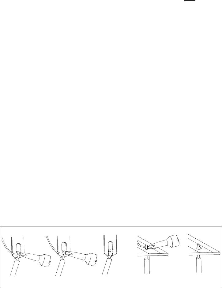
When soldering to an eyelet or hole on the board, insert the wire from the components side, and apply the iron to the bottom, leaving some bare wire exposed so that you can see that the eyelet is then filled with solder for a secure bond. A round wooden toothpick is suggested so that you can heat and clear an eyelet of solder if it hinders your inserting the wire. Some builders prefer to clear every eyelet first with a touch of the iron and toothpick. Others connect the lead by bringing it up to the center of the eyelet on top of the board, applying the iron from the bottom of the board, and pushing the lead in as the solder in the eyelet melts. If the wire has first been “tinned,” usually no additional solder is necessary, but it is a good practice to push the wire through, and then back it up a bit, to be sure solder fills the eyelet. On the bottom of the board, make certain a bright, shiny flow is evident from the wire onto the circuit pattern on the board.
"Tin ning” refers to |
the process |
of applying a light coat- |
ing of solde r to the |
bared wire |
end. This k eeps all the |
strands secured, and also makes a good connection easier. Simply touch the wire with the iron for a couple seconds, and apply solder. Allow the excess to flow away onto the iron. When properly done, the wire is uniformly bright, and no larger than before. The hookup wire supplied with this kit does not normally need tinning, for it is pre-tinned.
Wiring the Kit
If any components are unfamiliar to you, checking the pictorial diagram should quickly identify them. Or, the quantities, and the process of elimination as you check the parts list, will help. The pictorial diagram is necessarily distorted to some extent for clarity, so that you can trace every wire in a single overall view for verification as you work. You may wish to check off on the diagram as you solder each location.
To “prepare” a wire means to cut the designated length from the coil of that color, and strip about l/4” of insulation from each end. The wire supplied in the kit is #18 and #22, so you can set adjustable wire-strippers accordingly. The transformer leads are #18, and the line cord is #16. Be careful that you do not nick the wire when you strip it (that can happen more easily if you do not use wire strippers) for that weakens it. The wire supplied in this kit is “bonded stranded,” which provides exceptional flexibility with resistance to breakage for easier use.
Whenever a connection is to be soldered, the instructions will so state, or indicate by the symbol (S). If more than one wire is to be soldered to the same point, they will
be indicated by (S-2), (S-4), etc. If |
soldering |
is |
not |
called |
for, other connections have yet to |
be made |
to |
that |
termi- |
nal. They would be more difficult if the connection was already soldered. Every connection in the kit will be soldered when it is complete. After soldering a connection, it is best to clip off any excess lead length to minimize the possibility of a short circuit (as on switch lugs, where terminals are very close together), and for neatness.
Be sure that uninsulated wires cannot touch adjacent terminals or the chassis metalwork.
The symbol (#) indicates a connection is to be made to that point. When a lug number is specified without (#), it is simply a locating reference.
When the instructions call for twisting two or three wires together, the length of wire indicated anticipates a fairly tight, uniform twist by hand, of three full turns every two inches. If you find the wires too short, loosening the twist will gain some needed length.
Handle the circuit boards carefully. They represent a major part of the kit cost. Stand-up components, such as transistors, should be checked when you install the mod- ule, to be sure all leads are separated, and that the large electrolytic capacitors have not broken loose from the board.
Take the time to be accurate and neat, and you can be sure that your completed amplifier will meet the performance of a factory assembled unit, and can continue to perform properly for years to come. Check your work, and make sure the entire step has been completed before plac-
ing |
a check mark in the space provided, and continuing on |
to |
the next step. |
 Loading...