


THE
POWER AMPLIFIER
INSTRUCTIONS for OPERATION and KIT ASSEMBLY
CAUTION: |
|
|
IF THE SPEAKER FUSES BLOW, |
|
|
SOME DISTORTED SOUND CAN BE |
|
|
HEARD. THEREFORE IF AMPLIFIER |
|
|
MALFUNCTIONS, ALWAYS CHECK |
serial number in all communications |
|
FOR BLOWN FUSES FIRST. |
||
|
||
THE DAVID HAFLER COMPANY |
|
|
5910 Crescent Boulevard, Pennsauken, New Jersey 08109 |
|
Hafler DH-200 Power Amplifier

INTRODUCTION
The Hafler DH-220 is a two channel audio power amplifier designed to the very highest performance standards. It is available either as a kit, or fully assembled. Its 115 watt per channel power rating is sufficient for driving all loudspeakers in home applications, and its design assures extremely low distortion of all types. A combination of high performance, dependability, reliability, and moderate price is in the Hafler tradition of using the very latest technology to provide outstanding value.
The DH-220 circuit is a refinement of the DH-200 design, a Hafler landmark which has achieved worldwide recognition, and has elicited glowing reviews since its 1979 introduction. As in the DH-110 preamplifier, particular attention has been paid to component quality, using polypropylene or film capacitors wherever feasible, for example, for superior sound.
Combining the latest power MOSFET technology with uniquely simple and effective circuit topology reduces distortion of all types, and at all power levels, over the full audio frequency spectrum, to the vanishing point. In addition to its pace-setting performance achievements, the conservative mode of operation accomplishes a new high in long term reliability and exceptional resistance to abusive operating conditions. This is one of the direct benefits of MOSFET utilization in overcoming a serious limitation of conventional transistors - their tendency to self-destruct under other than normal operating conditions. So rugged is the DH-220 that it can deliver more than ten amperes into a short circuit!
The speed - measured as the slew rate - of this design delivers unmatched transient linearity, revealing the most delicate shadings, textures and nuances of the music, surpassing the capabilities of the most revealing loudspeakers and cartridges by a wide margin. Coupled with its unconditional stability, and ability to deliver adequate power into any loudspeaker load, the result is absolute freedom from listening fatigue. The longer you listen to this phenomenal amplifier, the more certain you will be that you could not have made a better choice.
The oversized power transformer and bridge rectifier; the massive heat sinks; the conservative operating levels of the MOSFET output devices - all are evidence of the design efforts to achieve exceptional reliability simultaneously with state of the art sonics and specifications. And this circuit is convertible to a high power monophonic amplifier with comparable stability and specifications.
The fully complementary, symmetrical push-pull circuit, which is direct coupled throughout (except at the input), incorporates all silicon devices in a format which is directly related to the highly acclaimed DH-110 preamplifier. Its unique selfprotecting output stage prevents the thermal runaway which is a common threat to solid state amplifiers. The ruggedness and conservative operation of the output stage allows the DH-220 to avoid the need for special protective circuits which could compromise audio performance. Basic protective systems provide maximum security against malfunction damage to the amplifier or the speaker: the AC line fuse, B + fuses, thermal breakers, and loudspeaker fuses. Nothing hinders the essential purity of the audio signal.
Those who use these instructions to assemble the DH-220 kit will find that the left and right audio modules (printed circuit and heat sink assemblies) are preassembled and pretested. This greatly simplifies the kit assembly so that it can be done in only a few hours without special skills or know-how. Because of the modular arrangement, it is possible to operate on one channel if the other requires service, and avoids the need to return the entire amplifier in cases where only one channel is at fault.
Accessories for special applications include provision for monophonic use; a panel for standard 19” rack mounting; and an alternative power transformer for international AC line voltages.
Through advanced engineering geared to the audio perfectionist, and an efficient no-frills approach, Hafler is making high technology high fidelity affordable.
CONTENTS
Operation |
. . . . . . . . . . . . . . . . . . . . . . . . |
Page 3 |
Assembly |
Instructions .................. |
4 |
Wiring |
the Kit ...................... |
6 |
If Problems Arise. ..................... |
10 |
|
Service and Warranty .................. |
11 |
|
AC Line Connections for Overseas Use. |
... 12 |
|
Kit Parts List ......................... |
13 |
|
Schematic |
Diagram ................... |
1 4 |
Component |
Value Listing. .............. |
15 |
Pictorial Diagram. .................. |
Insert |
|
Copyright 1984, All rights reserved.
INSTALLATION
The DH-220 is most likely to be installed out of sight in most applications, since its power may be controlled by the AC switching of most audio preamplifiers, like the Hafler DH-110. If your control unit does not provide switching capacity sufficient for the amplifier’s 7 amp needs (plus other equipment it is also switching), you should use the amplifier’s own power switch. In that case, turn on the preamplifier first; then turn the amplifier on a few seconds after the preamp has been turned on, to avoid any unnecessary turn-on transients from some preamplifiers. Likewise, switch the power amplifier off first.
If the amplifier is to be installed close to a record player, you should first check its position for freedom from hum pickup by the cartridge from the field radiated by the power transformer of the DH-220. Although the design of the transformer minimizes such radiation, certain cartridges are more sensitive
than others, and require separation from the amplifier. Check at a comparatively high volume setting, and while swinging the tone arm throughout its arc. Often a few inches additional spacing will eliminate the problem.
Be sure to provide sufficient ventilation for the amplifier. Unobstructed air circulation around the finned heat sinks and above the amplifier is important for long, trouble-free life. Never put anything on top of the cover perforations. It is normal for the top and the heat sinks to become warm in use.
It is expected that the amplifier will always be resting on its feet, which should be on a hard enough surface that air flow underneath is not obstructed. If it is mounted in a rack, or through a panel, the feet may be removed so long as adequate ventilation is provided through the bottom openings.
OPERATION
The red pilot lamp which is integral with the power switch glows whenever the amplifier is turned on. A blown AC line fuse is the most likely cause if it is not illuminated when the amplifier is switched on.
The pilot lamp also provides a high temperature indication. In the unlikely event that the amplifier ceases to function, and the amp blinks on and off steadily, it indicates that one of the thermal breakers has shut down the amplifier because of excessive temperature rise in a heat sink. When the heat has dissipated in a few minutes, the amplifier should return to normal operation. If the lamp again blinks, check for insufficient ventilation, or an excessive input signal, or an input which may have dangerous signal content (such as oscillation). Failing evidence of this, the amplifier may have malfunctioned. Because of the very large heat sinks, it is highly unlikely that any normal signal will cause the amplifier to overheat.
Loudspeaker Fuse Selection
The DH-220 power amplifier is supplied with 2 amp fuses in the speaker lines. Experience has shown that since an overload must exist for a few seconds for a fuse to blow, a 2 amp fuse will protect most speaker systems, and only blow when overload occurs. Smaller fuses tend to blow too easily, and larger fuses do not adequately protect most speaker systems.
A pair of 5 amp fuses are also supplied as alternatives for the speaker fuse holders. These should be substituted if the power output of the amplifier is to be tested, and these or intermediate values may be used if the amplifier is to be operated at very high power levels into 4 ohm loads.
If the manufacturer of your speakers recommends a specific value of fuse for their protection, we suggest that you obtain A C fuses of that value and install them in the back panel.
Loudspeaker Power Ratings
There are no U.S. standards for rating the power handling of loudspeakers. As a result, the manufacturers’ usual “music power” ratings, or suggested amplifier limits, are of only minimal help in determining safe operating levels with amplifiers which can deliver substantial amounts of power. You must take into consideration the type of music, and the levels you like, to provide long term trouble-free operation of your speaker choice, when you have a sizeable amplifier like the DH-220.
Connections
AC
The AC power cord should be plugged into 120 volts, 60 Hz, on the switched outlet of a preamplifier which can provide at least 7 amps, or 840 watts. Then the amplifier power switch may be left on, and it will be controlled by the rest of the system. Or. it may be plugged into a 120 volt wall outlet, and switched on and off independently.
If your line (mains) voltage is different, be sure you have the alternate power transformer which can accommodate several line voltages, and be sure it is wired for your mains voltage as described later in this manual before you pIug in the amplifier.
Input
Conventional shielded cables, such as those supplied with your preamplifier, provide the input signal to the sockets on the back panel of the DH-220. Be sure that the outer shield connection is secure, to avoid hum. The length of these cables (so as to permit remote location of the amplifier, if desired) is limited only by the output impedance of the preamplifier. If it is 600 ohms or less, as with the DH-101 and DH-110 Hafler preamps, for instance, cable lengths up to 50 feet are premissible without loss of

performance. Special low capacitance cables enable even greater distance between preamp and amplifier. It is desirable to keep the left and right input cables close together throughout their length to minimize the likelihood of hum pickup. Also, you should avoid running them parallel to AC cords - these should be crossed at right angles.
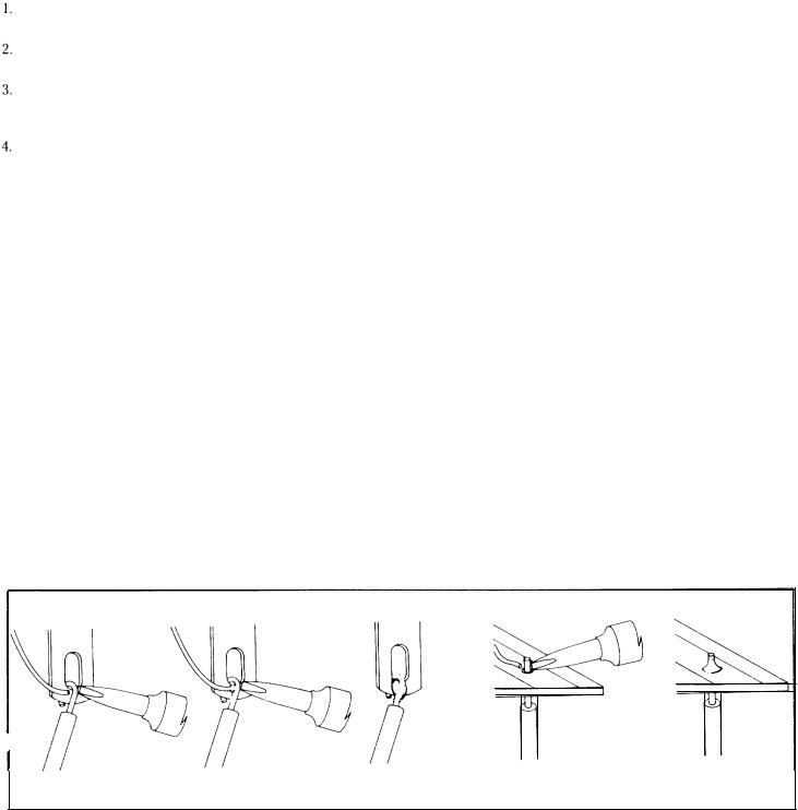
Output
The loudspeakers (or headphones) connect to the red and black terminals on the back panel. These binding posts provide several convenient alternative connecting methods. The screw cap may clamp the bared wire end, or a “spade lug” attached to it, but a better connection will be made by locating the hole drilled through the shaft of the terminal when the cap is unscrewed. Insert the twisted end of the bared wire so that the cap will clamp it in place. Always be sure that no strands of wire are unsecured, and that the bared end is not too long to risk contacting other elements. A soldered end or fitting is the safest solution.
These terminals also accept standard plug-in “banana pin connectors,” including the double ones with standard 3/4” spacing, available from electronic supply houses. These are the most convenient, especially if you may wish to interchange speakers occasionally.
It is important to maintain correct phasing of the speakers when making their connections. Some speaker terminals are coded red and black, or + and -, etc. It is important that the “sense” of one speaker’s connections match the others. If one is reversed, you will find that the sonic image has a “hole in the middle,” and that it is deficient in bass. Speaker wire always identifies one conductor to make this easy. There may be a molded ridge in one lead, or the color of the insulation on one wire is different, or the wire itself may be color coded. If pin
plugs are used, be sure they are color coded, or that you follow the indexing mark on one side of the double connectors.
Select speaker wire of sufficient size to preserve the high damping factor (and excellent speaker control) of your amplifier. Standard 18 gauge lamp cord (“zipcord”) is satisfactory for distances up to 30 feet for an 8 ohm speaker. As the distance increases, larger wire sizes are recommended. The next larger wire size is #16, and it is often preferred by perfectionists. If you have 4 ohm speakers, the maximum cable length for best results is halved.
The black output terminals are electrically connected to the chassis internally. Be certain that when the amplifier is operated in its normal stereo mode that the red output terminals are never connected together. In the special case when the amplifier has been internally modified for monophonic bridged operation, the output is taken from the two red terminals only. Then, the black terminals are left unconnected.
Headphones are normally operated from the loudspeaker outputs, but are usually connected through a junction box which provides switching from phones to speakers. Such a box usually provides some added resistance to reduce the sensitivity of the phones, and thus minimize the likelihood of hearing component noise, because of the low setting required at the volume control. Some headphone boxes utilize a “common ground” system which makes it particularly important that you carefully observe the proper connections. While the black ground terminals can be connected together, the red ones must not be.
Some headphones, such as electrostatic types, are less sensitive and may need little or no resistance in series for normal operation. These could be easily interchanged with the speakers through the use of double banana plugs.
KIT ASSEMBLY INSTRUCTIONS
There are three basic rules for success in electronic kit building:
1.Read the instructions carefully, and follow them in order.
2.Make secure solder connections which are bright and smooth.
3.Check your work carefully after each step.
The DH-220 amplifier is a versatile component with sophisticated circuitry which has been made remarkably easy to build by individuals with many years of experience in the design and engineering of the finest performing audio kits, and in the preparation of their manuals.
Kit building should be fun, and we are certain you will find this to be so. Assembly will be faster, easier, and more enjoyable if you have someone help you by reading the steps aloud, selecting the required parts, and preparing the necessary wire lengths in advance as you proceed. Fatigue increases the risk of error, so take a break rather than push to early completion. There are relatively few separate components in this design, to make it easy to pack everything away, if need be.
Your work area should have good lighting, the proper tools, and a place where the large pictorial diagram can be positioned within easy reach for checking. The tools should include:
1, A 40 to 100 watt soldering iron with a 1/4" or smaller tip which reaches at least 600°F.
2.60/40 (60% tin) ROSIN CORE solder, 1/16" diameter or smaller. (Smaller diameters are easier to work with.)
3.A damp sponge or cloth to wipe the hot top of the iron.
4.A wire stripping tool for removing insulation. This can be a single-edge razor blade, but inexpensive stripping tools are safer, faster and easier.
5.A medium-blade screwdriver (about 1/4" wide).
6.Needle-nose pliers (a long, narrow tip).
7.Diagonal or side-cutting small pliers.
8.Large “gas” or “slip-joint” pliers.
9.A 1/4" “Spin-tite” nut driver may be helpful, but is not necessary.
A soldering “gun” is not recommended. The unfamiliar user is more likely to damage the etched circuit boards with its higher heat potential and unbalanced weight. Also, because he may not wait long enough for it to reach operating temperature each time it is switched on, poor solder connections are more likely. Pencil irons are much lighter and easier to use, and there is no waiting time when solder connections follow in sequence, as in kit building. Make sure you have a holder for it, though, and always unplug it when you take a break.
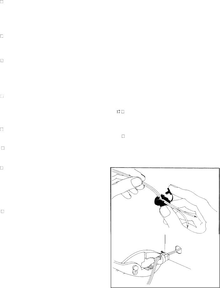
Proper Soldering
There are four steps to making a good solder connection:
Make a good mechanical connection to hold the wire in position while heat and solder is applied.
Heat thejunction of the wire and lug, or hole, with the bright, shiny top of the iron.
After heating for a couple seconds, apply solder to the junction. It should melt immediately and flow smoothly around both surfaces.
Allow the connection to cool undisturbed.
Remember that the connection is made by the solder, not by mechanically attaching the wire to the terminal. Usually the wire is looped through the lug and crimped in place, but some prefer to just place it through the hole and rely on the stiffness of the wire to hold it while soldering. Connections to numbered holes on the circuit board are handled this way.
Good solder connections are essential for trouble-free noisefree operation. A good solder joint does not require much solder around the conductors. Never “butter” partially melted solder on the joint, as it is useless. A good connection looks smooth and bright because the solder flows into every crevice when the parts are hot enough. The iron must have a bright, shiny tip to transfer heat easily to the junction. That’s why the damp sponge should be used frequently to wipe the tip, and occasionally you must add a small amount of solder to the tip, too. If a connection is difficult to heat, “wet” the tip with a small blob of solder to provide a bigger contact surface to the joint. Once the solder flows around the conductors, any movement must be avoided for a
few seconds to allow a good bond. When cool, check the connection by wiggling the wire. If in doubt, or if the connection is not shiny, re-heat the joint. Excess solder may be removed from a connection by heating it and allowing the solder to flow onto the iron, which is then wiped on the sponge.
ALL SOLDER USED MUST BE ROSIN CORE.
Never use acid core solder or any separate flux in electronic work. Silver solder is also not suitable. If in doubt about unmarked solder, always obtain a fresh supply of rosin core solder. We recommend 60/40 for easiest use. Do not confuse it with 40/60, which is harder to melt.
The general procedure is to use a hot iron for a short time to heat a connection, then add solder with the iron still in contact. Remove the solder once it flows, and then remove the iron. A cooler iron applied for a longer time is more likely to damage components, or lift the copper circuit pattern from the boards. A break in the etched circuit can be mended by simply soldering a small piece of wire across it. Do not allow much build-up of solder on the tip of the iron, or it may fall into adjacent circuitry.
When soldering to a numbered hole on the board, insert the wire from the components side, and apply the iron, leaving some bare wire exposed so that you can see that the hole is then filled with solder for a secure bond. A round wooden toothpick is suggested so that you can heat and clear the hole of solder if it hinders your inserting the wire. Some builders prefer to clear every hole first with a touch of the iron and toothpick. If the wire has first been “tinned,” no additional solder may be necessary if solder fills the hole, but it is good practice to push the wire through, and then back it up a bit, to be sure solder fills the hole from both sides. Make certain a bright, shiny flow is evident from the wire, across the hole, onto the circuit pattern on the board.
“Tinning” refers to the process of applying a light coating of solder to the bared wire end. This keeps all the strands secured, and also makes a good connection easier. Simply touch the wire with the iron for a couple of seconds, and apply solder. Allow the excess to flow away onto the iron. When properly done, the wire is uniformly bright, and no larger than before. The hookup wire supplied with this kit does not normally need tinning, for it is pre-tinned.
5
 Loading...