


THE
PREAMPLIFIER
DH-110
INSTRUCTIONS for ASSEMBLY and OPERATION
LM132
$3.00
THE DAVID HAFLER COMPANY
5910 Crescent Boulevard, Pennsauken, New Jersey 08109
Please refer to this serial number in all communications regarding this equipment.
DH-110

INTRODUCTION
Your preamplifier is the control center of your music system, acting as an interface between the sound sources-record players, tape recorders, FM and Video tuners-and the power amplifier which drives the loudspeakers. As the focal point of your system, it should be attractive and easy to use, versatile and yet functionally unobtrusive. It should contribute a minimum of noise or distortion while providing signal amplification, control of the signal level, and applicable modification of the frequency response.
The DH-110 achieves all these objectives with great versatility, providing for two record players with magnetic cartridges, two tape recorders, a tuner, and an additional stereo input for a compact (digital audio) disc player or video audio. It also includes inputs and outputs for an external signal processor such as a graphic equalizer, time delay device, or noise reduction unit. The performance of the DH-110 is exemplary, and its assembly from an array of discrete components of exceptional quality should ensure reliability and longevity of its capabilities.
Exceedingly low noise and distortion is a hallmark of the DH-110. Noise is essentially inaudible in the absence of a signal, and distortion of all types, both steady state and transient, is at or below the threshold of the finest measurement capabilities. These excellent characteristics are maintained far outside the customary 20 Hz to 20 kHz band, and signals well beyond that are handled without the need to restrict bandwidth.
Precise interchannel balance at all frequencies is maintained with close tolerance components, and RIAA phono equalization is engineered to very narrow limits, maintaining accurate phase relationships and correct spatial perspectives, as well as exceptional unit-to-unit consistency. The tone controls, which can provide contouring of response for individual needs when switched in, are normally isolated from the circuit for ruler-flat response.
The components in the DH-110 have been selected for their superb audio performance as well as for their reliability. They have been incorporated in the unique Hafler fully complementary symmetry push-pull circuit in a carefully designed circuit board layout which reduces crosstalk and maintains separation for a synergistic audio result that defies comparison, regardless of cost.
Those who have chosen to build the kit will find that its step by step instructions will ensure a properly working unit even for the novice builder. A substantial amount of preassembly has enabled us to check out each kit in nearly every aspect of performance, and makes the DH-110 a particularly fast, easy and enjoyable construction project, which you will likely complete in one evening.
We suggest that you read the installation and operation sections of this manual carefully, even though much may be familiar to you. There are some subtle and significant points which may be new, and their proper appreciation will enable maximum satisfaction with your DH-110. We wish you to have the very best in sound.
|
|
|
CONTENTS |
|
|
|
|
Installation . |
. . . . . . . . . . . . . . . . . . . . . . . . . |
Page |
4 |
Additional |
Information . . . . . . . . . . . . . . . . . . |
.16 |
|
Operation . . |
. . . . . . . . . . . . . . . . . . . . . . . . . . . . |
. |
.5 |
Functional |
Block Diagram . . . . . . . . . . . . . . . |
.16 |
|
Assembly Instructions. . . . . . . . . . . . . . . . . . . . |
.7 |
Component |
Values . . . . . . . . . . . . . . . . . . . . . |
.19 |
|||
Building the |
Kit . . . . . . . . . . . . . . . . . . . . . . . . |
. . |
.9 |
Schematic |
Diagram . . . . . . . . . . . . . . . . . . . . . |
.20 |
|
PC-14 Diagrams . . . . . . . . . . . . . . . . . . . . . . . |
. .12 |
Kit Parts |
List . . . . . . . . . . . . . . . . . . . . . . . . . . . |
.22 |
|||
If a Problem |
Arises . . . . . . . . . . . . . . . . . . . . . |
. .15 |
Service |
and Warranty . . . . . . . . . . . . . . . . . . . |
.23 |
||
Overseas AC |
Line Connections . . . . . . . . |
. . .15 |
Pictorial |
Diagram . . . . . . . . . . . . . . . . . . . . . |
Insert |
||
3

The DH-110 is provided with accessory Rack Mount end caps in addition to the standard end caps installed on the unit. These accessory caps extend the width of the front panel to that of a standard 19” rack, with appropriate mounting holes. Installation instructions are detailed later in this manual under Additional Information.
POWER CONNECTIONS
As assembled, units are normally wired for 120 VAC, 50-60 Hz, as in the USA, unless they are specially identified on the carton. In the Additional Information section you will find diagrams of alternate wiring of the power transformer to conform to other line voltages.
The power regulation of the DH-110 will provide full performance with line voltages which may vary substantially from the standard. Units wired for 120 volts, for instance, will work properly with line voltages between 95 and 130 volts.
Accessory AC outlets are provided on the back panel for other equipment. One unswitched outlet is provided for a turntable or tape recorder whose mechanical system may require disengagement through its own power switch. Most units, including power amplifiers, tuners, and many tape recorders and record players, may be connected to the switched outlets for convenient remote switching from the preamp’s front panel. The DH-110 power switch has been tested to provide adequate capacity for any Hafler power amplifier and typical related equipment. You should heed the maximum power rating printed on the back panel of the unit.
INPUTS-Magnetic Phono
There are two pairs of phono inputs, identified as Phono 1 and Phono 2. These are independent, and thus they may have different capacitive termination for differing cartridge requirements. As assembled, Phono 1 is provided with a compensation capacitor of 120 picofarads, and Phono 2 is provided with 220 picofarads. One of these values will accommodate most ‘Moving magnet’ cartridges. These have output levels intended for normal phono inputs (0.5 millivolts per centimeter or higher) and are the most popular. Some high output ‘moving coil’ design cartridges are not sensitive to capacitive loading, so they may be used with either input.
Though some phono cartridges are comparatively free of loading sensitivity, if the cartridge manufacturer specifies the proper load capacitance (which is the sum of the preamp’s internal capacitance, and the cables you use, as well as the above described capacitor), the most accurate sound will be obtained by following that recommendation. If you have chosen the DH-110 for its sonic attributes, you will be more likely than most to be aware of these differences, and will want proper cartridge termination.
The Additional Information section of this manual details the determination of the loading capacitor for a specified cartridge load. It also describes how the resistive load of the phono inputs may be changed, if needed, from the standard 47K ohms.
Moving coil design cartridges often require an auxiliary step-up transformer or pre-preamplifier (head amplifier) because of their low output signal. The DH-110 has provision for internal addition of an accessory Hafler prepreamplifer which you or your dealer can install at any time. This enables the Phono 1 input to accommodate such cartridges directly. The Additional Information describes its installation.
Adjacent to the Phono 1 input sockets are two Ground terminals on the back panel. These thumbscrews provide for connection of separate ground wires often provided on turntables, or as part of their audio cables. This ‘chassis ground’ may sometimes reduce the hum level of a system when it is connected to an earth ground, such as a cold water pipe, or the ground wire of 3-wire house wiring. However, the need for such connection varies with individual situations. After the system is operative, using a phono source, experiment with and without an earth ground to determine which provides the lowest hum, and use that.
IMPUTS-Tuner, CD/Video
These are high level (line-50 millivolts or more) signals from FM, AM or TV tuners, or compact digital audio disc, video disc, or VCR players. These inputs are grounded at the selector switch when they are not chosen for listening. The input impedance is approximately 33K ohms.
INPUTS-Tape 1, Tape 2
These are at line level and impedance. They connect to Tape Play outputs on the tape deck. They are not grounded when unused, since they can be connected by either the main selector switch or the Tape Monitor switch. They are terminated with 1 megohm resistors to avoid a possible switching transient.
RECORDING OUTPUTS
These connect to the Line Inputs of tape decks. The two pairs of outputs are wired in parallel. Thus two tape recorders receive identical signals. These outputs are buffered with a series resistor, and have an output impedance of 1.5K ohms. To provide full specification performance, the total tape recorder load should not be lower than 10K ohms (i.e. two 20k ohm recorder inputs on each channel).
Because it is possible that a preamplifier’s overall performance may be adversely affected by rectification ef-
4
fects that can result from unpowered electronic circuits in the tape decks when they are connected to the Recording Outputs, it is recommended that tape recorders be switched on when the preamplifier is in use. This is a commonly overlooked cause of less-than-ideal preamplifier performance.
Signals at these outputs are at line input level (phono signals are first amplified and equalized). These outputs are unaffected by external processing circuits, or by the DH-110’s Mono, Filter, Tone or Volume controls. Only signals indicated by the Selector switch are available, including the other tape input, so tape copying is provided using either recorder as a source.
LINE OUTPUTS
Two pairs of outputs are provided for your power amplifier connection. The set labelled ‘Via Phones’ is suggested for those who regularly listen through headphones as an alternative. These are wired so that when headphones are plugged in, the signal is disconnected from the power amplifier. Two purposes are thus served. Since many headphones require fairly high volume control settings, you avoid inadvertent high signal levels to your speakers. And a power amplifier which is turned off cannot degrade the quality of signal to the headphones-
which is otherwise a possibility. We recommend that you turn off power amplifiers before connecting headphones, or that they be plugged in before the system is switched on, as a precaution.
The Direct outputs provide conventional signal levels independent of the headphone circuit. If headphones are plugged in, the level of the Direct output will be greatly reduced. These outputs should not be used when headphone use is anticipated.
The performance specifications will be met so long as the input impedance of the power amplifier is 10K ohms or higher, and the cable capacitance is less than 1Onf. This is no problem with typical interconnecting cables up to 10 feet. If you are planning to use very long cables between preamp and power amplifier, special low capacitance cable can be obtained.
EXTERNAL PROCESSING LOOP
‘Send’ is an output at line level for the purpose of driving an external signal processor such as an equalizer, time delay, or noise reduction unit. Like the recording outputs, the load impedance should not be less than 10K ohms. The EPL ‘Return’ input impedance is 33K ohms, and should also be at line level. The EPL Return can also function as an additional high level input, switched from the front panel.
OPERATION
When you turn on the DH-110, power is also applied to the switched AC outlets on the back panel. One of the red LEDs on the front panel will light, indicating that the preamp is functioning. Typically, it will be the left-most LED, indicating that the Selector switch is determining the signal source. At turn-off, it is normal for the LED to fade slowly as the operating voltages decline.
DELAYED TURN-ON
An internal muting circuit prevents the voltage transients which may occur at turn-on or turn-off from causing annoying noises, blown fuses or damaged loudspeakers.
At turn-on, the Line Outputs (but not the Recording Outputs or EPL Send output) will be held near ground potential for a few seconds until the internal voltages have stabilized, and the unit is ready for operation. Only a faint output can be heard during this time.
At turn-off, whether by operating the preamp’s power switch, or as a result of external AC failure (a ‘brown-out’, pulled plug, or blown house fuse), the line output will be instantaneously lowered. Following power interruption, the muting circuit will initiate a few seconds delay before allowing full signal at the line outputs.
SIGNAL SELECTION
Your choice of signal sources is usually indicated by the Selector Switch, identified by the adjacent lighted LED. This switch passes line level signals direct to the Recording Outputs and to the EPL Send output as well as to the Mono switch and subsequent line amp controls. Either or both tape recorders may record this source. Tapes may be
duplicated by selecting the playback tape recorder on the Selector switch, and recording on the second machine.
PHONO AMPLIFIER
The button in the lower left of the front panel selects either Phono 1 (in the OUT position) or Phono 2. The switch may be operated to compare two cartridges while music is playing, but if them is no cartridge connected to one input, noise or RF interference may cause a small audible transient. The phono signal is accurately RIAA equalized and amplified 34dB (at 1kHz), then passed to the Selector switch at line level.
MONITOR SWITCH
To facilitate tape recording with tape decks which provide an independent monitoring facility, the DH-110 provides this second selection function. When it is OFF, the regular Selector switch determines what signals are heard. When the Monitor switch is turned to either Tape 1 or Tape 2, the line amplifier is quietly disconnected from the signal being recorded, and is connected to the tape playback instead. This enables direct comparison of the signal source with the taped replica, without affecting the recording process. Tape decks which do not provide separate record and playback heads are not able to utilize this comparison.
Note: Do not turn the Monitor switch to Tape 1 if the Selector is also set to Tape 1. Likewise avoid simultaneous Tape 2 settings on both switches. Feedback will occur, and there is a possibility of damage.
When the Monitor switch is not in the OFF position, the LED at the Monitor switch will light, in place of the Selector LED, reminding you that tape playback has been selected.
5
The following controls affect all signals which are heard through speakers or headphones. They have no effect on the signals to the recording outputs.
MONO SWITCH
When this button is IN, left and right channel information is combined, and the composite signal is fed to both left and right outputs. In this mode the sound image should appear to be centrally located between the loudspeakers. Critical listeners sometimes choose the mono mode for system evaluation, for it enables you to isolate system response from the complexity of stereo effects. This switch is also useful when listening to monophonic program material. It cancels the unwanted vertical phonograph modulations which are heard as noise from monaural records.
FILTER SWITCH
This is a low frequency cutoff to remove much of the signal below 25 Hz, such as noise, turntable rumble, or loudspeaker-turntable feedback. Even in cases where the speakers may have little response at these frequencies, this filter can be useful. Very low frequencies can modulate audible midband signals, so eliminating this interference can improve overall clarity.
Note: The Filter button should be OUT when the DH-110 is turned ON to avoid a switching transient during the first minute of operation. If it is IN at turn-on, wait one minute before releasing it.
EPL SWITCH
This is the External Processor Loop. Engaging this switch enables a signal processing device to be inserted in the preamplifier signal path. Such devices include equalizers, time delays or ambience simulators, expanders, compressors, and noise reduction systems. Since the switch permits bypassing the processor loop, an unpowered device in the EPL circuit will not deteriorate the DH-110 performance, as might be the case with switched-off tape decks in the Record Outputs. The EPL switch can also function as an additional input selection.
TONE SWITCH
Until this button is depressed, all tone control circuitry is completely removed from the signal path. Activating this button may cause a slight change in the tonal balance even when both Bass and Treble controls are in their median (detent) position. Potentiometer tolerances preclude coincident mechanical and electrical centering. The tone control circuitry limits, to an extent, the total bandpass of the DH-110.
Operation of the Tone button will be silent if it is depressed in a natural, deliberate manner. Rapid switching may generate small transient pulses.
BALANCE CONTROL
This adjusts the proportion of left and right channel signals to the Line outputs. In its detented center position the channels will be matched to ±0.1 dB. Only the Left signal
will be heard with the control fully counterclockwise, and only the Right signal at the other extreme.
The ideal situation would find symmetry in room acoustics and in the electronics, but this realization is rare. Stereo reproduction is, at best, a splendid illusion, and the function of the Balance control is to optimize this illusion in the listening space. Sound wave reflections from walls, furniture and people can unbalance the stereo ‘stage’. With judicious application of the balance control, much of the attendant distortion of stereo imaging can be overcome. With the preamplifier in the Mono mode, it will be easier to use the Balance control to centrally position the apparent sound source. This mono setting can then serve as a useful reference point, though the appropriate balance setting may vary from recording to recording in the stereo mode.
Our point is that Balance and Tone controls are intended to facilitate the most satisfying sound to the listener; it is appropriate that they be used to this end.
BASS and TREBLE CONTROLS
The Tone Switch must be IN for these controls to be effective. At full rotation, each control provides about 17 dB of boost (clockwise), or cut (counterclockwise) at the frequency extremes from the center ‘flat’ (detent) position.
The Bass control has a variable inflection, or ‘hinge’ point so that only the very low frequencies are affected by small amounts of rotation either side of center. This facilitates low frequency corrections without noticeably altering the musical balance, but speakers with diminished low frequency response will not reflect small angular movements from the detent. As the control is turned further, frequencies closer to 500 Hz are affected, so the effect is more apparent.
The Treble control has a fixed ‘hinge’ point at 1kHz and has a ‘shelving’ action above 5kHz. This affords proper correction without irritation from excessive boost at the extreme.
VOLUME CONTROL
This step action control was selected for its very accu-
rate tracking between channels, and for |
its low contact dis- |
|
tortion. Clockwise from the |
12 o’clock |
position it increases |
in increments of roughly 1 |
dB. From 12 o’clock coun- |
|
terclockwise it progresses in increasing increments to full attenuation.
HEADPHONE JACK
A 3-circuit shorting jack is connected so that the tip is the left channel, in series with one set of line outputs, so that the power amplifier is automatically disconnected when the headphones are plugged in. We recommend that you turn off the power amplifier before you connect headphones, or that they be plugged in before the preamplifier is turned on, to guard against needless transients. Be sure the volume is turned down before headphones are disconnected.
There are three basic rules for success in electronic kit building:
1:Read the instructions carefully, and follow them in order.
2.Make secure solder connections which are bright and smooth.
3.Check your work carefully after each step.
The DH-110 preamplifier is a versatile component with sophisticated circuitry which has been made remarkably easy to build by individuals with many years of experience in the design and engineering of the finest performing audio kits, and in the preparation of their manuals.
Kit building should be fun, and we am certain you will find this to be so. Fatigue increases the risk of error, so take a break rather than push to early completion. There are relatively few separate components in this design, to make it easy to pack everything away, if need be.
Your work area should have good lighting |
and the |
proper |
tools. The tools should include: |
|
|
1 . A 40 to 60 watt pencil soldering iron with |
a 3/16" or |
smal- |
ler tip which reaches 700°F |
|
|
2.60/40 (60% tin) ROSIN CORE solder, l/16” diameter or smaller.
3.A damp sponge or cloth to wipe the hot tip of the iron.
4.A wire stripping tool for removing insulation. This can
be a single-edge razor blade, but inexpensive stripping tools are safer, faster and easier.
5.A medium-blade screwdriver (about l/4” wide).
6.Needle-nose pliers (a long, narrow tip).
7.Diagonal or side-cutting small pliers.
8.Large “gas” or “slip-joint” pliers.
9.A l/4” “Spin-tite” nut driver may be helpful, but is not necessary.
A soldering “gun” is not recommended. The unfamiliar user is more likely to damage the etched circuit boards with its higher heat potential and unbalanced weight. Also,
because he may not wait long enough for it to reach operating temperature each time it is switched on, poor solder connections are more likely. Pencil irons are much lighter and easier to use, and there is no waiting time when solder connections follow in sequence, as in kit building. Make sure you have a holder for it, though, and always unplug it when you take a break.
Proper Soldering
There are four steps to make a good solder connection:
1 . Make a good mechanical connection to hold the wire in position while heat and solder is applied.
2 . Heat the junction of the wire and lug, or eyelet, with the bright, shiny tip of the iron.
3.After heating for a couple of seconds, apply solder to the junction. It should melt immediately and flow
smoothly around both surfaces.
4. Allow the connection to cool undisturbed.
Remember that the connection is made by the solder, not by mechanically attaching the wire to the terminal. Usually the wire is looped through the lug and crimped in place, but some prefer to just place it through the hole and rely on the stiffness of the wire to hold it while soldering. Eyelet connections, of course, are handled this way.
Good solder connections are essential for trouble-free, noise-free operation. A good solder joint does not require much solder around the conductors. Never “butter” partially melted solder on the joint, as it is useless. A good connection looks smooth and bright because the solder flows into every crevice when the parts am hot enough. The iron must have a bright, shiny tip to transfer heat easily to the junction. That’s why the damp sponge should be used frequently to wipe the tip, and occasionally you must add a small amount of solder to the tip, too. If a connection is difficult to heat, “wet” the tip with a small blob of solder to provide a bigger contact surface to the joint. Once the solder flows around the conductors, any movement must be avoided for a few seconds to allow a good bond. When cool, check the connection by wiggling the wire. If in doubt, or if the connection is not shiny, m-heat the joint.

Excess solder may be removed from a connection by heating it and allowing the solder to flow onto the iron, which is then wiped on the sponge.
ALL SOLDER USED MUST BE ROSIN CORE
Never use acid core solder or any separate flux in electronic work. Silver solder is also not suitable. If in doubt about unmarked solder, always obtain a fresh supply of rosin core solder. We recommend 60/40 for easiest use. Do not confuse it with 40/60, which is harder to melt.
The general procedure is to use a hot iron for a short time to heat a connection, then add solder with the iron still in contact. Remove the solderonce it flows, and then remove the iron. A cooler iron applied for a longer time is more likely to damage components, or lift the copper circuit pattern from the boards. A break in the etched circuit can be mended by simply soldering a small piece of wire across it. Do not allow much build-up of solder on the tip of the iron, or it may fall onto adjacent circuitry and cause a short circuit.
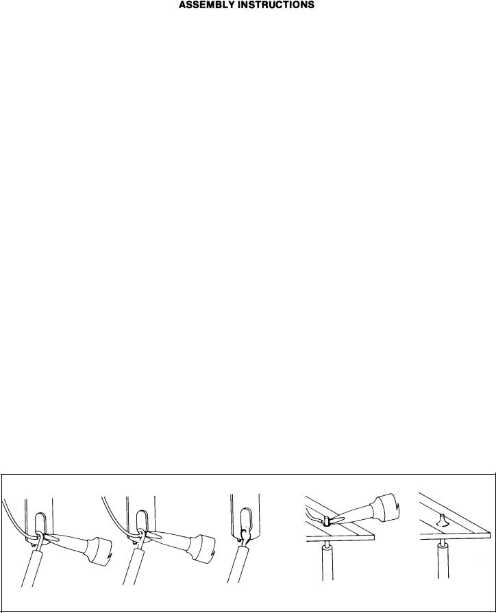
When soldering to an eyelet or hole on the board, insert the wire from the components side, and apply the iron to the bottom, leaving some bare wire exposed so that you can see that the eyelet is then filled with solder for a secure bond. A round wooden toothpick is suggested so that you can heat and clear an eyelet of solder if it hinders your inserting the wire. Some builders prefer to clear every eyelet first with a touch of the iron and toothpick. Others connect the lead by bringing it up to the center of the eyelet on top of the board, applying the iron from the bottom of the board, and pushing the lead in as the solder in the eyelet melts. If the wire has first been “tinned,” usually no additional solder is necessary, but it is a good practice to push the wire through, and then back it up a bit, to be sure solder fills the eyelet. On the bottom of the board, make certain a bright, shiny flow is evident from the wire onto the circuit pattern on the board.
“Tinning” refers to the process of applying a light coating of solder to the bared wire end. This keeps all the strands secured, and also makes a good connection easier. Simply touch the wire with the iron for a couple seconds, and apply solder. Allow the excess to flow away onto the iron. When properly done, the wire is uniformly bright, and no larger than before. The hookup wire supplied with this kit does not normally need tinning, for it is pre-tinned.
Wiring the Kit
If any components are unfamiliar to you, checking the pictorial diagram should quickly identify them. Or, the quantities, and the process of elimination as you check the parts list, will help. The pictorial diagram is necessarily distorted to some extent for clarity, so that you can trace every wire in a single overall view for verification as you work.
To “prepare” a wire means to cut the designated length from the length of that color, and strip about l/4” of insulation from each end. The wire supplied in the kit is #18 and #22, so you can set adjustable wire-strippers accordingly.
The transformer leads are #18, |
and the line cord is #16. |
Be |
||||
careful that you do not |
nick the |
wire |
when |
you |
strip it |
(that |
can happen more easily |
if you do not |
use |
wire |
strippers) for |
||
that weakens it. The wire supplied in this kit is “bonded stranded,” which provides exceptional flexibility with resistance to breakage for easier use.
Whenever a connection is to be soldered, the instructions will so state, or indicate by the symbol (S). If more than one wire is to be soldered to the same point, they will be indicated by (S-2), (S-3), etc. If soldering is not called for, other connections have yet to be made to that terminal. They would be more difficult if the connection was already soldered. Every connection in the kit will be soldered when it is complete. After soldering a connection, it is best to clip off any excess lead length to minimize the possibility of a short circuit, and for neatness.
Be sure that uninsulated wires cannot touch adjacent terminals or the chassis metalwork.
When the instructions call for twisting two or three wires together, the length of wire indicated anticipates a fairly tight, uniform twist by hand, of three full turns every two inches. If you find the wires too short, loosening the twist will gain some needed length.
Take the time to be accurate and neat, and you can be sure that your completed preamplifier will meet the performance of a factory assembled unit, and can continue to perform properly for years to come. Check your work, and make sure the entire step has been completed before placing a check mark in the space provided, and continuing on to the next step.
 Loading...